

EcoSmart Fire FLEX50.BX, FLEX78.BX2, FLEX42, FLEX68.BX2, FLEX60.BX Clearances And Installation Manual
...
CLEARANCES
AND INSTALLATION
MANUAL
Right CornerSingle Sided Left Corner Bay
PeninsulaDouble Sided
! WARNINGS:
If the InformatIon In thIs manual Is not followed exactly, a fIre or explosIon
may result causIng property damage, personal Injury or loss of lIfe.
e-NRG bioethanol is the
ONLY fuel to be used in
this appliance.
Please read these instructions completely before
installing or operating the EcoSmart™ Fire.
FLEX FIREPLACES

www.ecosmartre.com
ENGLISH
Table of
Contents
Appliance Clearances
SELECTING APPLIANCE LOCATION 1
VENTILATION 1
MINIMUM ROOM SIZE 1
Appliance Installation
FRAMING 2
BEFORE GETTING STARTED 3
SINGLE SIDED INSTALLATION
4 - 5
LEFT CORNER INSTALLATION
6 - 7
RIGHT CORNER INSTALLATION
6 - 7
BAY INSTALLATION
8 - 9
DOUBLE SIDED INSTALLATION
10 -1 1
PENINSULA INSTALLATION
12 - 13
FINISHING 14
MANTEL SURROUNDS 15
DECORATIVE BOX INFILL PLATE 16
These appliances are manufacturer approved for use only with the accompanying
UL Listed Burner/s.
OPERATION
Refer to the Operations Manual included with the Burner.

© Copyright 2004 - 2018 The Fire Company Pty Ltd. All rights reserved. V0618
Please read these instructions completely before installing and
operating the EcoSmart™ Fire.
SELECTING APPLIANCE LOCATION
The appliance is zero clearance and has the necessary clearances to
combustible frame components already built-in. They are engineered
specically to accept compatible EcoSmart Fire Burners.
When selecting a location for the appliance it is important to consider the
required minimum room sizes and clearances to walls and combustible
materials (see Clearances images below and Minimum Room Size table).
Note: Flex appliances are made from zinc sealed steel which is powder
coated with super hi-temp black paint which prevents rusting. The burners
are made of 304 stainless steel. To ensure the burner(s) continue looking
great and to avoid rust or corrosion it is important any contamination or
debris are cleaned or removed from the burner immediately.
If installed outdoors, the appliance must be located under a protective
overhang to avoid it from lling with water and being permanently
damaged. The warranty is void if the product is damaged as a result of
installation in an exposed location.
When not in use, keep the burner lid closed to safeguard the burner
from debris falling into the burner chamber and causing contamination.
WARNING: Risk of Fire or Burns! Provide adequate clearance around
air openings and for service access. Observe the clearances to
combustibles recommended in this manual and the burner manual.
Ensure that your re is positioned away from ammable materials
and other sources of ignition at all times. Due to high temperatures,
the appliance should be located out of trac and away from furniture
and draperies. Pay very close attention to positioning the re away
from items that may move as a result of wind and drafts. For example
trees/branches/curtains/paper and the like. Keep children at a safe
distance at all times and never leave them unsupervised when the
appliance is on or hot.
Min 1500mm
[59in]
600mm
[23.6in]
600mm
[23.6in]
Indoor Clearances
2000mm
[78.7in]
600mm
[23.6in]
600mm
[23.6in]
Outdoor Clearances (Need overhang or “roof extension” above the
replace to ensure rain will not enter the rebox. Check with local
building codes regarding requirements for overhangs / roof extensions.)
Appliance
Clearances
VENTILATION
EcoSmart Fires do not require any form of permanent xture or tting,
such as a ue for ventilation, a permanent connection or any kind of
xed utility for fuel supply.
Do not cover any existing ventilation systems or structures that
are built or installed within the chosen installation area.
To ensure adequate ventilation, make sure to follow the guidelines in
the table shown.
Underwriters Laboratories (UL) calculates adequate air exchange
as follows:
In a house of typical construction, that is, one that is not of unusually
tight construction due to heavy insulation and tight seals against air
inltration, an adequate supply of air for combustion and ventilation is
provided through inltration. However, if the Burner is used in a small
room where less than 5.7m3 [200ft3] of air space is provided for each
1000 BTU per hour of appliance rating (considering the maximum
Burner setting), the door(s) to adjacent room(s) should be kept open or a
window to the outside should be opened at least 25.4mm [1in] to guard
against potential build up of indoor air pollution. Do not install or operate
in a bathroom or any other small room.
MINIMUM ROOM SIZE
Ventilation table based on number of burners (per appliance).
Appliance Burner/s Minimum Room Size
BTU
FLEX18 1x AB3 1413 cubic feet
(40 cu. meters)
5,800
FLEX32
FLEX50.BX
FLEX68.BX2
1x XL500 2825 cubic feet
(80 cu. meters)
11,430
FLEX42
FLEX60.BX
FLEX78.BX2
1x XL700 3178 cubic feet
(90 cu. meters)
13,650
FLEX50
FLEX68.BX
FLEX86.BX2
1x XL900 3884 cubic feet
(110 cu. meters)
15,000
FLEX68
FLEX86.BX
FLEX104.BX2
1x XL1200 4061 cubic feet
(115 cu. meters)
16,200
FLEX86
FLEX104.BX
FLEX122.BX2
2x XL900 7768 cubic feet
(220 cu. meters)
30,000
FLEX104
FLEX122.BX
FLEX140.BX2
2x XL1200 8122 cubic feet
(230 cu. meters)
32,400
FLEX122
FLEX140.BX
FLEX158.BX2
3x XL900 11652 cubic feet
(330.2 cu. meters)
45,000
FLEX158 3x XL1200 12183 cubic feet
(345 cu. meters)
48,600
NOT INTENDED FOR USE AS A PRIMARY HEAT SOURCE.
This appliance is tested and approved as either a supplemental
room heat or as a decorative appliances. It should not be factored as
primary heat in residential heating calculations.

www.ecosmartre.com
ENGLISH
These appliances must be installed into a xed secure position
before being operated.
NOTICE: DO NOT INSTALL DIRECTLY BESIDE OR NEAR
WALLPAPER, LAMINATE, VENEER OR ANY SURFACE THAT IS NOT
DESIGNED TO WITHSTAND HEAT AND HIGH TEMPERATURES
(the heat will impact the material, and in some circumstances the
glue used for its application). THE AREA AROUND THE APPLIANCE
GETS HOT. HEAT SENSITIVE/REACTIVE MATERIALS SHOULD
NOT BE USED. DO NOT PLACE FLAMMABLE OBJECTS ON OR
AROUND THE APPARATUS.
These appliances are not designed to incorporate doors or opening
covers.
The appliance must remain open at all times for ventilation – it is not
designed to operate as an oven or similar “hot box” – the ame must
have a constant supply of air to operate and be able to circulate and
distribute the heat eectively
DO NOT PACK REQUIRED AIR SPACES (the space between
the appliance and the spacer ) WITH INSULATION OR OTHER
MATERIALS. THE AIR SPACERS ARE NEEDED TO ENSURE
PROPER TEMPERATURES ARE MAINTAINED BEHIND THE
APPLIANCE.
Do not modify the appliance in any way during installation. Cutting of
sheet metal parts of the appliance is prohibited.
Expansion and contraction of internal parts due to heating and
cooling o may create noise. This is normal.
WARNING: DO NOT OPERATE WITHOUT THE GLASS
WINDSCREEN
The appliance must be fully assembled before being operated.
Failure to install (or removal of) glass panels will void the
warranty and render the product unapproved for use with the
included burner.
FRAMING
Important Considerations for Framing
1. The appliance must be installed on a level surface capable of
supporting the appliance, burner, glass charcoal and full fuel
capacity.
2. The framing dimensions shown in the instructions are the
optimum dimensions that allow best t with gyprock / sheetrock /
plasterboard (or other facing/nishing material) after the appliance
has been installed.
3. Prepare the installation location. If placing the appliance on a
platform, build the platform, making sure to accommodate the
weight of the appliance, burner, glass charcoal and fuel. Verify that
the platform is level.
In the case of insucient capacity to hold the weight of the
appliance, measures must be taken to reinforce the setting (for
example installation of a plate for load distribution) so that the
setting is suitable for installation.
IMPORTANT: The framing above the appliance must be self-
supporting. The appliance is not load-bearing.
DEFINITIONS
Combustible materials - Materials made of or surfaced with wood,
compressed paper, plant bers, plastics, or other material that can
ignite and burn, whether ame produced or not, or plastered or un-
plastered shall be considered combustible materials.
Non-combustible materials - materials which will not ignite and
burn. Such materials are those consisting entirely of steel, iron,
brick, tile, concrete, slate, glass or plasters, or any combination
thereof. HardieBacker®, WonderBoard®, Durock® or materials
that are reported as passing ASTM E 136, Standard Test Method
for Behavior of Materials in a Vertical Tube Furnace at 750C shall be
considered non-combustible materials.
NOTE: Illustrations reect typical installations and are for DESIGN
PURPOSES ONLY. Illustrations/diagrams are not drawn to scale.
Actual installation may vary due to individual design preferences.
Appliance
Installation

© Copyright 2004 - 2018 The Fire Company Pty Ltd. All rights reserved. V0618
Appliance
Installation
BEFORE GETTING STARTED
1. Carefully remove the appliance and components from the packaging
2. Inspect and report any parts damaged in shipment, particularly the
condition of the glass windscreen.
3. Read all of the instructions before starting the installation. Follow
these instructions carefully during the installation to ensure maximum
safety and benet.
WARNING: Risk of re or explosion! Damaged parts could impair
safe operation. Do not install damaged, incomplete or substitute
components.
Appliance Crate Burner Carton
Burner
Jerry Can Spill
Proof Safety Spout
Baes
Lighter
Safety Documents Folder
Lighting Rod
Operations Manual
Jerry Can
Black Glass Charcoal
Wind Screen
Appliance
Red Stability Brackets
FLEX Manual

www.ecosmartre.com
ENGLISH
Single Sided
Installation
Equipment required: Power Drill, Screwdriver, Level, Hand Trowel for
Plaster, Silicone Gun, Caulk Gun
1. Construct the main wall framework with the opening size shown in
Table A. The base of the frame can be a solid bench/platform, which
will assist in leveling up the appliance when in position.
Table A: Framework Opening Sizes
Physical appliance dimensions should be veried against cut out dimensions BEFORE
installation begins to conrm tolerances align.
APPLIANCE
W
mm [in]Dmm [in]H mm [in]
Weight*
kg [lbs]
FLEX18SS
488 [19.2]
365
[14.4]
730 [28.7] 25.7 [56.5]
FLEX32SS
922 [36.3]
365
[14.4]
730 [28.7] 45.7 [100.5]
FLEX42SS
1177 [46.3]
365
[14.4]
730 [28.7] 60 [131.9]
FLEX50SS
1380 [54.3]
365
[14.4]
730 [28.7] 71.4 [157.1]
FLEX50SS.BX
1380 [54.3]
365
[14.4]
730 [28.7] 69.9 [153.8]
FLEX60SS.BX
1634 [64.3]
365
[14.4]
730 [28.7] 83.9 [184.6]
FLEX68SS
1840 [72.4]
365
[14.4]
730 [28.7] 97.1 [213.6]
FLEX68SS.BX
1840 [72.4]
365
[14.4]
730 [28.7] 95.1[209.2]
FLEX68SS.BX2
1840 [72.4]
365
[14.4]
730 [28.7] 93.9 [206.7]
FLEX78SS.BX2
2090 [82.3]
365
[14.4]
730 [28.7] 107.8 [237.1]
FLEX86SS
2300 [90.5]
365
[14.4]
730 [28.7] 121.5 [267.3]
FLEX86SS.BX
2300 [90.5]
365
[14.4]
730 [28.7] 119.4 [262.7]
FLEX86SS.BX2
2300 [90.5]
365
[14.4]
730 [28.7] 118.8 [261.4]
FLEX104SS
2760 [108.7]
365
[14.4]
730 [28.7] 146.2 [321.6]
FLEX104SS.BX
2760 [108.7]
365
[14.4]
730 [28.7] 145.2 [319.4]
FLEX104SS.BX2
2760 [108.7]
365
[14.4]
730 [28.7]
193.8 [426.4
]
FLEX122SS
3220 [126.7]
365
[14.4]
730 [28.7] 171.5 [377.3]
FLEX122SS.BX
3220 [126.7]
365
[14.4]
730 [28.7] 170.1 [374.2]
FLEX122SS.BX2
3220 [126.7]
365
[14.4]
730 [28.7] 168.9 [371.6]
FLEX140SS.BX
3680 [144.9]
365
[14.4]
730 [28.7] 195.2 [429.4]
FLEX140SS.BX2
3680 [144.9]
365
[14.4]
730 [28.7] 193.8 [426.4]
FLEX158SS
4140 [163]
365
[14.4]
730 [28.7] 222.1 [488.6]
FLEX158SS.BX2
4140 [163]
365
[14.4]
730 [28.7] 218.9 [481.6]
* Appliance weight includes burner/s (dry weight excluding fuel), glass charcoal and glass. It
does NOT include glass charcoal for side boxes.
IMPORTANT: The framing above the appliance must be selfsupporting. The appliance is not load-bearing.
2. Slide the appliance inside the framing cavity (the base of the
appliance can sit directly on top of the 2 x 4 framing material). The
appliance is shipped with red stability bracket(s) installed on the open
side(s) to keep the appliance square while in transport and during
installation. Keep the bracket(s) on while framing up the setting to
assist in minimizing movement of the appliance.
3. Secure the appliance to the framework with screws using the
existing mounting holes on the appliance anges. Make sure that the
appliance is level before securing it in place.
4. Remove the red stability brackets.

© Copyright 2004 - 2018 The Fire Company Pty Ltd. All rights reserved. V0618
Single Sided
Installation
5. Complete the construction by nishing the wall paneling around the
appliance. (See section on FINISHING INSTRUCTIONS and ensure that
you fully understand where non combustible materials must be used.)
6. Place the burner into position.
7. Remove the dust protective tape that covers the windscreen
mounting slots.
8. If your appliance includes a decorative box on the left / right or both,
insert the internal glass panel/s by feeding the glass upwards into the
slot then pushing down into the positioned clips.
9. Install the windscreen by inserting the two ends into the appropriate
slots in the appliance. Use a small amount of pressure to push the
windscreen in place until it bottoms out into the hidden glass clips.
WARNING: The glass used is toughened glass - which means it is
stronger than normal glass. Importantly, even though it is stronger,
toughened glass still has weaknesses. The corners and sides are
specic pressure points where it is more fragile and can break if care
is not taken. Glass breaks into many small pieces. Take care to avoid
cuts. We recommend you wear protective gloves when handling glass.
10. Spread the glass charcoal evenly around the appliance tray.
CAUTION: Make sure the burner lid is closed. Keep the glass
charcoal away from the burner ange to avoid glass charcoal from
accidentally going into the burner chamber. Be careful not to scratch
the burner.

www.ecosmartre.com
ENGLISH
Left Corner & Right Corner
Installation
Equipment required: Power Drill, Screwdriver, Level, Hand Trowel for
Plaster, Silicone Gun, Caulk Gun
1. Construct a main wall framework leaving an opening as shown in
Table B. The base of the frame can be a solid bench/platform, which
will assist in leveling up the appliance when in position.
NOTE: Illustrations are of Left Corner installation.
Table B: Framework Opening Sizes
Physical appliance dimensions should be veried against cut out dimensions BEFORE
installation begins to conrm tolerances align.
APPLIANCE
(LC & RC)
W
mm [in]Dmm [in]H mm [in]
Weight*
kg [lbs]
FLEX18LC
470 [18.5]
365
[14.4]
730 [28.7]
33 [72.6]
FLEX32LC
902 [35.5]
365
[14.4]
730 [28.7]
48.8 [107.4]
FLEX42LC
1157 [45.5]
365
[14.4]
730 [28.7]
63.3 [139.3]
FLEX50LC
1362 [53.6]
365
[14.4]
730 [28.7]
71.6k [157.5]
FLEX50LC.BX
1362 [53.6]
365
[14.4]
730 [28.7]
73.1 [160.8]
FLEX60LC.BX
1617 [63.7]
365
[14.4]
730 [28.7]
87.1 [191.6]
FLEX68LC
1822 [71.7]
365
[14.4]
730 [28.7]
100.3 [220.7]
FLEX68LC.BX
1822 [71.7]
365
[14.4]
730 [28.7]
95.3 [209.7]
FLEX68LC.BX2
1822 [71.7]
365
[14.4]
730 [28.7]
97kg [213.4]
FLEX78LC.BX2
2077 [81.8]
365
[14.4]
730 [28.7]
111 [244.2]
FLEX86LC
2282 [89.8]
365
[14.4]
730 [28.7]
121.7 [267.7]
FLEX86LC.BX
2282 [89.8]
365
[14.4]
730 [28.7]
122.6 [269.7]
FLEX86LC.BX2
2282 [89.8]
365
[14.4]
730 [28.7]
119 [261.8]
FLEX104LC
2742 [107.9]
365
[14.4]
730 [28.7]
149.5 [328.9]
FLEX104LC.BX
2742 [107.9]
365
[14.4]
730 [28.7]
145.4 [319.9]
FLEX104LC.BX2
2742 [107.9]
365
[14.4]
730 [28.7]
146.9 [323.2]
FLEX122LC
3202 [126.1]
365
[14.4]
730 [28.7]
171.7 [377.7]
FLEX122LC.BX
3202 [126.1]
365
[14.4]
730 [28.7]
173.4 [381.5]
FLEX122LC.BX2
3202 [126.1]
365
[14.4]
730 [28.7]
169.1 [372]
FLEX140LC.BX
3662 [144.2]
365
[14.4]
730 [28.7]
197.1 [433.6]
FLEX140LC.BX2
3662 [144.2]
365
[14.4]
730 [28.7]
195.4 [429.9]
FLEX158LC
4122 [162.3]
365
[14.4]
730 [28.7]
225.5 [496.1]
FLEX158LC.BX2
4122 [162.3]
365
[14.4]
730 [28.7]
219.1 [482]
* Appliance weight includes burner/s (dry weight excluding fuel), glass charcoal and glass. It
does NOT include glass charcoal for side boxes.
IMPORTANT: The framing above the appliance must be selfsupporting. The appliance is not load-bearing.
2. Slide the appliance inside the framing cavity (the base of the
appliance can sit directly on top of the 2 x 4 framing material). The
appliance is shipped with red stability bracket(s) installed on the open
side(s) to keep the appliance square while in transport and during
installation. Keep the bracket(s) on while framing up the setting to
assist in minimising movement of the appliance. Align the top corner
ange extension panel with the threaded holes on top shelf and
screw into place with the included screws
3. Secure the appliance to the framework using the existing mounting
holes on the appliance anges. Make sure that the appliance is level
before securing it in place.
4. Remove the red safety bracket(s).

© Copyright 2004 - 2018 The Fire Company Pty Ltd. All rights reserved. V0618
Left Corner & Right Corner
Installation
5. Complete the construction by nishing the wall paneling around the
appliance. (See section on FINISHING INSTRUCTIONS and ensure that
you fully understand where non combustible materials must be used.)
6. Place the burner into position.
7. Remove the dust protective tape that covers the windscreen
mounting slots.
8. If your appliance includes a decorative box on the left / right or both,
insert the internal glass panel by feeding the glass upwards into the
slot then pushing down into the positioned clips.
9. Insert the full height glass panel into one of the open end side by
inserting the glass into the opening at the top of the
appliance
, and
lowering it into the slots in the base until it bottoms out into place.
10. Install the windscreen by inserting the glass ends into the slots. Use
a small amount of pressure to push the windscreen in place until it
bottoms out into the hidden glass clips.
WARNING: The glass used is toughened glass - which means it is
stronger than normal glass. Importantly, even though it is stronger,
toughened glass still has weaknesses. The corners and sides are
specic pressure points where it is more fragile and can break if care
is not taken. Glass breaks into many small pieces. Take care to avoid
cuts. We recommend you wear protective gloves when handling glass.
11.Spread the glass charcoal evenly around the
appliance
tray.
CAUTION: Make sure the burner lid is closed. Keep the glass
charcoal away from the burner ange to avoid glass charcoal from
accidentally going into the burner chamber. Be careful not to scratch
the burner.

www.ecosmartre.com
ENGLISH
Bay
Installation
Equipment required: Power Drill, Screwdriver, Level, Hand Trowel for
Plaster, Silicone Gun, Caulk Gun
1. Construct a main wall framework leaving an opening as shown in
Table C. The base of the frame can be a solid bench/platform, which
will assist in leveling up the appliance when in position.
Table C: Framework Opening Sizes
Physical appliance dimensions should be veried against cut out dimensions BEFORE
installation begins to conrm tolerances align.
APPLIANCE
W
mm [in]Dmm [in]H mm [in]
Weight*
kg [lbs]
FLEX18BY
460 [18.1]
365
[14.4]
730 [28.7]
40.7 [89.5]
FLEX32BY
892 [35.1]
365
[14.4]
730 [28.7]
51.9 [114.2]
FLEX42BY
1147 [45.2]
365
[14.4]
730 [28.7]
66.5 [146.3]
FLEX50BY
1352 [53.2]
365
[14.4]
730 [28.7]
71.8 [158]
FLEX50BY.BX
1353 [53.3]
365
[14.4]
730 [28.7]
76.2 [167.6]
FLEX60BY.BX
1608 [63.3]
365
[14.4]
730 [28.7]
90.3 [198.7]
FLEX68BY
1813 [71.4]
365
[14.4]
730 [28.7]
103.6 [227.9]
FLEX68BY.BX
1813 [71.4]
365
[14.4]
730 [28.7]
95.5 [210.1]
FLEX68BY.BX2
1813 [71.4]
365
[14.4]
730 [28.7]
100.2 [220.4]
FLEX78BY.BX2
2068 [81.4]
365
[14.4]
730 [28.7]
114 [250.8]
FLEX86BY
2272 [89.4]
365
[14.4]
730 [28.7]
121.9 [268.2]
FLEX86BY.BX
2272 [89.4]
365
[14.4]
730 [28.7]
125.9 [277]
FLEX86BY.BX2
2272 [89.4]
365
[14.4]
730 [28.7]
119.2 [262.2]
FLEX104BY
2733 [107.6]
365
[14.4]
730 [28.7]
152.9 [336.4]
FLEX104BY.BX
2733 [107.6]
365
[14.4]
730 [28.7]
145.6 [320.3]
FLEX104BY.BX2
2733 [107.6]
365
[14.4]
730 [28.7]
150.1 [330.2]
FLEX122BY
3193 [125.7]
365
[14.4]
730 [28.7]
171.9 [378.2]
FLEX122BY.BX
3193 [125.7]
365
[14.4]
730 [28.7]
176.7 [388.7]
FLEX122BY.BX2
3193 [125.7]
365
[14.4]
730 [28.7]
169.3 [372.5]
FLEX140BY.BX
3653 [143.8]
365
[14.4]
730 [28.7]
195.6 [430.3]
FLEX140BY.BX2
3653 [143.8]
365
[14.4]
730 [28.7]
200.3 [440.7]
FLEX158BY
4113 [161.9]
365
[14.4]
730 [28.7]
228.8 [503.4]
FLEX158BY.BX2
4113 [161.9]
365
[14.4]
730 [28.7]
219.3[482.5]
* Appliance weight includes burner/s (dry weight excluding fuel), glass charcoal and glass. It
does NOT include glass charcoal for side boxes.
MPORTANT: The framing above the appliance must be selfsupporting. The appliance is not load-bearing.
2. Slide the appliance inside the framing cavity (the base of the
appliance can sit directly on top of the 2 x 4 framing material). The
appliance is shipped with red stability bracket(s) installed on the open
side(s) to keep the appliance square while in transport and during
installation. Keep the bracket(s) on while framing up the setting to
assist in minimising movement of the appliance.
3. Ensure that the left and right side edges of the
appliance
are ush to the
frame-work studs.
4. Secure the appliance to the framework with screws using the
existing mounting holes on the appliance anges. Make sure that the
appliance is level before securing it in place.
5. Remove the red stability brackets.

© Copyright 2004 - 2018 The Fire Company Pty Ltd. All rights reserved. V0618
Bay
Installation
6. Complete the construction by nishing the wall paneling around the
appliance. (See section on FINISHING INSTRUCTIONS and ensure that
you fully understand where non combustible materials must be used.)
7. Place the burner into position.
8. Remove the dust protective tape that covers the windscreen
mounting slots.
9. If your appliance includes a decorative box on the left / right or both,
insert the internal glass panel by feeding the glass upwards into the
slot then pushing down into the positioned clips.
10. Insert the full height glass panel into one of the open end side by
inserting the glass into the opening at the top of the appliance, and
lowering it into the slots in the base until it bottoms out into place.
Repeat the same for the other side of the appliance.
11. Install the windscreen by inserting the two ends into appropriate
slots in the appliance. Use a small amount of pressure to push the
windscreen in place until it bottoms out into the hidden glass clips.
WARNING: The glass used is toughened glass - which means it is
stronger than normal glass. Importantly, even though it is stronger,
toughened glass still has weaknesses. The corners and sides are
specic pressure points where it is more fragile and can break if care
is not taken. Glass breaks into many small pieces. Take care to avoid
cuts. We recommend you wear protective gloves when handling glass.
12. Spread the glass charcoal evenly around the appliance tray.
CAUTION: Make sure the burner lid is closed. Keep the glass
charcoal away from the burner ange to avoid glass charcoal from
accidentally going into the burner chamber. Be careful not to scratch
the burner.

www.ecosmartre.com
ENGLISH
Double Sided
Installation
Equipment required: Power Drill, Screwdriver, Level, Hand Trowel for
Plaster, Silicone Gun, Caulk Gun
1. Construct a main wall framework with the opening size shown in
Table D. The base of the frame can be a solid bench/platform, which
will assist in leveling up the appliance when in position.
WARNING: Double-sided appliances cannot be inserted into a
one-way cavity wall, it must be a two-way cavity where the glass
on both sides is free from obstructions. Do not apply pressure
or materials to the glass. Double sided appliances are designed
as wall divider inserts. If you do not comply with this installation
instruction the wall could overheat and catch re.
Table D: Framework Opening Sizes
Physical appliance dimensions should be veried against cut out dimensions BEFORE
installation begins to conrm tolerances align.
APPLIANCE
W
mm [in]Dmm [in]H mm [in]
Weight*
kg [lbs]
FLEX18DB
488 [19.2] 349 [13.6] 730 [28.7]
26.5 [58.3]
FLEX32DB
922 [36.3] 349 [13.6] 730 [28.7]
46.6 [102.5]
FLEX42DB
1177 [46.3] 349 [13.6] 730 [28.7]
61.4 [135.1]
FLEX50DB
1380 [54.3] 349 [13.6] 730 [28.7]
70.8 [155.8]
FLEX50DB.BX
1380 [54.3] 349 [13.6] 730 [28.7]
70 [154]
FLEX60DB.BX
1634 [64.3] 349 [13.6] 730 [28.7]
83.3 [183.3]
FLEX68DB
1840 [72.4] 349 [13.6] 730 [28.7]
95.5 [210.1]
FLEX68DB.BX
1840 [72.4] 349 [13.6] 730 [28.7]
83.7 [184.1]
FLEX68DB.BX2
1840 [72.4] 349 [13.6] 730 [28.7]
94.8 [208.6]
FLEX78DB.BX2
2090 [82.3] 349 [13.6] 730 [28.7]
106.2 [233.6]
FLEX86DB
2300 [90.5] 349 [13.6] 730 [28.7]
102.3 [225.1]
FLEX86DB.BX
2300 [90.5] 349 [13.6] 730 [28.7]
124.5 [273.9]
FLEX86DB.BX2
2300 [90.5] 349 [13.6] 730 [28.7]
108.5 [238.7]
FLEX104DB
2760 [108.7] 349 [13.6] 730 [28.7]
145.7 [320.5]
FLEX104DB.BX
2760 [108.7] 349 [13.6] 730 [28.7]
127.1 [279.6]
FLEX104DB.BX2
2760 [108.7] 349 [13.6] 730 [28.7]
142 [312]
FLEX122DB
3220 [126.7] 349 [13.6] 730 [28.7]
145.6 [320.3]
FLEX122DB.BX
3220 [126.7] 349 [13.6] 730 [28.7]
170.1 [374.2]
FLEX122DB.BX2
3220 [126.7] 349 [13.6] 730 [28.7]
151.9 [334.2]
FLEX140DB.BX
3680 [144.9] 349 [13.6] 730 [28.7]
170.4 [374.9]
FLEX140DB.BX2
3680 [144.9] 349 [13.6] 730 [28.7]
192.9 [424.4]
FLEX158DB
4140 [163] 349 [13.6] 730 [28.7]
226.8 [499]
FLEX158DB.BX2
4140 [163] 349 [13.6] 730 [28.7]
195.2 [429.4]
* Appliance weight includes burner/s (dry weight excluding fuel), glass charcoal and glass. It
does NOT include glass charcoal for side boxes.
IMPORTANT: The framing above the appliance must be selfsupporting. The appliance is not load-bearing.
2. Remove the extension ange from the rebox so that both sides are
the same height. This will help make sliding the rebox into the frame
easier. Pay attention not to lose the screws, they will be needed again
when the ange is re-installed.
3. Slide the appliance inside the framing cavity (the bottom tray can sit
directly on top of the frame). The appliance is shipped with red stability
bracket(s) installed on the open side(s) to keep the appliance square while
in transport and during installation. Keep the bracket(s) on while framing
up the setting to assist in minimising movement of the appliance.
FRONT VIEW
4. Align the ange extension panel with the threaded holes on the
appliance. Screw it into place using the included screws (bottom row
onto appliance, top row onto framing material) to secure it into position.
BACK VIEW
5. Fix the appliance to the framework with screws using the existing
mounting holes on the appliance anges. Make sure that the
appliance is level before securing it in place.

© Copyright 2004 - 2018 The Fire Company Pty Ltd. All rights reserved. V0618
Double Sided
Installation
6. Remove the red stability bracket(s).
7. Complete the construction by nishing the wall paneling around the
appliance. (See section on FINISHING INSTRUCTIONS and ensure that
you fully understand where non combustible materials must be used.)
8. Place the burner into position.
9. Remove the dust protective tape that covers the windscreen
mounting slots.
10. If your appliance includes a decorative box on the left / right or
both, insert the internal glass panel by feeding the glass upwards
into the slot then pushing down into the positioned clips.
11. Install the windscreen by inserting the two ends into appropriate
slots in the appliance. Use a small amount of pressure to push the
windscreen in place until it bottoms out into the hidden glass clips.
Repeat the same for the back side windscreen.
WARNING: The glass used is toughened glass - which means it is
stronger than normal glass. Importantly, even though it is stronger,
toughened glass still has weaknesses. The corners and sides are
specic pressure points where it is more fragile and can break if care
is not taken. Glass breaks into many small pieces. Take care to avoid
cuts. We recommend you wear protective gloves when handling glass.
12. Spread the glass charcoal evenly around the appliance tray.
CAUTION: Make sure the burner lid is closed. Keep the glass
charcoal away from the burner ange to avoid glass charcoal from
accidentally going into the burner chamber. Be careful not to scratch
the burner.

www.ecosmartre.com
ENGLISH
Peninsula
Installation
Equipment required: Power Drill, Screwdriver, Level, Hand Trowel for
Plaster, Silicone Gun, Caulk Gun
1. Construct a main wall framework with the opening size shown in
Table E. The base of the frame can be a solid bench/platform, which
will assist in leveling up the appliance when in position.
WARNING: Three-sided appliances cannot be inserted into a
one-way cavity wall, it must be a two-way cavity where the glass
on all sides are free from obstructions. Do not apply pressure or
materials to the glass. Triple sided appliances are designed as
room divider inserts. If you do not comply with this installation
instruction the wall could overheat and catch re.
Table E: Framework Opening Sizes
Physical appliance dimensions should be veried against cut out dimensions BEFORE
installation begins to conrm tolerances align.
APPLIANCE
W
mm [in]Dmm [in]H mm [in]
Weight*
kg [lbs]
FLEX18PN
470 [18.5] 349 [13.6] 730 [28.7]
34.2 [75.2]
FLEX32PN
902 [35.5] 349 [13.6] 730 [28.7]
49.8 [109.6]
FLEX42PN
1157 [45.5] 349 [13.6] 730 [28.7]
64.7 [142.3]
FLEX50PN
1362 [53.6] 349 [13.6] 730 [28.7]
59.1 [130]
FLEX50PN.BX
1362 [53.6] 349 [13.6] 730 [28.7]
73.2 [161]
FLEX60PN.BX
1617 [63.7] 349 [13.6] 730 [28.7]
87.5 [192.5]
FLEX68PN
1822 [71.7] 349 [13.6] 730 [28.7]
102.8 [226.2]
FLEX68PN.BX
1822 [71.7] 349 [13.6] 730 [28.7]
83.9 [184.6]
FLEX68PN.BX2
1822 [71.7] 349 [13.6] 730 [28.7]
96.1 [211.4]
FLEX78PN.BX2
2077 [81.8] 349 [13.6] 730 [28.7]
110.4 [242.9]
FLEX86PN
2282 [89.8] 349 [13.6] 730 [28.7]
102.5 [225.5]
FLEX86PN.BX
2282 [89.8] 349 [13.6] 730 [28.7]
124.1 [273]
FLEX86PN.BX2
2282 [89.8] 349 [13.6] 730 [28.7]
108.7 [239.1]
FLEX104PN
2742 [107.9] 349 [13.6] 730 [28.7]
153.3 [337.3]
FLEX104PN.BX
2742 [107.9] 349 [13.6] 730 [28.7]
127.3 [280.1]
FLEX104PN.BX2
2742 [107.9] 349 [13.6] 730 [28.7]
147.3 [324.1]
FLEX122PN
3202 [126.1] 349 [13.6] 730 [28.7]
145.8 [320.8]
FLEX122PN.BX
3202 [126.1] 349 [13.6] 730 [28.7]
176.2 [387.6]
FLEX122PN.BX2
3202 [126.1] 349 [13.6] 730 [28.7]
152.1 [334.6]
FLEX140PN.BX
3662 [144.2] 349 [13.6] 730 [28.7]
170.6 [375.3]
FLEX140PN.BX2
3662 [144.2] 349 [13.6] 730 [28.7]
198.7 [437.1]
FLEX158PN
4122 [162.3] 349 [13.6] 730 [28.7]
231.8 [510]
FLEX158PN.BX2
4122 [162.3] 349 [13.6] 730 [28.7]
195.4 [429.9]
* Appliance weight includes burner/s (dry weight excluding fuel), glass charcoal and glass. It
does NOT include glass charcoal for side boxes.
IMPORTANT: The framing above the appliance must be selfsupporting. The appliance is not load-bearing.
2. Remove the extension ange from the rebox so that both sides are
the same height. This will help make sliding the rebox into the frame
easier. Pay attention not to lose the screws, they will be needed again
when the ange is re-installed.
3. Slide the appliance into the framing cavity (the bottom tray can sit
directly on top of the frame). The appliance is shipped with
red stability
bracket(s)
on the open sides to keep the appliance square while in
transport and during installation. Keep these brackets on while framing
up the setting to assist in minimizing movement of the appliance.
FRONT VIEW
4. Ensure that the back and open side edge of the appliance are ush
with frame studs.
5. Align the ange extension panel with the threaded holes on the
appliance. Screw it into place using the included screws (bottom row
onto appliance, top row onto framing material) to secure it into position.
BACK VIEW

© Copyright 2004 - 2018 The Fire Company Pty Ltd. All rights reserved. V0618
Peninsula
Installation
6. Fix the appliance to the framework with screws using the existing
mounting holes on the appliance anges. Make sure that the
appliance is level before securing it in place.
7. Remove the red stability brackets.
8. Complete the construction by nishing the wall paneling around the
appliance. (See section on FINISHING INSTRUCTIONS and ensure that
you fully understand where non combustible materials must be used.)
9. Place the burner into position.
10. Remove the dust protective tape that covers the windscreen
mounting slots.
10. If your appliance includes a decorative box on the left / right or both,
insert the internal glass panel by feeding the glass upwards into the
slot then pushing down into the positioned clips.
11. Insert the full height glass panel into the open end side by inserting
the glass into the opening at the top of the appliance, and lowering it
into the slots in the base until it bottoms out into place.
12.Install the windscreen by inserting the two ends into appropriate
slots in the appliance. Use a small amount of pressure to push the
windscreen in place until it bottoms out into the hidden glass clips.
Repeat the same for the back side windscreen.
WARNING: The glass used is toughened glass - which means it is
stronger than normal glass. Importantly, even though it is stronger,
toughened glass still has weaknesses. The corners and sides are
specic pressure points where it is more fragile and can break if care
is not taken. Glass breaks into many small pieces. Take care to avoid
cuts. We recommend you wear protective gloves when handling glass.
13.Spread the glass charcoal evenly around the appliance tray.
CAUTION: Make sure the burner lid is closed. Keep the glass charcoal
away from the burner ange to avoid glass charcoal from accidentally
going into the burner chamber. Be careful not to scratch the burner.
www.ecosmartre.com
ENGLISH
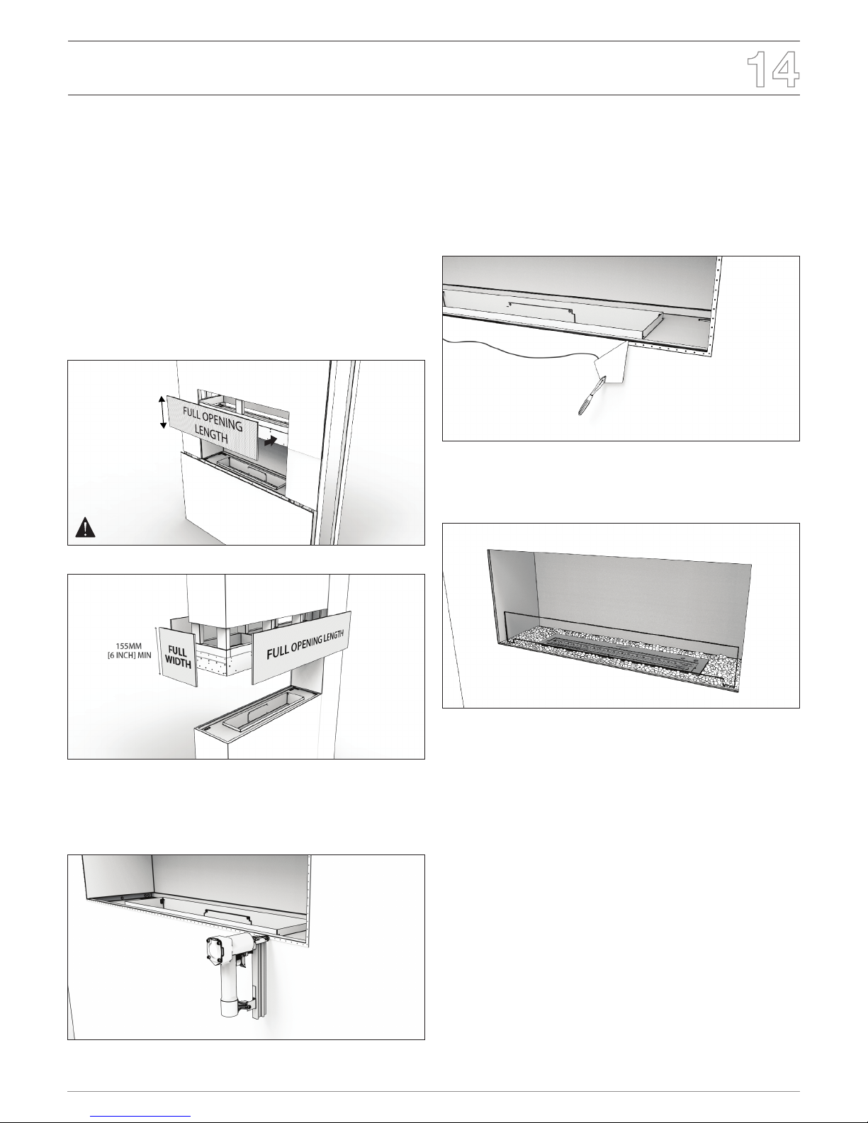
Finishing
1. Apply surrounding wall panels. Acceptable materials include bre
cement MDF, cement sheeting, stone cladding, tiles, steel, and
sheetrock.
Facing or nishing materials must never overhang into the appliance
opening.
WARNING! Risk of Fire! Do not apply combustible materials
beyond the minimum clearances. Comply with all minimum
clearances to combustibles as specied in this manual and the
burner manual.
IMPORTANT: A 155mm [6”] non combustible panel must be
installed above all sides of the appliance openings. See
examples below.
155mm [6’’] MIN
Example: Single Sided Fireplace
Example: Peninsula Fireplace
2. A metal trim bead MUST be installed on all edges (mitre the corners).
(Do not use long fasteners thicker than the wall paneling material to
avoid penetrating the appliance).
3. Plaster all seams and beads.
All joints between the nished wall sheathing and the front of the
appliance must be sealed with non-combustible materials. Sealants,
such as caulk or mastic used to seal the gap between the wall and
the appliance, should be rated at a minimum continuous exposure to
150ºC (122ºF).
4. If desired nishing includes a painted wall, 100% acrylic latex or oil-
based or standard acrylics may be used. Follow paint manufacturer’s
instructions for paint and primer application.
OPERATE ACCORDING TO THE BURNER OPERATIONS MANUAL
INCLUDED WITH THE BURNER.

© Copyright 2004 - 2018 The Fire Company Pty Ltd. All rights reserved. V0618
Mantel Surrounds
Minimum Clearances
If the setting incorporates a mantel the minimum vertical and maximum
horizontal dimensions to combustible mantel identied in the image
below must be followed.
Finishing clearances to COMBUSTIBLES
381mm [15’’] MAX
330mm [13’’] MIN
914.4mm [36’’ ]
Ceiling
50.8mm [2’’ ] MIN
Measurement is taken
from the top edge of the
Measurement is taken
from the bottom edge of the
Floor or Shelf
12.7mm [0.5’’] Sheetrock
12.7mm [0.5’’] Sheetrock
12.7mm [0.5’’]
Non-combustible board
152.4mm [6’’] Tall
Minimum vertical and maximum horizontal dimensions of
combustible mantel.
Finishing and clearances to NON-COMBUSTIBLES
101.6mm [4’’]
50.8mm [2’’]
2’’
101.6mm [4’’]
152.4mm [6’’]
Measurement is taken
from the top edge of the
Minimum vertical &
maximum horizontal
dimensions
Floor or Shelf
Minimum vertical and maximum horizontal dimensions of
non-combustible mantel.
Warning! Risk of Fire! Comply with all minimum clearances
to combustibles as specied. Framing or nishing material
closer than the minimum listed must be constructed entirely
of non-combustible materials.

www.ecosmartre.com
ENGLISH
Decorative Box
Inll Plate
For appliances with a decorative side box, an inll plate is provided to lift
the material to align with the bottom edge of the appliance. Decorative
boxes must only be used to hold non-combustible accessories/materials.
Decorative Steel Logs are available as an optional accessory. Please
contact customerservice@ecosmartre.com


Showrooms 3 & 4, 40-42 O’Riordan Street
Alexandria NSW 2015 Australia
Tel: +61 2 9997 3050 Email: info@ecosmartre.com
V0618
 Loading...