

EcoSmart PST6000, PST6550 Installation Manual

EcoWave
Installation Guide
PST6000 and PST6550

EcoWave
Installation
Guide Telkonet,
Inc.
Table of Contents
10200 W. Innovation Dr., Ste. 300
Revision 9
Milwaukee
, WI 53226
Page 1 (800) 380
-
9640
Table of Contents
Table of Contents ................................................................................................................... 1
Installation Requirements .......................................................................................................... 2
Required Equipment ............................................................................................................. 2
Hardware ........................................................................................................................ 2
Regulatory Compliance .......................................................................................................... 2
FCC Notice ...................................................................................................................... 2
Wiring the EcoInsight/EcoSource ................................................................................................. 3
Wireless Installation of the EcoAir ............................................................................................... 6
Configuration ......................................................................................................................... 7
Join the EcoInsight/EcoSource to the EcoConnect ......................................................................... 7
Required Equipment ........................................................................................................... 7
Join Process ..................................................................................................................... 7
EcoAir to EcoInsight/EcoSource Association ............................................................................... 10
Associating One EcoAir with One EcoInsight/EcoSource (Standard) ................................................ 10
Associating One EcoAir with Multiple EcoInsights/EcoSources (Multi-Bind) ....................................... 12
Troubleshooting.................................................................................................................... 14
www.telkonet.com

EcoWave
Installation
Guide Telkonet,
Inc.
Installation Requirements
10200 W. Innovation Dr., Ste. 300
Revision 9
Milwaukee
, WI 53226
Page 2 (800) 380
-
9640
Installation Requirements
Required Equipment
Hardware
• EcoAir (P/N: PST6550)
• EcoInsight/EcoSource (P/N: PST6000)
• Voltmeter
• Small Phillips screwdriver
• Wire nut or electrical tape
• Wire stripper
• Wire cutter
• Security screw wrench
• Level
• Two AA Batteries
Regulatory Compliance
This device complies with Part 15 of the FCC Rules. Operation is subject to the following two conditions: (1)
this device may not cause harmful interference, and (2) this device must accept any interference received,
including interference that may cause undesired operation.
FCC Notice
This equipment has been tested and found to comply with the limits for a class B digital device pursuant to
part 15 of the FCC Rules. These limits are designed to provide reasonable protection against harmful
interference in a residential installation. This equipment generates, uses and can radiate radio frequency
energy and if not installed and used in accordance with the instructions, may cause harmful interference to
radio communications. However, there is no guarantee that interference will not occur in a particular
installation. If the equipment does cause harmful interference to radio or television reception, which can be
determined by turning the equipment off and on, the user is encouraged to try to correct the interference by
one or more of the following measures:
• Reorient or relocate the receiving antenna.
• Increase the separation between the equipment and the receiver.
• Connect the equipment into an outlet on a circuit different from that to which the receiver is
connected.
• Consult the dealer or experienced radio/TV technician for help.
In order to maintain compliance with FCC regulations, shielded cables must be used with this equipment.
Operation with non-approved equipment is likely to result in interference to radio and TV reception. The user
is cautioned that changes and modifications made to the equipment without the approval of the manufacturer
could void the user’s authority to operate the equipment.
To satisfy RF exposure requirements, this device and its antennas must operate with a separation distance of at
least 20 cm from all persons and must not be co-located or operating in conjunction with any other antenna or
transmitter.
www.telkonet.com
EcoWave
Installation
Guide Telkonet,
Inc.
Wiring the EcoInsight/EcoSource
10200 W. Innovation Dr., Ste. 300
Revision 9
Milwaukee
, WI 53226
Page 3 (800) 380
-
9640
Mounting
Best Practice
RF Interference
If the
EcoInsight/
EcoSource will be mounted inside a metal HVAC unit
or in a room with a
It may not be possible to switch off transformer supply voltage on low
-
voltage units. Use caution
Wiring the EcoInsight/EcoSource
1. Locate the wiring in the HVAC Unit.
2. Review the table below and determine where the EcoInsight/EcoSource will be mounted.
Consideration
large amount of metallic equipment, an external antenna may be necessary.
3. Turn the power off at the circuit breaker.
4. Lockout and label all circuits in accordance with local code.
5. Disconnect the existing thermostat, if any.
6. Use the voltmeter to verify the power is off.
when installing these systems.
7. Strip the LINE wire back 0.25 inches.
8. Cap the LINE wire with a wire nut or electrical tape.
9. Cut the GROUND wire so the copper is flush with the insulation.
10. Strip all wires except for GROUND back 0.25 inches.
11. Remove the security screw from the EcoInsight/EcoSource thermostat.
12. Separate the backplate from the EcoInsight/EcoSource thermostat.
13. Level the backplate using a level across the bottom of the backplate.
14. Mark the placement for the mounting screws.
15. Mount the backplate to the wall or HVAC unit using either the wall anchors (mounting to drywall) or
the self-tapping metal screws (mounting to metal).
www.telkonet.com
EcoWave
Installation
Guide Telkonet,
Inc.
Wiring the EcoInsight/EcoSource
10200 W. Innovation Dr., Ste. 300
Revision 9
Milwaukee
, WI 53226
Page 4 (800) 380
-
9640
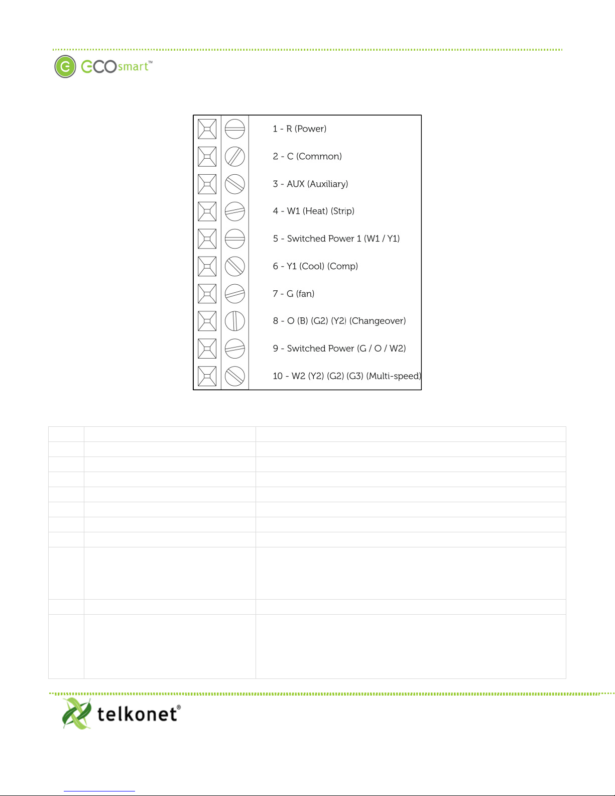
Pin Label on Backplate
Function
1 R (Power)
12-
277VAC power from HVAC, used to power the thermostat
2 C (Common)
AC Common
3 AUX (Auxiliary)
User defined
4 W1 (Heat) (Strip)
Heat call
or strip heat call (depends on programming)
5 Switched Power 1 (W1/Y1)
Provides alternate power for W1 and Y1
6 Y1 (Cool) (Comp)
Cool/Compressor call
7 G (Fan)
Fan Call
- Low speed
Multi
-
use -
depends on programming and
site requirements:
9 Switched Power 2
(G/O/W2)
Provides alternate power for G, O, and W2
Multi
-
use -
depends on programming and site requirements:
16. Refer to either the wiring diagram provided by your Telkonet Project Manager for this install or use the
wiring pinouts below in Figure 1and Table 1.
Figure 1: EcoInsight/EcoSource Wiring Pinout
Table 1: EcoInsight/EcoSource Wiring Pinout
8 O (B) (G2) (Y2) (Changeover)
10 W2 (Y2) (G2) (G3) (Multi-speed)
• Changeover
• 2nd Stage Fan
• 2nd Stage Cooling
• 2nd stage heat
• Electric heat (for HPs with strip heat, etc.)
• Emergency heat
• Other
www.telkonet.com
 Loading...