

Page 1

P/N 14000C
ES50LVP / ES90LVP
MODULATING AIR HANDLER
Installation, Operation and Maintenance Manual
Ecosmartair
105 Haist Avenue, Unit 10
Vaughan, ON L4L 5V6
905-857-9755
ecosmartair.com
Page 2

1 | P a g e
Contents
SAFETY INFORMATION .................................................................................................. 3
INTRODUCTION ............................................................................................................ 4
MODES OF OPERATION ................................................................................................. 4
Modulating Mode ................................................................................................................................. 4
Step Modulating Mode ......................................................................................................................... 5
Basic Mode ............................................................................................................................................ 5
SPECIFICATIONS ............................................................................................................ 8
QUICK START-UP PROCEDURES .................................................................................... 10
INSTALLATION ............................................................................................................ 11
Clearances ........................................................................................................................................... 11
Freeze Protection ................................................................................................................................ 11
Rear Piping Connections ..................................................................................................................... 12
Ecosmart Mounting ............................................................................................................................. 12
Plumbing ............................................................................................................................................. 12
Pump ................................................................................................................................................... 13
PIPING DIAGRAMS ...................................................................................................... 15
Tankless Water Heater Piping ............................................................................................................. 15
Combi-Boiler Piping............................................................................................................................. 16
ELECTRICAL................................................................................................................. 17
Electrical Information .......................................................................................................................... 17
Electrical Connections Made to Quick Connects ................................................................................ 17
Thermostat Wiring .............................................................................................................................. 18
Ecosmart ES50LVP/ES90LVP Wiring Diagram ..................................................................................... 19
Miscellaneous Wiring .......................................................................................................................... 20
DIP SWITCH OPTIONS .................................................................................................. 21
Switch Locations ................................................................................................................................. 21
Outdoor Temperature Select .............................................................................................................. 21
Heat CFM (ES90LVP) ........................................................................................................................... 22
Heat CFM (ES50LVP) ........................................................................................................................... 22
Page 3

2 | P a g e
System (ES990LVP and ES50LVP) ........................................................................................................ 22
Cool CFM (ES90LVP) ............................................................................................................................ 23
Cool CFM (ES50LVP) ............................................................................................................................ 23
SEQUENCE OF OPERATION ........................................................................................... 24
Full Modulation ................................................................................................................................... 24
Step Modulation ................................................................................................................................. 24
Basic Modulation Mode ...................................................................................................................... 25
Cooling Mode (Modulation, Step and Basic) ...................................................................................... 25
Dehumidification ................................................................................................................................. 26
............................................................................................................................................................ 26
Fan Mode ............................................................................................................................................ 26
Constant Low Fan Circulation ............................................................................................................. 26
Freeze Protection ................................................................................................................................ 26
Pump Exerciser .................................................................................................................................... 27
SERVICE AND MAINTENANCE ....................................................................................... 27
Filter .................................................................................................................................................... 27
Coils ..................................................................................................................................................... 27
Fan and Motor .................................................................................................................................... 27
Control and Blower Assembly Removal .............................................................................................. 27
TROUBLESHOOTING .................................................................................................... 28
Thermostat call error .......................................................................................................................... 28
External pump does not run ............................................................................................................... 28
External pump is noisy at start-up ...................................................................................................... 28
Water heater temperature and pressure relief valve is weeping ...................................................... 28
Insufficient or no heat ......................................................................................................................... 29
Cold water at hot faucet ..................................................................................................................... 29
Fan runs for cooling but not for heating ............................................................................................. 29
Heating during standby mode ............................................................................................................ 29
WARRANTY ................................................................................................................ 29
All technical information subject to change without notice.
Page 4
3 | P a g e
SAFETY INFORMATION
It is the responsibility of the installer to ensure the installation complies with all national and
local building codes and standards, in addition to the instructions outlined in this manual. All
applicable codes take precedence over any instructions made in this document.
This symbol indicates safety alerts. When you see this symbol on labels or in this
manual, be alert to the potential for personal injury. Understand and pay
particular attention to the signal words DANGER, WARNING, or CAUTION.
DANGER indicates an imminently hazardous situation, which if not avoided, will result
in death or serious injury.
WARNING indicates a potentially hazardous situation, which if not avoided, could
result in death or serious injury.
CAUTION indicates a potentially hazardous situation, which if not avoided, may result
in minor or moderate injury. It is also used to alert against unsafe practices and
hazards involving only property damage.
WARNING - Improper installation may create a condition where the operation of
the product could cause personal injury or property damage. Only a qualified
contractor, installer or service agency should install this product. Improper
installation, adjustment, alteration, service or maintenance can cause injury or
property damage. Refer to this manual for assistance.
CAUTION - This product must be installed in strict compliance with the installation
instructions and any applicable local, state, and national codes including, but not
limited to; building, electrical, and mechanical codes.
WARNING - FIRE OR ELECTRICAL HAZARD. Failure to follow the safety warnings
exactly could result in serious injury, death, or property damage. A fire or electrical
hazard may result causing property damage, personal injury or loss of life.
WARNING - Hot water from a boiler used to satisfy heating requirements can be
heated to temperatures of 180°F. Parts containing water this hot can scald very
quickly. Use extreme caution when servicing or performing maintenance on any
parts containing hot water. To avoid severe burns, allow equipment to cool before
performing maintenance.
Page 5
4 | P a g e
INTRODUCTION
The ecosmart hydronic furnace is designed to maximize performance and comfort in residential
or light commercial applications. The ecosmart can be used with a variety of heat sources such
as boilers and water heaters and can be implemented in combo systems that provide domestic
hot water as well as space heating.
Smart control systems within the ecosmart allow extraction of maximum heat by allowing
condensing high efficiency heat sources to work at their maximum efficiency while providing
ultimate comfort with unmatched performance.
Simple, independent heat/cool and system parameters can easily be set by the installer to
adjust for a wide variety of installations. Various parameters are automatically monitored and
fan and pump speeds vary simultaneously. The ecosmart has a built-in variable speed pump
controller that can vary the speed of a standard single speed AC pump.
MODES OF OPERATION
Three modes of operation are available:
1. Full modulation – full control of fan and pump (requires outdoor temperature sensor).
2. Step modulation – timed fan and pump sequencing.
3. Single stage – standard furnace emulation.
Modulating Mode
(ecosmart outdoor sensor installed)
Water temperature is set at the heat generator by referring to the heat generator performance
data. It is best to maintain constant water temperature at the heat generator.
If the heat generator comes with an optional outdoor temperature sensor do not
install it as it will conflict with the ecosmart control.
Page 6

5 | P a g e
The fan operates at the speed selected on the HEAT CFM switch during the setup. Fan and
pump speed automatically reduce as outdoor temperature rises. Fan CFM may reduce by up to
30% from the HEAT CFM switch setting depending on outdoor temperature.
If the heat generator includes a built-in pump, and it is directly connected to the ecosmart, the
ecosmart will vary the pump automatically. If the system is configured for primary/secondary
pumping and the heat generator includes a pump, the secondary pump can be controlled by
the ecosmart.
Step Modulating Mode
(ecosmart outdoor sensor not installed)
Water temperature is set at the heat generator by referring to the heat generator performance data.
Fan operates at 50% of the HEAT CFM setting for 5 minutes then increases to 75% for a further 5
minutes, then increases to 100% until the thermostat is satisfied. If the pump is controlled by the
ecosmart, its speed will be adjusted accordingly as the ecosmart goes through its stages. If the pump is
controlled by the heat source, it will function according to the heat source control strategy.
Basic Mode
(ecosmart outdoor sensor not installed)
Water temperature is set at the heat generator by referring to the heat generator performance
data. Fan operates at 100% of selected HEAT CFM and pump operates at maximum speed until
the thermostat is satisfied.
Page 7
6 | P a g e
PERFORMANCE RATINGS
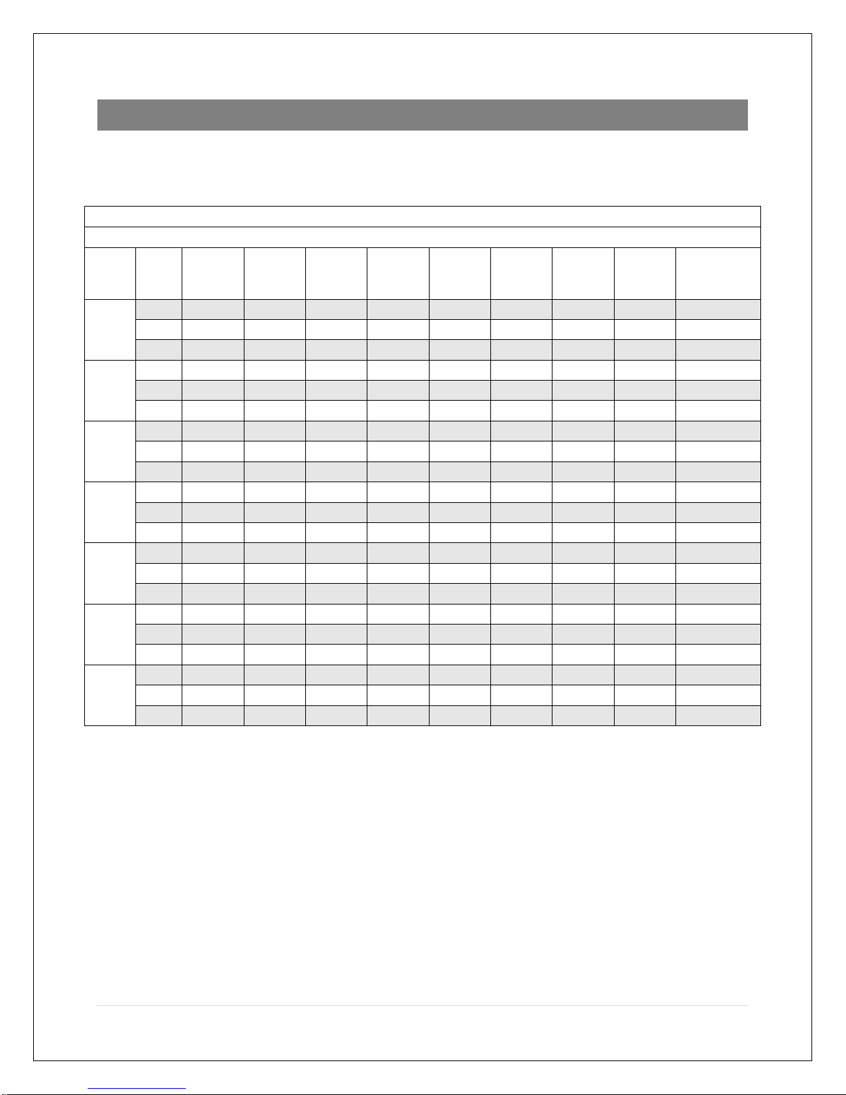
ES50LVP
Performance Data - Hot Water Capacities (BTUH) @ 70°F Entering Air Temperature
Entering Water Temperature
CFM
GPM
110°F
120°F
130°F
140°F
150°F
160°F
170°F
180°F
Water PD
feet WC
@140°F
300
3
10,700
13,400
16,100
18,810
21,520
24,240
26,960
29,680
2.32
4
10,970
13,730
16,500
19,270
22,050
24,820
27,600
30,380
3.87
5
11,140
13,940
16,740
19,550
22,360
25,180
27,990
30,810
5.77
400
3
13,260
16,610
19,980
23,350
26,730
30,110
33,500
36,890
2.32
4
13,730
17,190
20,670
24,150
27,640
31,130
34,620
38,120
3.87
5
14,020
17,550
21,090
24,640
28,190
31,740
35,300
38,860
5.77
500
3
15,470
19,390
23,330
27,280
31,240
35,210
39,180
43,160
2.32
4
16,160
20,250
24,360
28,470
32,590
36,710
40,840
44,970
3.87
5
16,600
20,790
24,990
29,200
33,420
37,640
41,870
46,100
5.77
600
3
17,390
21,820
26,260
30,720
35,180
39,660
44,150
48,640
2.32
4
18,330
22,980
27,640
32,320
37,000
41,700
46,400
51,100
3.87
5
18,920
23,710
28,510
33,320
38,150
42,970
47,810
52,650
5.77
700
3
19,090
23,950
28,840
33,740
38,660
43,590
48,530
53,470
2.32
4
20,270
25,420
30,590
35,770
40,970
46,180
51,390
56,610
3.87
5
21,030
26,360
31,710
37,070
42,440
47,820
53,210
58,610
5.77
800
3
20,580
25,840
31,120
36,420
41,730
47,070
52,410
57,760
2.32
4
22,020
27,620
33,250
38,890
44,550
50,220
55,900
61,590
3.87
5
22,950
28,770
34,620
40,480
46,360
52,250
58,150
64,050
5.77
900
3
21,910
27,510
33,150
38,800
44,480
50,170
55,870
61,590
2.32
4
23,600
29,610
35,650
41,720
47,800
53,890
60,000
66,110
3.87
5
24,710
30,990
37,290
43,620
49,960
56,310
62,680
69,050
5.77
Page 8
7 | P a g e
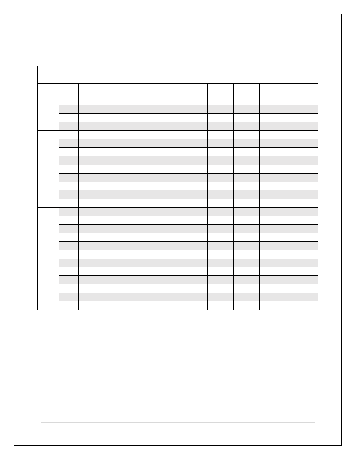
ES90LVP
Performance Data - Hot Water Capacities (BTUH) @ 70°F Entering Air Temperature
Entering Water Temperature
CFM
GPM
110°F
120°F
130°F
140°F
150°F
160°F
170°F
180°F
Water PD
feet WC
@140°F
600
3
18,930
23,720
28,530
33,350
38,180
43,020
47,860
52,710
1.96
4
19,890
24,920
29,960
35,010
40,070
45,140
50,210
55,280
3.26
5
20,500
25,670
30,850
36,040
41,240
46,440
51,650
56,860
4.84
700
3
20,890
26,190
31,510
36,840
42,180
47,540
52,900
58,260
1.96
4
22,140
27,740
33,360
38,990
44,640
50,290
55,940
61,600
3.26
5
22,930
28,720
34,520
40,340
46,170
52,000
57,840
63,690
4.84
800
3
22,630
28,380
34,150
39,940
45,750
51,560
57,380
63,210
1.96
4
24,170
30,300
36,450
42,610
48,790
54,970
61,160
67,360
3.26
5
25,160
31,520
37,910
44,300
50,710
57,130
63,550
69,980
4.84
900
3
24,180
30,340
36,520
42,720
48,930
55,160
61,400
67,640
1.96
4
26,030
32,630
39,260
45,910
52,570
59,250
65,930
72,610
3.26
5
27,220
34,110
41,030
47,960
54,900
61,860
68,820
75,790
4.84
1,000
3
25,580
32,100
38,640
45,210
51,790
58,400
65,000
71,620
1.96
4
27,720
34,770
41,840
48,930
56,040
63,160
70,290
77,430
3.26
5
29,120
36,510
43,910
51,340
58,780
66,240
73,700
81,170
4.84
1,100
3
26,830
33,680
40,550
47,450
54,370
61,310
68,260
75,210
1.96
4
29,270
36,720
44,200
51,700
59,210
66,750
74,290
81,840
3.26
5
30,880
38,720
46,590
54,480
62,380
70,310
78,240
86,170
4.84
1200
3
27,970
35,110
42,280
49,480
56,710
63,950
71,200
78,460
1.96
4
30,700
38,520
46,370
54,240
62,140
70,050
77,980
85,910
3.26
5
32,520
40,790
49,080
57,400
65,730
74,090
82,450
90,830
4.84
1,300
3
28,990
36,400
43,850
51,320
58,820
66,340
73,860
81,400
1.96
4
32,020
40,170
48,370
56,590
64,840
73,100
81,380
89,670
3.26
5
34,050
42,710
51,400
60,120
68,860
77,620
86,380
95,170
4.84
Page 9
8 | P a g e
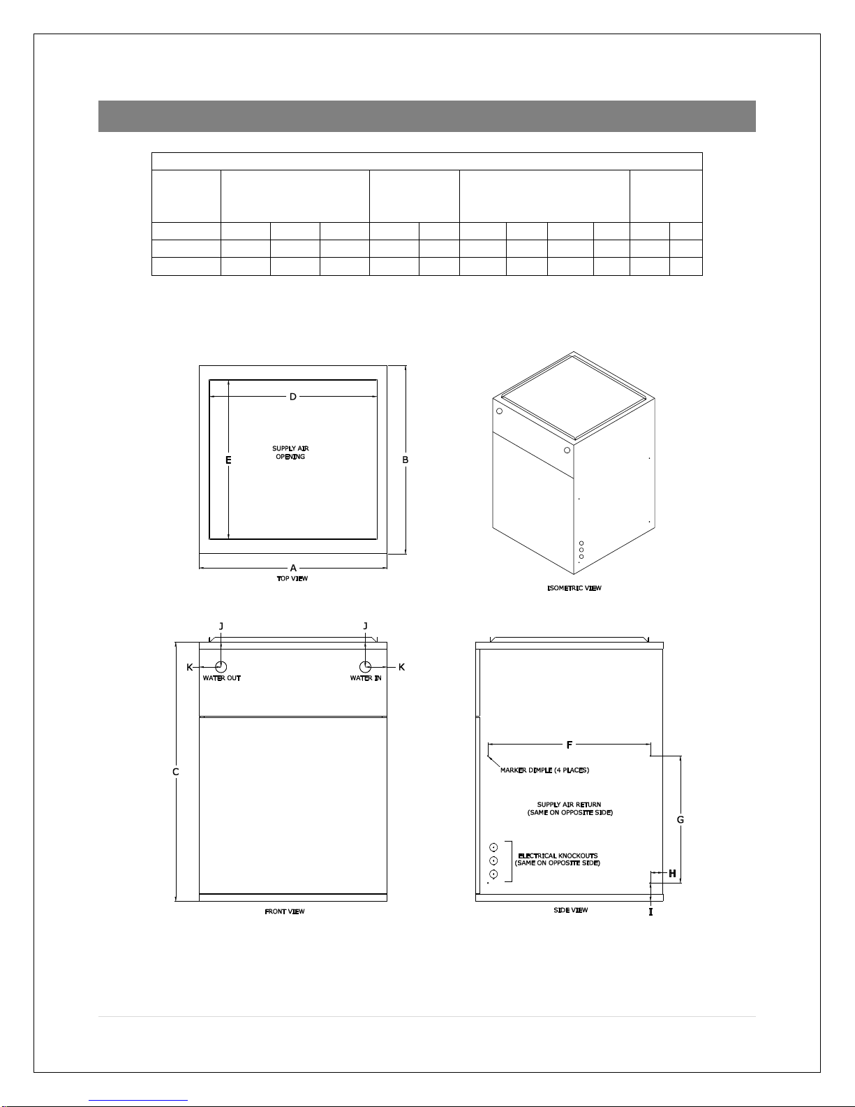
SPECIFICATIONS
PHYSICAL DATA - INCHES
Model
Overall Dimensions
W x D x H
Supply
Opening
W x D
Side Return
Piping
Location
A B C D E F G H I J K ES50LVP
14.0
21.0
29.0
11.8
17.8
18.3
14.3
1.4
2.0
2.8
2.4
ES90LVP
21.0
21.0
29.0
18.8
17.8
18.3
14.3
1.4
2.0
2.8
2.4
Page 10

9 | P a g e
MODEL
ES50LVP
ES90LVP
DX Cooling Capacity (tons)
1 to 2
1.5 to 3.5
Power (Volts/Phase/Hz)
120/1/60
120/1/60
Cabinet Size W x D x H (in)
14 x 21 x 29
21 x 21 x 29
Supply Air Opening W x D (in)
11.8 X 17.8
18.8 x 17.8
Side Return Air Opening (in)
18.3 X 14.3
18.3 X 14.3
Recommended Filter Size (in)
16 x 20
16 x 20
Shipping Weight (lb)
85
95
Shipping Dimensions W x D x H (in)
15 x 24 x 30.5
22 x 24 x 30.5
ES50LVP ECM blower performance (CFM/amps)
SWITCH
SETTING
0.1” WC
0.2” WC
0.3” WC
0.4” WC
0.5” WC
300 CFM
298
0.36
315
0.55
338
0.70
342
0.91
348
1.1
400 CFM
352
0.45
384
0.66
392
0.85
408
1.04
411
1.22
500 CFM
478
0.7
491
0.92
497
0.95
511
1.34
519
1.56
600 CFM
615
1.13
624
1.35
630
1.61
643
1.86
655
2.13
700 CFM
681
1.47
698
1.74
726
2.02
733
2.32
736
2.56
800 CFM
800
2.01
798
2.31
806
2.58
831
2.95
849
3.26
900 CFM
905
2.70
908
2.99
916
3.31
927
3.65
937
3.9
Page 11

10 | P a g e
ES90LVP ECM blower performance (CFM/amps)
SWITCH
SETTING
0.1” WC
0.2” WC
0.3” WC
0.4” WC
0.5” WC
600 CFM
603
0.82
607
1.02
610
1.25
618
1.49
620
1.7
700 CFM
681
1.04
688
1.26
699
1.47
702
1.76
708
1.99
800 CFM
756
1.22
782
1.58
800
1.92
823
2.28
844
2.58
900 CFM
874
1.7
894
2.08
918
2.44
927
2.82
940
3.11
1000 CFM
1000
2.31
1022
2.76
1034
3.14
1045
3.53
1060
3.89
1100 CFM
1120
3.07
1133
3.5
1145
3.93
1153
4.38
1170
4.8
1200 CFM
1195
3.56
1205
4.07
1211
4.5
1223
4.9
1228
5.38
1300 CFM
1282
4.32
1286
4.74
1295
5.2
1305
5.73
1312
6.17
QUICK START-UP PROCEDURES
Refer to the superseding installation instructions before following the start-up procedures.
1. Fill the system with water. Do not start the system.
2. Purge all air from the system. Isolation and purge valves are strongly recommended.
3. Purge all air from the space heating loop by closing the isolation valve on the return leg
of the loop and open the drain to purge air. Open the return leg isolation valve and
then close the drain valve.
4. Start the hot water generating equipment per the manufacturer’s recommendations.
Set the design water temperature to deliver the necessary amount of BTUs to the air
handler.
Page 12

11 | P a g e
5. Once all air has been purged, turn on the power to the ecosmart and set the room
thermostat to heat and set the temperature high enough to initiate a call for heat. This
will energize the air handler an in turn the fan and pump.
6. Once the heat source is supplying hot water, check supply and return pipes for a
temperature difference to make sure there is flow. There should be a noticeable
difference in temperature between supply and return lines. Use caution when supply
water temperature is above 120 F / 49 C.
INSTALLATION
The installer must comply with all local and national code requirements pertaining to the
installation of this equipment.
Clearances
The ecosmart is approved for up-flow, down-flow, and horizontal configurations. Clearances do
not change with orientation. This hydronic furnace is for indoor installation only.
Clearance from
Combustibles (in)
Recommended Service
Clearance (in)
Top
0
0
Bottom 0 0
Front 0 24
Back
0
0
Sides 0 0
Freeze Protection
It is not recommended to install the ecosmart in an unheated space.
Should the ecosmart be installed in an area where the ambient temperature may fall below
freezing, ethylene or propylene glycol should be added into the hydronic heating system to
protect against damage, which would not be covered under warranty. Make sure the glycol is
compatible with all system components and is permitted by local and national codes.
Page 13

12 | P a g e
Rear Piping Connections
The heating coil may be reversed to allow rear piping:
• Remove upper door
• Disconnect supply air sensor from extension cable
• Slide out heating coil
• Re-mount supply air sensor and grommet to opposite end of heating coil
• Remove rear knock-outs
• Slide in heating coil
• Use plastic plugs (provided) to close up holes on upper door
Ecosmart Mounting
The ecosmart can be installed in up flow, down flow and left or right horizontal applications.
Install the ecosmart with the door in place to make sure the cabinet remains square. Flip the
unit for down flow applications so that the top of the unit is now the bottom. No modification is
required for any configuration.
The ecosmart can be suspended from floor joists, rafters or concrete using rods, pipe, angle
supports or straps. Units must be hung level to ensure quiet operation.
CAUTION - Use any of the existing screw holes in the cabinet when using straps. If
the existing screw is too short for securing a mounting strap, a longer screw should
be used provided care is taken not to damage any internal components. Product
warranty does not cover any damage or claims resulting from damage from longer
screws or from the unit being improperly suspended.
The cabinet is designed so that the return air can be located on either side of the cabinet, or
from the bottom of the cabinet. Position a filter rack so that the filter is readily accessible. A
filter and filter rack are not included. Sides are marked for a standard 16 x 20 in filter rack.
WARNING - Special care should be taken in the vicinity of the coil to avoid
puncture. Screw into opening flange instead of top of cabinet when fastening the
supply air duct.
Plumbing
Install a sediment faucet or ball valve for use as a drain/purge valve. The drain valve must be
located downstream of the pump and check valve, and upstream of the isolation valve (if
Page 14

13 | P a g e
isolation valve is present). With this arrangement, any air trapped in the system can easily be
flushed out following the instructions in the Start-up & Troubleshooting sections.
Isolation valves are recommended ease of servicing.
When the space heating loop connections are made to the domestic water connections:
• The heating loop connections should be positioned horizontally in a vertical section of
the domestic water line for both inlet and outlet. Refer to the piping schematic for
details.
• Connect the heating loop to the domestic water connections as close to the water
heater as possible
Avoid sections of pipe in the heating loop that can trap air where possible. It is usually
impossible to install a system without having at least one part of the system or heating coil able
to trap air. This will not be a problem if the connection to the domestic water lines is made
properly, and purge valves and air eliminator devices are installed.
• Following the flushing procedures in the Start-up section will ensure that there is no air
in the system after initial set-up.
Follow recommendations supplied by the manufacturer of the heating source being used.
ecosmart includes a flow switch connection where a flow switch can be connected to allow for
domestic water priority. Note: the correct type of flow switch is a normally open (NO) device.
The flow switch closes when domestic water is flowing.
Check Valve
A check valve may be required for your system to meet local codes and to work effectively. A
check valve:
• Protects against back-flow of water to avoid short circuiting around the water heater
during domestic use
• Protects against thermal siphoning
• Is required in all potable water systems
Pump
A pump is not included inside the ecosmart. Whether you are using an external pump or an
internal built-in pump, it should be sized for the system. Pumps supplied with the heat
generating units can be used as the sole pump provided it meets the needs of the system. This
Page 15

14 | P a g e
is especially the case in retrofit applications where a much larger pump may have previously
been used in the system.
The ecosmart includes a built-in variable speed pump controller that can control a standard
single speed pump up to 250 watts. Operational modes are as follows:
• When set up in modulating mode, the pump will operate as a continuously variable
speed pump
• When set up in step-modulating mode, the pump will operate as a multi-speed pump.
• When set up in basic mode, the pump will operate as a single-speed pump
• The ecosmart controller has a built-in pump timer that exercises the pump for 1 minute
every 24 hours to prevent the possibility of ‘sticking’ due to sediment and local codes
Water Heater or Boiler Setup
Follow the manufacturer’s installation and start-up instructions of the water heater or boiler.
Make sure the equipment is turned off during installation and service. Make certain the
equipment has been refilled and all air is purged from the system before turning on the heater.
WARNING - When the system requires water temperatures higher than 120F,
a mixing valve shall be installed to reduce domestic hot water temperature to
safeguard against scalding.
Combo Systems
The ecosmart is ideal for use in combo systems which provide space heating and domestic hot
water from a single heat source. Any properly sized gas, propane or oil fired water heater or
boiler will work in a combo system. Make sure any water heater being used is approved for
combo applications.
Page 16

15 | P a g e
PIPING DIAGRAMS
Tankless Water Heater Piping
Page 17

16 | P a g e
Combi-Boiler Piping
Page 18

17 | P a g e
ELECTRICAL
• WARNING - Make sure the installation meets all national and local
electrical codes.
Electrical Information
The ecosmart wiring diagram is located on the cover of the electrical box behind the lower front
panel. Ratings data is located on the lower front panel.
• The ecosmart operates on 120VAC 60Hz single phase line voltage
• All control circuits are standard 24VAC
• ecosmart must be grounded via the green wire within the control box
Electrical Connections Made to Quick Connects
• Stranded or solid wire may be used
• Male tab size on control board: 0.250 in x 0.032 in
• Correct female disconnects to mate with male tabs:
o Wire range: 22-18 AWG (Red) Panduit # DNF18-250 or equivalent
Wire range: 16-14 AWG (Blue) Panduit # DNF14-250 or equivalent
• Use a quality ratchet crimping tool to ensure reliable connections
Page 19

18 | P a g e
Thermostat Wiring
Any standard heat/cool thermostat is compatible with the ecosmart.
Wire thermostat to lower right tabs as marked. The ecosmart supports optional 2-stage cooling
if required.
Page 20

19 | P a g e
Ecosmart ES50LVP/ES90LVP Wiring Diagram
Page 21

20 | P a g e
Miscellaneous Wiring
Miscellaneous wiring to the upper right tabs of control board as marked:
• FLOW – When using a water heater and domestic water priority is required, connect a
normally open (NO) flow switch. If there is a call for DHW, fan and pump will shut down
after 1 minute. If flow switch is active longer than 30 minutes, fan and pump will resume
normal operation.
• BOILER – dry contacts to initiate heat source
• AUX 24V – 24VAC output for humidifier or other accessory. Active when heating is on
• OUTDOOR – included outdoor temperature sensor connects here. If sensor is not
connected, ecosmart assumes coldest temperature is present and will not modulate fan
and pump
Page 22

21 | P a g e
DIP SWITCH OPTIONS
Switch Locations
Four DIP switches are located on the top, mid-section of the control board.
WARNING – to prevent damage, use a small screwdriver to change switch position.
Up is ON as marked on the switch body and are identified with numbers below.
• OUTDOOR TEMP – set the lowest outdoor temperature expected
• HEAT CFM – set 1 of 8 fan CFM rates for heating
• SYSTEM – set various system parameters
• COOL CFM – set 1 of 8 fan CFM rates for cooling
Outdoor Temperature Select
Select lowest possible expected outdoor temperature.
DESIGN TEMP °C
DESIGN TEMP °F
SWITCH 1
SWITCH 2
SWITCH 3
< -18
< 0
OFF
OFF
OFF
-17 to -10
1 – 14
ON
OFF
OFF
-9 to 0
15 – 32
OFF
ON
OFF
1 to 10
33 – 50
ON
ON
OFF
>10
>50
OFF
OFF
ON
NOT USED
X X X
NOT USED
X X X
NOT USED
X X X
Page 23

22 | P a g e
Heat CFM (ES90LVP)
Select required heating CFM.
CFM @ 0.5” WC
SWITCH 1
SWITCH 2
SWITCH 3
600
OFF
OFF
OFF
700
ON
OFF
OFF
800
OFF
ON
OFF
900
ON
ON
OFF
1000
OFF
OFF
ON
1100
ON
OFF
ON
1200
OFF
ON
ON
1300
ON
ON
ON
Heat CFM (ES50LVP)
Select required heating CFM.
CFM @ 0.5” WC
SWITCH 1
SWITCH 2
SWITCH 3
300
OFF
OFF
OFF
400
ON
OFF
OFF
500
OFF
ON
OFF
600
ON
ON
OFF
700
OFF
OFF
ON
800
ON
OFF
ON
900
OFF
ON
ON
System (ES990LVP and ES50LVP)
Select required system parameters.
Mode
SWITCH 1
SWITCH 2
SWITCH 3
SWITCH 4
Full Modulation
OFF
OFF X X
Step Modulation
ON
OFF X X
Single Stage
OFF
ON X X
Test Mode (1)
ON
ON X X
Normal Fan Cooling (2)
X X OFF X Dehumidification Fan Cooling (2)
X X ON X Normal Continuous Fan (3)
X X X
OFF
Low Speed Continuous Fan (3)
X X X
ON
Page 24

23 | P a g e
(1) Test Mode - heat source is brought on, fan runs at HEAT CFM setting and pump runs at full
speed irrespective of thermostat setting. Useful for eliminating air in the system during
installation.
(2) Normal Fan Cooling runs at rate set by COOL CFM switch.
Dehumidification Fan Cooling runs at 85% of COOL CFM rate for 10 min. and then reverts back
to rate set by COOL CFM.
(3) Normal Continuous Fan runs at rate set by HEAT CFM switch.
Low speed Continuous Fan runs at 50% of rate set by HEAT CFM switch.
Cool CFM (ES90LVP)
CFM @ 0.5” WC
SWITCH 1
SWITCH 2
SWITCH 3
600
OFF
OFF
OFF
700
ON
OFF
OFF
800
OFF
ON
OFF
900
ON
ON
OFF
1000
OFF
OFF
ON
1100
ON
OFF
ON
1200
OFF
ON
ON
1300
ON
ON
ON
Cool CFM (ES50LVP)
CFM @ 0.5” WC
SWITCH 1
SWITCH 2
SWITCH 3
300
OFF
OFF
OFF
400
ON
OFF
OFF
500
OFF
ON
OFF
600
ON
ON
OFF
700
OFF
OFF
ON
800
ON
OFF
ON
900
OFF
ON
ON
Page 25

24 | P a g e
SEQUENCE OF OPERATION
Full Modulation
Heating Mode – (ecosmart outdoor sensor installed)
Thermostat calls for heat
• R is connected to W
• Heat generator is turned on
• Auxiliary 24VAC power is turned on
• Pump turns on 100%
• After a 15 second delay to allow for system water to heat up coil, fan ramps up to HEAT
CFM speed
• ecosmart control automatically adjusts fan and pump speeds to meet the outdoor
temperature conditions
Thermostat is satisfied
• R is disconnected from W
• Heat generator is turned off
• Auxiliary 24VAC power is turned off
• Pump turns off and fan speed ramps down to zero, extracting any remaining heat in the
coil
Step Modulation
Heating Mode – (ecosmart outdoor sensor not installed)
Thermostat calls for heat
• R is connected to W
• Heat generator is turned on
• Auxiliary 24VAC power is turned on
• Pump turns on 100%
• After a 15 second delay to allow for system water to heat up coil, fan ramps up to HEAT
CFM speed
• ecosmart goes through three steps:
• 50% of HEAT CFM setting for 5 minutes – pump LO
• 75% of HEAT CFM for 5 minutes – pump MID
• 100% of HEAT CFM until thermostat is satisfied – pump HI
Page 26

25 | P a g e
Thermostat is satisfied
• R is disconnected from W
• Heat generator is turned off
• Auxiliary 24VAC power is turned off
• Pump turns off and fan speed ramps down to zero, extracting any remaining heat in the
coil
Basic Modulation Mode
Heating Mode – (ecosmart outdoor sensor not installed)
Thermostat calls for heat
• R is connected to W
• Heat generator is turned on
• Auxiliary 24VAC power is turned on
• Pump turns on at 100%
• After a 15 second delay to allow for system water to heat up coil, fan ramps up to HEAT
CFM speed
Thermostat is satisfied
• R is disconnected from W
• Heat generator is turned off
• Auxiliary 24VAC power is turned off
• Pump turns off and fan speed ramps down to zero, extracting any remaining heat in the
coil
Cooling Mode (Modulation, Step and Basic)
(ecosmart outdoor sensor not installed)
(Assumes a condenser and DX coil is installed within the system)
• R is connected to Y or Y2*
• Condenser turns on
• Fan ramps up to COOL CFM setting
* If thermostat and condenser support 2-stage cooling
Page 27

26 | P a g e
Thermostat is satisfied
• Condenser turns off
• Fan speed ramps down to zero, extracting any remaining cooling from the DX coil
Dehumidification
When in cooling mode, a dehumidification function can be set using system switch 3 as follows:
• OFF - Normal cooling fan runs at rate set by COOL CFM switch
• ON - fan runs at 85% of COOL CFM rate for 10 min. and then reverts back to rate set by
COOL CFM
Fan Mode
• R is connected to G
• If fan is set to “ON” on thermostat, fan runs as follows:
• If SYSTEM switch 4 is OFF, fan runs at selected HEAT CFM rate
• If SYSTEM switch 4 is ON, fan runs at 50% of selected HEAT CFM rate
• If fan is set to “OFF” on thermostat, fan runs at HEAT or COOL CFM settings
Constant Low Fan Circulation
Fan may be run at a low rate using system switch 4 as follows:
• OFF – fan runs at rate set by HEAT CFM switch
• ON – fan runs at 50% of rate set by HEAT CFM switch
Freeze Protection
The ecosmart is equipped with a freeze protection sensor to help prevent any damage to the
hot water coil from a freeze up. In any mode, heating, cooling or standby, when the outlet air
temperature sensor reads a temperature of 40°F or lower the ecosmart will bring on the
circulating fan and energize the pump relay.
Page 28

27 | P a g e
Pump Exerciser
• The circulating pump is exercised for 1 min every 24 hr when the ecosmart is OFF,
COOLING (Y), COOLING2 (Y2) or FAN (G) to prevent the possibility of ‘sticking’ due to
sediment and to meet local codes.
• During the 1 min pump on-time, the fan is turned off and resumes once the pump
exercising is completed
• Pump runs continuously if the outlet air temperature drops below 40F to prevent the
chance of freezing
SERVICE AND MAINTENANCE
NOTE: The ecosmart is not to be used for temporary heat during construction. Use for this
purpose will void equipment warranty.
Filter
Inspect the filter monthly and replace, remove and vacuum or rinse as required. A clogged or
inadequate filter may void product warranty. Replacement filter size is 16 x 20 x 1.
Coils
Air conditioning and heating coils should not require cleaning if the filter maintenance schedule
is adhered to. If a filter is damaged or collapses from plugging, dust may foul the coils. If this
happens, replace the filter and carefully vacuum the coils. The fan may need to be removed to
gain access to the face of the heating coil.
Fan and Motor
Check fan for dust once a year. If dirty, vacuum or wash to remove dust. Keeping the fan blades
clean will reduce noise and improve capacity and efficiency of the heating system.
Control and Blower Assembly Removal
1. Turn off main power.
2. Disconnect power, thermostat and any other miscellaneous wiring from the control
board and remove them from the control casing.
Page 29

28 | P a g e
3. On the bottom side of the upper cover, disconnect the supply air temperature sensor by
sliding out the rubber grommet.
4. Gently pull out the black wire until a white connector is revealed.
5. Unplug the white connector noting that there is a polarizing/locking feature when re-
assembling.
6. Remove (Qty. 2) ¼-20 bolts, lockwashers and flat washers holding the control and
blower assembly to the centre plate.
7. Slide out assembly.
8. Re-assemble in the reverse order.
TROUBLESHOOTING
Thermostat call error
If the ecosmart does not run when the thermostat is calling, jumper R to W for heating, or R to
Y (Y2) to verify if the problem is with the thermostat or ecosmart control. Note that some
thermostats have a delay (typically five minutes) before they will re-start cooling.
External pump does not run
In areas where hard water is present the pump may stick and fail to run. Often, closing the
isolation valve on the return leg and opening the drain port so that water flows through the
pump can free this. If this fails to free the pump, removal for cleaning or replacement is
necessary. The daily pump exerciser will help prevent pump sticking.
External pump is noisy at start-up
If sound has not diminished within 1 minute, air may be present in the system and may need repurging. If the heat source is a water heater, check to make sure branch connections for the
heating loop are horizontal to prevent the collecting of air in the loop.
Water heater temperature and pressure relief valve is weeping
A check valve or back-flow preventer may have been installed in the system. Some form of
pressure relief may be required. Consult water heater manufacturer’s instructions. An
expansion tank may be required.
Page 30

29 | P a g e
Insufficient or no heat
• Check that the heat generator is functioning properly.
• Plugged air filter or coil. Refer to maintenance section for filter care and coil cleaning.
• Air in heating loop - purge system.
• Inlet and outlet connections to ecosmart are backwards - reverse connections.
• Supply water temperature set too low or heat generator is not supplying water at the
specified setting.
• Restrictions on heating loop - remove restrictions, check if valve is stuck, isolation valves
could be too restrictive or left partially closed after purging, or a closed valve.
Cold water at hot faucet
When the heat source is a water heater, the most probable cause is reverse flow through the
heating loop from a stuck check valve - repair or replace valve.
Fan runs for cooling but not for heating
The room thermostat may be connected improperly. Refer to Electrical section or wiring
schematic on ecosmart for proper installation.
Heating during standby mode
Probable cause is thermal siphoning.
WARRANTY
Warranty is 2 years’ parts. Visit ecosmartair.com/warranty.htm for full details.
 Loading...