

EcoSmart ES50HVP, ES90HVP Service Manual

P/N 14010A
ES50HVP / ES90HVP
HIGH VELOCITY AIR HANDLER
Service Manual
Ecosmartair
105 Haist Avenue, Unit 10
Vaughan, ON L4L 5V6
905-857-9755
ecosmartair.com

1 | P a g e

2 | P a g e
Contents
CONTROL ASSEMBLY LAYOUT ............................................................................................ 3
CONTROL ASSEMBLY LEGEND ............................................................................................ 4
REMOVING BLOWER/CONTROL ASSEMBLY ...................................................................... 5
TROUBLESHOOTING .............................................................................................................. 5
Smart/WiFi thermostat not working properly ...................................................................................... 5
Thermostat call error ............................................................................................................................ 6
Fan not running ..................................................................................................................................... 6
Fan runs for cooling but not for heating ............................................................................................... 6
External pump does not run (sticking issue) ......................................................................................... 6
External pump does not run (electrical issue) ...................................................................................... 7
External pump is noisy at start-up ........................................................................................................ 7
Water heater temperature and pressure relief valve is weeping ........................................................ 7
Insufficient or no heat ........................................................................................................................... 7
Cold water at hot faucet ....................................................................................................................... 7
Heating during standby mode .............................................................................................................. 8
Pump and fan run continuously (test mode off and no call for heat/cool) .......................................... 8
Constant Pressure Sensing (CPT™) not working ................................................................................... 8
Final Assembly – Exploded View ......................................................................................................... 10
Electrical Box – Exploded View ........................................................................................................... 11
Blower & Heating Coil – Exploded View ............................................................................................. 12
Replacement Parts .............................................................................................................................. 13
All technical information subject to change without notice.
3 | P a g e
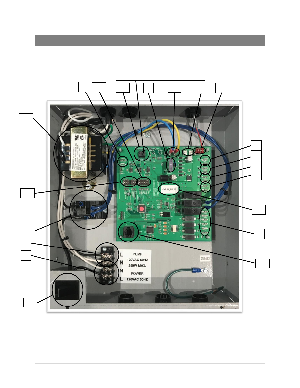
CONTROL ASSEMBLY LAYOUT
Figure 1 - HVP Control Assembly
3
15
10
16
9
7
6
5 4 8
14
1
2
13
17
11
12
18
19
20
Tubing connects to right-hand port
4 | P a g e
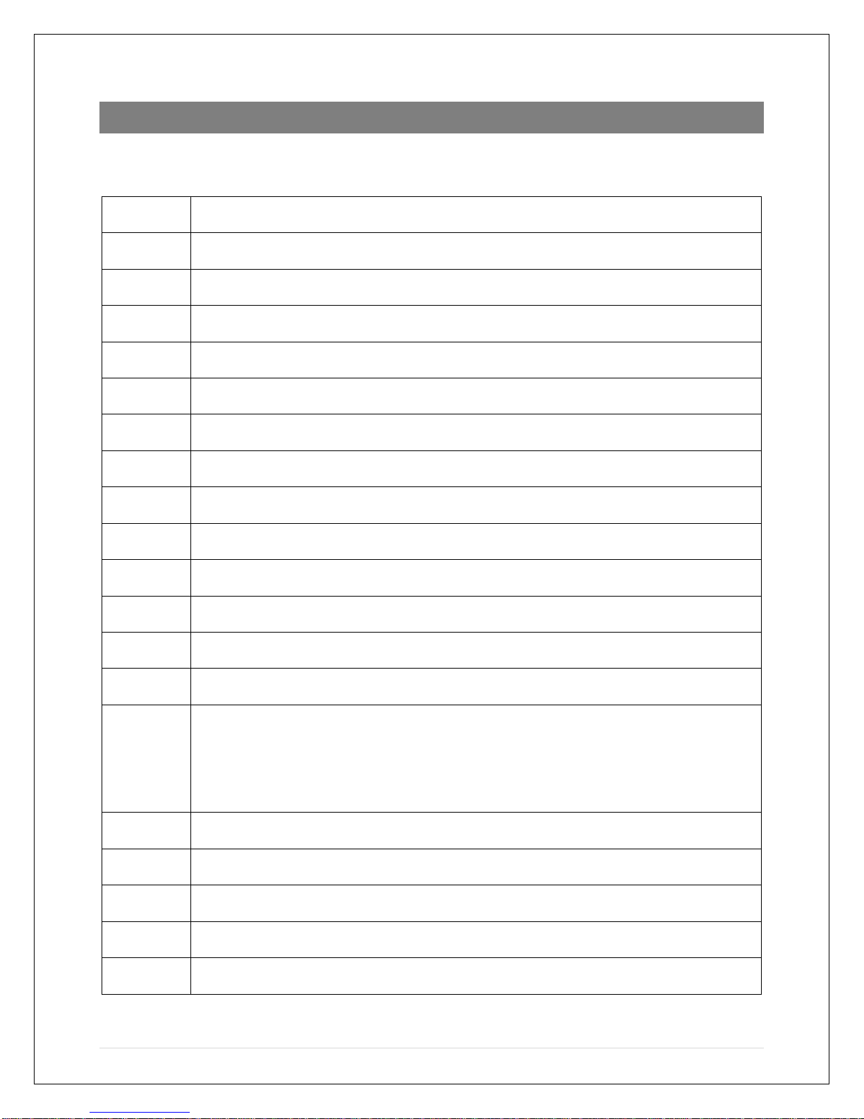
CONTROL ASSEMBLY LEGEND
Refer to Figure 1 (bolded numbers on left side are referred to in troubleshooting)
1
120VAC 60Hz single phase power input
2
120VAC 250W Max. pump output from relay
3
Thermostat connection: R, G, Y2, Y, W, interrupted C
4
0-10VDC output voltage for variable speed pump
5
Auxiliary 24VAC accessory output – active when heating
6
Dry contacts to bring on heat source
7
Flow switch input for domestic hot water priority
8
Air in/out temperature sensors
9
Fuse 3A 32V ATO type
10
Pressure sensor
11
Heat/cool CFM DIP switches
12
Options DIP switches
13
Door switch
14
Pump relay
15
24VAC output from transformer: Blue = R, Yellow = C*
* For smart/WiFi thermostats requiring constant power such as Nest, Ecobee,
CÔR etc., use C connection at yellow wire using a double male/female adapter
0.25”. Do not connect thermostat to C terminal in 3 above – this is only active
when the A/C condenser is on
16
24VAC 40VA transformer
17
Software version identifier
18
Building automation system input
19
Variable speed output to EC motor
20
Diagnostic connector
 Loading...