

ECOScience 6300wt, ControlScience 300, 6500wt, 8500wt, 8750wt Installation And User Manual
...
ECOScience ENERGY CENTRE
Installation
and
User Manual
Top Connected System Tank
Control System: CS300
6300wt, 6500wt, 8500wt, 8750wt
Edition: 01; Last updated: 2011-04-12


ECOScience ENERGY CENTRE
Congratulations on choosing this ECOScience
product
We are confident that this product will meet all your expectations, both in
terms of climate comfort and energy savings. Choosing one of our
products also shows your commitment and concern for our shared
environment.
Whatever product or package you have chosen, you will be at the
absolute forefront of technology in terms of efficient energy use. If you
have chosen an individual energy centre such as the 6500i, this can
always be used directly to produce hot tap water and radiator heating via
the integrated 4.5 kW electric heaters.
You can add to your energy centre later with a range of add-on modules.
INSTALLATION AND USER MANUAL
The control system manages the add-on modules connected to the
centre using module key updates and at the same time ensures optimum
energy efficiency.
The control system is operated using a user-friendly colour touchscreen.
Managing Director
Mikael Jönsson
Edition: 01; Last updated: 2011-04-12
© ECOScience
i

ECOScience ENERGY CENTRE
INSTALLATION AND USER MANUAL
ii
© ECOScience
Edition: 01; Last updated: 2011-04-12

INSTALLATION CERTIFICATE
For warranty cover and to register the product with ECOScience.
PRODUCTS THAT HAVE BEEN INSTALLED:
Name:
Product number:
Date of installation:
THE PRODUCTS HAVE BEEN INSTALLED AT:
Name:
Address:
Postal address:
Telephone:
THE PRODUCTS WERE INSTALLED BY:
Company:
Address:
Postal address:
Telephone:
Installation engineer:
To be sent to:


ECOScience ENERGY CENTRE
TERMS OF WARRANTY
This is an extract from the ECOScience Terms of Warranty. See AA VVS
09 (general terms issued by industry associations) for full terms and
conditions. If the instructions set out in this documentation are not
followed, the obligations that would otherwise be incumbent upon
ECOScience under these terms shall not be binding. Due to the rapid
pace of development in the industry, we reserve the right to amend
specifications and modify parts.
• All products marketed by ECOScience are covered by a 2 year
warranty for design, manufacture and material defects that
commences from the date of installation.
• For the duration of the warranty, the installation engineer
undertakes to rectify any defects that occur, either by repairing and/
or replacing the product.
• If the purchaser wishes to resolve any defects himself, the product
must be examined beforehand by us or by a person we have
appointed. A separate agreement may be entered into regarding
repairs and costs.
INSTALLATION AND USER MANUAL
• In the event of a defect, the installation engineer must be contacted
first.
• A defect means any departure from the normal standard, assessed
by an industry professional. Defects or deficiencies that occur due
to abnormal circumstances, such as mechanical or environmental
circumstances, shall not fall under the scope of the warranty.
• ECOScience shall therefore not be liable if the defect is attributed
to abnormal or varying water quality, such as chalky or aggressive
water, variations in electrical voltage or other electrical interference.
• Nor shall ECOScience be liable for defects if the installation and/or
maintenance instructions have not been followed.
• The product must be examined thoroughly on delivery. Any defects
discovered must be reported before the product is used. All defects
must be reported immediately.
• ECOScience shall not be liable for defects that have not been
reported within 2 years of the date of installation.
• ECOScience shall not be liable for ‘indirect’ damage/loss, including
damage to entities other than the product, for example personal
injury, damage to physical property or losses caused by operational
stoppage etc..
Edition: 01; Last updated: 2011-04-12
© ECOScience
• Nor shall ECOScience be liable for compensation in the event of
any increase in energy consumption caused by a defect in the
product or the installation. For the rest, the provisions set out in AA
VVS 09 apply.
• If the product requires modification or to be serviced by a
professional, consult your installation engineer who will undertake
any necessary adjustments.
• When reporting defects, please state the product production
number, date of installation and details of the installation engineer.
v

ECOScience ENERGY CENTRE
RESPONSIBILITY
The installation engineer is responsible for ensuring that these
instructions are followed and that the environment and the methods
used when the control system is installed, commissioned and operated,
are correct. If these instructions are ignored, costly material damage
and/or serious personal injury may result.
Due to the foregoing, neither the manufacturer nor the supplier of this
product shall be liable for losses, damage or other costs incurred as a
result of incorrect installation and/or commissioning, operation or
maintenance work.
The manufacturer and/or the supplier of this product reserves the right to
amend and/or update, without notice, the composition of the product, its
specifications, technical information and/or the accompanying
installation and operation manual.
If the control system becomes damaged, or deficiencies are discovered
that may put safety and/or operation at risk, the system must be
switched off immediately and the installation engineer called in.
INSTALLATION AND USER MANUAL
vi
© ECOScience
Edition: 01; Last updated: 2011-04-12

ECOScience ENERGY CENTRE
This user manual forms part of the product documentation in
accordance with the EU’s Pressure Equipment, Electromagnetic
Compatibility and Low Voltage Directives.
This manual is intended for installation engineers and users.
The person responsible must ensure that they have read and
understood the manual and the information in the included
documentation. Particular attention must be paid to the sections on
product and personal safety.
The manual should be kept in an easily remembered and accessible
place and should be consulted even if the slightest doubt exists.
The manufacturer assumes no liability for injury to persons or animals,
damage to property or damage to the product itself that occur as a result
of incompetent handling, are caused by failure to adequately observe
the safety instructions set out in this manual, or by modifying the product
or using unsuitable spare parts.
© 2010
INSTALLATION AND USER MANUAL
Copyright to the manual is held exclusively by
Fueltech Sweden AB
Fridhemsvägen 15
372 25 Ronneby, Sweden
This manual may only be reproduced or provided to a third party with
written consent. This also applies if extracts from the manual are to be
copied or passed on.
Edition: 01; Last updated: 2011-04-12
© ECOScience
vii

ECOScience ENERGY CENTRE
INSTALLATION AND USER MANUAL
viii
© ECOScience
Edition: 01; Last updated: 2011-04-12

ECOScience ENERGY CENTRE
Contents
1 BASIC INFORMATION . . . . . . . . . . . . . . . . . . . . . . . . . . . .1
1.1 ABOUT THE MANUAL . . . . . . . . . . . . . . . . . . . . . . . . . . . . 1
1.1.1 Explanation of Warnings. . . . . . . . . . . . . . . . . . . . . . .1
1.1.2 Important information . . . . . . . . . . . . . . . . . . . . . . . . .2
1.1.3 Changes and updates. . . . . . . . . . . . . . . . . . . . . . . . .2
1.2 INSTALLATION ENGINEERS . . . . . . . . . . . . . . . . . . . . . . . 2
1.3 ECOSCIENCE Energy Centre. . . . . . . . . . . . . . . . . . . . . . . 3
1.3.1 Description . . . . . . . . . . . . . . . . . . . . . . . . . . . . . . . . .3
1.3.2 Manufacturer. . . . . . . . . . . . . . . . . . . . . . . . . . . . . . . .3
1.4 PRODUCT MARKING . . . . . . . . . . . . . . . . . . . . . . . . . . . . . 3
1.4.1 Identification plate. . . . . . . . . . . . . . . . . . . . . . . . . . . .4
1.4.2 EC declaration of conformity. . . . . . . . . . . . . . . . . . . .4
2 SAFETY INSTRUCTIONS . . . . . . . . . . . . . . . . . . . . . . . . .5
2.1 GENERAL HAZARDS . . . . . . . . . . . . . . . . . . . . . . . . . . . . . 5
2.1.1 Space required . . . . . . . . . . . . . . . . . . . . . . . . . . . . . .5
2.1.2 Risks involving spare parts. . . . . . . . . . . . . . . . . . . . .5
INSTALLATION AND USER MANUAL
3 DESCRIPTION OF FUNCTIONS . . . . . . . . . . . . . . . . . . . .6
3.1 GENERAL . . . . . . . . . . . . . . . . . . . . . . . . . . . . . . . . . . . . . . 6
3.1.1 System tank . . . . . . . . . . . . . . . . . . . . . . . . . . . . . . . .7
3.1.2 Energy central unit . . . . . . . . . . . . . . . . . . . . . . . . . . .7
3.1.2.1 Tap water circuit . . . . . . . . . . . . . . . . . . . . .7
3.1.2.2 Solar loading circuit . . . . . . . . . . . . . . . . . . .7
3.1.2.3 Heat circuit . . . . . . . . . . . . . . . . . . . . . . . . . .8
3.1.3 Control system . . . . . . . . . . . . . . . . . . . . . . . . . . . . . .8
4 ASSEMBLY AND INSTALLATION . . . . . . . . . . . . . . . . . .9
4.1 BEFORE USE . . . . . . . . . . . . . . . . . . . . . . . . . . . . . . . . . . . 9
4.1.1 Safe disposal of packaging material. . . . . . . . . . . . . .9
4.2 GENERAL . . . . . . . . . . . . . . . . . . . . . . . . . . . . . . . . . . . . . 10
4.3 ASSEMBLING THE SUPPORT BASE AND
SYSTEM TANK . . . . . . . . . . . . . . . . . . . . . . . . . . . . . . . . . 11
4.3.1 Instructions . . . . . . . . . . . . . . . . . . . . . . . . . . . . . . . .11
4.4 CONNECTING THE PIPES. . . . . . . . . . . . . . . . . . . . . . . . 12
4.4.1 Please note. . . . . . . . . . . . . . . . . . . . . . . . . . . . . . . .12
4.4.2 Instructions . . . . . . . . . . . . . . . . . . . . . . . . . . . . . . . .12
4.4.3 Pipe connections . . . . . . . . . . . . . . . . . . . . . . . . . . .13
4.5 ASSEMBLY OF TEMPERATURE SENSORS
AND OVERHEAT PROTECTION . . . . . . . . . . . . . . . . . . . 16
4.5.1 Instructions . . . . . . . . . . . . . . . . . . . . . . . . . . . . . . . .16
4.6 ELECTRICAL INSTALLATION . . . . . . . . . . . . . . . . . . . . . 17
4.6.1 Please note. . . . . . . . . . . . . . . . . . . . . . . . . . . . . . . .17
4.6.2 Instructions . . . . . . . . . . . . . . . . . . . . . . . . . . . . . . . .17
4.7 FILLING THE SYSTEM WITH WATER . . . . . . . . . . . . . . . 18
4.7.1 Please note. . . . . . . . . . . . . . . . . . . . . . . . . . . . . . . .18
4.7.2 Instructions . . . . . . . . . . . . . . . . . . . . . . . . . . . . . . . .18
4.7.3 Connections and shut-off valves. . . . . . . . . . . . . . . .20
4.8 EMPTYING THE SYSTEM TANK . . . . . . . . . . . . . . . . . . . 21
4.8.1 Instructions . . . . . . . . . . . . . . . . . . . . . . . . . . . . . . . .21
Top connected system tank, CS300
Edition: 01; Last updated: 2011-04-12
© ECOScience
Contents 1 / 3

ECOScience ENERGY CENTRE
Contents
5 COMMISSIONING . . . . . . . . . . . . . . . . . . . . . . . . . . . . . . .22
5.1 PREPARATIONS BEFORE STARTING . . . . . . . . . . . . . . 22
5.2 START-UP. . . . . . . . . . . . . . . . . . . . . . . . . . . . . . . . . . . . . 22
5.3 NORMAL STOP. . . . . . . . . . . . . . . . . . . . . . . . . . . . . . . . . 22
6 CONTROL SYSTEM . . . . . . . . . . . . . . . . . . . . . . . . . . . . .23
6.1 START SCREEN (BASIC MODEL) . . . . . . . . . . . . . . . . . . 23
6.2 SYSTEM . . . . . . . . . . . . . . . . . . . . . . . . . . . . . . . . . . . . . . 24
6.3 SETUP. . . . . . . . . . . . . . . . . . . . . . . . . . . . . . . . . . . . . . . . 25
6.3.1 Modules . . . . . . . . . . . . . . . . . . . . . . . . . . . . . . . . . .25
6.3.2 Manual operation . . . . . . . . . . . . . . . . . . . . . . . . . . .26
6.3.3 Heat-up sequence . . . . . . . . . . . . . . . . . . . . . . . . . .27
6.3.4 Display settings. . . . . . . . . . . . . . . . . . . . . . . . . . . . .28
6.3.5 Calibrating the touchscreen . . . . . . . . . . . . . . . . . . .28
6.3.6 Restore default values . . . . . . . . . . . . . . . . . . . . . . .29
6.3.7 System information. . . . . . . . . . . . . . . . . . . . . . . . . .29
6.3.8 Activating DFU mode . . . . . . . . . . . . . . . . . . . . . . . .29
6.3.9 Calibrating the temperature sensors. . . . . . . . . . . . .30
6.4 DATE/TIME . . . . . . . . . . . . . . . . . . . . . . . . . . . . . . . . . . . . 32
6.5 STATUS TEMP.. . . . . . . . . . . . . . . . . . . . . . . . . . . . . . . . . 32
6.6 STATUS I/O. . . . . . . . . . . . . . . . . . . . . . . . . . . . . . . . . . . . 33
6.6.1 Explanation of ‘Status I/O’ menu . . . . . . . . . . . . . . .34
6.7 LANGUAGE. . . . . . . . . . . . . . . . . . . . . . . . . . . . . . . . . . . . 35
6.8 ALERTS/HISTORY . . . . . . . . . . . . . . . . . . . . . . . . . . . . . . 36
6.9 HEATING. . . . . . . . . . . . . . . . . . . . . . . . . . . . . . . . . . . . . . 37
6.10SOLAR CIRCUIT . . . . . . . . . . . . . . . . . . . . . . . . . . . . . . . . 38
6.11RADIATOR CIRCUIT. . . . . . . . . . . . . . . . . . . . . . . . . . . . . 38
6.11.1 Radiator circuit temperature curve . . . . . . . . . . . . . .39
6.11.2 Scheduled temperature changes in radiator circuit .40
6.11.3 Radiator circuit holiday settings . . . . . . . . . . . . . . . .41
6.12FLOOR HEATING CIRCUIT . . . . . . . . . . . . . . . . . . . . . . . 42
6.12.1 Floor heating circuit temperature curve . . . . . . . . . .43
6.12.2 Scheduled temperature changes in floor
6.12.3 Floor heating circuit holiday settings. . . . . . . . . . . . .45
6.13SOLID FUEL . . . . . . . . . . . . . . . . . . . . . . . . . . . . . . . . . . . 45
6.14BUFFER TANK . . . . . . . . . . . . . . . . . . . . . . . . . . . . . . . . . 45
6.15HEAT PUMP . . . . . . . . . . . . . . . . . . . . . . . . . . . . . . . . . . . 45
6.16POOL CONTROL . . . . . . . . . . . . . . . . . . . . . . . . . . . . . . . 45
INSTALLATION AND USER MANUAL
heating circuit . . . . . . . . . . . . . . . . . . . . . . . . . . . . . .44
7 MAINTENANCE . . . . . . . . . . . . . . . . . . . . . . . . . . . . . . . .46
7.1 MAINTENANCE AND FUNCTION CHECKS. . . . . . . . . . . 46
7.1.1 Regular maintenance to be carried out
at least once a year . . . . . . . . . . . . . . . . . . . . . . . . .46
7.2 CLEANING. . . . . . . . . . . . . . . . . . . . . . . . . . . . . . . . . . . . . 46
8 SERVICING AND REPAIRS . . . . . . . . . . . . . . . . . . . . . . .47
Top connected system tank, CS300
Edition: 01; Last updated: 2011-04-12
© ECOScience
Contents 2 / 4

ECOScience ENERGY CENTRE
Contents
9 TROUBLESHOOTING . . . . . . . . . . . . . . . . . . . . . . . . . . .48
9.1 COMMON FAULTS AND SOLUTIONS. . . . . . . . . . . . . . . 48
9.2 TABLE FOR RESISTANCE TEMPERATURE
SENSOR Pt 100 . . . . . . . . . . . . . . . . . . . . . . . . . . . . . . . . 49
9.3 ALERTS AND SOLUTIONS. . . . . . . . . . . . . . . . . . . . . . . . 50
9.3.1 Resetting overheat protection for electric heaters . .50
10 TECHNICAL DATA . . . . . . . . . . . . . . . . . . . . . . . . . . . . . .51
10.1TECHNICAL DATA, SYSTEM TANK. . . . . . . . . . . . . . . . . 51
10.2TECHNICAL DATA, ENERGY CENTRAL UNIT . . . . . . . . 51
10.3TECHNICAL DATA, CONTROL SYSTEM. . . . . . . . . . . . . 52
11 APPENDICES . . . . . . . . . . . . . . . . . . . . . . . . . . . . . . . . . .53
APPENDIX 1 - EC DECLARATION OF CONFORMITY
APPENDIX 2 - FLOW CHART
APPENDIX 3 - WIRING DIAGRAM AND TEMPERATURE
APPENDIX 4 - DEFAULT SETTINGS
APPENDIX 5 - LIST OF COMPONENTS
INSTALLATION AND USER MANUAL
SENSORS
Top connected system tank, CS300
Edition: 01; Last updated: 2011-04-12
© ECOScience
Contents 3 / 3

ECOScience ENERGY CENTRE
1 BASIC INFORMATION
1.1 ABOUT THE MANUAL
This manual contains instructions for installation, operation and safety
and is intended for installation engineers and other users of
ECOScience Energy Centre.
Read the manual carefully and make sure it is always on hand.
Failure to follow the instructions may cause serious personal injury or
damage to the product.
• Take note of all the information contained in the boxes marked
Danger! Warning! Caution! and Please note!
• Remember that any type of electrical equipment may be live.
• Servicing and maintenance: Servicing and maintenance must only
be carried out by qualified service engineers.
INSTALLATION AND USER MANUAL
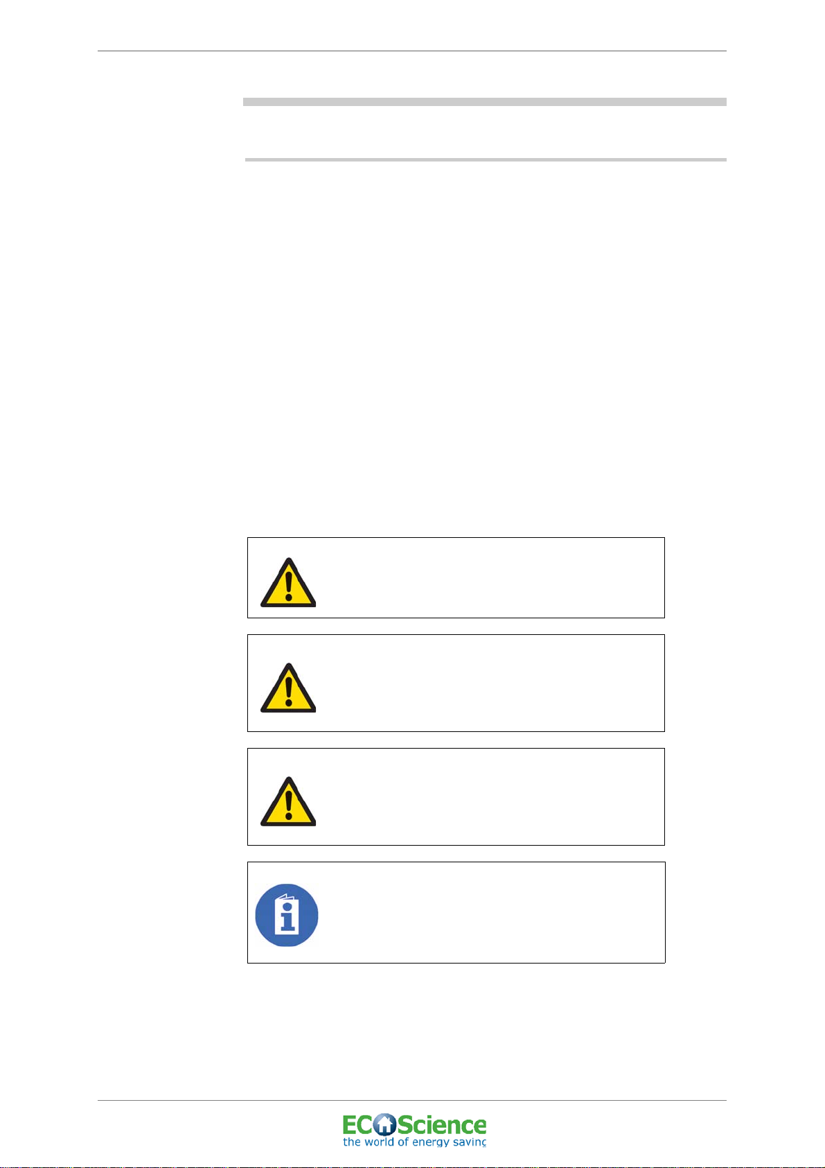
1.1.1 Explanation of Warnings
In this manual, boxes headed Danger!, Warning!, Caution! and Please
note! mean the following:
DANGER!
Ignoring this information could endanger life!
WARNING!
Ignoring this information may result in personal injury
or put life at risk!
CAUTION!
Ignoring this information may result in minor personal
injury or may damage the device!
PLEASE NOTE!
Information requiring particular attention!
Top connected system tank, CS300
Edition: 01; Last updated: 2011-04-12
© ECOScience
1

ECOScience ENERGY CENTRE
1.1.2 Important information
The following requirements are mandatory:
The manual and other useful documents must be kept for the entire
service life of the equipment.
This manual and other useful documents shall be regarded as part of the
equipment.
If the owner changes, the manual must be passed to the new owner or
user of the equipment.
The information in the manual must be updated if the product owner
makes additions to this equipment or other modifications.
In the event of conversion or redesign, a new risk analysis is required.
Any type of change must be approved by the product owner.
1.1.3 Changes and updates
If updates are implemented for the control system, the installation
engineer is responsible for ensuring that the manual is also updated, i.e.
that new instructions are added to the manual, replacing the old ones,
which are removed and discarded.
INSTALLATION AND USER MANUAL
The latest version of the installation and user manual for ECOScience
Energy Centre, and any updates/new instructions for the control system
are available to download from our website (http://www.ecoscience.se/
downloads.html).
1.2 INSTALLATION ENGINEERS
ECOScience Energy Centre must only be installed by certified
installation engineers who have the necessary theoretical and practical
training.
After installation, the installation engineer must:
• Fill in the table with the programmed values.
• Walk through the system with the end user.
• Fill in the warranty card and installation certificate.
• Perform final inspection (including checks of all filters and system
pressure).
2
Top connected system tank, CS300
© ECOScience
Edition: 01; Last updated: 2011-04-12

ECOScience ENERGY CENTRE
1.3 ECOSCIENCE ENERGY CENTRE
PLEASE NOTE: RECYCLABLE!
In the development of ECOScience products and the
choice of materials used, much attention has been paid
to environmental considerations. If the entire product or
replacement parts are to be disposed of, these can be
sorted into waste types and recycled. The ECOScience
system tank is therefore fully recyclable.
1.3.1 Description
ECOScience is an Energy Centre designed for domestic use, which
provides a complete solution for heating and hot water.
PLEASE NOTE!
INSTALLATION AND USER MANUAL
The system tank in the ECOScience Energy
Centre should not be kept outdoors as sunlight
may cause it to discolour
1.3.2 Manufacturer
Fueltech Sweden AB
Fridhemsvägen 15
372 25 Ronneby, Sweden
Website: www.ecoscience.se
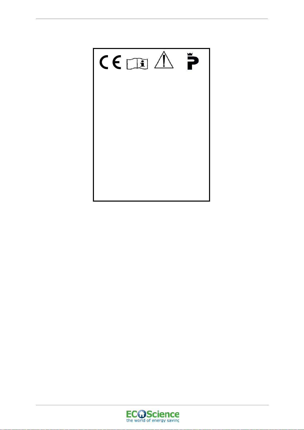
1.4 PRODUCT MARKING
ECOScience carries the CE mark (according to ‘Figure 1. CE mark’),
which means it is designed, manufactured and described in keeping with
EU requirements, for more information see ‘APPENDIX 1 - EC
DECLARATION OF CONFORMITY’.
Figure 1. CE mark
Top connected system tank, CS300
Edition: 01; Last updated: 2011-04-12
© ECOScience
3
ECOScience ENERGY CENTRE
Manufacturer Fueltech Sweden AB
Model 6500i
Product number E65000100x
Volume/Water 520 litre
PED 97/23 Article 3.3
Voltage 400V 3N~ 50Hz
Output 9 kW
Frequency 50 Hz
Operating pressure
1.5/0.9 Max/min bar
Design temp. 85ºC
P mark SC0607-10
Certifying body SP SITAC
Inspection body SP
Date assembled xx-xx-20xx
AO number 20xx-xxx
Individual number E65000100x
1.4.1 Identification plate
INSTALLATION AND USER MANUAL
Figure 2. Identification plate
1.4.2 EC declaration of conformity
See ‘APPENDIX 1 - EC DECLARATION OF CONFORMITY’.
4
Top connected system tank, CS300
© ECOScience
Edition: 01; Last updated: 2011-04-12

ECOScience ENERGY CENTRE
2 SAFETY INSTRUCTIONS
2.1 GENERAL HAZARDS
INSTALLATION AND USER MANUAL
DANGER: HIGH CENTRE OF GRAVITY!
This product has a high centre of gravity and
precautionary measures must be taken.
DANGER: WEAK FOUNDATION!
Make sure that the location intended to house the
product will bear its weight (for more information see
‘ASSEMBLING THE SUPPORT BASE AND
SYSTEM TANK’ on page 11).
DANGER: RISK OF ELECTRIC SHOCK!
Always switch off the power before any work on the
energy centre starts.
DANGER: RISK OF INJURY!
Never put safety at risk by removing covers that are
screwed in place or by disabling the safety
equipment.
2.1.1 Space required
For information on the space required see ‘ASSEMBLING THE
SUPPORT BASE AND SYSTEM TANK’ on page 11.
2.1.2 Risks involving spare parts
Only use original spare parts from the product supplier.
Top connected system tank, CS300
Edition: 01; Last updated: 2011-04-12
© ECOScience
5
ECOScience ENERGY CENTRE
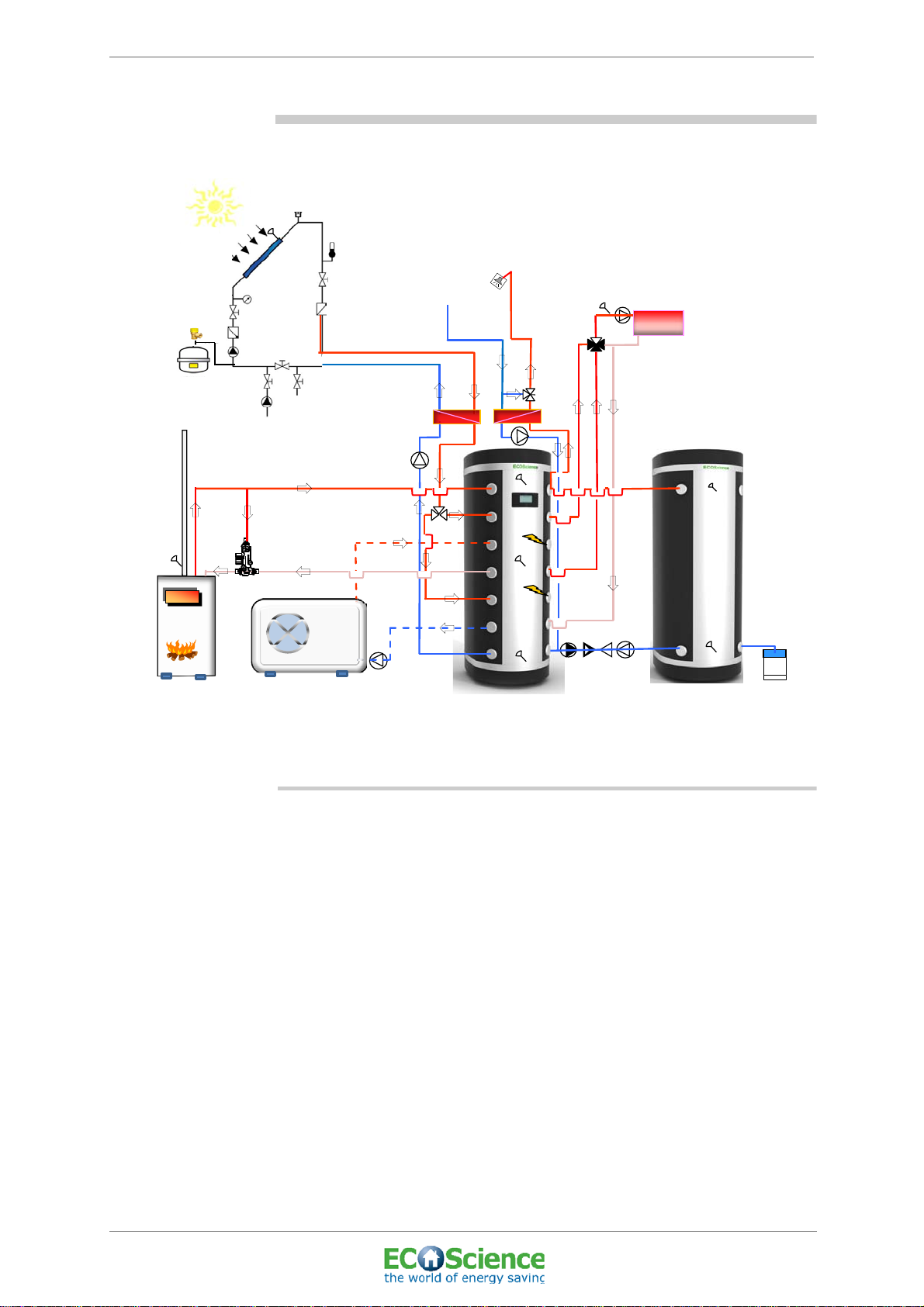
3 DESCRIPTION OF FUNCTIONS
INSTALLATION AND USER MANUAL
Figure 3. Schematic view of the system integration (with front connected piping)
3.1 GENERAL
The ECOScience Energy Centre is designed for domestic use and
provides a complete solution for heating and hot water.
The ECOScience Energy Centre enables you to harness and store
energy efficiently from many sources (e.g. solar energy, heat pump (air
or ground-sourced)/CHP/fuel cell or solid fuel/oil/gas/district heating).
The energy is then used to produce hot tap water and heat for radiators
or underfloor heating. It can also be used to heat a swimming pool.
The ECOScience Energy Centre comprises a system tank, an energy
central unit and a control system as standard. You can also choose
certain add-on modules e.g. solar heating system, solid fuel (waterjacketed pellet/wood stove, pellet/wood boiler), buffer tank, heat pump
and pool heating.
6
Top connected system tank, CS300
© ECOScience
Edition: 01; Last updated: 2011-04-12

ECOScience ENERGY CENTRE
3.1.1 System tank
The system tank is a water-filled tank that can be connected to external
energy sources. The heat energy for producing hot water can therefore
come from several different energy sources depending on the add-on
modules you have chosen. The standard system tank also has 2 built in
electric heaters (4.5 kW each) that can provide hot tap water and heating
separately (top heater and bottom heater). You can choose how much
power (1.5 kW, 3 kW or 4.5 kW) you want the electric heaters to
contribute using the control system.
There are three temperature sensors in the system tank, positioned at
the top, in the middle and at the bottom of the tank. The water at the top
of the tank is used for hot tap water, the water in the middle supplies the
radiators and the water at the bottom is used for underfloor heating or air
ventilation heating and for pool heating.
3.1.2 Energy central unit
The energy central unit, which can be integrated into the top of the
system tank, free-standing or wall-mounted, comprises a tap water
circuit, a solar load circuit and a heat circuit.
INSTALLATION AND USER MANUAL
The energy central unit features a safety valve that opens if the pressure
in the system exceeds 1.5 bar.
3.1.2.1 Tap water circuit
The tap water circuit manages the distribution of hot tap water for the
house’s existing pipe system and is equipped with a heat exchanger.
This allows tap water to be heated quickly and means that no water is left
standing in the system, thus eliminating any risk of Legionella growth.
The tap water circuit features a mixing valve to prevent scalding.
3.1.2.2 Solar loading circuit
The solar load circuit features a heat exchanger, a circulation pump and
a bivalent valve to distribute the hot water to the right level in the system
tank.
Top connected system tank, CS300
Edition: 01; Last updated: 2011-04-12
© ECOScience
7

ECOScience ENERGY CENTRE
3.1.2.3 Heat circuit
The heat circuit manages the distribution of hot water to the radiators or
underfloor heating. If you only have radiators or underfloor heating, the
control system coordinates the distribution of heat using a shunt valve
and a circulation pump, in conjunction with indoor and outdoor sensors.
The shunt valve mixes the hot supply water from the system tank with
the colder water from the return pipe so that the right temperature is
achieved for the water that feeds the radiators or underfloor heating. The
shunt valve is controlled using sensors that measure the outdoor
temperature, the indoor temperature and the supply pipe temperature.
If you have both radiators and underfloor heating, the control system can
only control the radiators. An external control unit is therefore required
for controlling underfloor heating. For further information contact your
Service Representative.
3.1.3 Control system
The control system ensures that at any given time, the most efficient
energy source is prioritised in order to produce the energy needed to
heat the water in the system tank.
INSTALLATION AND USER MANUAL
The control system is operated using a colour touchscreen located on
the front of the system tank.
General settings are already programmed in the control system when it
is delivered (see ‘ APPENDIX 4 - DEFAULT SETTINGS’), although each
installation will require customer-specific settings to optimise the
system. The installation engineer will do this during initial setup.
8
Top connected system tank, CS300
© ECOScience
Edition: 01; Last updated: 2011-04-12

ECOScience ENERGY CENTRE
4 ASSEMBLY AND INSTALLATION
4.1 BEFORE USE
Check that the packaging is intact and the product is not damaged
before using it. Check that none of the parts specified on the delivery
note are missing.
4.1.1 Safe disposal of packaging material
Sort the packaging by material according to local regulations.
PLEASE NOTE: PACKAGING CAN BE
RECYCLED!
In the development of ECOScience products and the
choice of materials used, much attention has been paid
to environmental considerations. Packaging can be
sorted into waste types for disposal and recycled.
ECOScience packaging material is therefore fully
recyclable.
INSTALLATION AND USER MANUAL
Top connected system tank, CS300
Edition: 01; Last updated: 2011-04-12
© ECOScience
9

ECOScience ENERGY CENTRE
4.2 GENERAL
PLEASE NOTE: EQUIPMENT!
ECOScience recommends the use of vacuum bleeding
and top-up devices (Flamco ENA or equivalent for
example) when setting up the product and system.
This will ensure that the system water is correct,
creating the right conditions for optimum energy
exchange.
If bleeding and top-up equipment is not used,
ECOScience shall not be liable under warranty.
PLEASE NOTE: INSTALLATION!
For flow chart see ‘APPENDIX 2 - FLOW CHART’.
INSTALLATION AND USER MANUAL
PLEASE NOTE: INSTALLATION!
Installation must be carried out in accordance with the
national standards and laws for heating and hot water
installations.
DANGER: RISK OF ELECTRIC SHOCK!
Always switch off the power before starting any work
on the energy centre. Electrical installations must
always be performed by a qualified electrician.
CAUTION: RISK OF MALFUNCTION!
Air bleeds from the system during initial setup.
10
Top connected system tank, CS300
© ECOScience
Edition: 01; Last updated: 2011-04-12

ECOScience ENERGY CENTRE
4.3 ASSEMBLING THE SUPPORT BASE AND SYSTEM TANK
4.3.1 Instructions
1. Ensure that the space intended to house the product is large
enough and that the floor is capable of bearing its weight. A clear
height of approximately 300 mm above the system tank is
recommended in order to facilitate the installation and adjustments.
For dimensions see ‘10 TECHNICAL DATA’ on page 51.
PLEASE NOTE: SPACE FOR
INSTALLATION!
There must be a floor drain where the system tank and
buffer tank are housed.
2. Remove the product from the packaging and carefully check that no
damage has occurred during transport/handling.
3. Lift out the support base and check that all 6 adjustable feet (1 of
which is spare) have been included.
4. Attach the feet to the support base.
5. Place the support base where the tank is to be installed.
6. Check that the support base sits flat using a spirit level as shown in
according to ‘Figure 4. Spirit level check’.
INSTALLATION AND USER MANUAL
Figure 4. Spirit level check
7. Lift the product off the pallet and place it over the support base.
8. Check that the support base is positioned directly under the tank.
9. Check that the product is not obstructed by any surrounding
equipment/structures.
10. Check again that the product sits flat using a spirit level, adjust the
feet if necessary.
CAUTION: RISK OF INSTABILITY!
Check that the product sits flat after it has been filled
to ensure its stability.
Top connected system tank, CS300
Edition: 01; Last updated: 2011-04-12
© ECOScience
11

ECOScience ENERGY CENTRE
4.4 CONNECTING THE PIPES
4.4.1 Please note
• All existing or new systems must be flushed clean before any pipe
fittings are connected permanently.
• The system tank must be connected to a closed expansion vessel.
A manometer that indicates the system pressure must be mounted
in the connection to the expansion vessel (see ‘ APPENDIX 2 FLOW CHART’). (The manometer and expansion vessel are
provided by the installation engineer.)
• The system pressure must not fall below 0.9 bar.
• ECOScience recommends stainless steel or PEX pipes. If these are
not available, copper pipes should be used.
INSTALLATION AND USER MANUAL
CAUTION! CUTTING PIPES!
In order to avoid any metal filings that may clog filters
and connections and lead to corrosion in the system,
pipes must only be cut with pipe cutters. Circular
cutting saws or hacksaws must not be used.
• All connection fittings to the system are ¾”.
4.4.2 Instructions
1. Connect pipes as shown in the pipe connection diagrams.
2. Fit an existing or new circulation pump to the radiator circuit supply
pipe (see ‘ APPENDIX 2 - FLOW CHART’ and see ‘ APPENDIX 3 WIRING DIAGRAM AND TEMPERATURE SENSORS’).
3. Connect a hose between the safety valve and floor drain (”4.4.3
Pipe connections” No. 7).
12
Top connected system tank, CS300
© ECOScience
Edition: 01; Last updated: 2011-04-12
ECOScience ENERGY CENTRE
7
17
8
4
15
18
5
14
16
1
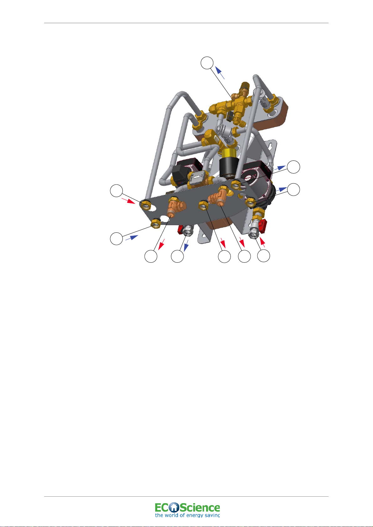
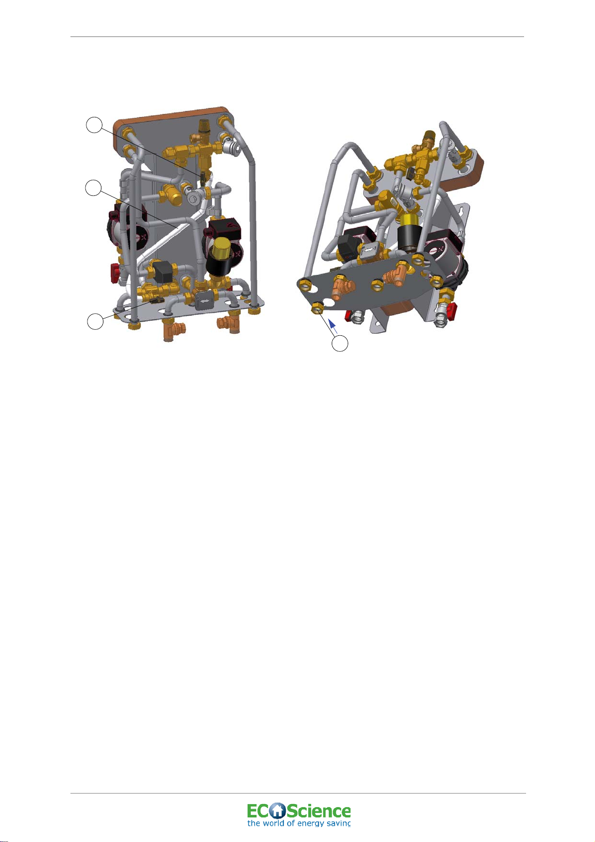
4.4.3 Pipe connections
INSTALLATION AND USER MANUAL
Figure 5. Energy Central Unit pipe connections
Top connected system tank, CS300
Edition: 01; Last updated: 2011-04-12
© ECOScience
13

ECOScience ENERGY CENTRE
13
19
23
12
*
**
9
6
9
10
18
17
14
15
19 9
11
6
13
16
12
B
22
6
21
20
A
C
VIEW FROM ABOVE
A: Bleeder valve
B: Reserve
C: Temperature sensors,
overheat protection
Connected when delivered
Please note! Connections 6 and 9
are top or front connections.
See ‘Figure 8. List of pipe connections’ on page 15.Pipe connections
for heat circuit:
INSTALLATION AND USER MANUAL
Figure 6. Pipe connections for top connected heat circuit
* Connected when delivered.
See ‘Figure 8. List of pipe connections’ on page 15.
Top connected system tank, CS300
© ECOScience
Edition: 01; Last updated: 2011-04-12
Figure 7. Pipe connections for top connected system tank
See ‘Figure 8. List of pipe connections’ on page 15.
14

ECOScience ENERGY CENTRE
No Connection
1 Return solar circuit I (to collector)
2 Supply to radiator circuit
3 Return from radiator circuit
4 Incoming cold tap water
5 Outgoing hot tap water
INSTALLATION AND USER MANUAL
6
7 Overflow pipe / Safety valve connection
8 Supply solar circuit I (from collector)
9 (i, wt) Buffer tank loading and unloading
9 (wf)
10 Return to heat pump / Return from pool
11
12 Supply to bivalent shunt high temp
13 Supply to bivalent shunt low temp
14 Supply > 61°C solar circuit II (from solar heat exchanger)
15 Supply < 61°C solar circuit II (from solar heat exchanger)
16 Supply from solid fuel / Supply to tap water heat exchanger
17 Return from tap water heat exchanger
18 Return solar circuit II (to solar heat exchanger)
Return to solid fuel without solar / Supply and return pump group
buffer tank / Expansion vessel
Supply to tap water heat exchanger / Buffer tank Loading and
unloading
Supply from heat pump low temp. / Return to solid fuel with solar /
Supply to pool
19 Return from bivalent shunt
20 Top electric heater
21 Bottom electric heater
22 Drain connection
23 (wf) Supply from heat pump high temp. / Return to solid fuel with solar
Figure 8. List of pipe connections
PLEASE NOTE: In order to facilitate installation, the connections at
equal level on the system tank are optional. This means that pipe
connections 16 and 9 , for example, may be switched.
Supply = from energy source, hot water
Return = to energy source, cold water
Top connected system tank, CS300
Edition: 01; Last updated: 2011-04-12
© ECOScience
15

ECOScience ENERGY CENTRE
12 5 4
3
4.5 ASSEMBLY OF TEMPERATURE SENSORS AND
OVERHEAT PROTECTION
INSTALLATION AND USER MANUAL
Figure 9. Tubes for temperature sensors and overheat protection see ‘Figure 7.
Pipe connections for top connected system tank’ on page 14 No. C
1. Tube for the temperature sensor at the top of the system tank.
system.
2. Tube for the overheat protection for the top electric heater in the
system tank.
3. Tube for the temperature sensor in the middle of the system tank.
4. Tube for the overheat protection for the bottom electric heater in the
system tank.
5. Tube for the temperature sensor at the bottom of the system tank.
4.5.1 Instructions
1. When replacing a temperature sensor or an overheat protection a
few drops of oil should be poured into the tube before the installing
of the temperature sensor or the overheat protection.
16
Top connected system tank, CS300
© ECOScience
Edition: 01; Last updated: 2011-04-12

ECOScience ENERGY CENTRE
4.6 ELECTRICAL INSTALLATION
4.6.1 Please note
• All installations and reconnections in the connection box must be
carried out by a qualified electrician.
• All wiring must be implemented in accordance with the applicable
rules.
• The equipment must be permanently connected to the correct
safety devices.
• High voltage power lines and low voltage cables must always be
kept separate to prevent interference problems (also outside the
product).
• The installation engineer is responsible for incoming switches.
4.6.2 Instructions
INSTALLATION AND USER MANUAL
1. Connect the incoming three-phase cable to an approved safety
switch.
PLEASE NOTE: WIRING DIAGRAM!
For wiring diagram see ‘APPENDIX 3 - WIRING
DIAGRAM AND TEMPERATURE SENSORS’ on
page 53.
DANGER: RISK OF ELECTRIC SHOCK!
Check that the switch is disconnected during wiring
(i.e. no current is running through the system).
PLEASE NOTE: CONNECTION
INFORMATION!
For connection information
see ‘10.3 TECHNICAL DATA, CONTROL SYSTEM’ on
page 52.
PLEASE NOTE: FOR SEPARATE
CIRCUITS!
If separate circuits are used for heating (via external
heat exchangers), the cable of the existing circulation
pump must be connected in parallel to the secondary
pump via an IP-rated box.
Top connected system tank, CS300
Edition: 01; Last updated: 2011-04-12
© ECOScience
17
ECOScience ENERGY CENTRE
4.7 FILLING THE SYSTEM WITH WATER
4.7.1 Please note
• All side systems must be flushed clean and be free of any
contamination. (Please note! Side systems must be flushed before
being connected to the system tank. If this has not been done, these
connections must be removed.)
INSTALLATION AND USER MANUAL
CAUTION: RISK OF MALFUNCTION!
The side system containing glycol or another
chemical mixture must be connected via the external
heat exchanger.
CAUTION: RISK OF MALFUNCTION!
If additional water is needed, the air bleeding process
must be performed again.
• The pH value of the water used in the system should be between
should be between 7 and 8.5, the ideal value being 8.
PLEASE NOTE: WATER QUALITY!
ECOScience recommends that a water sample be
taken to ensure the quality of the water. The
recommended pH value is between 7 and 8.5, 8 being
the ideal value.
4.7.2 Instructions
1. Always check the initial pressure in the expansion vessel using an
air pressure gauge before the system is filled.
CAUTION!
If the pressure in the expansion vessel is too low, it
must not be filled with regular air. Follow the
manufacturer’s instructions.
Height (m)
(between expansion
vessel and uppermost
point of system)
Initial pressure (bar)
in expansion vessel
(before filling)
System pressure (bar)
18
0-7 0.9 1.1
81.01.2
91.11.3
10 1.2 1.3
11 1. 3 1.3
• To ensure tap water is produced as intended, the system pressure
must never fall below 0.9 bar.
Top connected system tank, CS300
© ECOScience
Edition: 01; Last updated: 2011-04-12

ECOScience ENERGY CENTRE
PLEASE NOTE: SYSTEM PRESSURE!
The system pressure must never fall below 0.9 bar.
2. Check that the shut-off valves are open (”4.7.3 Connections and
shut-off valves” (No. 1 and 3)).
PLEASE NOTE: EQUIPMENT!
ECOScience recommends the use of vacuum
bleeding and top-up equipment (Flamco ENA or
equivalent for example) when the product and
system are being filled.
This will ensure that the system water is correct,
creating the right conditions for optimum energy
exchange.
If bleeding and top-up equipment is not used,
ECOScience shall not be liable under warranty.
INSTALLATION AND USER MANUAL
3. Make sure that the valve for bleeding air out of the system is open.
4. Connect the tap water via the tap water connection (No. 4) and fill
with water until water comes out of the bleeding valve.
5. Close the bleeding valve and continue to fill with water until the
desired system pressure is reached (min: 0.9 bar, max: 1.3 bar).
6. Check there are no leaks.
7. Close the shut-off valves (Nos. 1 and 3).
8. Remove hose (No. 2).
The system is now ready for commissioning (see ‘5 COMMISSIONING’)
Top connected system tank, CS300
Edition: 01; Last updated: 2011-04-12
© ECOScience
19
ECOScience ENERGY CENTRE
1
3
2
4
4.7.3 Connections and shut-off valves
INSTALLATION AND USER MANUAL
Figure 10. Filling the water system
1. Shut-off valve
2. Hose
3. Shut-off valve
4. Tap water connection
20
Top connected system tank, CS300
© ECOScience
Edition: 01; Last updated: 2011-04-12

ECOScience ENERGY CENTRE
4.8 EMPTYING THE SYSTEM TANK
4.8.1 Instructions
PLEASE NOTE: EMPTYING!
A hose connection is supplied for emptying the system
tank.
• Check that no current is running through the system.
• Remove the protection cover (, No. 22). see ‘Figure 7. Pipe
connections for top connected system tank’ on page 14
INSTALLATION AND USER MANUAL
DANGER: RISK OF ELECTRIC SHOCK!
Ensure no current is running through the system by
turning the main switch to OFF before emptying the
system tank.
• Open the drain valve by screwing the stopper off.
• Connect a hose to the hose connection supplied and ensure that
the other end of the hose is connected to a floor drain.
WARNING: RISK OF SCALDING!
Make sure than nothing comes into contact with the
water being emptied from the system tank – risk of
scalding.
• Fasten the hose connection to the drain valve. Note that the water
starts to be drawn off as soon as the connection is fastened on.
• Open the valve for bleeding air out of the system at the top of the
system tank , No. A) see ‘Figure 7. Pipe connections for top
connected system tank’ on page 14
Top connected system tank, CS300
Edition: 01; Last updated: 2011-04-12
© ECOScience
21

ECOScience ENERGY CENTRE
5 COMMISSIONING
Before operation, make sure you have read and understood section ”2
SAFETY INSTRUCTIONS” onwards.
RESPONSIBILITIES OF THE
INSTALLATION ENGINEER!
The installation engineer is responsible for walking
through the system with the end user.
5.1 PREPARATIONS BEFORE STARTING
Check that:
• The product is earthed.
• All parts are installed correctly and flushed clean.
INSTALLATION AND USER MANUAL
• There are no leaks in the system.
• All sensors are mounted and connected properly. The installation
engineer is responsible for ensuring that all sensors included with
delivery are installed in accordance with the flow chart. Outdoor
sensors must be positioned to be north-facing wherever possible.
Indoor sensors must be positioned 1.60 m above the floor, in the
centre of the house wherever possible and must not be exposed to
direct sunlight or located near a heat source.
5.2 START-UP
1. Turn on the main switch so that the display window lights up.
2. If necessary: Adjust the settings in the control system to optimise
the system.
3. Activate the heat-up sequence (see ‘6.3.3 Heat-up sequence’).
5.3 NORMAL STOP
1. Ensure no current is running through the system by turning the main
switch to OFF.
22
Top connected system tank, CS300
© ECOScience
Edition: 01; Last updated: 2011-04-12

ECOScience ENERGY CENTRE
6 CONTROL SYSTEM
6.1 START SCREEN (BASIC MODEL)
INSTALLATION AND USER MANUAL
PLEASE NOTE!
The ECOScience control system is pre-programmed in
the factory so that the product can be started directly to
provide heat and hot water. To restore these factory
settings press ‘Restore default values’ in the Setup
screen.
Figure 11. Basic start menu
• Press ‘System’ to continue.
PLEASE NOTE: ADD-ON MODULES!
This is the start screen for the basic system. Other
symbols will be displayed if add-on modules have been
installed.
Top connected system tank, CS300
Edition: 01; Last updated: 2011-04-12
© ECOScience
23

ECOScience ENERGY CENTRE
see 6.9
see 6.11
see 6.12
see 6.10
see 6.3
see 6.4
see 6.5
see 6.6
see 6.7
see 6.8
6.2 SYSTEM
All submenus for the system can be accessed from this menu. The
submenus for general settings are displayed on the left. The submenus
for setting the different modules are displayed on the right (the grey
buttons indicate add-ons that have not been chosen).
PLEASE NOTE: ADD-ON MODULES!
Grey text indicates an add-on module, requiring a
module key. To access extra add-ons please contact
your Service Representative.
INSTALLATION AND USER MANUAL
Figure 12. System menu
• Press the required button to continue.
• To return to the previous menu, press ‘Back’.
24
Top connected system tank, CS300
© ECOScience
Edition: 01; Last updated: 2011-04-12
ECOScience ENERGY CENTRE
see 6.3.1
see 6.3.2
see 6.3.4
see 6.3.5
see 6.3.3
see 6.3.6
see 6.3.7
see 6.3.8
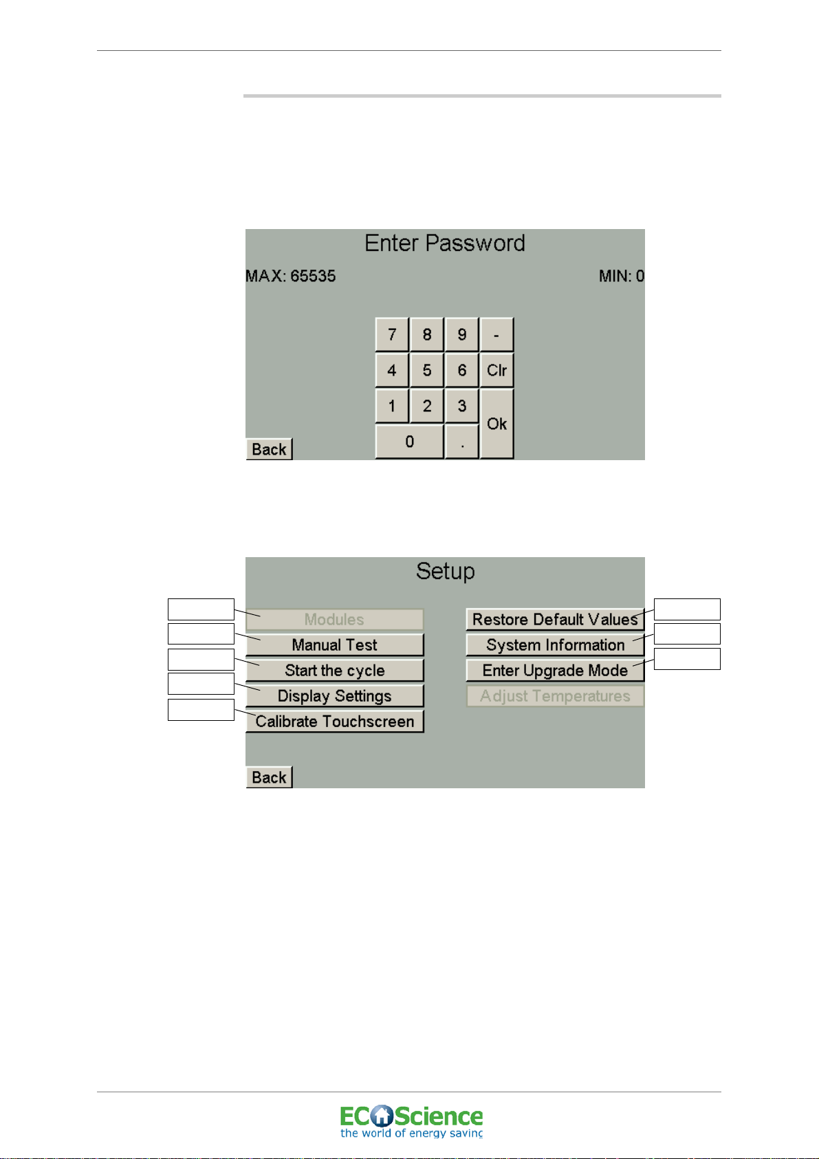
6.3 SETUP
To access the Setup menu, you must first enter a password in the code
menu.
The installation engineer also uses this menu to enter a code (known as
a ‘module key’) if add-on modules are chosen.
INSTALLATION AND USER MANUAL
Figure 13. Setup code menu
• Press the grey password box and enter the code 55. Then press OK
to continue.
Figure 14. Setup menu
• Press the required button to continue.
• To return to the previous menu, press ‘Back’.
Edition: 01; Last updated: 2011-04-12
6.3.1 Modules
This menu is used by the installation engineer if add-on modules have
been chosen. A code is required to access this menu. Contact your
installation engineer for more information.
Top connected system tank, CS300
© ECOScience
25
ECOScience ENERGY CENTRE
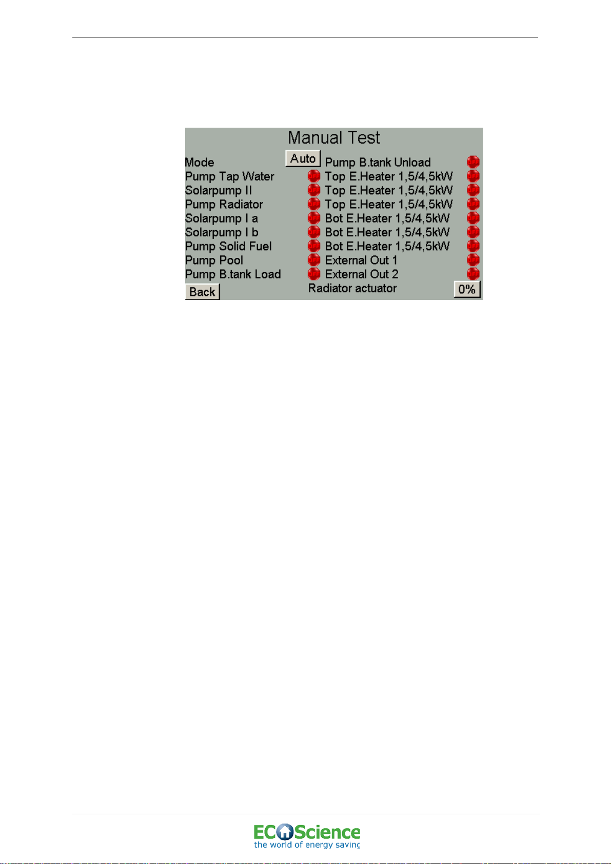
6.3.2 Manual operation
Here you can switch between automatic and manual operation of the
system.
Figure 15. Menu 1 ‘Manual operation’
INSTALLATION AND USER MANUAL
• To run the system manually, press ‘Auto’ so that the mode changes
to ‘Man’. (If the system is being operated manually, this is also
indicated on the start screen by ‘Manual operation’ flashing on the
screen.)
• To start or stop each function, press the lamp symbol (green=start,
red=stop).
• External Out 1 and External Out 2 control any external heat sources
that have been connected to the system (e.g. air-sourced heat
pump, pellet stove etc.).
• To specify how far the actuator must open, i.e. the amount of water
from the system tank that is to be distributed to the radiators/
underfloor heating, press the grey box marked ‘Radiator actuator’
and enter how far the actuator should open (enter value from 0 to
100%).
• To return to automatic operation, press ‘Man’ so that the mode
changes to ‘Auto’.
• To return to the previous menu, press ‘Back’.
26
Top connected system tank, CS300
© ECOScience
Edition: 01; Last updated: 2011-04-12
ECOScience ENERGY CENTRE
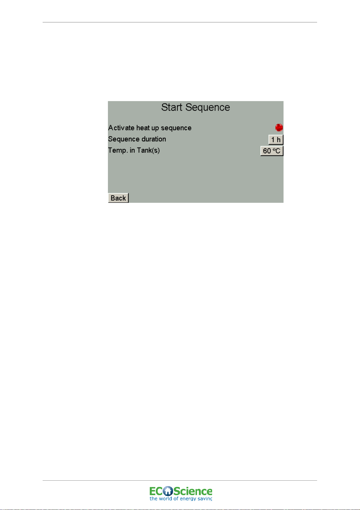
6.3.3 Heat-up sequence
When the system has been filled with water during installation and
servicing, the water should be heated up to a certain temperature for a
certain duration so as to ensure as little air in the system as possible.
During the heat-up sequence, air bleeds from the system via the bleeder
valve.
INSTALLATION AND USER MANUAL
Figure 16. ‘Start Sequence’ menu
• Set the desired duration by entering the number of hours that the
heat-up sequence should last (recommended duration: 2 hours).
• Specify the target temperature for the water by entering the desired
temp. in tank/tanks (recommended temp.: 80°C).
• To activate the heat-up sequence, press the lamp symbol so that it
turns green.
• To return to the previous menu, press ‘Back’.
Top connected system tank, CS300
Edition: 01; Last updated: 2011-04-12
© ECOScience
27

ECOScience ENERGY CENTRE
6.3.4 Display settings
Here you can program different settings for the display.
Figure 17. ‘Display settings’ menu
• Press the box for ‘Time before returned to startscreen’ and enter the
desired value.
INSTALLATION AND USER MANUAL
• Press the box for ‘Time before backlight is turned off’ and enter the
desired value.
6.3.5 Calibrating the touchscreen
• Press the cross in the top left-hand corner.
• Press the cross in the bottom right-hand corner.
• The new settings are now stored.
28
Top connected system tank, CS300
© ECOScience
Edition: 01; Last updated: 2011-04-12

ECOScience ENERGY CENTRE
6.3.6 Restore default values
Here you can restore the system to its default values.
Figure 18. ‘Restore Default Values’ menu
• Press ‘Yes’ to restore default values.
• Press ‘No’ to retain your own settings.
INSTALLATION AND USER MANUAL
PLEASE NOTE: DEFAULT VALUES!
See ‘APPENDIX 4 - DEFAULT SETTINGS’ for more
information.
6.3.7 System information
Information about the system is shown here.
Figure 19. ‘System Information’ menu
• To return to the previous menu, press ‘Back’.
6.3.8 Activating DFU mode
Activate DFU mode during upgrades.
Top connected system tank, CS300
Edition: 01; Last updated: 2011-04-12
© ECOScience
29

ECOScience ENERGY CENTRE
6.3.9 Calibrating the temperature sensors
The temperature sensors can be calibrated here against the actual
temperature. The installation engineer will measure the temperatures for
checking purposes during installation. In the event of any deviations, the
sensor in question should be adjusted (i.e. calibrated).
INSTALLATION AND USER MANUAL
Figure 20. Menu 1 'Temperature adjustments control circuit board'
Figure 21. Menu 2 'Temperature adjustments control circuit board'
30
Figure 22. Menu 1 'Temperature adjustments I/O circuit board'
Top connected system tank, CS300
© ECOScience
Edition: 01; Last updated: 2011-04-12

ECOScience ENERGY CENTRE
Figure 23. Menu 2 'Temperature adjustments I/O circuit board'
• "To calibrate the sensor in question press '-' or '+' until the actual
temperature is shown.
INSTALLATION AND USER MANUAL
• "To go to the next menu, press 'Next'.
• "To return to the previous menu, press 'Back'.
Top connected system tank, CS300
Edition: 01; Last updated: 2011-04-12
© ECOScience
31

ECOScience ENERGY CENTRE
6.4 DATE/TIME
The date and time are set here.
Figure 24. ‘Date/Time’ menu
INSTALLATION AND USER MANUAL
• Press the required box and enter the correct date and time.
• To return to the previous menu, press ‘Back’.
6.5 STATUS TEMP.
The current values indicated by the integrated temperature sensors are
shown here.
32
Figure 25. ‘Status Temp.’ menu
• Press ‘Next’ to see more values.
• To return to the previous menu, press ‘Back’.
• N/A may indicate the sensor is broken or is not connected, i.e. the
module is missing.
Top connected system tank, CS300
© ECOScience
Edition: 01; Last updated: 2011-04-12

ECOScience ENERGY CENTRE
6.6 STATUS I/O
The status of the system’s various units is shown here. The light symbols
indicate which units are active at the moment (green = active) (”6.6.1
Explanation of ‘Status I/O’ menu”).
INSTALLATION AND USER MANUAL
Figure 26. Menu 1 ‘Status I/O’
• Press ‘Next’ to see more units.
• To return to the previous menu, press ‘Back’.
Figure 27. Menu 2 ‘Status I/O’
• To return to the previous menu, press ‘Back’.
Top connected system tank, CS300
Edition: 01; Last updated: 2011-04-12
© ECOScience
33

ECOScience ENERGY CENTRE
6.6.1 Explanation of ‘Status I/O’ menu
INSTALLATION AND USER MANUAL
Pump Tap Water (tap water circuit)
Solar pump II -
Pump Radiator (heat circuit)
Solar pump I a 1 (single solar circuit)
Solar pump I b 2 (double solar circuit)
Pump Solid Fuel -
Lamp indicator Green ON
The circulation pump between the
system tank and the heat exchanger
for hot tap water (so-called secondary
side) is operating.
The circulation pump between the
system tank and the heat exchanger
for the solar circuit (so-called
secondary side) is operating.
The circulation pump between the
system tank and the radiators/
underfloor heating (i.e. heating in the
house) is operating.
The circulation pump between the
solar panels and the heat exchanger
for the solar load circuit (so-called
primary side) is operating.
The circulation pump between the
solar panels and the heat exchanger
for the solar load circuit (so-called
primary side) is operating.
The circulation pump between the
solid fuel source and the system tank
is operating.
Lamp indicator Red OFF
The circulation pump is not operating
(for example when no hot water is
being drawn).
The circulation pump is not operating
(see ‘Installation and user manual,
solar heating system’ for information)
The circulation pump is not operating
(for example when no extra heating is
needed in the house).
The circulation pump is not operating
(see ‘Installation and user manual,
solar heating system’ for information)
The circulation pump is not operating
(see ‘Installation and user manual,
solar heating system’ for information)
The circulation pump is not operating
(see ‘Installation and user manual,
solid fuel’ for information)
The circulation pump between the pool
Pump Pool -
Pump B.tank Load -
Pump B.tank Unload -
Top Electric Heater
1.5/4.5kW
Bottom. Electric Heater
1.5/4.5kW
External Out 1 - External heat source has started. External heat source has stopped.
External Out 2 - External heat source has started. External heat source has stopped.
External In 1 - Option to connect external control unit. External control unit is off.
exchanger and the system tank is
operating.
The circulation pump between the
system tank and the buffer tank is
operating.
The circulation pump between the
buffer tank and the system tank is
operating.
The electric heater at the top of the
system tank is on and producing
1.5 kW. Each lamp on means that the
electric heater is producing 1.5 kW
(2 lamps = 3 kW, 3 lamps = 4.5 kW).
The electric heater at the bottom of the
system tank is on and producing
1.5 kW. Each lamp on means that the
electric heater is producing 1.5 kW
(2 lamps = 3 kW, 3 lamps = 4.5 kW).
The circulation pump is not operating
(see ‘Installation and user manual,
pool’ for information)
The circulation pump is not operating
(see ‘Installation and user manual,
buffer tank’ for information)
The circulation pump is not operating
(see ‘Installation and user manual,
buffer tank’ for information)
The electric heater is not on.
The electric heater is not on.
External In 2 - Option to connect external control unit. External control unit is off.
Tap water flows and the switch starts
Flow Switch
the circulation pump for tap water heat
exchanger.
No tap water flows.
Top connected system tank, CS300
34
© ECOScience
Edition: 01; Last updated: 2011-04-12

ECOScience ENERGY CENTRE
INSTALLATION AND USER MANUAL
Lamp indicator Green ON
Phase L1 Incoming phase is OK, normal.
Phase L2 Incoming phase is OK, normal.
Bottom overheat
protection Ok
To p ov erheat protection
Ok
Radiator Actuator
overheat protection for the bottom
electric heater in the system tank has
not been triggered.
overheat protection for the top electric
heater in the system tank has not been
triggered.
Indicates how far the actuator is to open, determining the amount of water from
the system tank that is to be distributed to the radiators/underfloor heating.
Lamp indicator Red OFF
Phase missing (see ‘9.1 COMMON
FAULTS AND SOLUTIONS’)
Phase missing (see ‘9.1 COMMON
FAULTS AND SOLUTIONS’)
overheat protection for the bottom
electric heater in the system tank has
been triggered.
(see ‘9.3.1 Resetting overheat
protection for electric heaters’)
overheat protection for the top electric
heater in the system tank has been
triggered.
(see ‘9.3.1 Resetting overheat
protection for electric heaters’)
6.7 LANGUAGE
The language to be used in the display is selected here.
Figure 28. ‘Language’ menu
• Press the required flag to change the language.
• To return to the previous menu, press ‘Back’.
Top connected system tank, CS300
Edition: 01; Last updated: 2011-04-12
© ECOScience
35
ECOScience ENERGY CENTRE
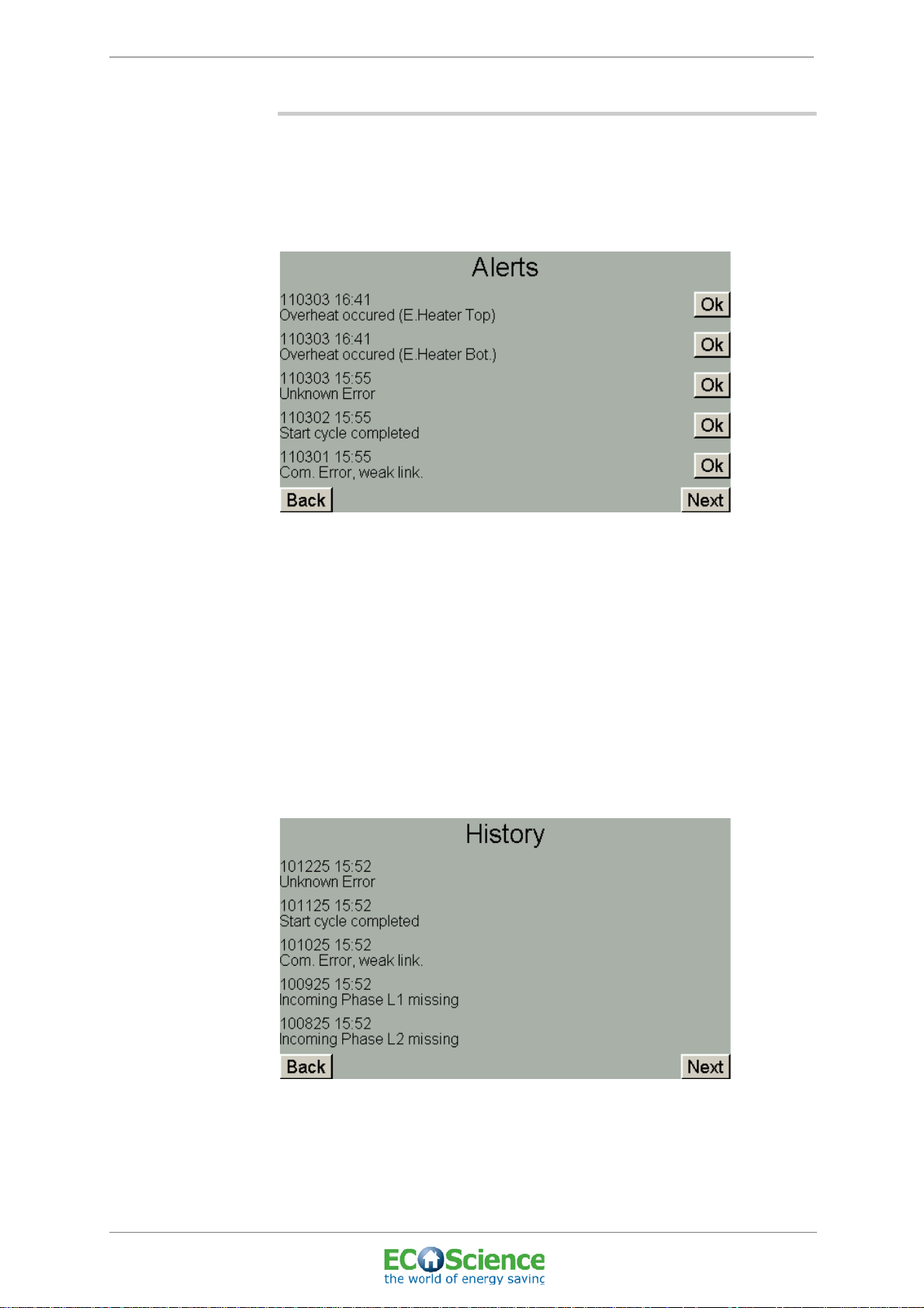
6.8 ALERTS/HISTORY
The various alerts that the system has generated but that have not yet
been acknowledged are shown here, together with the date and time the
alert was triggered. For more information see ‘9.3 ALERTS AND
SOLUTIONS’).
INSTALLATION AND USER MANUAL
Figure 29. ‘Alerts’ menu
• To acknowledge an alert, press ‘Ok’. Please note that some alert
triggers may require mechanical resetting so as to be
acknowledged, e.g. the overheat protection for the electric heater
(see ‘9.3.1 Resetting overheat protection for electric heaters’ on
page 50).
• To see more alerts press ‘Next’.
• To see the alert history press ‘Next’ again.
This menu shows the alerts previously generated by the system,
together with the date and time they occurred.
36
Figure 30. ‘History’ menu
• To see more alert history press ‘Next’.
• To return to the previous menu, press ‘Back’.
Top connected system tank, CS300
© ECOScience
Edition: 01; Last updated: 2011-04-12

ECOScience ENERGY CENTRE
6.9 HEATING
This menu can be used to activate the heat sources from which energy
is to be supplied to the system and to specify the temperatures at which
these are to be activated. The temperatures at which the pool is to be
heated are also set here, if you have chosen this add-on, together with
the power that you want the electric heaters to supply to the system. You
can also set the desired maximum temperature for the system tank.
INSTALLATION AND USER MANUAL
Figure 31. ‘Heating, System tank’ menu
• To set the start temperature for the heat source selected, press the
required box under ‘Start’ and enter the temperature at which the
heat source should start to supply heat to the system.
• To set the temperature at which the heat source should stop
producing heat for the system tank, press the required box under
‘Stop’ and enter the desired temperature.
• When the start and stop temperatures have been selected, activate
the heat source by pressing the red lamp symbol. This will turn
green, indicating that the heat source has been activated and will
produce heat for the system when the criteria (start and stop
temperatures) are met.
• To set the power that the electric heaters need to produce for
heating, press the box for the required electric heater and select
1.5kW, 3kW or 4.5kW.
• A tolerance of several degrees can be set to prevent the system
from switching off continuously when the temperature is around the
maximum temperature programmed for the system tank.
• To return to the previous menu, press ‘Back’.
Top connected system tank, CS300
Edition: 01; Last updated: 2011-04-12
© ECOScience
37

ECOScience ENERGY CENTRE
6.10 SOLAR CIRCUIT
The ECOScience Energy Centre has been designed to accommodate a
solar heating system. A solar loading circuit comprising a heat
exchanger and bivalent valve that distributes water at the right level in
the system tank is included in the basic model. See ‘ECOScience
Installation and user manual_Solar heating system’ for further details.
6.11 RADIATOR CIRCUIT
Here you can set the desired temperatures and times for the radiator
circuit and the desired indoor temperature. You can also set the pump to
stop when a certain outdoor temperature is reached. Stopping the pump
means that in order to save energy and prevent unnecessary heating,
the circulation pump to the radiators is turned off when the outdoor
temperature reaches a certain level.
INSTALLATION AND USER MANUAL
Figure 32. Menu 1 ‘Radiator Circuit’
• Press the required box and enter the desired value.
• To return to the previous menu, press ‘Back’.
• To go to the next menu, press ‘Next’.
38
Top connected system tank, CS300
© ECOScience
Edition: 01; Last updated: 2011-04-12

ECOScience ENERGY CENTRE
Figure 33. Menu 2 ‘Radiator Circuit
• Press ‘Temp. Curve’ to access the menu for setting the temperature
curve for the radiator circuit (”6.11.1 Radiator circuit temperature
curve”).
• Press ‘Settings’ to access the menu for temporarily reducing the
temperature for the radiator circuit (”6.11.2 Scheduled temperature
changes in radiator circuit”).
INSTALLATION AND USER MANUAL
• To return to the previous menu, press ‘Back’.
6.11.1 Radiator circuit temperature curve
The temperature curve is shown here. This is based on a curve which is
pre-programmed in the system.
Figure 34. ‘Radiator circuit temperature curve’ menu
• For a parallel shift in the curve upwards or downwards press ‘+1’ or
‘-1’.
• To set your own values for the curve press the grey boxes, enter the
desired value and then press OK.
• To return to the previous menu, press ‘Back’.
Top connected system tank, CS300
Edition: 01; Last updated: 2011-04-12
© ECOScience
39

ECOScience ENERGY CENTRE
6.1 1.2 Scheduled temperature changes in radiator circuit
Temporary reductions in temperature in the building (-1°C to -3°C
inclusive) can be programmed and activated in this menu for each day of
the week.
INSTALLATION AND USER MANUAL
Figure 35. ‘Scheduled temperature changes in radiator circuit’ menu
• To set the time that the temperature reduction is to begin, press the
time box (hr:min). Enter the desired time then click OK. Repeat this
procedure for the time when the temperature reduction is to end
and when the temperature is to return to its regular settings.
• To set the reduction in temperature (-1°C to -3°C inclusive) press
the required temperature box and enter the desired value.
• To set the day of the week on which the temperature reduction is to
start or end, press the box for the required day of the week. The box
will then appear crossed.
• To activate the temperature reduction, press the lamp symbol,
which then turns green.
• If a larger reduction in temperature is required or a temperature
reduction for a longer period, press ‘Next’ to access the holiday
reduction settings for radiators.
• To return to the previous menu, press ‘Back’.
• To go to the next menu, press ‘Next’.
40
Top connected system tank, CS300
© ECOScience
Edition: 01; Last updated: 2011-04-12

ECOScience ENERGY CENTRE
6.11.3 Radiator circuit holiday settings
This menu can be used to program and activate holiday settings for
radiators.
Figure 36. ‘Radiator circuit holiday settings’ menu
• Enter the start date when the reduction in temperature is to start or
the end date when the temperature is to return to its regular
settings.
INSTALLATION AND USER MANUAL
• Enter the desired temperature during holiday.
• To activate the holiday settings, press the lamp symbol, which then
turns green.
• To return to the previous menu, press ‘Back’.
Top connected system tank, CS300
Edition: 01; Last updated: 2011-04-12
© ECOScience
41
ECOScience ENERGY CENTRE
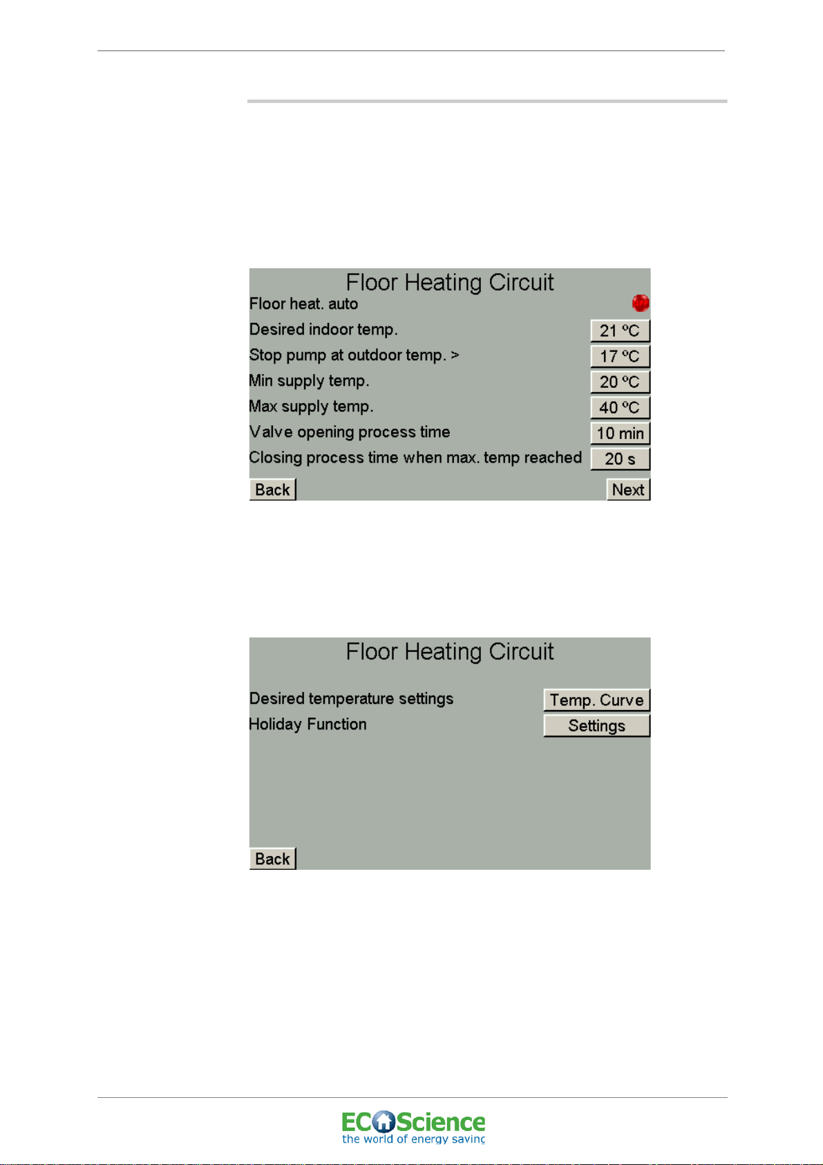
6.12 FLOOR HEATING CIRCUIT
Here you can set the temperature and times for underfloor heating and
the desired indoor temperature. You can also set the pump to stop when
a certain outdoor temperature is reached. Stopping the pump means
that the circulation pump for the floor heating is turned off when the
outdoor temperature reaches a certain level in order to save energy and
prevent unnecessary heating.
INSTALLATION AND USER MANUAL
Figure 37. Menu 1 ‘Floor Heating Circuit’
• Press the required box and enter the desired value.
• To return to the previous menu, press ‘Back’.
• To go to the next menu, press ‘Next’.
Figure 38. Menu 2 ‘Floor Heating Circuit’
• Press ‘Temp. curve’ to access the menu for setting the temperature
curve for the floor heating circuit (”6.12.1 Floor heating circuit
temperature curve”).
42
• Press ‘Settings’ to access the menu for temporarily reducing the
temperature for floor heating (”6.12.2 Scheduled temperature
changes in floor heating circuit”).
Top connected system tank, CS300
© ECOScience
Edition: 01; Last updated: 2011-04-12

ECOScience ENERGY CENTRE
6.12.1 Floor heating circuit temperature curve
The temperature curve is shown here. This is based on a curve which is
pre-programmed in the system.
Figure 39. ‘Floor heating circuit temperature curve’ menu
INSTALLATION AND USER MANUAL
• For a parallel shift in the curve upwards or downwards press ‘+1’ or
‘-1’.
• To set your own values for the curve press the grey boxes, enter the
desired value and then press OK.
• To return to the previous menu, press ‘Back’.
Top connected system tank, CS300
Edition: 01; Last updated: 2011-04-12
© ECOScience
43
ECOScience ENERGY CENTRE
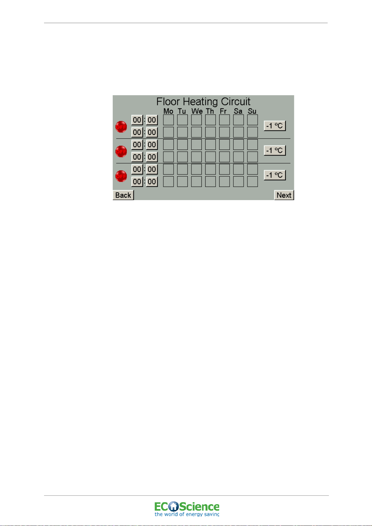
6.12.2 Scheduled temperature changes in floor heating circuit
Temporary reductions in the temperature in the building (-1°C to -3°C
inclusive) can be programmed and started/stopped in this menu for each
day of the week.
INSTALLATION AND USER MANUAL
Figure 40. ‘Scheduled temperature changes in floor heating circuit’ menu
• To set the time that the temperature reduction is to begin, press the
time box (hr:min). Enter the desired time then click OK. Repeat this
procedure for the time that the temperature reduction is to end and
the temperature is to return to its regular settings.
• To set the reduction in temperature (-1°C to -3°C inclusive) press
the required temperature box and enter the desired value.
• To set the day of the week on which the temperature reduction is to
start or end, press the box for the required day of the week. The box
will then appear checked.
• To activate the temperature reduction, press the lamp symbol,
which then turns green.
• If a larger reduction in temperature is required or a temperature
reduction for a longer period, press ‘Next’ to access the holiday
reduction settings for floor heating.
• To return to the previous menu, press ‘Back’.
• To go to the next menu, press ‘Next’.
44
Top connected system tank, CS300
© ECOScience
Edition: 01; Last updated: 2011-04-12
ECOScience ENERGY CENTRE
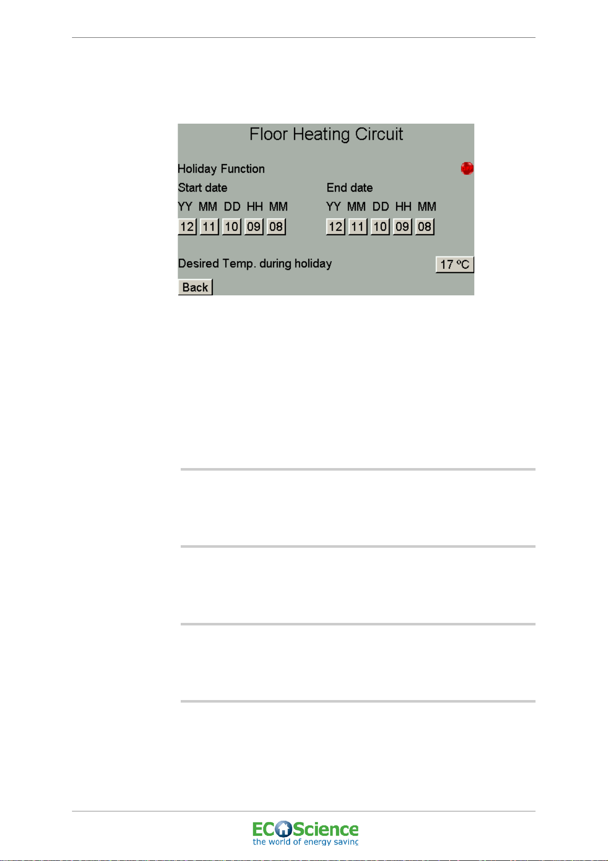
6.12.3 Floor heating circuit holiday settings
This menu can be used to program and activate holiday settings for floor
heating.
Figure 41. ‘Floor Heating Circuit Holiday Settings’ menu
INSTALLATION AND USER MANUAL
• Enter the start date when the reduction in temperature is to start or
the end date when the temperature is to return to its regular
settings.
• Enter the desired temp. during holiday.
• To activate the holiday settings, press the lamp symbol, which then
turns green.
• To return to the previous menu, press ‘Back’.
6.13 SOLID FUEL
Only when the add-on module is chosen. See ‘ECOScience Installation
and user manual – solid fuel’ for further details.
6.14 BUFFER TANK
Only when the add-on module is chosen. See ‘ECOScience Installation
and user manual - buffer tank’.
6.15 HEAT PUMP
Only when the add-on module is chosen. See ‘ECOScience Installation
and user manual - heat pump’.
6.16 POOL CONTROL
Only when the add-on module is chosen. See ‘ECOScience Installation
and user manual - pool’.
Top connected system tank, CS300
Edition: 01; Last updated: 2011-04-12
© ECOScience
45

ECOScience ENERGY CENTRE
7 MAINTENANCE
Before maintenance and cleaning, make sure you have read and
understood section ”2 SAFETY INSTRUCTIONS”.
7.1 MAINTENANCE AND FUNCTION CHECKS
7.1.1 Regular maintenance to be carried out at least once a year
• Check the safety valve by turning it anti-clockwise until it jumps out.
For the location of the safety valve see ‘4.4.3 Pipe connections’
(No. 7).
• Check the pressure in the system by reading the manometer
located in the connection to the expansion vessel.
INSTALLATION AND USER MANUAL
PLEASE NOTE: SYSTEM PRESSURE!
The system pressure must never fall below 0.9 bar.
7.2 CLEANING
Wipe the product regularly using a rag, warm water and a mild detergent.
CAUTION: RISK OF SURFACE DAMAGE!
Never use corrosive agents or agents that could
scratch the product!
46
Top connected system tank, CS300
© ECOScience
Edition: 01; Last updated: 2011-04-12

ECOScience ENERGY CENTRE
8 SERVICING AND REPAIRS
Servicing and repairs must be carried out by the installation engineer or
his/her representative. Before servicing and repairs, make sure you
have read and understood section ”2 SAFETY INSTRUCTIONS”.
INSTALLATION AND USER MANUAL
DANGER: RISK OF ELECTRIC SHOCK!
Turn the main switch to OFF before servicing!
The control panel must only be opened by qualified
professionals!
Top connected system tank, CS300
Edition: 01; Last updated: 2011-04-12
© ECOScience
47

ECOScience ENERGY CENTRE
INSTALLATION AND USER MANUAL
9 TROUBLESHOOTING
9.1 COMMON F AULTS AND SOLUTIONS
Description of problem Possible cause Solution
Noise from pump or radiators/floor
heating.
Fault in flow switch. This may be due to dirt in the flow
Low pressure in the system tank.
Manometer shows a pressure of
<0.9 bar.
No heat coming out to the radiators/
floor heating.
Phase L1 lamp illuminated in I/O
menu
Phase L2 lamp illuminated in I/O
menu
Often caused by air in the system. Bleed the air out of the system,
switch or if the switch is broken.
Possible leak or air has bled from
the system with no topping up.
Manual operation of shunt has been
activated via the control system or
actuator has been set to manual.
Error in radiator circuit circulation
pump.
Can be caused by air in the system.
Fault with incoming phase (L1). Contact a qualified electrician.
Fault with incoming phase (L2). Contact a qualified electrician.
including the pump.
Clean the flow switch.
Contact Service Representative.
Check that the system is not set
to manual operation (”6.3.2
Manual operation”)
Contact your Service
Representative if the circulation
pump has a fault.
Bleed the air out of the system,
including the pump.
Temperature value on screen shows
N/A.
The control system indicates hot
water being drawn but this is not
happening.
Temp. value on screen shows -40°C. Broken sensor or broken wire. Contact Service Representative
Sensor broken or not connected. Check sensor or contact Service
Representative.
Dirt may have collected in the flow
switch from incoming cold water
(municipal or from own well).
Clean the flow switch.
for change of temp. sensor.
48
Top connected system tank, CS300
© ECOScience
Edition: 01; Last updated: 2011-04-12

ECOScience ENERGY CENTRE
9.2 TABLE FOR RESISTANCE TEMPERATURE SENSOR PT 100
You can check that the temperature sensors are functioning properly by
using the table below and an instrument for measuring resistance.
Temp °C Resistance ohm DR/Dt ohm/°C
-20 92.160 0.393
-10 96.086 0.392
0 100.000 0.391
10 103.903 0.390
20 107.794 0.389
30 111.673 0.387
40 115.541 0.386
INSTALLATION AND USER MANUAL
50 119.397 0.385
60 123.242 0.384
70 127.075 0.383
80 130.897 0.382
90 134.707 0.380
100 138.506 0.379
Top connected system tank, CS300
Edition: 01; Last updated: 2011-04-12
© ECOScience
49

ECOScience ENERGY CENTRE
9.3 ALERTS AND SOLUTIONS
The control system has a monitoring function which triggers an alert if
something unexpected occurs. The alert is indicated by a red warning
triangle on the start screen. The triangle simply indicates that an alert
has occurred. To obtain more information on why the system has
generated an alert, go to the ‘Alerts’ menu (”6.8 ALERTS/HISTORY”).
Alert message Meaning and solution
INSTALLATION AND USER MANUAL
Overheat occurred (Electric Heater
Top/Bottom)
Communication Error Error in communication between
Start Seq. completed This is not an alert but notification
Incoming Phase L1/L2 missing Fault with incoming phase, contact
Heating circuit supply temp. not
reached.
Overheat protection for the electric
heater has been triggered (see ‘9.3.1
Resetting overheat protection for
electric heaters’ on page 50).
control circuit board and I/O circuit
board. Check cable.
that the start sequence is complete
(for more information see ‘6.3.3
Heat-up sequence’ on page 27).
qualified electrician.
Set value not reached. Possibly due
to air in the heating system. Check
the heating circuit circulation pump.
9.3.1 Resetting overheat protection for electric heaters
If the system has generated an alert indicating that the overheat
protection has been triggered for the top or bottom electric heater, it
must be reset. Please note that this protection should not normally be
triggered. However, if the protection has been triggered, the procedure
is as follows:
50
• Unscrew the protection plug on the cover of the connection box
which is located on the top of the tank and labelled ‘overheat
protection’.
• Reset the overheat protection by pressing down the white button
quite hard with a blunt object.
• Refasten the screw on the cover of the connection box.
• Acknowledge the alert in the ‘Alerts’ menu, see ‘6.8 ALERTS/
HISTORY’ on page 36.
PLEASE NOTE: OVERHEAT
PROTECTION!
If the overheat protection for the electric heaters is
activated often, ask your service representative to
troubleshoot the problem.
Top connected system tank, CS300
© ECOScience
Edition: 01; Last updated: 2011-04-12

ECOScience ENERGY CENTRE
INSTALLATION AND USER MANUAL
10 TECHNICAL DATA
10.1 TECHNICAL DATA, SYSTEM TANK
Model 6300wt 6500wt 8500wt 8750wt
Volume (litres) 312 520 520 780
Dimensions (LxWxH mm)
Tilt height (mm) 1660 2270 1960 2510
Overall height (mm) 1410 2070 1670 2270
Recommended room height
Required door width (mm) 700 700 800 800
Weight (kg) 47*) 64,5*) 60,5*) 77*)
Weight per support foot (kg) 71 117 116 171
(mm)
Figure 42. Technical data
*) Without energy central 21 kg
770x650x1410
1710 2370 1970 2570
770x650x2070 780x800x1670 780x800x2270
• The temperature in the system tank can be adjusted,
but max. 90°C.
• System pressure: min. 0.9 bar, max. 1.3 bar.
10.2 TECHNICAL DATA, ENERGY CENTRAL UNIT
• Opening pressure of safety valve is 1.5 bar.
• System pressure, on tank side, for tap water heat exchanger:
≥ 0.9 bar.
• System pressure, on cold water side, for tap water heat exchanger:
PN16
• Cleaning filters are fitted in the return pipe of the radiator circuit, and
on the supply pipe (secondary side) in front of heat exchangers for
hot tap water and for solar circuit.
Top connected system tank, CS300
Edition: 01; Last updated: 2011-04-12
© ECOScience
51

ECOScience ENERGY CENTRE
10.3 TECHNICAL DATA, CONTROL SYSTEM
Version ControlScience 300
Type PCB-based
Display 4.3” TFT touchscreen
Enclosure rating IP65
Type of enclosure Toughened PC
Max. usage temp 70°C.
Dimensions (LxWxH mm) 255x230x60
Weight (kg) 3.6
Connection Permanent installation
Voltage (V) 400
Fuse protection 16 A
INSTALLATION AND USER MANUAL
Number of phases 3
Figure 43. Control system CS300
52
Top connected system tank, CS300
© ECOScience
Edition: 01; Last updated: 2011-04-12

ECOScience ENERGY CENTRE
11 APPENDICES
APPENDIX 1 - EC DECLARATION OF CONFORMITY
APPENDIX 2 - FLOW CHART
APPENDIX 3 - WIRING DIAGRAM AND TEMPERATURE SENSORS
APPENDIX 4 - DEFAULT SETTINGS
APPENDIX 5 - LIST OF COMPONENTS
INSTALLATION AND USER MANUAL
Top connected system tank, CS300
Edition: 01; Last updated: 2011-04-12
© ECOScience
53

ECOScience ENERGY CENTRE
INSTALLATION AND USER MANUAL
54
Top connected system tank, CS300
© ECOScience
Edition: 01; Last updated: 2011-04-12

EG-försäkran om överensstämmelse
EC-déclaration de conformité
EC- declar at ion of con f ormity
EG-Konformitätserklärung
Fueltech Sweden AB
P.O Box 507
SE-372 25 RONNEBY
Tel: +46 (0)457-455 100
Fax: + 46 (0)457 455 125
försäkrar under eget ansvar att produkten
confirme sous sa responsabilité exclusive que le produit
declare under our sole responsibility that the product
erklären in alleiniger Verantwortung, dass das Produkt
Tank: xxxxxx
Typ nummer: xxxxxx
Produkfamilj: xxxxxx
som omfattas av denna försäkran är i överensstämmelse med följande standarder,
auquel cette déclaration se rapporte est en conformité avec les exigences des normes suivantes,
to which this declaration relates is in conformity with requirements of the following directives,
auf das sich diese Erklärung bezieht, konform ist mit den Anforderungen der Richtlinie,
EU-direktiv: 2006/95/EC Lågspänningsdirektivet
2004/108/EG EMC direktivet
2006/42/EG Maskindirektivet
Övrigt: PED 97/23 artikel 3.3 Hållfasthetstest
Kvalitetssystem: ISO 9001
ISO 14001
TS 1694 9
Överensstämmelsen är kontrollerad i enlighet med följande EN-standarder
La conformité a été contrôlée conformément aux normes EN,
The conformity was checked in accordance with the following EN-standards,
Die Konformität wurde überprüft nach den EN-Normen,
EN-14731:2006 EN-895 EN-9606-2:2005
EN-3834-2:2005 EN-15614-2:2005 EN-10042:2005
EN-1418 EN-10204:2005 EN-55014-1/-2
EN-61000-3 EN-60335-1 EN-50366:2002
Ronneby xxxx-xx-xx För sammanställning ansvarar
Håkan Björnsson
Quality Manager
Fueltech Sweden AB


Flow chart for heating and hot tap water


Wiring Diagram


Socket connections on circuit board
J12
J3
J2
Socket
no:
1 Buffer tank pump 2 (load buffer tank)
2 Buffer tank pump 1 (unload buffer tank)
3 Pool pump
pumps
Circulation
4 Pump for external heat source
5 Solar pump primary 2
6 Solar pump primary 1
7 Radiator pump
8 Solar pump (secondary side)
Circulation pumps
9 Tap water pump (secondary side)
10 Electric heater 2 bottom N
11 Electric heater 2 bottom B3
12 Electric heater 2 bottom B2
13 Electric heater 2 bottom B1
14 Electric heater 1 top N
External/Internal
Electric heaters
15 Electric heater 1 top T3
16 Electric heater 1 top T2
17 Electric heater 1 top T1
18 N
19 L3
J1
J4
20 L2
Incoming
power supply
21 L1
22 External control
23 External control
control
External
24 External control
Figure 44. Wiring diagram Control Science 300


Temperature Sensors
Control Circuit Board
Sensor Cable Text Function
“GT1” “1” System tank top
“GT2”
“GT3” “3” System tank bottom
“GT4” “4” Indoor temperature sensor
“GT5” “5” Outdoor temperature sensor
“GT6” “6” Radiators supply
“GT7” “7” Radiators return
“GT8” “8” Tap water
“GT9” “9” Secondary solar circuit
“GT10” “10” Primary I solar circuit
“GT11” “11” Primary II solar circuit
“GT12” “12”
“2”
System tank mid
Exhaust solid fuel
I/O Curcuit Board
PCB-Text Cable Text Function
“GT13” “1” Buffer tank top
“GT14”
“GT15” “3” Buffer tank bottom
“GT16” “4” Pool
“GT17” “5” Solid fuel supply
“GT18” “6” Solid fuel return
“GT19” “7” Spare
“GT20” “8” Spare
“GT21” “9” Spare
“GT22” “10” Spare
“GT23” “11” Spare
“GT24” “12” Spare
“2”
Spare


QUALITY CONTROL:
2010-07-02
REV 1.0
1.0
LTR
C
B
A
C
D
123456
DATE:
D
B
A
APPROVED:ECO NO:
REVISION RECORD
SCALE: SHEET:
1
OF
1
DRAWING NO:
TITLE:
COMPANY:
DATED:
RELEASED:
DATED:DRAWN:
CODE: REV:
B
Fueltech
Kent. O
Power supply
3x 400VAC TN-S
Max Fuse 16A
All incoming PE cables, ground, to the circuit board is to be connected
to the M4 screw – marked with PE on the circuit board.
All incoming PE cables, ground, to the circuit board is to be connected
to the M4 screw – marked with PE on the circuit board.
PE
J1
ELECTRIC HEATER_1_TOP_PE
J2
N
N
N
N
N
All incoming PE cables, ground, to the circuit board is to be connected
to the M4 screw – marked with PE on the circuit board.
J3
PE
PE
J4
J5
N
N
N
N
J12
J6
GT1
GT2
GT3
GT4
GT5
GT6
GT7
GT8
GT9
GT10
GT11
GT12
J8
J9
Incoming power supply
Electric heaters
External control
IN/OUT cables +24VDC Circulation pumps
Circulation pumpsCAN-busCAN-bus
PT100 Temperature sensors
Socket connections
on circuit board.
J1-1
J1-2
J1-3
J1-4
PE
J2-1
J2-2
J2-3
J2-4
J2-5
J2-6
J2-7
J2-8
PE PE
PE PE
J3-1
J3-2
J3-3
J3-4
J3-5
J3-6
J3-7
J3-8
J3-9
J3-10
J4-1
J4-2
J4-3
J4-4
J4-5
J4-6
J5-1
J5-2
J5-3
J5-4
J5-5
J5-6
J5-7
J5-8
J5-9
J5-10
J5-11
J5-13
J12-1
J12-2
J12-3
J12-4
J12-5
J12-6
J12-7
J12-8
J6-1
J6-2
J6-3
J6-4
J6-5
J6-6
J6-7
J6-8
J6-9
J6-10
J6-11
J6-12
J6-13
J6-14
J6-15
J6-16
J6-17
J6-18
J6-19
J6-20
J6-21
J6-22
J6-23
J6-24
J8-1
J8-2
J8-3
J8-4
J8-5
J8-6
J9-1
J9-2
J9-3
J9-4
J9-5
J9-6
L1
L2
L3
N
PE
ELECTRIC HEATER_1_TOP_T1
ELECTRIC HEATER_1_TOP_T2
ELECTRIC HEATER_1_TOP_T3
ELECTRIC HEATER_1_TOP_N
ELECTRIC HEATER_2_BOTTOM_B1
ELECTRIC HEATER_2_BOTTOM_B2
ELECTRIC HEATER_2_BOTTOM_B3
ELECTRIC HEATER_2_BOTTOM_N
TAP_WATER_PUMP
TAP_WATER_PUMP
SOLAR_ SEC._PUMP
SOLAR_ SEC._PUMP
RADIATOR_PUMP
RADIATOR_PUMP
SOLAR_ PRIM._1_PUMP
SOLAR_ PRIM._1_PUMP
SOLAR_ PRIM._2_PUMP
SOLAR_ PRIM._2_PUMP
EXT_1
EXT_1
EXT_1
EXT_2
EXT_2
EXT_2
+24V_SHUNT
GND_SHUNT
0-10V_SHUNT
FLOW_SWITCH
FLOW_SWITCH
THERM_CUT-OUT_HEATER_1_TOP
THERM_CUT-OUT_HEATER_1_TOP
THERM_CUT-OUT_HEATER_2_BOTTOM
THERM_CUT-OUT_HEATER_2_BOTTOM
EXT1_IN+
EXT1_IN-
EXT2_IN+
EXT2_IN-
EXT._HEATER_PUMP
EXT._HEATER_PUMP
POOL_PUMP
POOL_PUMP
BUFFER_TANK_PUMP_1
BUFFER_TANK_PUMP_1
BUFFER_TANK_PUMP_2
BUFFER_TANK_PUMP_2
System tank top
System tank mid
System tank bottom
Indoor temperature sensor
Outdoor temperature sensor
Radiators Supply
Radiators Return
Tap water
Secondary solar circuit
Primary I solar circuit
Primary II solar circuit
Smoke Solid Fuel
CANH
CANL
GND
+24VDC
J5-12
Smoke Solid Fuel
Primary II solar circuit
Primary I solar circuit
Secondary solar circuit
Tap water
Radiators Return
Radiators Supply
Outdoor temperature sensor
Indoor temperature sensor
System tank bottom
System tank mid
System tank top
CHECKED:
DATED:
DATED:
SIZE:
CANH
CANL
GND
+24VDC

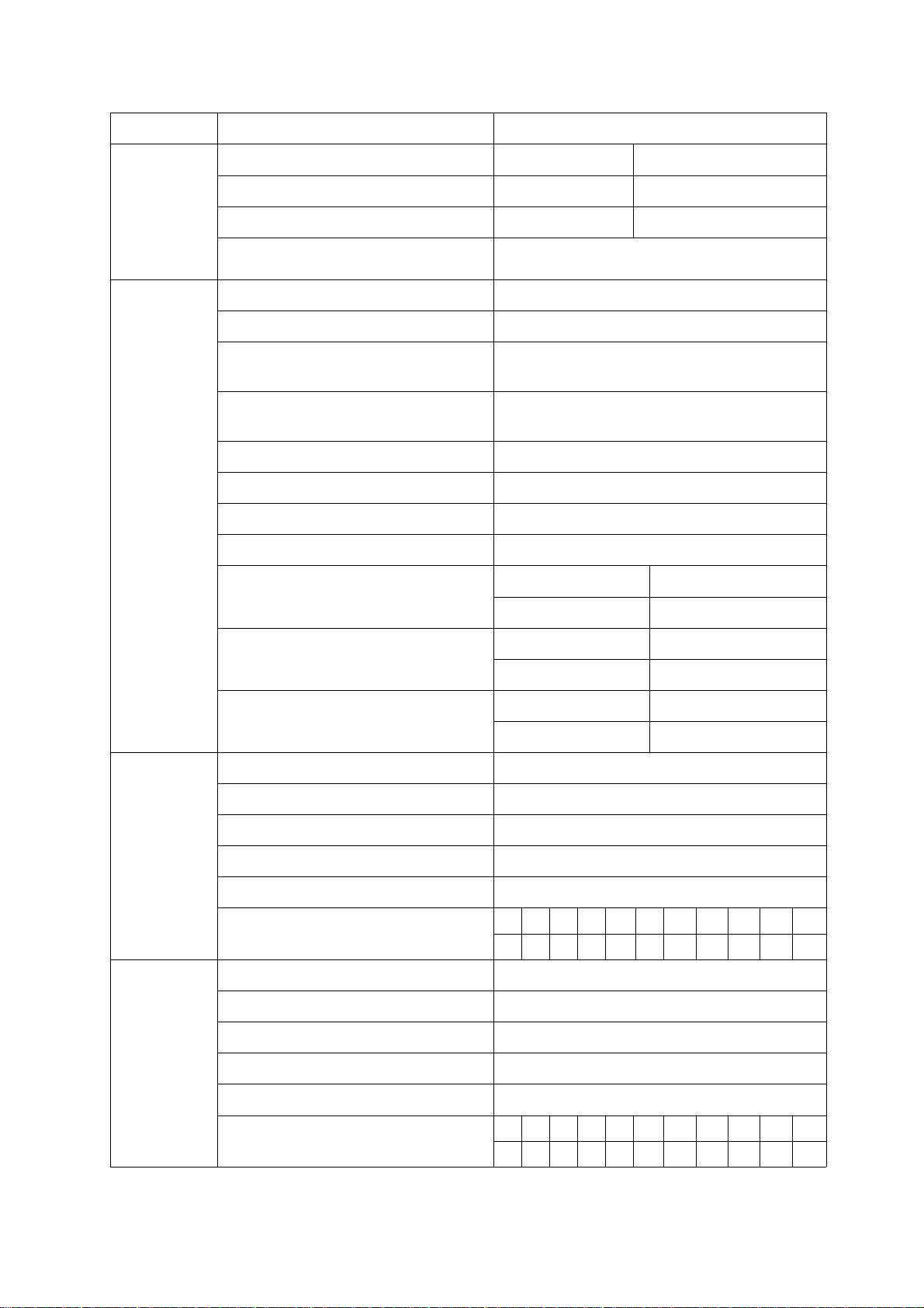
Default settings
Module Description Default settings (standard value)
Heating Solid fuel – middle of system tank Start at 50°C Stop at 52°C
Electric heater 1 – top of system tank Start at 58°C Stop at 72°C
Electric heater 2 – middle of system tank Start at 58°C Stop at 72°C
Max temperature in tank – top of system
tank
90°C
Solar circuit Secondary circuit start delay 30 seconds
Primary circuit tolerance 4°C
Temperature measuring interval,
2 minutes
secondary circuit
Temperature measuring duration,
30 seconds
secondary circuit
Secondary circuit tolerance 2°C
Primary circuit max. temperature 90°C
Primary circuit min. temperature -20°C
Cooling duration, primary circuit 60 seconds
Seasonal settings: February - April To: 9 am 9 Cut-off: 5°C
From: 5 pm 17 Duration: 60 minutes
May - July To: 2 am 2 Cut-off: 5°C
From: 10 pm 22 Duration: 60 minutes
Radiator
circuit
Floor heating
circuit
August - October To: 10 am 10 Cut-off: 5°C
From: 6 pm 18 Duration: 60 minutes
Desired indoor temperature 20°C
Pump stop at outdoor temperature above 18°C
Min. temperature in circuit 20°C
Max. temperature in circuit 65°C
Time for shunt to open 8 minutes
Radiator circuit temperature curve
18 23 28 33 38 43 46 48 50 53 54
20 15 10 5 0 -5 -10 -15 -20 -25 -30
Desired indoor temperature 20°C
Pump stop at outdoor temperature above 18°C
Min. temperature in circuit 20°C
Max. temperature in circuit 45°C
Time for shunt to open 8 minutes
Floor heating circuit temperature curve
20 22 24 26 28 30 32 34 36 38 40
20 15 10 5 0 -5 -10 -15 -20 -25 -30
Figure 45. Default settings

List of Components

Pos Qty
1
(Included in pos. 6)
1
2 Control Valve DN15 Samson 2432N Kvs 2,5 1
3 3-way valve Valve 6320A LK ACASO 1
4 Safety valve 1,5 Bar 1
5 Heat exchanger CB20-20H 1
6 Heat exchanger CB20IS-35H 1
7 Control valve TA Trim K 3/4" 2
8 Brass part Brass part 1 4
9 Strainer Brass part, angle 2
10 Shut off valve 3/4" In_Out 2
11 Strainer 3/4" Out, 90 degrees angle 1
12 Clamp Galvanized steel, 16-20mm 4
13 Frame Galvanized steel 1
14 Pipe Stainless steel, 18 mm 1
15 Pipe Stainless steel, 18 mm 1
16 Pipe Stainless steel, 18 mm 1
17 Pipe Stainless steel, 18 mm 1
18 Brass part Multi connection 1 1
19 Brass part Plug 3
20 Pipe Stainless steel, 18 mm 1
21 Pipe Stainless steel, 18 mm 1
22 Circular Pump UPS 15-40-130, turned 270 degrees 1
23 Brass part 3/4" x 22, 726619 LK-Armatur 7
24 Pipe Stainless steel, 18mm 1
25 Filling valve 90 degrees angle 2
26 Brass part Multi connection 2 1
27 Brass part Out G3/4" In G1/2" with O-ring sealing 1
28 Flow switch Henke-Sass 1
29 Pipe Stainless steel, 18mm 1
30 Non return valve DN15 1
31 Pipe Stainless steel, 18mm 1
33 Pipe Stainless steel, 18mm 1
34 Pipe Stainless steel, 18mm 1
35 Hose Nylon-hose 15 x 19 x 110 mm 1
36 Gasket 3/4" 22
38 Washer D24-40 mm (T=3 mm) 4
39 Brass part Nut ¾” low (T=6 mm) 4
40 Circular pump UPS 15-60-130, turned 90 grader 1

 Loading...