


SHENZHEN MOST ELECTRONICS CO., LTD.
Tel:(86) 755-26825180 Fax:(86) 755-86170310
Http:// www. szmost.com Email: szmost@szmost.com
Test Report
Product Name: PS3 WIRELESS GUITAR
FCC ID: SIWHP5195A
MODEL NO. : HP5195
Applicant:
E-CORE TECHNOLOGY(CHINA) CO., LTD.
3rd Building, Wei Dong Long Industry,
Shenzhen City, Guang Dong Province
He Ping East, Long Hua Town,
Date Received: 08/08/2007-08/10/2009
Date Tested: 08/10/2007
APPLICANT: E-CORE TECHNOLOGY(CHINA) CO., LTD.
FCC ID: SIWHP5195A
Cover Sheet
SHENZHEN MOST ELECTRONICS CO., LTD.
Tel:(86) 755-26825180 Fax:(86) 755-86170310
Http:// www. szmost.com Email: szmost@szmost.com
TABLE OF CONTENTS
APPLICANT: E-CORE TECHNOLOGY(CHINA) CO., LTD.
FCC ID: SIWHP5195A
TEST REPORT CONTAINING:
EXHIBIT INCLUDED:
PAGE 1...........TEST EQUIPMENT LIST
PAGE 2...........TEST PROCEDURE
PAGE 3-4.........RADIATION INTERFERENCE TEST DATA
PAGE 5-8.........OCCUPIED BANDWIDTH AND PLOTS
PAGE 1...........BLOCK DIAGRAM
PAGE 2...........SCHEMATIC
PAGE 3...........USERS MANUAL
PAGE 4...........LABEL SAMPLE
PAGE 5...........LABEL LOCATION
PAGE 6...........EXTERNAL PHOTOGRAPHS
PAGE 7...........INTERNAL PHOTOGRAPHS
PAGE 8...........OPERATIONAL DESCRIPTION
PAGE 9...........TEST SET UP PHOTOGRAPHS
APPLICANT: E-CORE TECHNOLOGY(CHINA) CO., LTD.
FCC ID: SIWHP5195A
TABLE OF CONTENTS
SHENZHEN MOST ELECTRONICS CO., LTD.
Tel:(86) 755-26825180 Fax:(86) 755-86170310
Http:// www. szmost.com Email: szmost@szmost.com
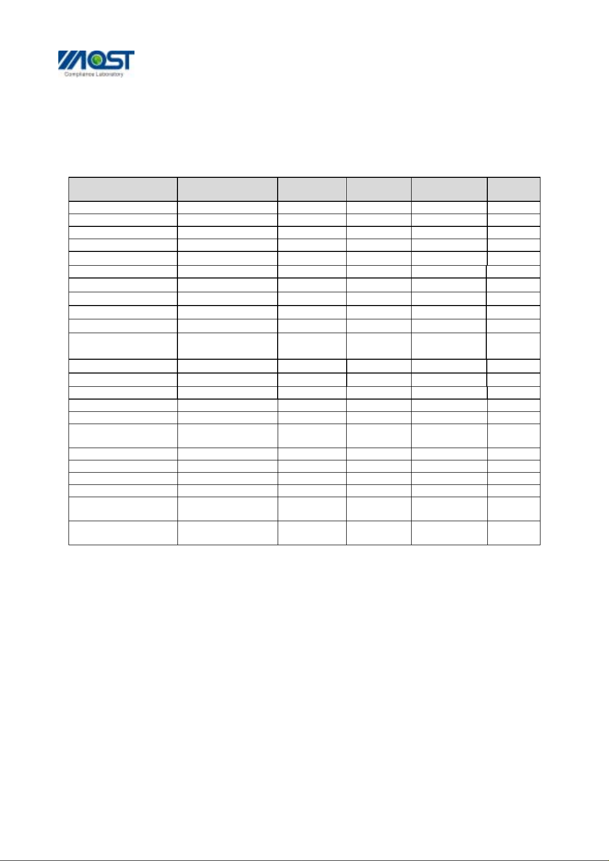
EMC Equipment List
Equipment Manufacturer Model No. Serial No. Last Cal. Cal.
Interval
EMI Test Receiver ROHDE&SCHWARZ ESCI 100492 Apr 06,2007 1 Year
LISN ROHDE&SCHWARZ ENV216 100093 Apr 06,2007 1Year
EMI Test Receiver ROHDE&SCHWARZ ESCI 101202 Apr 06,2007 1 Year
Spectrum Analyzer ANRITSU MS2651B 6200238316 Apr 06,2007 1 Year
50Ω Coaxial Switch
Bilog Antenna Sunol JB3 A121206 Apr 06,2007 1 Year
50Ω Coaxial Switch
Cable Resenberger N/A NO.1
Cable SCHWARZBECK N/A NO.2
Cable SCHWARZBECK N/A NO.3
Single Phase Power
Line Filter
AC Power Source
Test analyzer
ESD Tester Kikusui KES4021 LM003537 Apr 08,2007 1 Year
Signal Generator IFR 2032 203002/100 Apr 08,2007 1 Year
Amplifier A&R 150W1000 301584 NCR NCR
Dual Directional
Coupler
Power Head A&R PH2000 301193 Apr 06,2007 1 Year
Power Meter A&R PM2002 302799 Apr 06,2007 1 Year
Field Monitor A&R FM5004 300329 Apr 06,2007 1 Year
Field Probe A&R FP5000 300221 Apr 06,2007 1 Year
EMCPRO System
ANRITSU CORP MP59B 6200283933 Apr 06,2007 1 Year
ANRITSU CORP MP59B 6200283933 Apr 06,2007 1 Year
Apr 06,2007 1 Year
Apr 06,2007 1 Year
Apr 06,2007 1 Year
Kikusui LIN40MA-PC
R-L
Kikusui AC40MA LM003232 Apr 06,2007
Kikusui KHA1000 LM003720 Apr 06,2007
A&R DC6080 301508 Apr 06,2007 1 Year
EM Test UCS-500-M4 V0648102026 Apr 06,2007 1 Year
LM002352 Apr 06,2007
1Year
1Year
1Year
EMCPRO System
Remark:
Test Firm Name: Most Technology Service Co., Ltd.
Test Firm Address:
FCC Registered Test Site Number: 490827
APPLICANT: E-CORE TECHNOLOGY(CHINA) CO., LTD.
FCC ID: SIWHP5195A
EM Test UCS-500-M4 V0648102026 Apr 06,2007 1 Year
No. 5, 2nd Langshan Road, North District, Hi-tech Industrial
Park,Nanshan, Shenzhen, Guangdong, China
Page 1 of 8

SHENZHEN MOST ELECTRONICS CO., LTD.
Tel:(86) 755-26825180 Fax:(86) 755-86170310
Http:// www. szmost.com Email: szmost@szmost.com
TEST PROCEDURE
GENERAL: This report shall NOT be reproduced except in full without the written
approval of MOST TECHNOLOGY SERVICE CO., LTD. The EUT was transmitting a test signal
during the testing.
POWER LINE CONDUCTED INTERFERENCE: The test procedure used was ANSI Standard
C63.4-2003 using a 50uH LISN. Both Lines were observed. The bandwidth of the receiver
was 10kHz with an appropriate sweep speed. The ambient temperature of the EUT was
℃ with a humidity of 58%.
25
RADIATION INTERFERENCE: The test procedure used was ANSI Standard C63.4-2003 using
a ANRITSU spectrum analyzer with a pre-selector. The analyzer was calibrated in dB
above a micro volt at the output of the antenna. The resolution bandwidth was 100
kHz and the video bandwidth was 300 kHz up to 1 GHz and 1 MHz with a video BW of 3
MHz above 1 GHz. The ambient temperature of the EUT was 25
℃ with a humidity of 58%.
FORMULA OF CONVERSION FACTORS: The Field Strength at 3m was established by adding
the meter reading of the spectrum analyzer (which is set to read in units of dBuV)
to the antenna correction factor supplied by the antenna manufacturer. The antenna
correction factors are stated in terms of dB. The gain of the Pre-selector was
accounted for in the Spectrum Analyzer Meter Reading.
Example:
Freq (MHz) METER READING + ACF = FS
33 20 dBuV + 10.36 dB = 30.36 dBuV/m @ 3m
ANSI STANDARD C63.4-2003 10.1.7 MEASUREMENT PROCEDURES: The EUT was placed on a table
80 cm high and with dimensions of 1m by 1.5m. The EUT was placed in the center of
the table (1.5m side). The table used for radiated measurements is capable of
continuous rotation.
When an emission was found, the table was rotated to produce the maximum signal
strength. At this point, the antenna was raised and lowered from 1m to 4m. The antenna
was placed in both the horizontal and vertical planes.
The situation was similar for the conducted measurement except that the table did
not rotate. The EUT was setup as described in ANSI Standard C63.4-2003 10.1.7 with
the EUT 40 cm from the vertical ground wall.
APPLICANT: E-CORE TECHNOLOGY(CHINA) CO., LTD.
FCC ID: SIWHP5195A
Page 2 of 8

SHENZHEN MOST ELECTRONICS CO., LTD.
Tel:(86) 755-26825180 Fax:(86) 755-86170310
Http:// www. szmost.com Email: szmost@szmost.com
APPLICANT: E-CORE TECHNOLOGY(CHINA) CO., LTD.
FCC ID: SIWHP5195A
NAME OF TEST: RADIATION INTERFERENCE
RULES PART NUMBER: 15.249, 15.209
REQUIREMENTS:
FIELD STRENGTH of
Fundamental:
FIELD STRENGTH
of Harmonics
S15.209
902-928 MHZ
2.4-2.4835 GHz
94 dBuV/m @3m
54 dBuV/m @3m
30 -88 MHz 40 dBuV/m @3M
88 - 216 MHz 43.5
216 - 960 MHz 46
ABOVE 960 MHz 54dBuV/m
EMISSIONS RADIATED OUTSIDE OF THE SPECIFIED FREQUENCY BANDS, EXCEPT FOR HARMONICS,
SHALL BE ATTENUATED BY AT LEAST 50 dB BELOW THE LEVEL OF THE FUNDAMENTAL OR TO THE
GENERAL RADIATED EMISSION LIMITS IN 15.209, WHICHEVER IS THE LESSER ATTENUATION.
Frequency (MHz) Antenna Polarization Emission Level (dBuV/m) FCC 15 Subpart C Limit
(dBuV/m)
Low frequency(2410.00 MHz)
136.00 Vertical 32.10 43.5
231.00 Vertical 31.60 46.0
2410.00 Vertical 82.05 94.0
4820.00 Vertical 32.40 54.0
7230.10 Vertical 31.65 54.0
12050.20 Vertical 32.15 54.0
135.15 Horizontal 31.43 43.5
238.00 Horizontal 32.50 46.0
2410.00 Horizontal 83.50 94.0
4820.00 Horizontal 31.20 54.0
7230.10 Horizontal 32.30 54.0
12050.20 Horizontal 31.07 54.0
Middle frequency(2440.00 MHz)
135.30 Vertical 31.20 43.5
2440.00 Vertical 81.95 94.0
4880.10 Vertical 32.13 54.0
7320.20 Vertical 31.55 54.0
12200.30 Vertical 31.15 54.0
133.06 Horizontal 33.40 43.5
2440.00 Horizontal 82.15 94.0
4880.10 Horizontal 31.85 54.0
7320.20 Horizontal 32.00 54.0
12200.30 Horizontal 31.21 54.0
APPLICANT: E-CORE TECHNOLOGY(CHINA) CO., LTD.
FCC ID: SIWHP5195A
Page 3 of 8

SHENZHEN MOST ELECTRONICS CO., LTD.
Tel:(86) 755-26825180 Fax:(86) 755-86170310
Http:// www. szmost.com Email: szmost@szmost.com
APPLICANT: E-CORE TECHNOLOGY(CHINA) CO., LTD.
FCC ID: SIWHP5195A
NAME OF TEST: RADIATION INTERFERENCE
RULES PART NUMBER: 15.249, 15.209
REQUIREMENTS:
FIELD STRENGTH of
Fundamental:
FIELD STRENGTH
of Harmonics
S15.209
902-928 MHZ
2.4-2.4835 GHz
94 dBuV/m @3m
54 dBuV/m @3m
30 -88 MHz 40 dBuV/m @3M
88 - 216 MHz 43.5
216 - 960 MHz 46
ABOVE 960 MHz 54 dBuV/m
EMISSIONS RADIATED OUTSIDE OF THE SPECIFIED FREQUENCY BANDS, EXCEPT FOR HARMONICS,
SHALL BE ATTENUATED BY AT LEAST 50 dB BELOW THE LEVEL OF THE FUNDAMENTAL OR TO THE
GENERAL RADIATED EMISSION LIMITS IN 15.209, WHICHEVER IS THE LESSER ATTENUATION.
Continued:
Frequency (MHz) Antenna Polarization Emission Level (dBuV/m) FCC 15 Subpart C Limit
(dBuV/m)
High frequency(2470.0 MHz)
137.30 Vertical 30.50 43.5
2470.00 Vertical 82.15 94.0
4940.10 Vertical 31.56 54.0
7410.20 Vertical 32.30 54.0
12350.20 Vertical 31.45 54.0
136. 90 Horizontal 32.15 43.5
2470.00 Horizontal 81.86 94.0
4940.10 Horizontal 31.31 54.0
7410.20 Horizontal 32.10 54.0
12350.20 Horizontal 32.05 54.0
TEST PROCEDURE: ANSI Standard C63.4-2003 using a ANRITSU spectrum analyzer with a
pre-selector and an appropriate antenna. The resolution bandwidth of spectrum
analyzer was 100 kHz below 1 GHz and 1 MHz above 1 GHz. An appropriate sweep speed
was used. When an emission was found, the table was rotated to produce the maximum
signal strength. The antenna was placed in both the horizontal and vertical planes
and the worse case emissions were reported. The spectrum was searched to at least
the tenth (10) harmonic of the fundamental.
APPLICANT: E-CORE TECHNOLOGY(CHINA) CO., LTD.
FCC ID: SIWHP5195A
Page 4 of 8

SHENZHEN MOST ELECTRONICS CO., LTD.
Tel:(86) 755-26825180 Fax:(86) 755-86170310
Http:// www. szmost.com Email: szmost@szmost.com
APPLICANT: E-CORE TECHNOLOGY(CHINA) CO., LTD.
FCC ID: SIWHP5195A
NAME OF TEST: Occupied Bandwidth and Band Edge Compliance
RULES PART NUMBER: 15.249
REQUIREMENTS: The field strength of any emissions appearing outside the band
edges and up to 10 kHz above and below the band edges shall be
attenuated at least 50 dB below the level of the carrier or to
the general limits of 15.249.
Band edge emissions plots are included on the following pages
METHOD OF MEASUREMENT: A small sample of the transmitter output was fed into the
spectrum analyzer and the attached plot was printed. The vertical scale is set to
-10 dB per division.
TEST RESULTS: The unit DOES meet the FCC requirements.
APPLICANT: E-CORE TECHNOLOGY(CHINA) CO., LTD.
FCC ID: SIWHP5195A
Page 5 of 8

SHENZHEN MOST ELECTRONICS CO., LTD.
R
Tel:(86) 755-26825180 Fax:(86) 755-86170310
Http:// www. szmost.com Email: szmost@szmost.com
High
*
Ref -20 dBm Att 10 dB
-20
-30
1 AP
CLRW
-40
-50
-60
RBW 1 MHz
*
VBW 1 MHz
*
SWT 30 ms
1
Delta 3 [T1 ]
-56.31 dB
120.000000000 kHz
Marker 1 [T1 ]
-21.24 dBm
2.469760000 GHz
Delta 2 [T1 ]
-56.97 dB
-540.000000000 kHz
A
SGL
EXREF
-70
3
2
-80
-90
-100
-110
-120
Center 2.47 GHz Span 30 MHz3 MHz/
Date: 10.AUG.2007 13:26:08
APPLICANT: E-CORE TECHNOLOGY(CHINA) CO., LTD.
FCC ID: SIWHP5195A
EXT
Page 6 of 8

SHENZHEN MOST ELECTRONICS CO., LTD.
R
Tel:(86) 755-26825180 Fax:(86) 755-86170310
Http:// www. szmost.com Email: szmost@szmost.com
Middle
*
Ref -20 dBm Att 10 dB
-20
-30
1 AP
CLRW
-40
-50
-60
RBW 1 MHz
*
VBW 1 MHz
*
SWT 30 ms
1
Delta 3 [T1 ]
-54.78 dB
600.000000000 kHz
Marker 1 [T1 ]
-23.23 dBm
2.440060000 GHz
Delta 2 [T1 ]
-55.53 dB
-60.000000000 kHz
*
A
SGL
-70
3
2
-80
-90
-100
-110
-120
3 MHz/Center 2.44 GHz Span 30 MHz
Date: 10.AUG.2007 12:08:43
APPLICANT: E-CORE TECHNOLOGY(CHINA) CO., LTD.
FCC ID: SIWHP5195A
EXT
Page 7 of 8

SHENZHEN MOST ELECTRONICS CO., LTD.
R
Tel:(86) 755-26825180 Fax:(86) 755-86170310
Http:// www. szmost.com Email: szmost@szmost.com
Low
*
Ref -20 dBm Att 10 dB
-20
-30
1 AP
CLRW
-40
-50
-60
RBW 1 MHz
*
VBW 1 MHz
*
SWT 30 ms
1
Delta 3 [T1 ]
-54.99 dB
60.000000000 kHz
Marker 1 [T1 ]
-23.38 dBm
2.409700000 GHz
Delta 2 [T1 ]
-54.19 dB
-540.000000000 kHz
A
SGL
-70
-80
-90
-100
-110
-120
Date: 10.AUG.2007 12:04:41
2
3
3 MHz/Center 2.41 GHz Span 30 MHz
EXT
APPLICANT: E-CORE TECHNOLOGY(CHINA) CO., LTD.
FCC ID: SIWHP5195A
Page 8 of 8
 Loading...