

Model MW-30
How to maintain and operate
your Demand Controlled
Water Softener
DO NOT RETURN TO STORE
If you have questions or concerns when
installing, operating or maintaining your
softener, visit www.leaumiraclewater.ca
or call our toll free number:
1-800-356-7851
System tested and certified by NSF International
against NSF/ANSI Standard 44
for hardness reduction and efficiency,
and certified to NSF/ANSI Standard 372.
System tested and certified by the Water Quality
Association against CSA B483.1.
Installation and Operation Manual
7337539 (Rev. B 5/14/13)

Table of Contents
Unpacking and Inspection . . . . . . . . . . . . . . . . . . . . . . . . . . . . . . . . . . . . . . . . . . . . . . . . . . . . . . . . . . . . . . .3
Softener Dimensions . . . . . . . . . . . . . . . . . . . . . . . . . . . . . . . . . . . . . . . . . . . . . . . . . . . . . . . . . . . . . . . . . . . .4
Salt Storage Capacity . . . . . . . . . . . . . . . . . . . . . . . . . . . . . . . . . . . . . . . . . . . . . . . . . . . . . . . . . . . . . . . . . . .4
Wiring Schematic . . . . . . . . . . . . . . . . . . . . . . . . . . . . . . . . . . . . . . . . . . . . . . . . . . . . . . . . . . . . . . . . . . . . . . .4
Miscellaneous Service Information . . . . . . . . . . . . . . . . . . . . . . . . . . . . . . . . . . . . . . . . . . . . . . . . . . . . . . . .5
Product Specifications . . . . . . . . . . . . . . . . . . . . . . . . . . . . . . . . . . . . . . . . . . . . . . . . . . . . . . . . . . . . . . . . . .5
Performance Claims . . . . . . . . . . . . . . . . . . . . . . . . . . . . . . . . . . . . . . . . . . . . . . . . . . . . . . . . . . . . . . . . . . . .5
Safety Guides . . . . . . . . . . . . . . . . . . . . . . . . . . . . . . . . . . . . . . . . . . . . . . . . . . . . . . . . . . . . . . . . . . . . . . . . . .6
Water Conditioning Information . . . . . . . . . . . . . . . . . . . . . . . . . . . . . . . . . . . . . . . . . . . . . . . . . . . . . . . . . . .6
Assembly . . . . . . . . . . . . . . . . . . . . . . . . . . . . . . . . . . . . . . . . . . . . . . . . . . . . . . . . . . . . . . . . . . . . . . . . . . . . .8
Planning Installation . . . . . . . . . . . . . . . . . . . . . . . . . . . . . . . . . . . . . . . . . . . . . . . . . . . . . . . . . . . . . . . . . . . .9
Inlet - Outlet Plumbing Options . . . . . . . . . . . . . . . . . . . . . . . . . . . . . . . . . . . . . . . . . . . . . . . . . . . . . . . . . . . . . . .9
Other Requirements . . . . . . . . . . . . . . . . . . . . . . . . . . . . . . . . . . . . . . . . . . . . . . . . . . . . . . . . . . . . . . . . . . . . . . .10
Tools and Materials You May Need . . . . . . . . . . . . . . . . . . . . . . . . . . . . . . . . . . . . . . . . . . . . . . . . . . . . . . . . . . .10
Select Installation Location . . . . . . . . . . . . . . . . . . . . . . . . . . . . . . . . . . . . . . . . . . . . . . . . . . . . . . . . . . . . . . . . . .11
Installation . . . . . . . . . . . . . . . . . . . . . . . . . . . . . . . . . . . . . . . . . . . . . . . . . . . . . . . . . . . . . . . . . . . . . . . . . . .12
Step 1. Turn Off Water Supply . . . . . . . . . . . . . . . . . . . . . . . . . . . . . . . . . . . . . . . . . . . . . . . . . . . . . . . . . . . . . . .12
Step 2. Move the Unit into Place . . . . . . . . . . . . . . . . . . . . . . . . . . . . . . . . . . . . . . . . . . . . . . . . . . . . . . . . . . . . .12
Step 3. Assemble Inlet and Outlet Plumbing . . . . . . . . . . . . . . . . . . . . . . . . . . . . . . . . . . . . . . . . . . . . . . . . . . . .13
Step 4. Connect Inlet and Outlet Plumbing . . . . . . . . . . . . . . . . . . . . . . . . . . . . . . . . . . . . . . . . . . . . . . . . . . . . .13
Step 5. Cold Water Pipe Grounding . . . . . . . . . . . . . . . . . . . . . . . . . . . . . . . . . . . . . . . . . . . . . . . . . . . . . . . . . . .13
Step 6. Install Valve Drain Hose . . . . . . . . . . . . . . . . . . . . . . . . . . . . . . . . . . . . . . . . . . . . . . . . . . . . . . . . . . . . . .14
Step 7. Install Salt Storage Tank Overflow Hose . . . . . . . . . . . . . . . . . . . . . . . . . . . . . . . . . . . . . . . . . . . . . . . . .14
Step 8. Pressure Testing for Leaks . . . . . . . . . . . . . . . . . . . . . . . . . . . . . . . . . . . . . . . . . . . . . . . . . . . . . . . . . . .14
Step 9. Add Water and Salt to the Salt Storage Tank . . . . . . . . . . . . . . . . . . . . . . . . . . . . . . . . . . . . . . . . . . . . .15
Step 10. Connect Transformer . . . . . . . . . . . . . . . . . . . . . . . . . . . . . . . . . . . . . . . . . . . . . . . . . . . . . . . . . . . . . . .15
Step 11. Program the Controller . . . . . . . . . . . . . . . . . . . . . . . . . . . . . . . . . . . . . . . . . . . . . . . . . . . . . . . . . . . . . .16
Step 12. Sanitizing the Softener . . . . . . . . . . . . . . . . . . . . . . . . . . . . . . . . . . . . . . . . . . . . . . . . . . . . . . . . . . . . . .16
Step 13. Restart the Water Heater . . . . . . . . . . . . . . . . . . . . . . . . . . . . . . . . . . . . . . . . . . . . . . . . . . . . . . . . . . . .16
Programming the Faceplate Timer . . . . . . . . . . . . . . . . . . . . . . . . . . . . . . . . . . . . . . . . . . . . . . . . . . . . . . . .17
Step 1. Set Time of Day . . . . . . . . . . . . . . . . . . . . . . . . . . . . . . . . . . . . . . . . . . . . . . . . . . . . . . . . . . . . . . . . . . . .17
Step 2. Set Water Hardness Number . . . . . . . . . . . . . . . . . . . . . . . . . . . . . . . . . . . . . . . . . . . . . . . . . . . . . . . . . .18
Step 3. Set Recharge (Regeneration) Time . . . . . . . . . . . . . . . . . . . . . . . . . . . . . . . . . . . . . . . . . . . . . . . . . . . . .18
Step 4. Set Salt Efficiency . . . . . . . . . . . . . . . . . . . . . . . . . . . . . . . . . . . . . . . . . . . . . . . . . . . . . . . . . . . . . . . . . .19
Customizing Features/Options . . . . . . . . . . . . . . . . . . . . . . . . . . . . . . . . . . . . . . . . . . . . . . . . . . . . . . . . . . .20
Recharge Now . . . . . . . . . . . . . . . . . . . . . . . . . . . . . . . . . . . . . . . . . . . . . . . . . . . . . . . . . . . . . . . . . . . . . . . . . . .20
Recharge Tonight . . . . . . . . . . . . . . . . . . . . . . . . . . . . . . . . . . . . . . . . . . . . . . . . . . . . . . . . . . . . . . . . . . . . . . . . .20
Timer “Power-Outage Memory” . . . . . . . . . . . . . . . . . . . . . . . . . . . . . . . . . . . . . . . . . . . . . . . . . . . . . . . . . . . . . .20
Adjustable Backwash . . . . . . . . . . . . . . . . . . . . . . . . . . . . . . . . . . . . . . . . . . . . . . . . . . . . . . . . . . . . . . . . . . . . . .21
Adjustable Fast Rinse . . . . . . . . . . . . . . . . . . . . . . . . . . . . . . . . . . . . . . . . . . . . . . . . . . . . . . . . . . . . . . . . . . . . .21
Routine Maintenance . . . . . . . . . . . . . . . . . . . . . . . . . . . . . . . . . . . . . . . . . . . . . . . . . . . . . . . . . . . . . . . . . . .22
Adding Salt . . . . . . . . . . . . . . . . . . . . . . . . . . . . . . . . . . . . . . . . . . . . . . . . . . . . . . . . . . . . . . . . . . . . . . . . . . . . . .22
Breaking A Salt Bridge . . . . . . . . . . . . . . . . . . . . . . . . . . . . . . . . . . . . . . . . . . . . . . . . . . . . . . . . . . . . . . . . . . . . .22
Cleaning the Nozzle and Venturi . . . . . . . . . . . . . . . . . . . . . . . . . . . . . . . . . . . . . . . . . . . . . . . . . . . . . . . . . . . . .23
Protect the Water Softener from Freezing . . . . . . . . . . . . . . . . . . . . . . . . . . . . . . . . . . . . . . . . . . . . . . . . . . . . . .24
Troubleshooting Guide . . . . . . . . . . . . . . . . . . . . . . . . . . . . . . . . . . . . . . . . . . . . . . . . . . . . . . . . . . . . . . . . .25
Automatic Electronic Diagnostics . . . . . . . . . . . . . . . . . . . . . . . . . . . . . . . . . . . . . . . . . . . . . . . . . . . . . . . . . . . . .26
Manual Advance Diagnostics . . . . . . . . . . . . . . . . . . . . . . . . . . . . . . . . . . . . . . . . . . . . . . . . . . . . . . . . . . . . . . . .26
Resetting to Factory Defaults . . . . . . . . . . . . . . . . . . . . . . . . . . . . . . . . . . . . . . . . . . . . . . . . . . . . . . . . . . . . . . . .27
Manual Advance Regeneration Check . . . . . . . . . . . . . . . . . . . . . . . . . . . . . . . . . . . . . . . . . . . . . . . . . . . . . . . . .28
Softener Components . . . . . . . . . . . . . . . . . . . . . . . . . . . . . . . . . . . . . . . . . . . . . . . . . . . . . . . . . . . . . . . . . .29
Warranty . . . . . . . . . . . . . . . . . . . . . . . . . . . . . . . . . . . . . . . . . . . . . . . . . . . . . . . . . . . . . . . . . . . . . . . . . . . . .30
2
Miracle Water Installation & Operation Manual
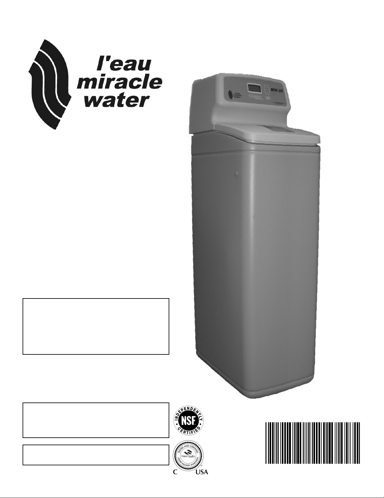
Unpacking and Inspection
The parts required to assemble and install the unit are included in a parts bag.
Thoroughly check the unit for possible shipping damage and parts loss. Also inspect and note any
damage to the shipping carton.
Remove and discard (RECYCLE) all packing materials. To avoid loss of small parts, we suggest
you keep the small parts in the parts bag until you are ready to use them.
DO NOT RETURN TO STORE
If you have any questions, missing parts or damage, please call 1-800-356-7851
Before you call please have your model number, date of purchase, water conditions
and number of people in your home.
For more installation or service information visit www.leaumiraclewater.ca
FOR FUTURE REFERENCE, ENTER THE FOLLOWING INFORMATION
MODEL NO. 1 _ _ _ _ _ _ _ _ _ _ _ _ _ _ _ _ _ _ _ _ _ _ _ INSTALLATION DATE _ _ _ _ _ _ _ _ _ _ _ _ _ _ _ _ _ _ _ _
SERIAL NO. 1 _ _ _ _ _ _ _ _ _ _ _ _ _ _ _ _ _ _ _ _ _ _ _ _ _ _ _ _ _ _ _ _ _ _ _ _ _ _ _ _ _ _ _ _ _ _ _ _ _ _ _
WATER HARDNESS _ _ _ _ _ _ _ _ _ _ _ _ _GPG IRON CONTENT _ _ _ _ _ _ _ _ _ _ _ _ _ _ _ _ _ _ _ _ _PPM
1 on registration decal
Miracle Water Installation & Operation Manual
3
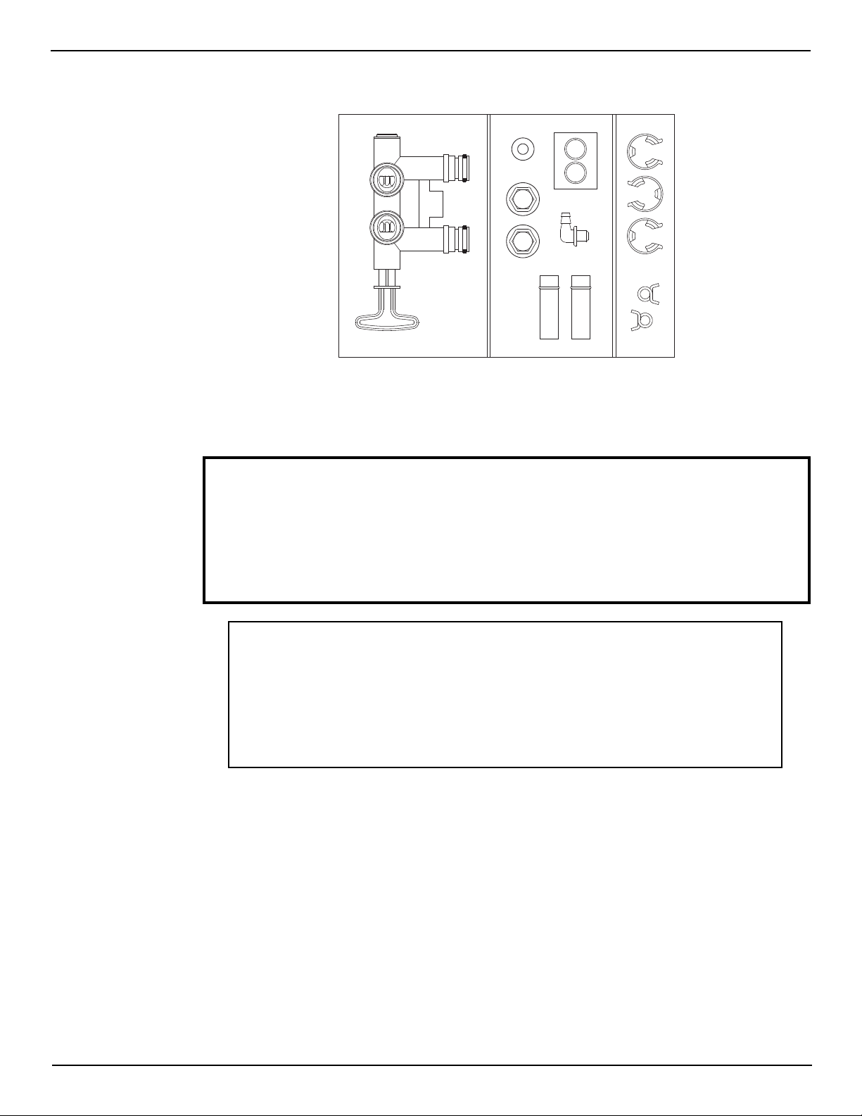
Softener Dimensions
MODEL NOMINAL RESIN TANK SIZE A B C
MW-30 9” Dia. x 35” 37” 33” 42”
Salt Storage Capacity
MW-30 - 150 lbs.
Wiring Schematic
4
Miracle Water Installation & Operation Manual
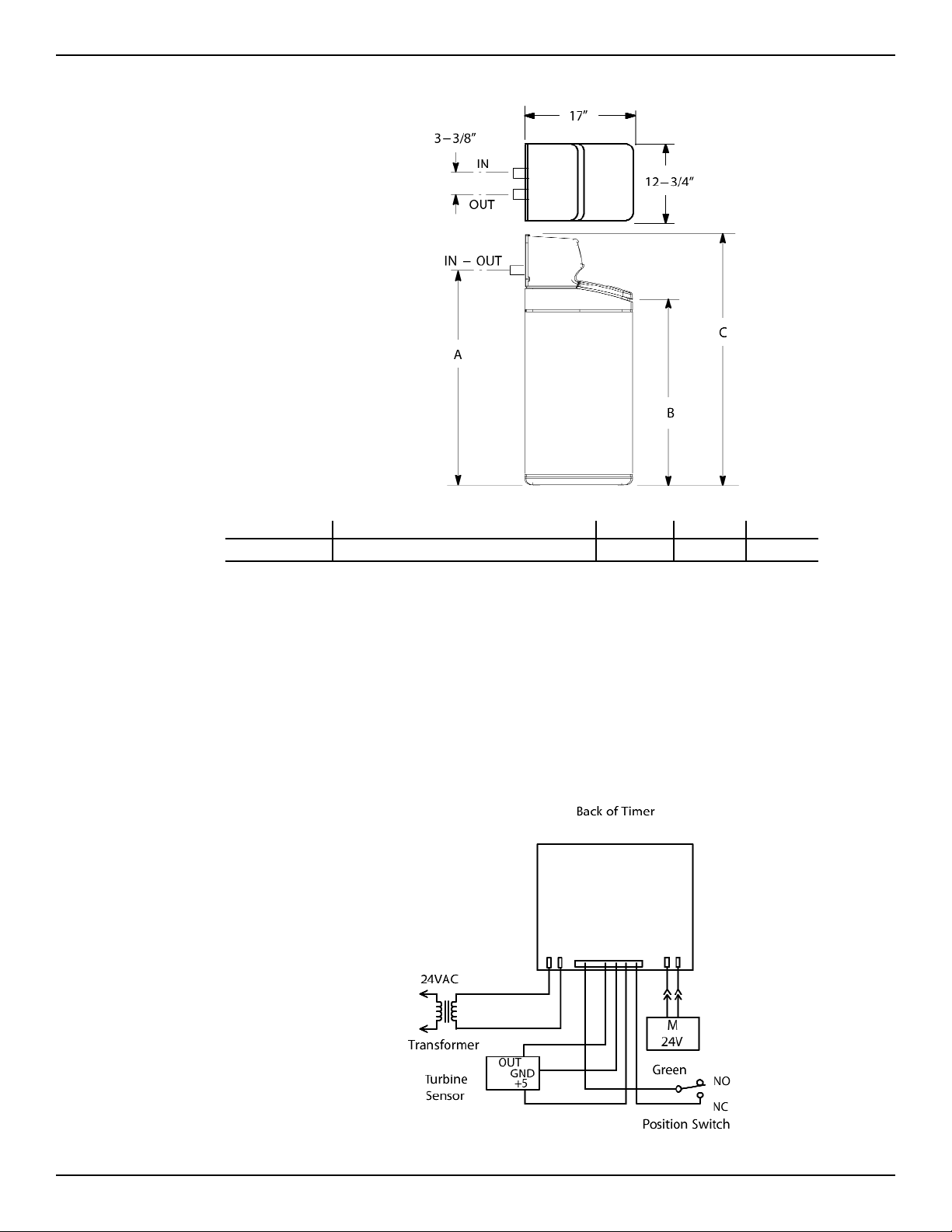
Miscellaneous Service Information
DESIGN SPECIFICATION MW-30
FILL CYCLE 1 FLOW .3 gpm
BRINE CYCLE 2 FLOW .22 gpm
BRINE RINSE CYCLE 2 FLOW .15 gpm
BACKWASH CYCLE (MAX.) 2 FLOW 2.0 gpm
FAST RINSE CYCLE (MAX.)
1 gallon per minute flow to brine tank
2 gallon per minute flow to drain
2 FLOW 2.0 gpm
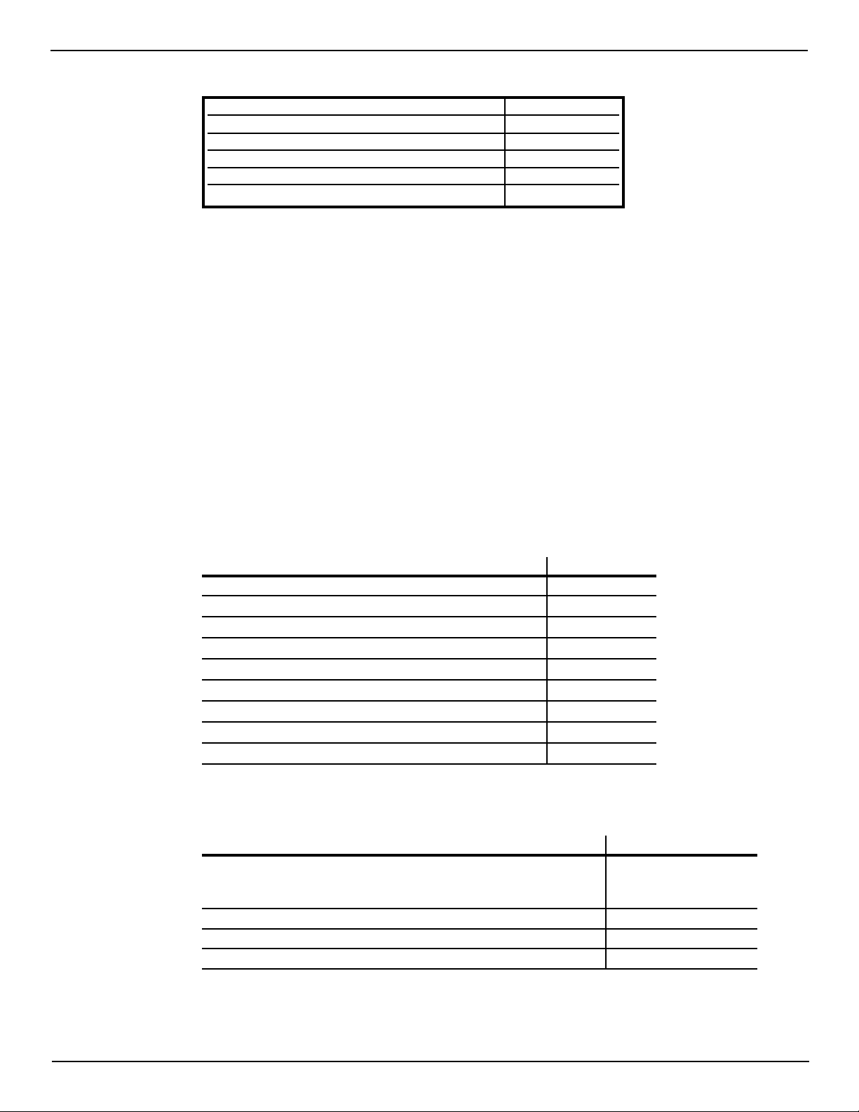
Product Specifications
This model is efficiency rated. The efficiency rating is valid only at the minimum salt dose. This
softener has a demand initiated regeneration (D.I.R.) feature that complies with specific performance specifications intended to minimize the amount of regenerant brine and water used in its
operation.
This softener has a rated softener efficiency of not less than 3,350 grains of total hardness
exchange per pound of salt (based on sodium chloride) and shall not deliver more salt than its
listed rating or be operated at a sustained maximum service flow rate greater than its listed rating. This softener has been proven to deliver soft water for at least ten continuous minutes at
the rated service flow rate. The rated salt efficiency is measured by laboratory tests described in
NSF/ANSI Standard 44. These tests represent the maximum possible efficiency that the system
can achieve. Operational efficiency is the actual efficiency after the system has been installed.
It is typically less than the rated efficiency, due to individual application factors including water
hardness, water usage, and other contaminants that reduce a softener's capacity.
MW-30
Rated Service Flow Rate (gpm) 8.0
Amount of High Capacity Ion Exchange Resin (cu. ft.) .82
Pressure Drop at Rated Service Flow (psig) 9.3
Water Supply Max. Hardness (gpg) 95
Water Supply Max. Clear Water Iron (ppm) 5
Water Pressure Limits (min./max. psi) 20 - 100
Min. - Max. Water Temperature (°F) 40 - 120
Min. Water Supply Flow Rate (gpm) 3
Max. Drain Flow Rate (gpm) 2.0
Performance Claims
MW-30
14,700 @ 2.9
Rated Softening Capacity (Grains @ Pound Salt Dose) 25,400 @ 8.0
30,100 @ 13.1
Rated Efficiency (Grains/Pound of Salt @ Minimum Salt Dose) 5,060 @ 2.9 lbs.
Water Used During Regeneration @ Minimum Salt Dose 2.3 gal. /1,000 grains
Total Water Used Per Regeneration @ Maximum Salt Dose 35.2 gallons
This system conforms to NSF/ANSI 44 for the specific performance claims as verified
and substantiated by test data.
Miracle Water Installation & Operation Manual
5

Safety Guides
Follow the installation instructions carefully. (Failure to install the unit properly voids the warranty.)
Before you begin installation, read this entire manual. Then, obtain all the materials and tools you
will need to make the installation.
Check local plumbing and electrical codes. The installation must conform to them.
Use only lead-free solder and flux for all sweat-solder connections, as required by state and fed-
eral codes.
Use care when handling the unit. Do not turn upside down, drop, or set on sharp protrusions.
Do not locate the unit where freezing temperatures occur. Do not attempt to treat water over 120°F.
Freezing, or hot water damage voids the warranty.
Avoid installing in direct sunlight. Excessive sun heat may cause distortion or other damage to
non-metallic parts.
The unit requires a minimum water flow of 3 gallons per minute at the inlet. Maximum allowable
inlet water pressure is 100 psi. If daytime pressure is over 80 psi, nighttime pressure may
exceed the maximum. Use a pressure reducing valve if necessary. (Adding a pressure reducing
valve may reduce the flow.)
The unit works on 24 volt-60 hz electrical power only. Be sure to use the included transformer
and plug it into a nominal 120V, 60 cycle household outlet that is grounded and properly protected by an overcurrent device such as a circuit breaker or fuse. If transformer is replaced, use only
the authorized service, Class II, 24V 10VA transformer.
This system is not intended to be used for treating water that is microbiologically unsafe or of
unknown quality without adequate disinfection before or after the system. For California installations the Salt Efficiency setting must be set to “ON”.
European Directive 2002/96/EC requires all electrical and electronic equipment to be disposed of according to Waste Electrical and Electronic Equipment (WEEE) requirements.
This directive or similar laws are in place nationally and can vary from region to region.
Please refer to your province and local laws for proper disposal of this equipment.
Water Conditioning Information
Water conditioning is the treatment of four general conditions. These are:
1. HARDNESS
2. IRON
3. ACIDITY
4. SEDIMENTS
1. HARDNESS is a term to describe the presence of calcium and magnesium minerals in water. A
chemical analysis accurately measures the amount of minerals in grain weight. For example,
one gallon of water with 5 grains per gallon (gpg) hardness has dissolved minerals, that if solidified, about equals the size of one ordinary aspirin tablet. One gallon of water, 25 gpg hard, has
a mineral content equal in size to 5 aspirin tablets. Water hardness varies greatly across the
country. It generally contains from 3 to 100 gpg.
Hard water affects living in general. Hardness minerals combine with soap to make a soap curd.
The curd greatly reduces the cleaning action of soap. Precipitated hardness minerals form a
6
Miracle Water Installation & Operation Manual

crust on cooking utensils, appliances, and plumbing fixtures. Even the tastes of foods are affected. A water softener removes the hardness minerals to eliminate these problems, and others.
Sodium Information: Water softeners using sodium chloride (salt) for regeneration and add
sodium to the water. Persons on sodium restricted diets should consider the added sodium as
part of their overall intake.
2. IRON in water is measured in parts per million (ppm). The total* ppm of iron, and type or types*,
is determined by chemical analysis. Four different types of iron in water are:
1 Ferrous (clear water),
2 Ferric (red water),
3 Bacterial and organically bound iron,
4 Colloidal and inorganically bound iron (ferrous or ferric).
*Water may contain one or more of the four types of iron and any combination of these. Total
iron is the sum of the contents.
1 Ferrous (clear water) iron is soluble and dissolves in water. It is usually detected by taking a
sample of water in a clear bottle or glass. Immediately after taking, the sample is clear. As the
water sample stands, it gradually clouds and turns slightly yellow or brown as air oxidizes the
iron. This usually occurs in 15 to 30 minutes. This unit will reduce moderate amounts of this
type of iron (see specifications).
When using the softener to remove Ferrous (clear water) iron, add 5 grains to the hardness setting for every 1 ppm of Ferrous (clear water) iron.
2 Ferric (red water), and 3 Bacterial and organically bound irons are insoluble. This iron is vis-
ible immediately when drawn from a faucet because it has oxidized before reaching the home.
It appears as small cloudy yellow, orange, or reddish suspended particles. After the water stands
for a period of time, the particles settle to the bottom of the container. Generally these irons are
removed from water by filtration. Chlorination is also recommended for bacterial iron. This unit
will not reduce ferric or bacterial iron.
4 Colloidal and inorganically bound iron is of ferric or ferrous form that will not filter or exchange
out of water. In some instances, treatment may improve colloidal iron water, but always CONSULT A QUALIFIED WATER CHEMISTRY LAB before attempting to treat it. Colloidal iron water
usually has a yellow appearance when drawn. After standing for several hours, the color persists and the iron does not settle, but remains suspended in the water.
Iron in water causes stains on clothing and plumbing fixtures. It negatively affects the taste of
food, drinking water, and other beverages. This unit will not reduce colloidal iron.
3. ACIDITY or acid water is caused by carbon dioxide, hydrogen sulfide, and sometimes industri-
al wastes. It is corrosive to plumbing, plumbing fixtures, water heaters, and other water using
appliances. In can also damage and cause premature failure of seals, diaphragms, etc., in water
handling equipment.
A chemical analysis is needed to measure the degree of acidity in water. This is called the pH
of water. Water testing below 6.9 pH is acidic. The lower the pH reading, the greater the acidity. A neutralizer filter or a chemical feed pump are usually recommended to treat acid water.
4. SEDIMENT is fine, foreign material particles suspended in water. This material is most often clay
or silt. Extreme amounts of sediment may give the water a cloudy appearance. A sediment fil-
ter installed ahead of the water softener normally corrects this situation.
Miracle Water Installation & Operation Manual
7
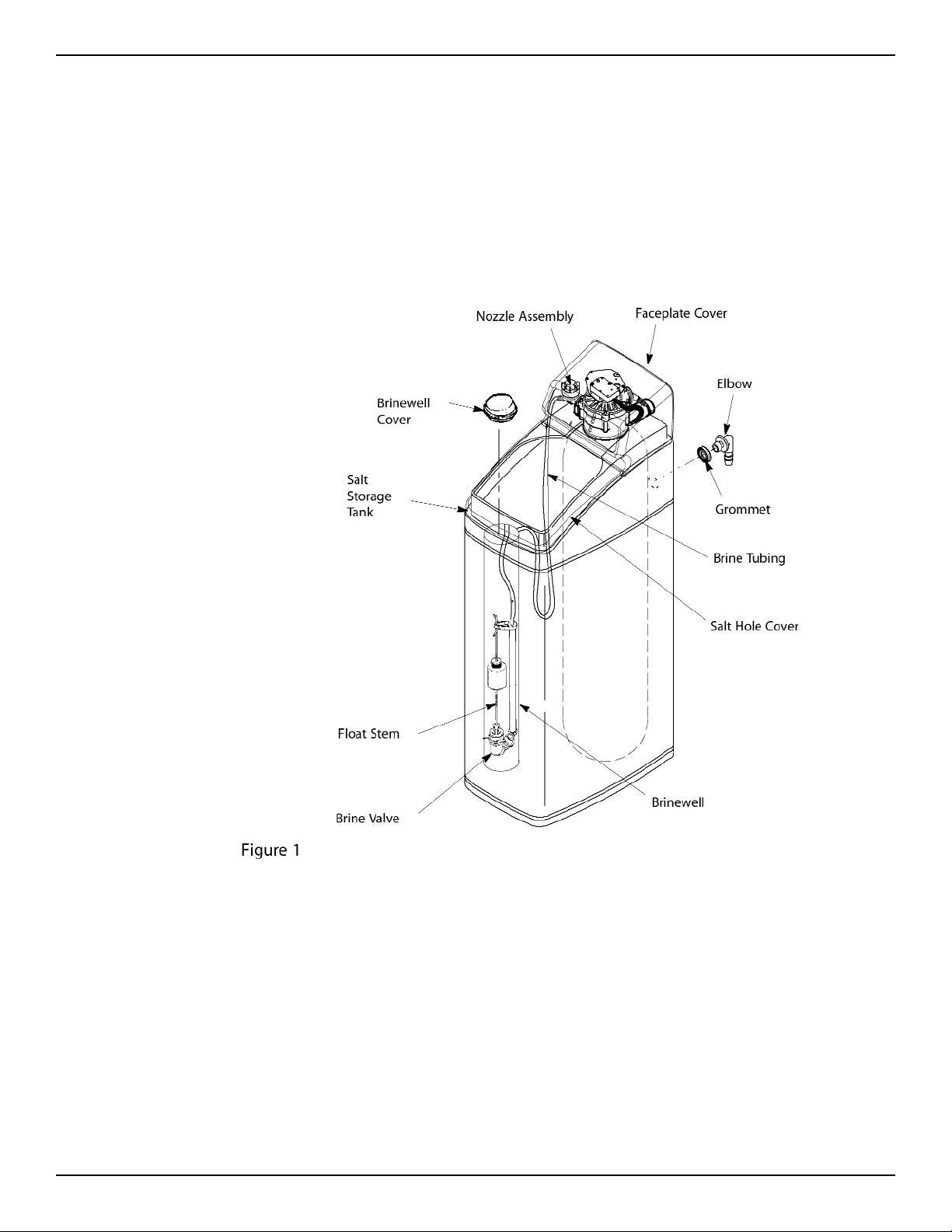
Assembly
1. Miracle Water models are factory assembled. During installation, remove the Salt Hole Cover.
Set aside to prevent damage. Check the brinewell to be sure it is secured and vertical (see
Figure 1). Slide Faceplate Cover forward to expose back valve assembly.
2. Lift the brine valve out of the brinewell. Be sure the float stem is parallel to stand tube so seals
will seat properly during operation. Replace the brine valve in the brinewell bottom and install
the Brinewell Cover.
3. Install the brine tank overflow grommet and elbow in the 13/16” diameter hole in the back of the
salt storage tank sidewall.
8
Miracle Water Installation & Operation Manual
Hard
Water
Conditioned
Water
Floor Drain
Salt Storage Tank
Overflow Hose*
1---1/2” Airgap
INLET
OUTLET
Valve
Drain
Hose*
Single
Bypass Valve
Transformer
To Timer
3/4” coupling
3/4” pipe and fittings
Copper tube
Gasket & Nut
Bypass valve
Clips
To Outside
Facets
*Do not tee these
drain lines together
3/4” pipe
3/4” coupling
Copper tube
Nut
Gasket
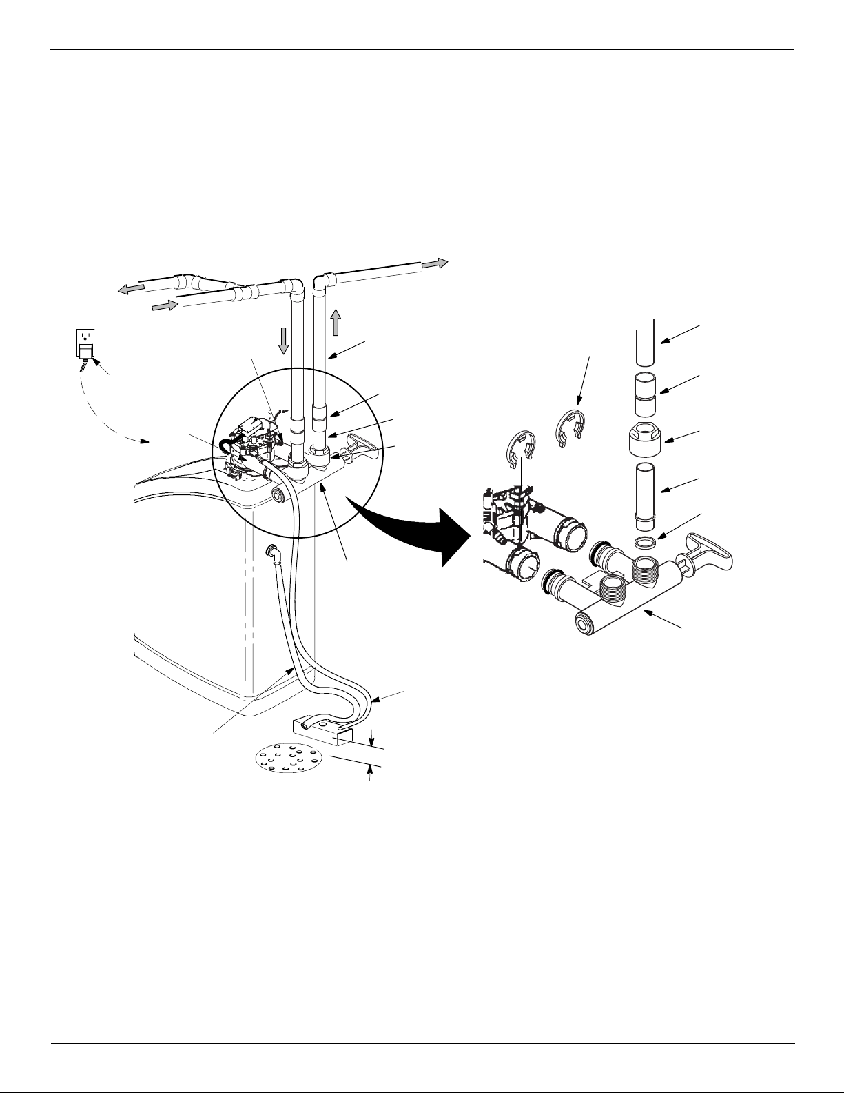
Planning Installation
Inlet - Outlet Plumbing Options
• ALWAYS INSTALL either a single bypass valve (included) or a 3 valve bypass system (not
included). Bypass valves allow you to turn off water to the softener for repairs if needed, but still
have water in house pipes.
• Use 3/4” (minimum) pipe and fittings.
• Use sweat copper... or, threaded pipe... or, PVC plastic pipe... or, other approved plumbing.
MAIN WATER PIPE
Figure 2
Tie or wire valve drain hose in place, to keep over
floor drain.
NOTE: Air gap requirements on Fig. 2
NOTE: Salt Hole and Faceplate cover not
shown for clarity of drawing.
NOTE: The bypass valve allows the water to
be turned off to the softener for
servicing, but still have water in the
house pipes.
Miracle Water Installation & Operation Manual
9

Other Requirements
• A 120V-60Hz, grounded electrical outlet (continuously ‘‘live’’) is needed nearby the unit.
• A drain is needed for regeneration discharge water. A floor drain, close to the unit, is preferred.
A laundry tub, standpipe, etc., are other drain options.
Tools and Materials You May Need
• Common Screwdriver • Tape Measure
•Pliers • Pipe and fittings as required
Soldered Copper
• Tubing cutter • LEAD-FREE solder and flux
• Propane torch •Emery cloth, sandpaper or steel wool
• Misc. fittings
Threaded
• Pipe cutter or hacksaw • Pipe joint compound
• Threading tool • Misc. fittings
CPVC Plastic
• Pipe cutter • Solvent cement
• Hacksaw • Primer
• Adjustable wrench • Misc. fittings
NOTE: The salt storage tank drain elbow accepts either 1/2” or 3/8” I. D. hose.
10
Miracle Water Installation & Operation Manual

*VALVE DRAIN OPTIONS: Flexible drain hose is not allowed in all localities (check your plumbing codes). For a rigid valve drain run, cut the barbed section off the drain fitting for access to the
1/4” pipe threads. Then plumb a rigid drain as needed (see Figure 4).
Select Installation Location
Consider all of the following when selecting an installation location for the unit.
• To condition all water in the home, install the unit close to the water supply inlet, and before all
other plumbing connections, EXCEPT outside water pipes. Outside faucets should remain on
hard water to avoid wasting conditioned water and salt.
• A nearby drain is needed to carry away regeneration discharge water. Use a floor drain, laundry
tub, sump, standpipe, etc., or other options (check your local codes).
• The unit works on 24 volts only. A transformer, with a 10’ power cord attached, is included to
reduce 120-60 Hz household electrical power. Provide an approved, grounded outlet within 10’
of the unit.
• Always install the unit BEFORE the water heater and after all other installed water condition-
ing equipment (see Figure 5 below).
Miracle Water Installation & Operation Manual
11

Installation
Step 1. Turn Off Water Supply
1. Close the main water supply valve, near the well pump or water meter.
2. Shut off the electric or fuel supply to the water heater.
3. Open all faucets to drain all water from the house pipes.
Step 2. Move the Unit into Place
Move the unit into installation position. Set it on a solid, smooth and level surface. If needed, place
the unit on a section of plywood, a minimum of 3/4” thick. Then, shim under the plywood to level
the unit, see Figure7.
CAUTION: DO NOT PLACE SHIMS DIRECTLY UNDER THE SALT STORAGE TANK. The
weight of the tank, when full of water and salt, may cause the tank to fracture at
the shim.
12
Visually check and remove any foreign materials from the valve inlet and outlet ports.
If not already done, put a light coating of silicone grease or Vaseline on the bypass valve o-rings.
Push the bypass valve into the softener valve as far as it will go. Snap the 2 large holding clips
into place, from the top down as shown in Figure 8.
CAUTION: Be sure the clips snap firmly into place so the bypass valve will not pull out.
Miracle Water Installation & Operation Manual

Step 3. Assemble Inlet and Outlet Plumbing
Measure, cut, and loosely assemble pipe and fittings from the main water pipe to the inlet and outlet ports of the valve.
Be sure hard water supply pipe goes to the valve inlet side.
NOTE: Inlet and outlet are marked on the valve. Trace the water flow direction to be sure.
CAUTION: Be sure to fit, align and support all plumbing to prevent putting stress on the
softener valve inlet and outlet. Undo stress may cause damage to the valve.
Step 4. Connect Inlet and Outlet Plumbing
Complete the inlet and outlet plumbing as applicable, below.
1. SOLDERED COPPER
a. Thoroughly clean and flux all joints.
b. Make all solder connections. Be sure to keep fittings fully together, and pipes square and
straight. DO NOT solder with installation adaptors or bypass valve attached to plumbing.
Soldering heat will damage the installation adaptors and valve.
2. THREADED PIPE
a. Apply pipe joint compound to all outside pipe threads.
b. Tighten all threaded joints.
3. PVC PLASTIC PIPE
a. Clean, prime and cement all joints, following the manufacturer’s instructions supplied with the
plastic pipe and fittings.
Step 5. Cold Water Pipe Grounding
WARNING: The house cold water pipe (metal only) is often used as a ground for the house
electrical system. The 3-valve bypass type of installation, shown in Figure. 2,
will maintain ground continuity. If you use a plastic bypass valve at the unit,
continuity is broken. To restore the ground, do the following.
Install a #4 copper wire across the removed section of main water pipe, securely clamping at both
ends, see Figure 9 (parts not included).
NOTE: Check local plumbing and electrical codes for proper installation of the ground
wire. The installation must conform to them. In Massachusetts, plumbing codes of
Massachusetts shall be adhered to. Consult with your licensed plumber.
Miracle Water Installation & Operation Manual
13

Step 6. Install Valve Drain Hose
Single Valve Bypass
PUSH IN
for Bypass
PULL OUT
for Service
NOTE: See valve drain options on page 11.
1. Connect a length of 3/8” or 7/16” I.D. hose (check codes) to the valve drain elbow, on the controller, see Figure 4. Use a hose clamp to hold the hose in place. Route the hose out through the
notch in the Faceplate Cover.
2. Run the hose to the floor drain, and as typically shown in Figure 2, tie or wire the end to a brick
or other heavy object. This will prevent ‘‘whipping’’ during regenerations. Be sure to provide a 1-
1/2” minimum air gap, to prevent possible sewer water backup.
NOTE: In addition to a floor drain, you can use a laundry tub, or standpipe as a good drain
point for this hose. Avoid long drain hose runs, or elevating the hose more than 8’
above the floor.
Step 7. Install Salt Storage Tank Overflow Hose
1. Connect a length of 3/8” I. D. hose to the salt storage tank overflow elbow and secure in place
with a hose clamp (see Figure 2).
2. Run the hose to the floor drain, or other suitable drain point no higher than the drain fitting on
the salt storage tank. (This is a gravity drain.) If the tank overfills with water, the excess water
flows to the drain point.
NOTE: Route the tubing neatly out of the way and cut it to the desired length.
DO NOT connect the valve drain tubing from step 6 to the salt storage tank over flow hose.
Step 8. Pressure Testing for Leaks
To prevent excessive air pressure in the unit and plumbing system, do the following steps
EXACTLY in order.
1. Fully open two or more softened cold water faucets nearby the unit.
2. Place the bypass valve(s) in “bypass” position. See Figure 10.
14
Miracle Water Installation & Operation Manual

3. Fully open the main water supply valve. Observe steady flow from the opened faucets, with no
air bubbles.
4. EXACTLY as follows, place bypass valve(s) in “service”.
a. SINGLE BYPASS VALVE: SLOWLY, move the valve stem toward “service”, pausing several
times to allow the unit to pressurize slowly.
b. 3-VALVE BYPASS: Fully close the bypass valve and open the outlet valve. SLOWLY, open
the inlet valve, pausing several times to allow the unit to pressurize slowly.
5. After about three minutes, open a hot water faucet for about one minute, or until all air is
expelled, then close.
6. Close all cold water faucets and check your plumbing work for leaks.
Step 9. Add Water and Salt to the Salt Storage Tank
1. Using a container, add about one gallon of clean water into the salt storage tank.
2. Add salt pellets to the salt storage tank.
NOTE: See page 22 for additional information on salt.
Step 10. Connect Transformer
NOTE: Check to be sure all leadwire connectors are secure on the back of the electronic
board.
CAUTION: Be sure all wiring is away from the valve gear and motor area, which rotates dur-
ing regenerations.
1. Plug the transformer into a continuously “live”, grounded house electrical outlet, approved by
local codes. THE UNIT WORKS ON 24V ONLY. DO NOT CONNECT WITHOUT THE TRANS-
FORMER.
Miracle Water Installation & Operation Manual
15

Step 11. Program the Controller
1. Install the salt hole and faceplate covers.
2. Complete the Programming Steps on Pages 17, 18 and 19.
Step 12. Sanitizing the Softener
Care is taken at the factory to keep your unit clean and sanitary. Materials used to make the unit
will not infect or contaminate your water supply, and will not cause bacteria to form or grow.
However, during shipping, storage, installing and operating, bacteria could get into the unit. For this
reason, sanitizing as follows is suggested1when installing.
1
Recommended by the Water Quality Association. On some water supplies, the unit may need periodic disinfecting.
1. Remove the Brinewell Cover and pour about 1-1/2 oz. (2 to 3 tablespoons) of common household bleach into the softener brinewell, Figure 1, page 8. Clorox, Linco, Bo Peep, White Sail, Eagle,
etc. are brand names of bleach readily available. Replace the Brinewell Cover.
2. Make sure the bypass valve(s) is in the “service” (open) position.
3. Start a recharge: Press the (RECHARGE) button and hold for 3 seconds
“RECHARGE NOW” begins to flash in the display. This recharge draws the sanitizing bleach into
and through the water softener. Any air remaining in the unit is purged to the drain.
4. After the recharge has completed, fully open a cold water faucet, downstream from the softener, and allow 50 gallons of water to pass through the system. This should take at least 20 minutes.
Close the faucet.
Step 13. Restart the Water Heater
Turn on the electricity or fuel supply to the water heater, and light the pilot, if applicable.
NOTE: The water heater is filled with HARD water and, as hot water is used, it refills with
conditioned water. In a few days, the hot water will be fully conditioned. To have
fully conditioned hot water immediately, wait until the recharge (Step 12) is over.
Then, drain the water heater until water runs cold.
, until
16
Miracle Water Installation & Operation Manual

Programming the Faceplate Timer
RECHARGE
TONIGHT (Press)
NOW (Hold for 3 seconds)
SELECT
MENU
www.leaumiraclewater.ca
1--800--356-7851
CE SOIR (Appuyer)
MAINTENANT (Tenir appuyer)
UP button
DOWN button
RECHARGE button
Display
SELECT/MENU button
Figure 12
If you have questions about installation, programming, operating and routine maintenance...
call 1-800-356-7851
When the transformer is plugged into the electrical outlet, a model code and a test number (example: J2.0), begins to flash in the faceplate display. Then, 12:00 AM and PRESENT TIME begins to
flash.
NOTE: If - - - - shows in the display, press the UP p or DOWN q button until LE31 shows.
Step 1. Set Time of Day
If the words PRESENT TIME do not show in the display, press the (Select/Menu) button
until they do.
1. Press the UP p or DOWN q buttons to set the present time. UP p moves the display ahead;
DOWN q moves the time backward.
Be sure AM or PM, is correct.
NOTE: Press buttons and quickly release to slowly advance the display. Hold for fast
Then, press the SELECT/ MENU button to set, and change to the flashing
SELECT
MENU
PRESENT TIME display.
SELECT
MENU
advance. This procedure applies for all following settings.
Miracle Water Installation & Operation Manual
17

Step 2. Set Water Hardness Number
1. Press the (Select/Menu) button once to display a flashing 25 and HARDNESS.
2. Press the UP p or DOWN q buttons to set your water hardness number.
NOTE: Be sure to enter the grains per gallon (gpg) hardness of your water supply on page
SELECT
MENU
4, for future reference. If your water supply contains iron, compensate for it by
adding to the water hardness number. For example, assume your water is 20 gpg
hard and contains 2 ppm iron. Add 5 to the hardness number for each 1 ppm of
iron. In this example, you would use 30 for your hardness number.
2 ppm iron x 5 = 10 +10
Step 3. Set Recharge (Regeneration) Time
1. Press the (Select/Menu) button once to display a flashing 2:00AM and RECHARGE
TIME.
SELECT
MENU
20 gpg hardness
(times) 30 HARDNESS NUMBER
If no change is desired, go to Step 4. If you want to change the recharge start time, press the
UP p or DOWN q buttons until the desired starting time shows.
18
Miracle Water Installation & Operation Manual

Step 4. Set Salt Efficiency
When this feature is ON, the unit will operate at salt efficiencies of 4000 grains of hardness per
pound of salt or higher. (May recharge more often using smaller salt dosage and less water).
1. Press and hold the (Select/Menu) button until the following screen is displayed.
SELECT
MENU
Once in this display, press the (Select/Menu) button and one of the following two dis-
SELECT
MENU
plays is shown.
2. Press the UP p or DOWN q buttons to set On or Off. When set to On, the efficiency icon will
be displayed in the upper right hand corner of the normal run display.
3. Press the (Select/Menu) button once again, to complete initial programming.
SELECT
MENU
If you have questions about installation, programming, operating and routine maintenance...
call 1-800-356-7851
Salt Efficiency Feature
Your Miracle Water Softener has a “High Efficiency” feature with an “ON” or “OFF” setting. This
softener setting is shipped in the “OFF” position, which utilizes the maximum rated capacity while
most often achieving maximum salt efficiencies. Turning this setting to the “ON” position may initiate more frequent recharges, however it will operate at 4000 grains per pound of salt or higher.
If you wish to turn the Salt Efficiency feature “ON” ( icon will show in display), follow the instructions on this page.
Miracle Water Installation & Operation Manual
19

Customizing Features/Options
Recharge Now
If you have guests, or other times when more water than usual is used, you could begin to run out
of conditioned water. If the unit is not scheduled to regenerate for another day or two, you could
get hard water until then. If this occurs, do the following to start an immediate regeneration.
• Press and hold the (Recharge) button until RECHARGE NOW flashes in the display,
NOTE: Avoid using hot water while the conditioner is regenerating, because the water
Recharge Tonight
If you do not want to start an immediate recharge, but would like an extra recharge at the next preset recharge time, do the following to schedule a recharge.
• Press and release (do not hold) the (Recharge) button. RECHARGE TONIGHT flash-
RECHARGE
and the softener enters the fill cycle of regeneration right away. RECHARGE NOW will flash during the regeneration. When over, full water conditioning capacity is restored.
RECHARGE NOW Initiated
heater will refill with bypass hard water.
RECHARGE
es in the display, and the softener will recharge at the next recharge time. RECHARGE NOW
will flash during the regeneration. When over, full water conditioning capacity is restored.
Timer “Power-Outage Memory”
If electrical power to the timer is lost, ‘‘memory’’ built into the timer circuitry will keep all settings for
several hours. While the power is out, the display is blank and the unit will not regenerate. When
electrical power is restored, the following will occur.
1. You have to reset the present time only if the display is flashing. The HARDNESS and
RECHARGE TIME never require resetting unless a change is desired. Even if the timer is incorrect after a long power outage, the softener works as it should to keep your water soft. However,
regenerations may occur at the wrong time of day until you reset the timer to the correct time of
day.
NOTE: If the unit was regenerating when power was lost, it will now finish the cycle.
RECHARGE TONIGHT Initiated
20
Miracle Water Installation & Operation Manual

Customizing Features/Options
Adjustable Backwash
If your incoming water supply has higher sediments or iron, a longer Backwash and/or Fast Rinse
time may help in keeping the unit cleaner.
1. Press and hold the (Select/Menu) button until the following screen is displayed.
SELECT
MENU
Once in this display, press the (Select/Menu) button until the following display is shown.
2. Press the UP p or DOWN q buttons to change the backwash time from 0 to 60 minutes.
3. Press the (Select/Menu) twice to return to the normal run display.
Adjustable Fast Rinse
1. Press and hold the (Select/Menu) button until the following screen is displayed.
Once in this display, press the (Select/Menu) button until the following display is shown.
SELECT
MENU
SELECT
MENU
SELECT
MENU
SELECT
MENU
2. Press the UP p or DOWN q buttons to change the backwash time from 0 to 60 minutes.
3. Press the (Select/Menu) to return to the normal run display.
SELECT
MENU
Miracle Water Installation & Operation Manual
21

Routine Maintenance
Refilling With Salt
Remove the Salt Storage Tank Front Cover and check the salt storage level frequently. If the conditioner uses all the salt before you refill it, you will get hard water. Until you have established a
refilling routine, check the salt every two or three weeks. ALWAYS add if less than 1/3 full. Be sure
the Brinewell Cover is on.
NOTE: In humid areas, it is best to keep the salt storage level lower, and to refill more often.
SALT NOT RECOMMENDED: Rock salt, high in impurities, block, granulated, table, ice melting,
ice cream making salts, etc., are not recommended.
SALT WITH IRON REMOVING ADDITIVES: Some salts have an additive to help a water conditioner handle iron in a water supply. These are not recommended for Miracle Water units.
Breaking A Salt Bridge
Sometimes, a hard crust or salt bridge forms in the brine tank. It is usually caused by high humidity or the wrong kind of salt. When the salt bridges, an empty space forms between the water and
the salt. Then, salt will not dissolve in the water to make brine. Without brine, the resin bed does
not regenerate and you will have hard water.
If the storage tank is full of salt, it is hard to tell if you have a salt bridge. Salt is loose on top, but
the bridge is under it. Take a broom handle, or like tool, and push it straight down into the salt. If
a hard object is felt, it’s most likely a salt bridge. Carefully push into the bridge in several places to
break it.
DO NOT use any sharp or pointed objects as you may puncture the tank.
22
Miracle Water Installation & Operation Manual

Cleaning the Nozzle and Venturi
A clean nozzle and venturi (see Figure 14) is a must for the conditioner to work properly. This small
unit creates the suction to move brine from the brine tank, into the resin tank. If it should become
plugged with sand, silt, dirt, etc., the conditioner will not work, and you will get hard water.
To get to the nozzle and venturi, slide Faceplate Cover forward. Be sure the unit is in soft water
cycle (no water pressure at nozzle and venturi). Then, holding the nozzle and venturi housing with
one hand, turn off the cap. Do not lose the o-ring seal. Lift out the screen support and screen.
Then, remove the nozzle and venturi. Wash the parts in warm, soapy water and rinse in fresh
water. If needed, use a small brush to remove iron or dirt. Be careful not to scratch, misshape, etc.,
surfaces of the nozzle and venturi. Also, check and clean the gasket and flow plug(s).
Carefully replace all parts in the correct order. Lubricate the o-ring seal with silicone grease and
locate in position. Install and tighten the cap, by hand only. Do not overtighten and break the
cap or housing. If you have questions about routine maintenance...
call 1-800-356-7851
Miracle Water Installation & Operation Manual
23

Protect the Water Softener from Freezing
If the softener is installed where it could freeze (summer cabin, lake home, etc.), you must drain
all water from it to stop possible freeze damage. To drain the softener:
1. Close the shut-off valve on the house main water pipe, near the water meter or pressure tank.
2. Open a faucet in the soft water pipes to vent pressure in the softener.
3. Refer to Figure 10 on page 16. Move the stem in a single bypass valve to bypass. Close the
inlet and outlet valve in a 3-valve bypass system, and open the bypass valve. If you want water
in the house pipes again, reopen the shut-off valve on the main water pipe.
4. Unplug the transformer at the wall outlet. Remove the salt hole cover and the main cover. Take
off both drain hoses.
5. Carefully remove the large holding clips at the softener inlet and outlet. Separate the softener
from the copper tubes, or from the bypass valve.
6. Remove the brinewell cover and disconnect the brine valve tubing at the nozzle and venturi
assembly (see Figure 1, page 9). Lift the brine valve out of the brinewell. Tip the brine valve
upside down to drain water.
7. Looking at Figure 15, lay a piece of 2 inch thick board near the floor drain. Move the softener
close to the drain. SLOWLY and CAREFULLY, tip it over until the rim rests on the wood block
with the inlet and outlet over the drain. Do not allow the softener’s weight to rest on the inlet and
outlet fittings or they will break.
8. Tip the bottom of the softener up a few inches and hold until all water has drained. Leave the
softener laying like this until you are ready to use it. Plug the inlet and outlet with rags to keep
dirt, bugs, etc. out.
Figure 15
floor
drain
wood block
24
Miracle Water Installation & Operation Manual

Troubleshooting Guide
Tools Needed for Most Repairs: 5/16 Hex Driver, Phillips Screwdriver, Needle-nose Pliers
PROBLEM CAUSE SOLUTION REPAIR KIT(S)
No Soft Water 1. No Salt in the storage tank a. Add salt (see page 22)
No Soft Water Timer
Display Blank
No Soft Water
Salt Level Not Dropping
No Soft Water, Salt
Storage Tank Full of
Water, Water Running To
The Drain (While Unit Is
In The Soft Water Cycle)
Water Hard Sometimes 1. Time setting wrong a. Check and change time setting None
Iron In Water 1. Clear water iron in water supply
Resin In Household Plumb ing, Resin Tank Leaking
Salt Storage Tank Leaking 1. Crack in brine tank a. Replace salt storage tank assembly (page
Motor Stalled Or Clicking 1. Motor defective or inner valve defect causing
Error Code E1, E2, E3, or
E4 appears
Error Code E5 appears 1. Faceplate a. Replace Electronic Control Board Electronic Control
1. Transformer unplugged at wall outlet, or
power cable disconnected from back of faceplate, Transformer defective
2. Fuse blown, circuit breaker popped, or circuit
switched off. (See page 20 “Timer Power
Outage Memory).
3. Timer control board defective a. Replace Electronic Control Board (page 29) Timer Control Board
1. Salt in storage tank bridged a. Refer to page 22 to break. None
2. Manual bypass valve(s) in bypass position a. See page 15 figure 10. Move stern in single
1. Dirty, plugged or damaged nozzle & venturi a. Take apart, clean and inspect nozzle and
2. Inner valve defect causing leak a. Replace seals and rotor (page 29) Rotor/Seal Kit
3. Valve drain hose plugged a. Hose must not have any kinks, sharp bends
4. Valve drain line and Salt Storage Tank over-
flow drain connected together by a tee.
5. Low or high system water pressure (low pres-
sure may disrupt brine draw during recharge,
high pressure may cause inner valve parts failure)
6. Brine valve float kit dirty or defective a. Clean Brine or replace valve float kit assem-
7. Leak between valve and resin tank assembly a. Replace Tank/Valve O-Rings Tank/Valve O-ring Kit
2. Incorrect water hardness setting a. Refer to page 18 to find correct settings None
3. Incorrect model code programmed a. Refer to page 17 to find correct settings None
4. Hot water being used when softener is regen-
erating
5. Possible increase in water hardness a. Test the raw water for hardness and iron
6. Leaking faucet or toilet valve. Excessive
water usage.
2. Iron in soft water
3. Bacterial or organic bound iron
1. Crack in distributor or riser tube a. Replace resin tank assembly (page 29) Resin Tank Assembly
high torque on motor
1. Wiring Harness or Connection to Position Switch
2. Switch
3. Valve Defect Causing High Torque
4. Motor Inoperative
b. Use Recharge Now feature (page 20)
a. Check for loss of power and correct. Reset
timer and use the Recharge Now feature
(page 20)
a. Replace fuse, reset circuit breaker, or switch
circuit and use the Recharge Now feature
(page 20).
bypass to service
venturi (see page 23)
or any water flow blockage (see page 9)
a. Disconnect tee, run separate drain lines. None
a. If pressure is low, increase well pump output
to a minimum 20 psi. Add a pressure, reducing valve in the supply pipe to the softener, if
daytime pressure is over 100 psi.
bly (page 29)
a. Avoid using hot water while the softener is
regenerating as the water heater will fill with
hard water. Check timer for correct settings
and program the time accordingly (page 17)
a. A small leak will waste hundreds of gallons
of water in a few days. Fix all leaks and
always fully close faucets.
a. Test the raw water for hardness and iron
and program the time accordingly (page 17)
b. Clean resin bed with Resin Bed Cleaner
c. Cannot be treated by water softener
29)
a. Replace Rotor/Seal Kit (page 29)
b. Replace Motor & Switch
a. Replace Wiring Harness or Connection to
Position Switch
b. Replace Switch
c. Replace Rotor Seal Kit
d. Replace Motor
NEEDED
None
Transformer
None
None
Nozzle Kit
None
None
Float Kit
None
None
None
None
Salt Storage Tank
Assembly
Rotor/Seal Kit
Motor/Switch Kit
Motor/Switch Kit
Rotor/Seal Kit
Board Kit
PROCEDURE FOR REMOVING ERROR CODE FROM FACEPLATE: 1. Unplug transformer from outlet- - - - 2. Correct defect-
- - - 3. Plug in transformer- - - - 4. Wait for 8 minutes. The error code will return if the defect was not corrected.
Need help troubleshooting? Call 1-800-356-7851
Miracle Water Installation & Operation Manual
25

Automatic Electronic Diagnostics
The faceplate has a self-diagnostic function for the electrical system (except input power and/or
water meter). The faceplate monitors electronic components and circuits for correct operation. If a
malfunction occurs, an error code appears in the faceplate display.
The troubleshooting chart on page 26 shows the error codes that could appear, and the possible
defects for each code.
While an error code appears in the display, all faceplate buttons are inoperable except the
SELECT/MENU button. SELECT/MENU remains operational so the service person can perform
the Manual Advance Diagnostics, see below, to further isolate the defect.
Manual Advance Diagnostics
Use the following procedures to advance the unit through the regeneration cycles to check operation. Remove the Faceplate Cover to observe cam and switch operation during valve rotation.
1. Press and hold (Select/Menu) for 3 seconds until 000 --shows in the display.
SELECT
MENU
2. The first 3 digits indicate water meter operation as follows:
000 (steady) = Soft water not in use, and no flow through the meter.
—OPEN A NEARBY SOFT WATER FAUCET —
000 to 199 (continual) = Repeats display for each gallon of water passing through the meter.
NOTE: If you don’t get a reading in the display, with faucet open, pull the sensor from the
valve outlet port. Pass a small magnet back and forth in front of the sensor. You
should get a reading in the display. If you get a reading, unhook the in and out
plumbing and check the turbine for binding.
26
3. The letter (P) and dash (or dashes) indicate POSITION switch operation. If the letter appears,
the switch is closed. If the dash shows, the switch is open.
4. Use the Recharge button to manually advance the valve into each cycle and check
RECHARGE
correct switch operation.
Miracle Water Installation & Operation Manual

NOTE: Be sure water is in contact with the salt, and not separated by a salt bridge...
see page 23.
5. While in this diagnostic screen, the following information is available and may be beneficial for
various reasons. This information is retained by the computer from the first time electrical power
is applied to the face plate.
a. Press UP p to display the number of days this face plate has had electrical power applied.
b. Press DOWN q to display the number of regenerations initiated by this face plate since the
LE code number was entered.
SELECT
6. Press and hold the (Select/Menu) button until LE31 shows in the display.
MENU
This code identifies the softener model. If the wrong number shows, the softener will operate
on incorrect programming.
7. Return the present time display — Press the (Select/Menu) button.
SELECT
MENU
8. To change LE number — Press the UP p or DOWN q button until the correct code shows.
Then, press the (Select/Menu) button to return to the present time display.
SELECT
MENU
Resetting to Factory Defaults
To reset the electronic controller to its factory default for all settings (time, hardness, etc.):
SELECT
1. Press the (Select/Menu) button and hold it until the display changes twice to show
“CODE” and the flashing model code.
2. Press the UP p button (a few times, if necessary) to display a flashing “SoS”.
3. Press the (Select/Menu) button, and the electronic controller will restart.
4. Set the present time, hardness, etc., as described on pages 17 & 18.
MENU
SELECT
MENU
Miracle Water Installation & Operation Manual
27

Manual Advance Regeneration Check
This check verifies proper operation of the valve motor, brine tank fill, brine draw, regeneration flow
rates, and other controller functions. Always make the initial checks, and the manual initiated diagnostics.
NOTE: The faceplate display must show a steady time (not flashing). If an error code
shows, first press the (Select/Menu) button to enter the diagnostic display.
1. Press the (Recharge) button and hold in for 3 seconds. RECHARGE begins to flash
RECHARGE
SELECT
MENU
as the softener enters the fill cycle of regeneration. Remove the brinewell cover and, using a
flashlight, observe fill water entering the tank.
a. If water does not enter the tank, look for an obstructed nozzle, venturi, fill flow plug, brine
tubing, or brine valve riser pipe.
2. After observing fill, press the (Recharge) button to move the softener into brining. A
RECHARGE
slow flow of water to the drain will begin. Verify brine draw from the brine tank by shining a flashlight into the brinewell and observing a noticeable drop in the liquid level.
NOTE: Be sure a salt bridge is not preventing water with salt contact.
a. If the unit does not draw brine, check for (most likely to least likely)
- Dirty or defective nozzle and venturi, page 23
- Nozzle and venturi not seated on the gasket, or gasket defective
- Restriction in valve drain, causing a back-pressure (bends, kinks, elevated too high, etc.),
installation Step 6 on page 14
- Obstruction in brine valve or brine tubing
- Inner valve failure (obstructed outlet disc, wave washer defective, etc.)
NOTE: If water system pressure is low, an elevated drain hose may cause back pressure,
stopping brine draw.
3. Again, press the (Recharge) button to move the softener into backwash. Look for a
RECHARGE
fast flow of water from the drain hose.
a. An obstructed flow indicates a plugged top distributor, backwash flow plug, or drain hose.
4. Press the (Recharge) button to move the softener into fast rinse. Again look for a fast
RECHARGE
drain flow. Allow the softener to rinse for a few minutes to flush out any brine that may remain
in the resin tank from the brining cycle test.
5. To return the softener to service, press the (Recharge) button.
RECHARGE
28
Miracle Water Installation & Operation Manual

Softener Components
Power Supply Kit
P/N 7238426
Electronic Control Board
P/N 7327534
Resin Tank Assembly
P/N 7269273
Float Kit
P/N 7238476
Valve Kit
P/N 7238557
Bypass Valve
P/N 7129871
Motor Switch Kit
P/N 7285910
Valve Cover
P/N 7331266
Motor Plate
P/N 7231385
Cam & Gear Kit
P/N 7254252
Installation Adaptor Kit
P/N 7254260
Faceplate & Salt
Hole Cover Kit
P/N 7301473
Rotor/Seal Kit
P/N 7238468
Locking Plate
P/N 7225499
Nozzle & Venturi Kit
P/N 7238450
Salt Storage Tank
Assembly
P/N 7238523
Turbine & Sensor Kit
P/N 7249948
Miracle Water Installation & Operation Manual
Clips – P/N 7116713
29

Warranty
MIRACLE WATER RESIDENTIAL WARRANTY
Miracle Water guarantees to the original owner, that:
For a period of ten (10) years from the date of purchase, the salt storage tank and fiberglass mineral tank will not rust, corrode, leak, burst, or in any other manner, fail to perform their proper functions; and that
For a period of one (1) year from the date of purchase, all other parts will be free of defects in material and workmanship and
will perform their normal functions.
If, during such respective period, a part proves to be defective, Miracle Water will ship a replacement part, directly to your home,
without charge. Labor necessary to maintain this product is not covered by the product warranty.
If you have questions regarding a Miracle Water product, need assistance with installation or trouble shooting, wish to order a
part or report a warranty issue, we are just a phone call away. Simply dial 1-800-356-7851 for assistance, or visit www.leaumiraclewater.ca
Miracle Water, 5240 Bradco Blvd, Mississauga (Ontario), L4W 1G7
General Provisions
The above warranties are effective provided the water conditioner is operated at water pressures not exceeding 125 psi, and at
water temperatures not exceeding 120°F; provided further that the water conditioner is not subject to abuse, misuse, alteration,
neglect, freezing, accident or negligence; and provided further that the water conditioner is not damaged as the result of any
unusual force of nature such as, but not limited to, flood, hurricane, tornado or earthquake.
Miracle Water is excused if failure to perform its warranty obligations is the result of strikes, government regulation, materials
shortages, or other circumstances beyond its control.
*THERE ARE NO WARRANTIES ON THE WATER CONDITIONER BEYOND THOSE SPECIFICALLY DESCRIBED ABOVE.
ALL IMPLIED WARRANTIES, INCLUDING ANY IMPLIED WARRANTY OF MERCHANTABILITY OR OF FITNESS FOR A PARTICULAR PURPOSE, ARE DISCLAIMED TO THE EXTENT THEY MIGHT EXTEND BEYOND THE ABOVE PERIODS. THE
SOLE OBLIGATION OF MIRACLE WATER UNDER THESE WARRANTIES IS TO REPLACE OR REPAIR THE COMPONENT
OR
PART WHICH PROVES TO BE DEFECTIVE WITHIN THE SPECIFIED TIME PERIOD, AND MIRACLE WATER IS NOT LIABLE
FOR CONSEQUENTIAL OR INCIDENTAL DAMAGES. NO MIRACLE WATER DEALER, AGENT, REPRESENTATIVE, OR
OTHER PERSON IS AUTHORIZED TO EXTEND OR EXPAND THE WARRANTIES EXPRESSLY DESCRIBED ABOVE.
Some provinces do not allow limitations on how long an implied warranty lasts or exclusions or limitations of incidental or consequential damage, so the limitations and exclusions in this warranty may not apply to you. This warranty gives you specific legal
rights, and you may have other rights which vary from state to state. This warranty applies to consumer-owned installations only.
30
Miracle Water Installation & Operation Manual
 Loading...