


INSTALLATION INSTRUCTIONS
LED High Bay Light Engine Module
Document: Date
Created By: DCR#
FIGURE 1
LPN00266X01A0_A 2014-07-31
TMT 2014-285
E-AB1L22
E-PB1L22
E-AB1L11
E-PB1L11
CAUTIONS
IMPORTANT SAFEGUARDS
When using electrical equipment, basic safety precautions should
always be followed including the following:
READ AND FOLLOW ALL SAFETY
INSTRUCTIONS
1. DANGER- Risk of shock- Disconnect power before installation.
DANGER – Risque de choc – Couper l’alimentation avant
l’installation.
2. This luminaire must be installed in accordance with the NEC
or your local electrical code. If you are not familiar with these
codes and requirements, consult a qualied electrician.
Ce produit doit être installé conformément à NEC ou votre code
électrique local. Si vous n’êtes pas familier avec ces codes et
ces exigences, veuillez contacter un électricien qualié.
3. Suitable for operation in ambient not exceeding 40°C
Peut être utilisé à une température ambiante n’excédant pas
40°C
4. Min 75°C supply conductors.
Les fils d’alimentation 75°C min.
5. Products with prismatic reflectors are not intended for use in
environments containing airborne corrosive agents such as
chemical solvents, cleaners, or cutting fluids.
6. Cast locknuts should not be used for fixture support to conduit.
7. Attach reflector properly to light engine module before applying
voltage to fixture.
SAVE THESE INSTRUCTIONS FOR
FUTURE REFERENCE
Pendant
Adjustment
3/4” ( 19mm )
Knockouts
“L” Channel
Holes for Surface Mounting
and Junction Box Mounting
3/4” ( 19mm )
Pendant Mount Hole
1/2” ( 13mm )
Knockouts
HINGED SPLICE BOX MOUNTING
1. Remove hinged splice box cover from top of housing by loosening
screw and sliding box to the right and up from “L” channel.
Unhook from hinge plate. See Figure 1.
2. Attach hinged splice box cover to mounting surface.
For conduit entering the hinge splice box from the top:
Use 3/4" threaded conduit, along with two locknuts (one for inside
the hinged splice box and one for outside the hinged splice box).
Pull supply leads into position from customer supplied conduit.
Note: The luminaire should already be factory set for correct
balance. However, should you need to, the luminaire may be
balanced by loosening (2) retention screws for pendant adjustment
on the top of the hinged splice box and sliding the adjustment plate
as necessary for correct balance. Tighten (2) retention screws when
nished. See Figure 1.
For surface mounting the hinge splice box:
Use designated mounting holes on top of hinge splice box. See
Figure 1. For conduit entering the hinge splice box from the side,
use appropriately-sized threaded conduit (1/2" or 3/4"), along with
two locknuts (one for inside the hinged splice box and one for
outside the hinged splice box).
3. Attach one end of the hinged splice box to luminaire by aligning
hinge slots on Mounting Bracket with hinges (on splice box), and
then inserting the hinges into the slots.
4. Make the following wire connections and then push the leads into
hinged splice box:
• Connect supply ground to luminaire ground (green).
• Connect supply common to luminaire neutral (white)
lead.
• Connect supply black to luminaire black (line).
5. Secure other end of the hinged splice box to luminaire by sliding
screw on Mounting Bracket up and over in “L” channel on the
hinged splice box. See Figure 1.
6. Secure luminaire to hinged splice box by tightening screw.
HINGED SPLICE BOX WITH HOOK MOUNTING
Note: Reflectors and optional lenses are sent in a separate
carton from this light engine module.
www.e-conolight.com | 888.243.9445 | FAX: 262.504.5409
1. Remove the original hinged splice box cover from top of housing
by loosening screw and sliding box to the right and up from “L”
channel. Unhook from hinge plate and discard. See Figure 1.
2. On the hinged splice box with the hook (purchased as an
accessory), push down on retainer spring until top of spring is free
of luminaire hook. See Figure 2 on back page.
INSTALLATION INSTRUCTIONS
LED High Bay Light Engine Module
Document: Date
Created By: DCR#
LPN00266X01A0_A 2014-07-31
TMT 2014-285
3. Slide hook into securely mounted customer supplied eye hanger
and return retainer spring to original position.
NOTE: The luminaire should already be factory set for correct
balance. However, should you need to, the xture may be
balanced by loosening the (2) hook adjustment retention screws
on the top of the housing and sliding the hook as necessary for
correct balance. Tighten (2) hook adjustment retention screws
when nished. See Figure 2 on back page.
For conduit entering the hinge splice box from the side:
Use appropriately-sized threaded conduit (1/2” or 3/4”), along with
two locknuts (one for inside the hinge box and one for outside the
hinge box).
For cord and plug accessory:
Insert strain relief and cord wires into side 1/2” knockout.
NOTE: For connecting the exible cord to the wiring box for branch
supply, suitable Listed cord connector of the involved cord size and
standard conduit opening shall be used in order to maintain strain
relief.
3. Attach one end of the hinged splice box to luminaire by aligning
hinge slots on Mounting Bracket with hinges (on splice box), and
then inserting the hinges into the slots.
4. Make the following wire connections and then push the leads into
hinged splice box:
• Connect supply ground to luminaire ground (green).
• Connect supply common to luminaire neutral (white)
lead.
• Connect supply black to luminaire black (line).
5. Secure other end of the hinged splice box to luminaire by sliding
screw on Mounting Bracket up and over in “L” channel on the
hinged splice box. See Figure 1.
6. Secure luminaire to hinged splice box by tightening screw
7. If installing with optional cord and plug, locate the plug and
connect to the proper socket according to the plug.
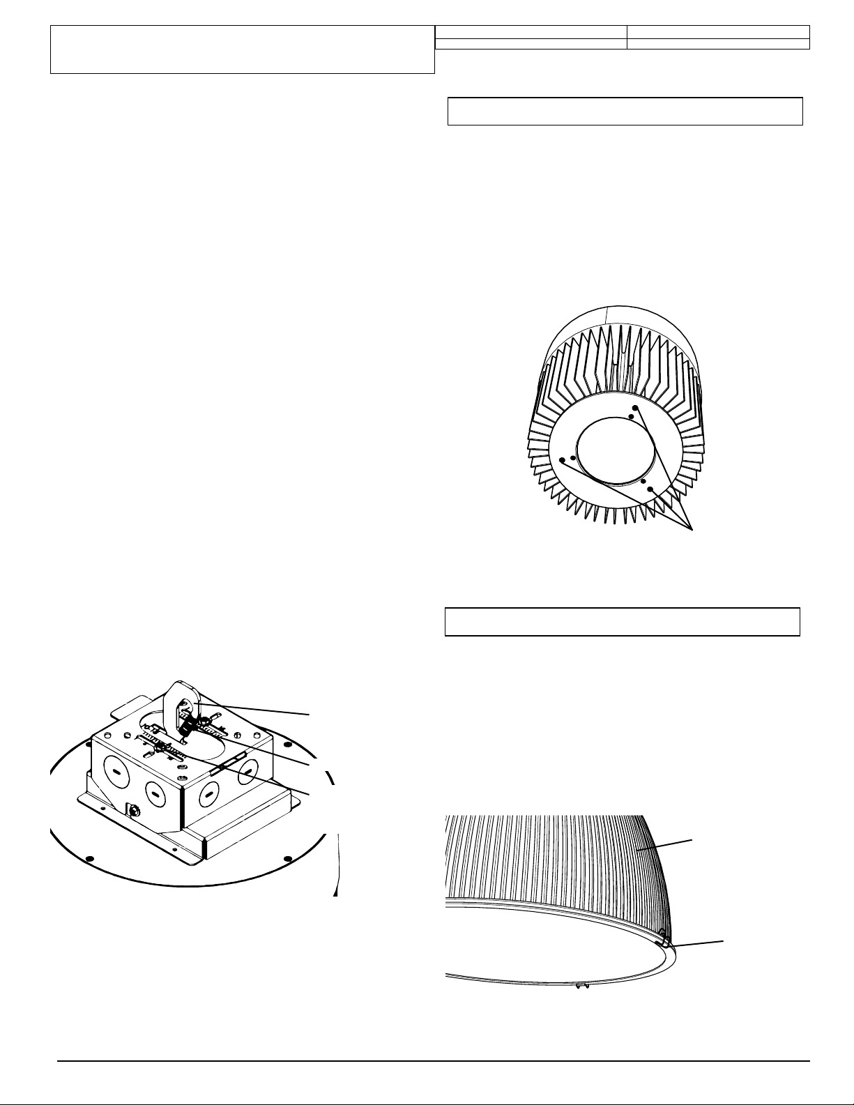
REFLECTOR INSTALLATION
NOTE: Products with prismatic reectors are not intended for use in
environments containing airborne corrosive agents such as chemical
solvents, cleaners, or cutting uids.
1. Loosen the (3) screws on the bottom of the luminaire, shown in
Figure 3, at least 0.1 inch.
2. Bring reector up to housing and line up the (3) screws from Step
1, with the keyhole slots on the reector.
3. Rotate reector, turn clockwise and tighten the (3) screws from
Step 1
FIGURE 3
Loosen
Screws
FIGURE 2
Luminaire Hook
Retainer Spring
(2) Hook
Adjustment
Retention
Screws
ATTACHING LENS TO REFLECTOR
NOTE: Lens is attached the same to the each version of the reector,
Prismatic and Aluminum, as described below. Prismatic Reector is
shown in the gure for illustration purposes.
1. With reector attached to light engine module, secure lens to
reector with the four spring latches attached to the lens. See
Figure 4.
FIGURE 4
Reflector
(4) Spring
Latches
www.e-conolight.com | 888.243.9445 | FAX: 262.504.5409
 Loading...