

Page 1
Smart Thermostat
User Guide
Model: RETST700SYS
CLICK HERE
CLIQUEZ ICI
TO VIEW THE SMART THERMOSTAT
USER GUIDE IN FRENCH
POUR CONSULTER LE GUIDE
D’UTILISATION DU THERMOSTAT
INTELLIGENT EN ANGLAIS
Page 2

User Guide Table of Contents
Overview .................................................................................................................................................................... 3
Items Included in the Box ..........................................................................................................................................3
Homescreen Overview ..............................................................................................................................................4
Icons to Become Familiar With .................................................................................................................................5
Standby Screen .........................................................................................................................................................6
System Modes ......................................................................................................................................................7–9
Connecting to WiFi .................................................................................................................................................. 10
Weather ...................................................................................................................................................................11
Menu Options .......................................................................................................................................................... 12
Settings .............................................................................................................................................................12–17
Settings > Basic ..........................................................................................................................................12–13
Settings > Time ................................................................................................................................................. 14
Settings > Humidity ....................................................................................................................................14–15
How to Test a Humidifier ...................................................................................................................................15
Settings > Away Settings ..................................................................................................................................15
Settings > Vacation ...........................................................................................................................................16
Settings > Fan .............................................................................................................................................16–17
Settings > Zoning Settings ...............................................................................................................................17
Schedules ................................................................................................................................................................ 18
Status ......................................................................................................................................................................19
Furnace Status ..................................................................................................................................................19
AC/HP Status .................................................................................................................................................... 19
Air Handler Status ............................................................................................................................................. 19
Zoning Status .................................................................................................................................................... 20
Service ...............................................................................................................................................................21–22
Service > Current ..............................................................................................................................................21
Service > History ............................................................................................................................................... 21
Service > Alerts ................................................................................................................................................. 21
Service > Support ............................................................................................................................................. 22
Service > Equipment .........................................................................................................................................22
Water Heating ..........................................................................................................................................................23
Zoning .....................................................................................................................................................................23
EcoNet Smart Thermostat Installation Instructions .................................................................................................24
Safety Considerations ....................................................................................................................................... 24
Thermostat Location ......................................................................................................................................... 24
Wiring Considerations ....................................................................................................................................... 25
Mounting EcoNet Smart Thermostat ................................................................................................................ 26
Wiring Remote Temperature Sensor .................................................................................................................27
Installer Settings ................................................................................................................................................ 28–31
Furnace Settings ......................................................................................................................................... 28–29
How to Connect a Ventilator to an EcoNet HVAC System ...............................................................................30
AC/HP Settings ........................................................................................................................................... 30–31
Thermostat Settings ..........................................................................................................................................31
Air Handler Settings .......................................................................................................................................... 32
Caring for your Thermostat .....................................................................................................................................32
Amazon Alexa Enabled Devices .............................................................................................................................. 33
Regulatory and Warranty Information .....................................................................................................................34
EcoNet® Smart Thermostat User Guide 2
Page 3

EcoNet Smart Thermostat User Guide
R C S1 S2 E1 E2
QUICK START
GUIDE
R C S1 S2 E1 E2
QUICK START
GUIDE
R C S1 S2 E1 E2
QUICK START
GUIDE
R C S1 S2 E1 E2
QUICK START
GUIDE
R C S1 S2 E1 E2
The EcoNet® Smart Thermostat is an easy-to-use programmable thermostat that provides complete control over
your home’s smart air and water comfort systems. It’s smart enough to alert you when an issue is detected, yet
it’s designed to be simple to operate with an intuitive touchscreen interface. And it has built-in WiFi so you can
monitor your system and adjust temperatures and schedules while on-the-go.
More than a thermostat, it’s part of an intuitive system that maximizes comfort and efficiency while offering
complete peace of mind—so you can stay focused on what matters most.
Items Included in the Box
EcoNet Smart Thermostat
Wall Mounting Plate
Ferrite Toroid
Mounting Screws and Drywall Anchors
Lens Cloth
Quick Start Guide
EcoNet Smart Thermostat
Wall Mounting Plate
Ferrite Toroid
x 2
x 2
Mounting Screws
and Drywall Anchors
Lens Cloth
QUICK START
GUIDE
EcoNet® Smart Thermostat User Guide 3> Return to Table of Contents
Page 4
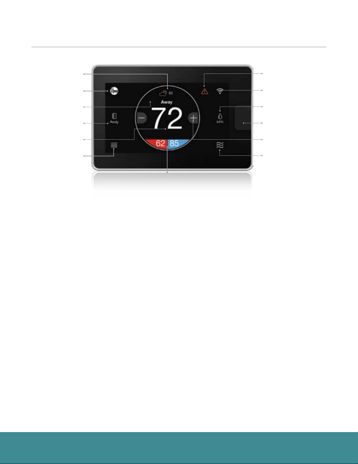
Homescreen Overview
Weather
Brand Logo
Messaging Bar
One-Touch Away
Indoor Temperature
Menu
System Set Point
What This Means to Me, the Homeowner:
Weather
Current weather condition and outside
temperature; tap to see forecast
Alert
WiFi
Humidity
Motion Sensor
Temperature Adjustment
System Mode
Alert
Indicates an important reminder, minor alert, or
critical alarm; tap for additional details
Brand Logo
Tap to access contractor information and
support help
One-Touch Away
Tap once to enter preset Away settings; tap
again to return to previous settings or
resume schedule
Indoor Temperature
Shows the current temperature
inside your home
Menu
Tap to navigate to the full Menu where you can
change basic settings, customize your
schedule and more
WiFi
Current WiFi signal strength; tap to start the
setup process
Humidity
Current relative humidity in your home; tap to
configure to your preference
System Mode
Tap to navigate to Mode selection screen
(auto/heat/cool/e-heat/fan/off)
EcoNet® Smart Thermostat User Guide 4> Return to Table of Contents
Page 5
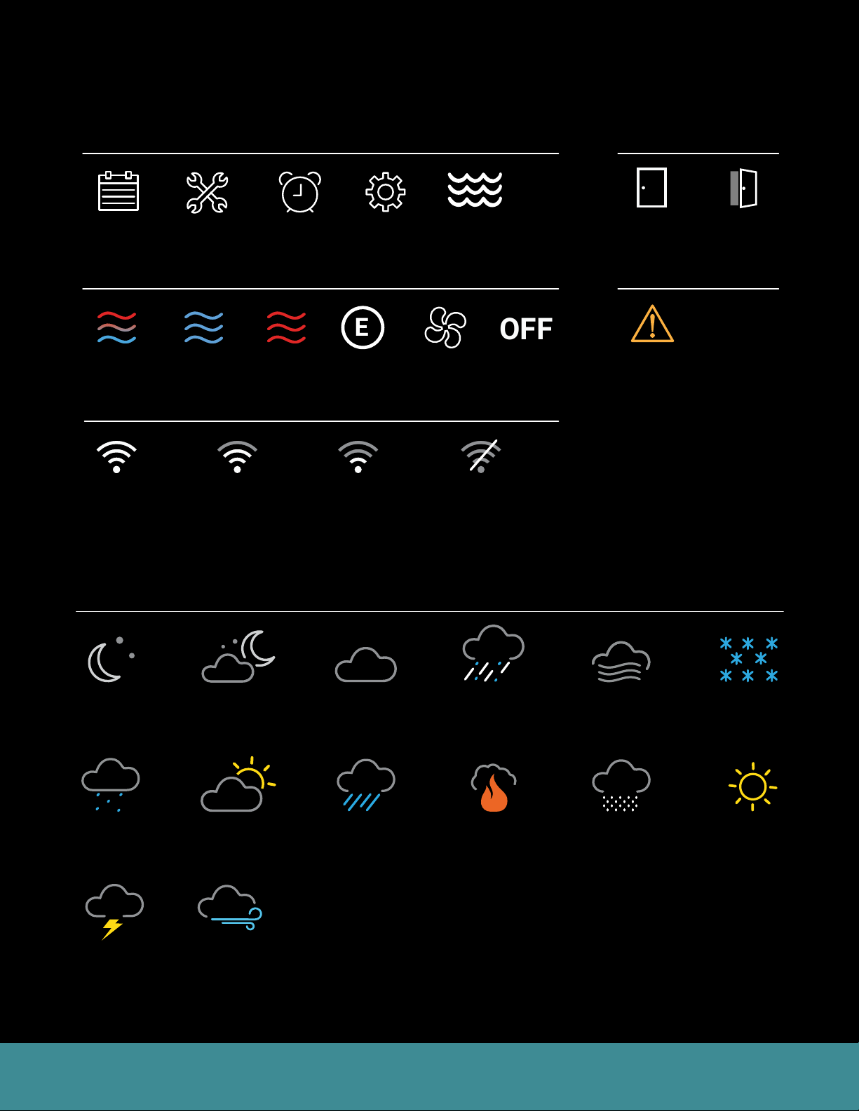
Icons to Become Familiar With
Raining Thunderstorm Snowing Freezing Rain
Partly Sunny
Cloudy Windy
Cloudy Windy
Raining Thunderstorm Snowing Freezing Rain
Raining Thunderstorm Snowing Freezing Rain
Cloudy Windy
Smoke Frost
Cloudy Windy
# 2 Cloudy
# 3 Freezing Rain
Sunny Partly Cloudy/
Partly Sunny
Cloudy Windy
Smoke Frost
Raining Thunderstorm Snowing Freezing Rain
E
OFF
Menu
Home & Away
Schedule
Service
Settings
System Operation
Auto Cooling Heating Fan OnlyEmergency
WiFi Signal
Connected
Strong Signal
Connected
Medium Signal
Connected
Low Signal
Weather
Heat
Status
Water
Heater
Power Off
Not
Connected
Home Away
Alerts
Alert
Clear
Night
Mist Smoke
Cloudy
Night
Partly
Sunny
Cloudy
Rainy
Freezing
Rain
Storms
Windy
Fog
Snowing
Frost
Sunny
EcoNet® Smart Thermostat User Guide 5> Return to Table of Contents
Page 6
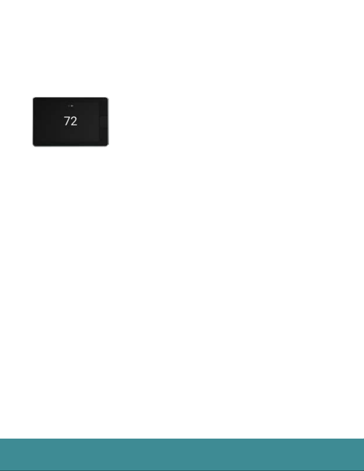
Standby Screen
If the thermostat has not been touched for 30 seconds, the screen dims and the standby screen activates
displaying indoor temperature and outdoor weather conditions. If an alert or alarm is present, the alert / alarm
icon will be displayed as well.
The motion sensor will automatically wake the thermostat and activate the home screen as you approach.
The standby screen can be turned off by disabling the back-light under basic
settings (Menu > Settings > Basic)
EcoNet® Smart Thermostat User Guide 6> Return to Table of Contents
Page 7
System Modes
Zoning System Test
T957_O Low Refrigerant Pressure
21
status: Setting airflow
CFM: 840
54
E HeatEFan
OFF
Cool
Heat
Auto
Zoning System Test
T957_O Low Refrigerant Pressure
21
status: Setting airflow
CFM: 840
54
E HeatECool
Auto
Heat
Fan
OFF
Zoning System Test
T957_O Low Refrigerant Pressure
21
status: Setting airflow
CFM: 840
54
E Heat
E
Fan
OFF
Cool
Heat
Auto
Zoning System Test
T957_O Low Refrigerant Pressure
21
status: Setting airflow
CFM: 840
54
The EcoNet Smart Thermostat will call for heat or cool based on the current settings and temperature. Cooling
and heating equipment may have a delay period before operation is enabled. The delay can be up to 5 minutes
(if the mode was changed right after equipment turns off). Status screen will show a “Hold-Off Timer” for
Equipment State.
Basic Settings
68
Backlight Enabled?
Outside Temp Selection?
Home
BACK
Backlight Enabled?
Outside Temp Selection?
Home 44%
Away
BACK
BACK
BACK
Backlight Enabled?
Outside Temp Selection?
Home 44%
Away
BACK
BACK
BACK
Backlight Enabled?
Outside Temp Selection?
Home
BACK
80
Yes
Away
Internet
71
75
OFF
62 85
Basic Settings
Installer Checkout
Select a Mode
68
80
80
80
Yes
Away
Group 1
Resume Schedule
Internet
71
36
72
75
71
Refrigeration
Cooling to
OFF
34
85
65
70
Basic Settings
Installer Checkout
Select a Mode
68
80
80
80
Yes
Away
Group 1
Resume Schedule
Internet
71
36
72
75
71
Refrigeration
Cooling to
OFF
34
85
65
70
Basic Settings
68
80
Yes
Away
Internet
71
75
OFF
62 85
!
Dining Room
Zone 4
!
Linearize Dampers
Dining Room
UNITS
Basement
Zone 4
!
Linearize Dampers
Dining Room
UNITS
Basement
!
Dining Room
Zone 3
47%
44%
Zone 3
47%
61%
44%
Zone 3
47%
61%
44%
Zone 3
47%
44%
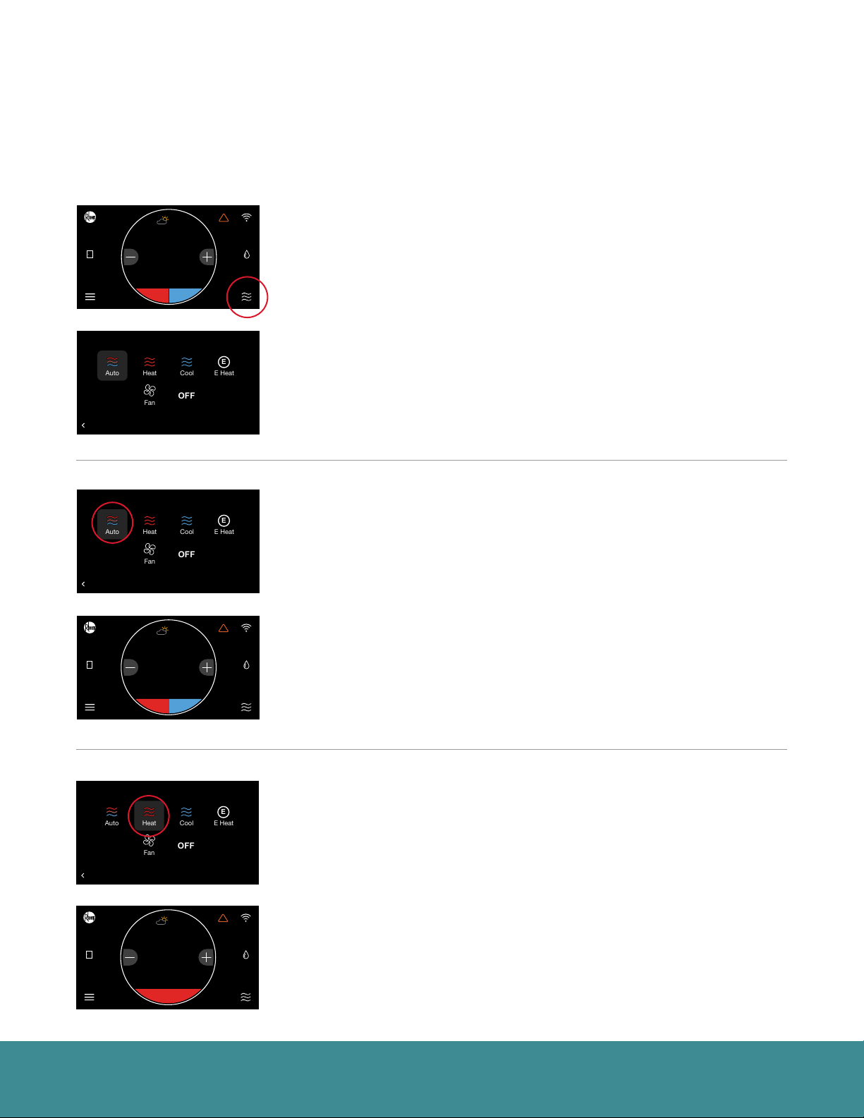
Select the mode icon in the bottom right corner of the home screen to quickly
change the operating mode.
Select from Auto, Heat, Cool, E-Heat, Fan and Off
Auto – Activates the heating or cooling system as required to keep your home
within the configured range of set point temperatures. Select the desired
set point, and then use the large adjustment buttons to set the desired
temperature. To adjust your cooling set point, tap the set point on the right it will turn blue, then adjust using the plus and minus buttons. The current
temperature in the center of the screen will temporarily be replaced by the
set point in large font during temperature adjustments.
Note: The default deadband or separation between the heating and cooling set points is 2 degrees.
Backlight Enabled?
Outside Temp Selection?
Home 44%
Away
BACK
BACK
BACK
Backlight Enabled?
Outside Temp Selection?
Home 44%
Home
Away
BACK
BACK
Basic Settings
Installer Checkout
Select a Mode
68
80
80
80
Yes
Away
Group 1
Resume Schedule
Internet
71
36
72
75
71
Refrigeration
Cooling to
OFF
34
85
65
70
Basic Settings
Installer Checkout
68
80
80
80
80
Yes
Away
Group 1
Resume Schedule
Internet
71
36
72
75
71
75
Refrigeration
Cooling to
OFF
34
85
65
70
62
Zone 3
Zone 4
!
Linearize Dampers
47%
61%
44%
Dining Room
UNITS
Basement
Zone 3
Zone 4
!
!
Linearize Dampers
47%
61%
44%
44%
Dining Room
UNITS
Basement
Heat – Turns on heating when the current temperature drops below your set
point temperature. When there is an active call for heating, the words ‘Heating
To’ will appear above the heating set point.
(Heating set point screen)
EcoNet® Smart Thermostat User Guide 7> Return to Table of Contents
Page 8
System Modes (con’t)
Zoning System Test
T957_O Low Refrigerant Pressure
21
status: Setting airflow
CFM: 840
54
E Heat
E
Heat
Auto
Cool
Fan
OFF
Zoning System Test
T957_O Low Refrigerant Pressure
21
status: Setting airflow
CFM: 840
54
E Heat
E
Fan
OFF
Cool
Heat
Auto
Zoning System Test
T957_O Low Refrigerant Pressure
21
status: Setting airflow
CFM: 840
54
E Heat
E
Fan
OFF
Cool
Heat
Auto
Zoning System Test
T957_O Low Refrigerant Pressure
21
status: Setting airflow
CFM: 840
54
E Heat
E
Fan
OFF
Cool
Heat
Auto
Zoning System Test
T957_O Low Refrigerant Pressure
21
status: Setting airflow
CFM: 840
54
Basic Settings
Installer Checkout
Select a Mode
68
80
80
Backlight Enabled?
Outside Temp Selection?
Home 44%
Away
BACK
BACK
BACK
Backlight Enabled?
Outside Temp Selection?
Home 44%
Home
Away
BACK
BACK
Backlight Enabled?
Outside Temp Selection?
Home 44%
Away
BACK
BACK
BACK
80
Yes
Away
Group 1
Resume Schedule
Internet
71
36
72
75
71
Refrigeration
Cooling to
OFF
34
85
65
70
Basic Settings
Installer Checkout
68
80
80
80
80
Yes
Away
Group 1
Resume Schedule
Internet
71
36
72
75
71
75
Refrigeration
Cooling to
OFF
34
85
65
70
85
Basic Settings
Installer Checkout
Select a Mode
68
80
80
80
Yes
Away
Group 1
Resume Schedule
Internet
71
36
72
75
71
Refrigeration
Cooling to
OFF
34
85
65
70
Zone 4
!
Linearize Dampers
Dining Room
UNITS
Basement
Zone 4
!
!
Linearize Dampers
Dining Room
UNITS
Basement
Zone 4
!
Linearize Dampers
Dining Room
UNITS
Basement
Zone 3
47%
61%
44%
Zone 3
47%
61%
44%
44%
Zone 3
47%
61%
44%
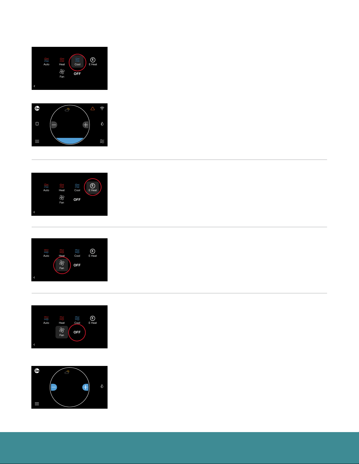
Cool – Turns on cooling when the current temperature rises above your set
point temperature. When there is an active call for cooling, the words ‘Cooling
To’ will appear above the cooling set point.
(Cooling set point screen)
E-Heat (Heat Pump Systems Only) – The emergency heat option is a manual
setting, not an automatic function initiated by the heat pump thermostat. The
purpose of the emergency heat setting is to bring the backup heat source
online immediately to deliver 100% of the home’s heating demand while
simultaneously locking out the heat pump.
Basic Settings
Installer Checkout
Select a Mode
68
80
80
Backlight Enabled?
Outside Temp Selection?
Home 44%
Away
BACK
BACK
BACK
Backlight Enabled?
Outside Temp Selection?
Home 44%
Away
BACK
BACK
BACK
80
Yes
Away
Group 1
Resume Schedule
Internet
71
36
72
75
71
Refrigeration
Cooling to
OFF
34
85
65
70
Basic Settings
Installer Checkout
Select a Mode
68
80
80
80
Yes
Away
Group 1
Resume Schedule
Internet
71
36
72
75
71
Refrigeration
Cooling to
OFF
34
85
65
70
68
Zone 4
!
Linearize Dampers
Dining Room
UNITS
Basement
Zone 4
!
Linearize Dampers
Dining Room
UNITS
Basement
71
OFF
Dining Room
Zone 3
47%
61%
44%
Zone 3
47%
61%
44%
Zone 3
47%
Fan Only – While in Fan Only mode, the heating/cooling equipment is turned
off. Use the plus or minus adjustment buttons to navigate between fan
speeds from Low to High. Press Mode again to reactivate a heating or cooling
mode. Fan only is a manual override of a set schedule. If a schedule is being
followed, the fan speed will return to the scheduled fan speed when you
reactivate the heating/cooling equipment. You can set continuous fan when in
Heating, Cooling or Auto mode from the Settings screen.
Off – The system will not actively heat or cool your home.
If you have an EcoNet Zoning System and the EcoNet Zone Control heat set
point is set to 50°F (10°C) or the cool set point is set to 92°F (33°C), the Zone
Control will default to Off.
EcoNet® Smart Thermostat User Guide 8> Return to Table of Contents
Page 9
System Modes (con’t)
Zoning System Test
T957_O Low Refrigerant Pressure
21
status: Setting airflow
CFM: 840
54
Zoning System Test
T957_O Low Refrigerant Pressure
21
status: Setting airflow
CFM: 840
54
Zoning System Test
T957_O Low Refrigerant Pressure
21
status: Setting airflow
CFM: 840
54
Basic Settings
Installer Checkout
68
80
80
80
Backlight Enabled?
Outside Temp Selection?
Home 44%
Home
Away
BACK
BACK
Backlight Enabled?
Outside Temp Selection?
Home 44%
Away
BACK
BACK
Backlight Enabled?
Outside Temp Selection?
Home 44%
Away
BACK
BACK
80
Yes
Away
Group 1
Resume Schedule
Internet
71
36
72
75
71
75
Refrigeration
Cooling to
OFF
62 85
34
85
65
70
Basic Settings
Installer Checkout
68
80
80
80
Yes
Away
Group 1
Resume Schedule
Internet
71
36
72
75
71
80
Refrigeration
Cooling to
OFF
34
85
65
70
Basic Settings
Installer Checkout
68
80
80
80
Yes
Away
Group 1
Resume Schedule
Internet
71
36
72
75
71
63
Refrigeration
Cooling to
OFF
34
85
65
70
Zone 4
!
!
Linearize Dampers
Dining Room
UNITS
Basement
Zone 4
!
Linearize Dampers
Dining Room
UNITS
Basement
Zone 4
!
Linearize Dampers
Dining Room
UNITS
Basement
Zone 3
47%
61%
44%
44%
Zone 3
47%
61%
44%
42%Home
Zone 3
47%
61%
44%
42%Home
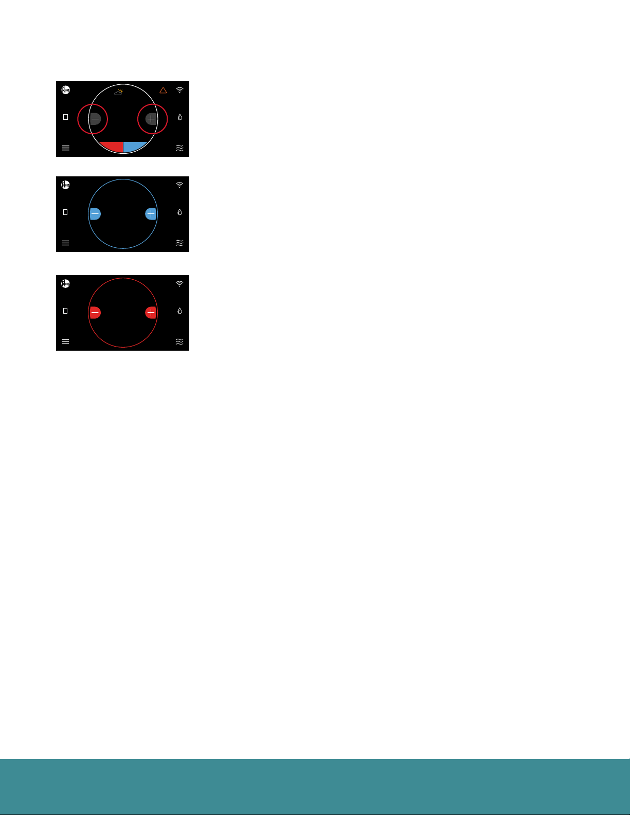
You can manually adjust the temperature from the Home Screen by touching
the plus and minus buttons. When the set point is being changed, the ring
will either turn blue or red—depending on the mode of operation—and
the new set point is displayed in the center of the screen. If Auto mode is
selected, press the lower left set point (red) for heat or lower right set point
(blue) for cool.
(Cooling set point adjustment)
(Heating set point adjustment)
EcoNet® Smart Thermostat User Guide 9> Return to Table of Contents
Page 10
Connecting to WiFi
Zoning System Test
T957_O Low Refrigerant Pressure
21
status: Setting airflow
CFM: 840
54
Zoning System Test
T957_O Low Refrigerant Pressure
21
status: Setting airflow
CFM: 840
54
Zoning System Test
T957_O Low Refrigerant Pressure
21
status: Setting airflow
CFM: 840
54
Zoning System Test
T957_O Low Refrigerant Pressure
21
status: Setting airflow
CFM: 840
54
Your EcoNet Smart Thermostat supports WiFi 802.11 b/g/n. WiFi is normally configured during initial setup. You
may, however, be required to reconfigure the settings if your WiFi network settings change.
Connecting to WiFi will enable voice control through Amazon Alexa1 devices, send local weather and allow you
to remotely manage your comfort and receive critical alarms should something ever go wrong. To save time, we
recommend having your home WiFi network password and your Internet-connected smartphone or tablet close
to the thermostat before you begin.
1. Download the EcoNet App2 and ensure your smartphone or tablet is already connected to your home
WiFi network.
2. Select ‘Create Account’ and follow the instructions.
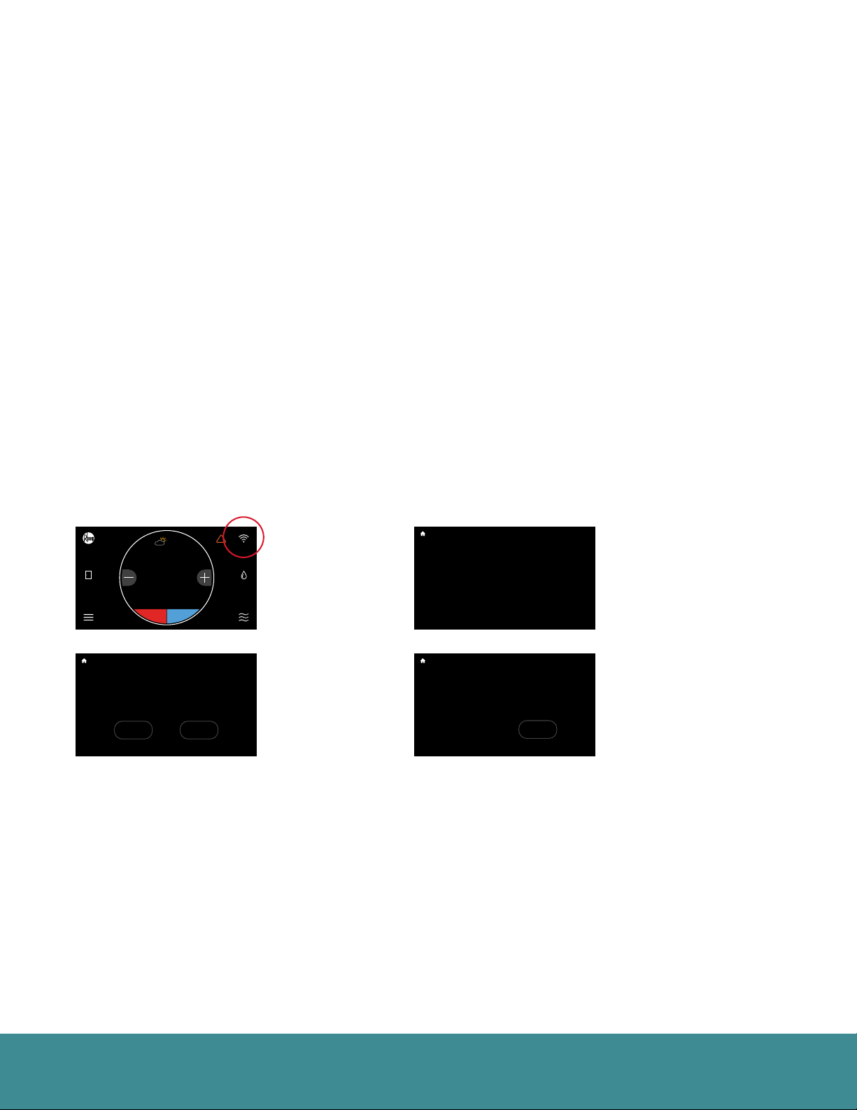
3. On the EcoNet Smart Thermostat, tap the WiFi icon in the top right corner of the home screen (See Fig. 1).
4. Select ‘Get Started’ (See Fig. 2).
5. When ‘Ready to Connect’ appears, use the EcoNet App to complete the setup process (See Fig. 3).
6. Follow the in-app instructions to complete your connection.
7. You may be required to enter your network password.
8. Tap ‘Done’ to complete setup (See Fig. 4).
Basic Settings
Installer Checkout
68
80
80
80
Backlight Enabled?
Outside Temp Selection?
Home 44%
Home
Away
BACK
BACK
Backlight Enabled?
Outside Temp Selection?
Connect to Wi-Fi to receive local weather
and remotely manage your system with the
EcoNet mobile app.
Home 44%
Away
Started
BACK
BACK
Away
Group 1
Resume Schedule
71
36
72
75
71
75
Refrigeration
Cooling to
OFF
62 85
34
85
65
70
Basic Settings
Installer Checkout
Wi-Fi Setup
Away
Group 1
Resume Schedule
71
36
72
75
71
Get
Refrigeration
Cooling to
OFF
34
85
65
70
80
Yes
Internet
68
80
80
80
Yes
Internet
Setup
!
!
Linearize Dampers
Dining Room
Basement
!
Linearize Dampers
Later
Dining Room
Basement
Zone 4
UNITS
Zone 4
UNITS
Zone 3
47%
61%
44%
44%
Zone 3
47%
61%
44%
(Fig. 1)
(Fig. 2)
Basic Settings
Installer Checkout
Almost There!
68
80
80
Backlight Enabled?
Outside Temp Selection?
When "Ready to Connect" appears below use the
EcoNet app to complete the setup process.
Home 44%
Away
BACK
BACK
Backlight Enabled?
Outside Temp Selection?
Congratulations! Your thermostat has successfully been
connected to Wi-Fi.
Home 44%
Away
BACK
BACK
80
Yes
Away
Group 1
Resume Schedule
Internet
71
36
72
75
71
Ready to Connect
Refrigeration
Cooling to
OFF
34
85
65
70
Basic Settings
Installer Checkout
Setup Complete!
68
80
80
80
Yes
Away
Group 1
Resume Schedule
Internet
71
36
72
75
71
Refrigeration
Cooling to
OFF
34
85
65
70
Done
Zone 3
Zone 4
!
Linearize Dampers
47%
61%
44%
Dining Room
UNITS
Basement
WiFi Status
Zone 3
Zone 4
!
Linearize Dampers
47%
61%
44%
Dining Room
UNITS
Basement
(Fig. 3)
(Fig. 4)
EcoNet® Smart Thermostat User Guide 10> Return to Table of Contents
Page 11
Weather
Zoning System Test
T957_O Low Refrigerant Pressure
21
status: Setting airflow
CFM: 840
54
Zoning System Test
T957_O Low Refrigerant Pressure
21
status: Setting airflow
CFM: 840
54
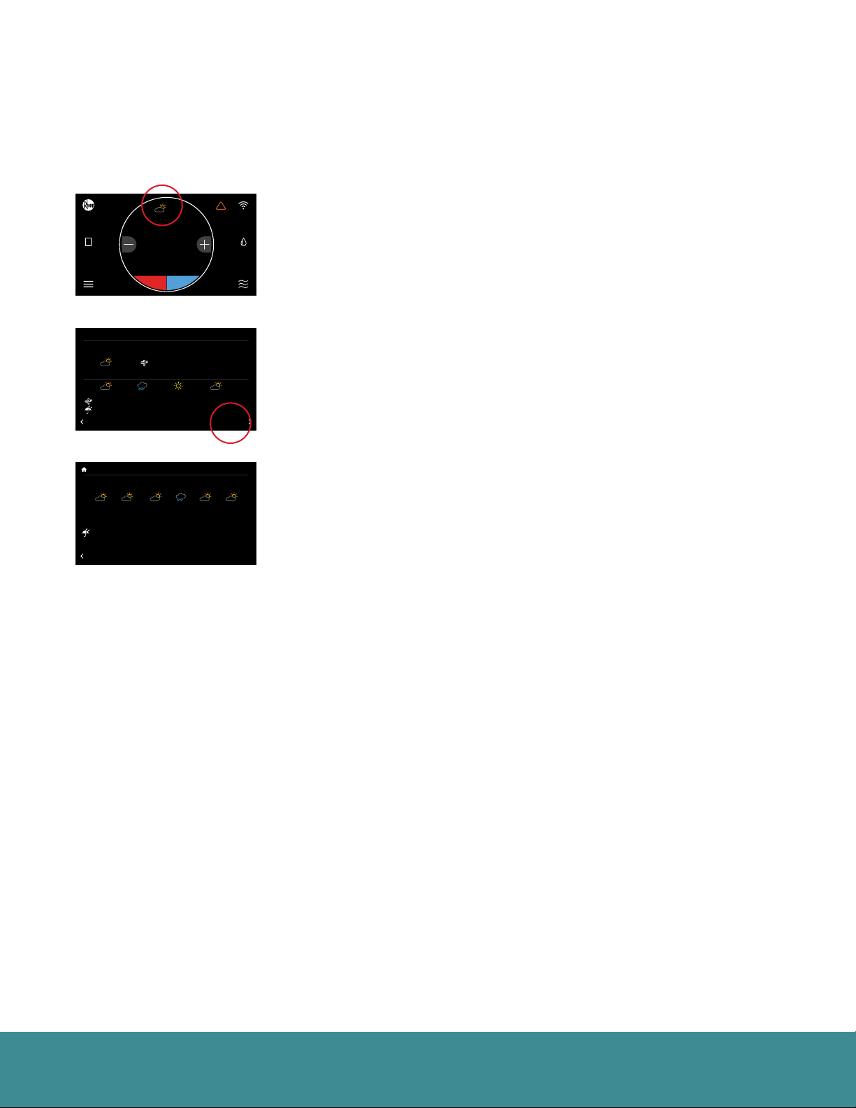
Tap the weather icon on the home screen to display local weather conditions and view the hourly and
daily forecasts. The weather will be based on the current location or ZIP code used when creating your
EcoNet account.
Basic Settings
Installer Checkout
68
80
80
80
Backlight Enabled?
Outside Temp Selection?
Home 44%
Home
Away
BACK
BACK
Backlight Enabled?
Currently: HI: 92 LO: 77
Outside Temp Selection?
BACK
BACK
Backlight Enabled?
TUE WED THU FRI SAT SUN
Outside Temp Selection?
75 80 75 70 7070HI
Home 44%
Away
LO 55 60 55 50 5050
0% 0% 80% 0% 0%0%
BACK
BACK
BACK
80
Yes
Away
Group 1
Resume Schedule
Internet
71
36
72
75
71
75
Refrigeration
Cooling to
OFF
62 85
34
85
65
70
Basic Settings
Today’s Weather
68
80 ºF
Yes
Away
50 %Rh
Internet
5
MPH, N
12 pm 6 pm 12 am6 am
71
75 80 5065
5 , N 0 , N 10 , N5 , N
80% 0% 0%0%
OFF
Basic Settings
Installer Checkout
Forecast
68
80
80
80
Yes
Away
Group 1
Resume Schedule
Internet
71
36
72
75
71
Refrigeration
Cooling to
OFF
34
85
65
70
Zone 4
!
!
Linearize Dampers
Dining Room
UNITS
Basement
Dining Room
FORECAST
Zone 4
!
Linearize Dampers
Dining Room
UNITS
Basement
Zone 3
47%
61%
44%
44%
Zone 3
47%
Zone 3
47%
61%
44%
Current Weather Conditions
24-Hour Forecast
6-Day Forecast
EcoNet® Smart Thermostat User Guide 11> Return to Table of Contents
Page 12
Menu Options
Zoning System Test
T957_O Low Refrigerant Pressure
21
status: Setting airflow
CFM: 840
54
Away
Humidity
Time
Basic
Vacation
Fan
Zoning System Test
T957_O Low Refrigerant Pressure
21
status: Setting airflow
CFM: 840
54
Zoning System Test
T957_O Low Refrigerant Pressure
21
status: Setting airflow
CFM: 840
54
Fahrenheit
2 hours
5 min.
Zoning System Test
T957_O Low Refrigerant Pressure
21
status: Setting airflow
CFM: 840
54
Basic Settings
Installer Checkout
68
80
80
80
Backlight Enabled?
Outside Temp Selection?
Home 44%
Home
Away
BACK
BACK
80
Yes
Away
Group 1
Resume Schedule
Internet
71
36
72
75
71
75
Refrigeration
Cooling to
OFF
62 85
34
85
65
70
!
!
Linearize Dampers
Dining Room
Settings
Basic Settings
Installer Checkout
Menu
68
80
80
Backlight Enabled?
Outside Temp Selection?
Settings
Home 44%
Away
BACK
BACK
BACK
Backlight Enabled?
Outside Temp Selection?
Home 44%
Away
BACK
BACK
BACK
80
Yes
Away
Group 1
Resume Schedule
Internet
Schedule
71
36
72
75
71
Water Heating
Refrigeration
Cooling to
OFF
34
85
65
70
Basic Settings
Installer Checkout
Settings
68
80
80
80
Yes
Away
Group 1
Resume Schedule
Internet
71
36
72
75
71
Refrigeration
Cooling to
OFF
34
85
65
70
Status
!
Linearize Dampers
Service
Dining Room
!
Linearize Dampers
Dining Room
Installer
Zone 3
Zone 4
47%
61%
44%
44%
UNITS
Basement
Zone 3
Zone 4
47%
61%
44%
UNITS
Basement
Zone 3
Zone 4
47%
61%
44%
UNITS
Basement
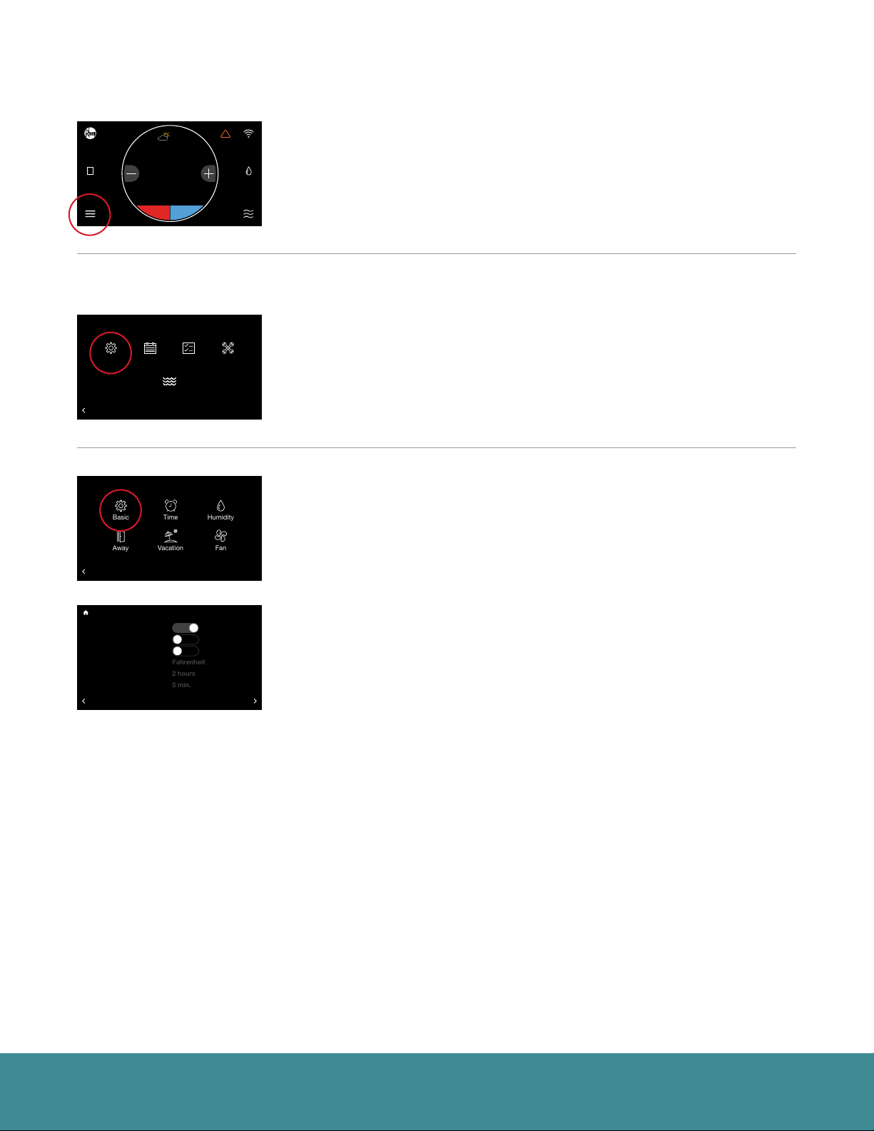
Tap the Menu icon in the bottom left corner of the home screen to easily
view and configure your personal and system settings.
Settings (Menu > Settings)
Adjust system-level settings and preferences, from customizing your away
temperatures to scheduling a vacation. Tap the Menu icon from the home
screen and then tap Settings.
Basic (Menu > Settings > Basic)
Adjust thermostat or basic equipment settings and preferences.
Basic Settings
Installer Checkout
Basic Settings
68
80
80
Backlight Enabled?
Follow Schedule?
Outside Temp Selection?
Alarm Beep Enable?
Screen Lock?
Temperature Display
Home 44%
Away
Schedule Override Time
Auto-Changeover Time
BACK
BACK
BACK
80
Yes
Yes
Away
Group 1
Resume Schedule
Internet
71
36
72
75
71
Refrigeration
Cooling to
OFF
34
85
65
70
No
No
Zone 4
!
Linearize Dampers
Dining Room
UNITS
Basement
MORE
Zone 3
47%
61%
44%
Follow Schedule – If a programmed schedule is desired, set to “Yes.”
Alarm Beep Enable – Sounds an audible alarm tone shall a critical alarm
condition occur.
Screen Lock – To lock the main screen from any changes, enable the lock. To
unlock, enter the Basic settings menu again and set Screen Lock to “No.” This
locking function prevents any changes except changes made from within the
Basic Settings.
Temperature Display – Change your indoor temperature and set points
between Fahrenheit and Celsius.
Schedule Override Time – While a schedule is running, if a set temperature
change occurs on the main screen, the change will be in effect for this amount
of time. The default is 2 hours. You can customize between a minimum
override of 1 hour and a maximum of 8 hours. You can also choose to have the
override in effect until canceled, or until the next scheduled day part.
Auto Changeover Time – When the system is in Auto mode, this is the
amount of time demand must exist in the opposite mode (cooling or heating)
in order for the system to switch to that mode. The default is 5 minutes. The
setting is configurable between 5 and 60 minutes.
EcoNet® Smart Thermostat User Guide 12> Return to Table of Contents
Page 13
Settings (con’t)
Zoning System Test
T957_O Low Refrigerant Pressure
21
status: Setting airflow
CFM: 840
54
2º F
0.0º F
0.0 %
Internal
Basic Settings
Installer Checkout
Basic Settings
68
80
80
Backlight Enabled?
Set Point Deadband
Outside Temp Selection?
Temperature Offset
Relative Humidity Offset
Room Sensor Selection
Home 44%
Away
Proximity Sensing?
Smooth Arrival Enabled?
BACK
BACK
BACK
80
Yes
Away
Group 1
Resume Schedule
Internet
71
36
72
75
71
Yes
Refrigeration
Cooling to
Yes
OFF
34
85
65
70
Zone 4
!
Linearize Dampers
Dining Room
UNITS
Basement
MORE
Zone 3
47%
61%
44%
More >
Set Point Deadband – This is the minimum difference between heating and
cooling set points in Auto mode. The default is 2 degrees. This setting is
configurable between 0 and 6 degrees. A 0 degree deadband means your
system will switch between heating and cooling to maintain the specified set
point. The smaller the deadband setting the more frequently your system will
switch between heating and cooling.
Temperature Offset – This is an offset applied to the displayed room
temperature. A negative offset will cause the displayed indoor temperature to
be less than the sensed temperature. A positive offset will cause the displayed
temperature to be higher than sensed temperature.
Relative Humidity Offset – This is an offset applied to the indoor relative
humidity. A negative offset will cause the displayed relative humidity to be less
than the sensed relative humidity. A positive offset will cause the displayed
relative humidity to be higher than sensed relative humidity.
Note: You should allow the thermostat to calibrate in the conditioned space for 30 minutes before
adjusting offsets.
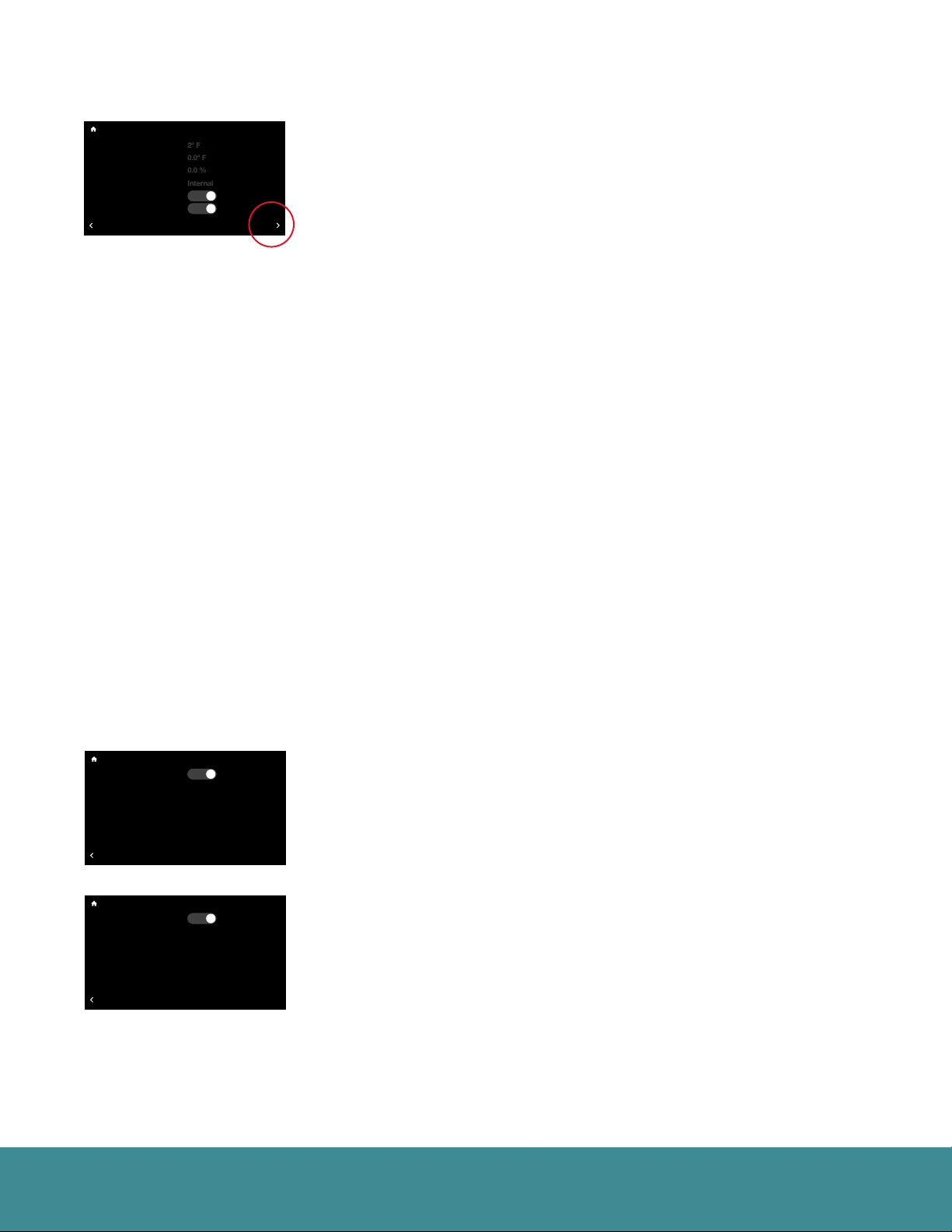
Room Sensor Selection – You can wire a remote 10K temperature sensor* to
the EcoNet Smart Thermostat. If a remote temperature sensor is connected,
you can choose to use the remote sensor, internal sensor on the Smart
Thermostat or an average between the two for current indoor temperature.
Backlight Enabled?
Basic Settings
Outside Temp Selection?
BACK
Basic Settings
Backlight Enabled?
Outside Temp Selection?
BACK
Yes
Internet
Yes
Equipment
*Optimized for use with an Aprilaire 8051 indoor temperature sensor.
Proximity Sensing – Selecting ‘No’ will disable the motion sensor. To activate
the thermostat, you will need to tap the screen.
Smooth Arrival – The thermostat will start recovery at the optimum time
to ensure the set point is reached at the scheduled time. If a setback in
temperature is scheduled, for either cooling or heating, the set temperature
is ramped to the next scheduled set temperature 60 minutes before the next
time period.
Backlight Enabled – When the thermostat is not being used it will enter
standby mode. The default screen brightness in standby is 1%. You can turn
off the Backlight when in standby by selecting “No.”
Outside Temp Selection – The selection determines where the outside
temperature that is displayed on the home screen is pulled from. Choose
between Internet and Equipment.
• Internet – Pulls temperature based on your zip code.
• Equipment – Uses the temperature sensor installed on your
outdoor condenser.
EcoNet® Smart Thermostat User Guide 13> Return to Table of Contents
Page 14
Settings (con’t)
Zoning System Test
T957_O Low Refrigerant Pressure
21
status: Setting airflow
CFM: 840
54
Away
Humidity
Time
Basic
Vacation
Fan
Zoning System Test
T957_O Low Refrigerant Pressure
21
status: Setting airflow
CFM: 840
54
Zoning System Test
T957_O Low Refrigerant Pressure
21
status: Setting airflow
CFM: 840
54
Zoning System Test
T957_O Low Refrigerant Pressure
21
status: Setting airflow
CFM: 840
54
Away
Humidity
Time
Basic
Vacation
Fan
Basic Settings
Installer Checkout
Settings
68
80
80
Backlight Enabled?
Outside Temp Selection?
Home 44%
Away
BACK
BACK
BACK
Backlight Enabled?
Outside Temp Selection?
2 :
Home 44%
Away
Jan
BACK
BACK
BACK
Backlight Enabled?
Outside Temp Selection?
Home 44%
Away
BACK
BACK
BACK
Backlight Enabled?
Enable Dehumidification?
Outside Temp Selection?
Dehumidify Set Point
Over-Cooling Amount
Dehumidify Drain Timer
Home 44%
Away
BACK
BACK
BACK
80
Yes
Away
Group 1
Resume Schedule
Internet
71
36
72
75
71
Refrigeration
Cooling to
OFF
34
85
65
70
Basic Settings
Installer Checkout
Time and Date
68
80
80
80
Yes
Away
Group 1
Resume Schedule
Internet
38
29
71
36
72
75
71
Refrigeration
Cooling to
OFF
Accept
34
85
65
70
Basic Settings
Installer Checkout
Settings
68
80
80
80
Yes
Away
Group 1
Resume Schedule
Internet
71
36
72
75
71
Refrigeration
Cooling to
OFF
34
85
65
70
Basic Settings
Installer Checkout
Dehumidification
68
80
80
80
Yes
Yes
Away
Group 1
Resume Schedule
Internet
52 %
0 ºF
5 min.
71
36
72
75
71
Refrigeration
Cooling to
OFF
34
85
65
70
Zone 4
!
Linearize Dampers
Dining Room
UNITS
Basement
Installer
Zone 4
!
Linearize Dampers
pm
2018
D.S.T.
Yes
Dining Room
UNITS
Basement
Zone 4
!
Linearize Dampers
Dining Room
UNITS
Basement
Installer
Zone 4
!
Linearize Dampers
Dining Room
UNITS
Basement
HUMIDIFICATION
Zone 3
47%
61%
44%
Zone 3
47%
61%
44%
Zone 3
47%
61%
44%
Zone 3
47%
61%
44%
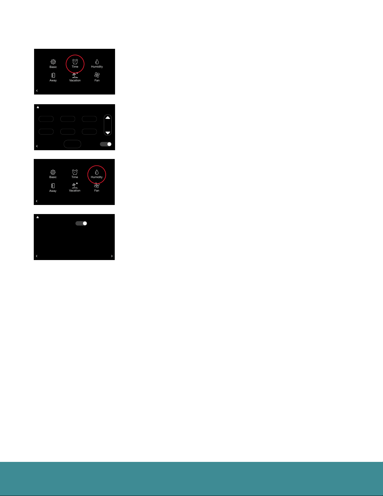
Time & Date (Menu > Settings > Time)
Set the current time and date. Your schedule times, vacation events and
weather forecast will be based off the time entered on this screen. It is
important to ensure the correct date and time are programmed before
setting your schedule.
DST – At the bottom of this screen you can elect to enable or disable
daylight savings time.
Humidity Settings (Menu > Settings > Humidity)
Control your home’s humidity settings for more ideal comfort.
Dehumidification (Menu > Settings > Humidity)
Enable Dehumidification – The system will attempt to reduce humidity
in cooling mode by reducing fan speed and over-cooling the space (when
allowed by the Over-Cooling setting). The system will only reduce airflow if
the room temperature is within one degree of set point, otherwise, full cooling
airflow will be performed.
Dehumidify Set Point – The indoor relative humidity to be controlled to while
in cooling mode.
Over-Cooling Amount – The system will activate cooling, and possibly overcool the space by the desired number of degrees to improve dehumidification
performance in an effort to reach the dehumidify set point. The factory setting
for over-cooling is zero (no over-cooling) and can be adjusted up to 5 degrees
of over-cooling.
Dehumidify Drain Timer – At the end of a cooling cycle, if set, the continuous
fan setting will be turned off for the selected amount of time in order to drain
water from the indoor coil.
EcoNet® Smart Thermostat User Guide 14> Return to Table of Contents
Page 15
Settings (con’t)
Zoning System Test
T957_O Low Refrigerant Pressure
21
status: Setting airflow
CFM: 840
54
30 %
Heat
Off
Off
Zoning System Test
T957_O Low Refrigerant Pressure
21
status: Setting airflow
CFM: 840
54
30 %
Heat
Off
Off
Zoning System Test
T957_O Low Refrigerant Pressure
21
status: Setting airflow
CFM: 840
54
Away
Humidity
Time
Basic
Vacation
Fan
Basic Settings
Installer Checkout
Humidification
68
80
80
Backlight Enabled?
Enable Humidification?
Outside Temp Selection?
Humidify Set Point
Humidify During...
Smart Control
Home 44%
Away
Humidity With Fan
BACK
BACK
BACK
Backlight Enabled?
Enable Humidification?
Outside Temp Selection?
Humidify Set Point
Humidify During...
Smart Control
Home 44%
Away
Humidity With Fan
BACK
BACK
BACK
80
Yes
Away
Group 1
Resume Schedule
Internet
71
36
72
75
71
Refrigeration
Cooling to
OFF
34
85
65
70
Basic Settings
Installer Checkout
Humidification
68
80
80
80
Yes
Away
Group 1
Resume Schedule
Internet
71
36
72
75
71
Refrigeration
Cooling to
OFF
34
85
65
70
No
No
Zone 4
!
Linearize Dampers
Dining Room
UNITS
Basement
Zone 4
!
Linearize Dampers
Dining Room
UNITS
Basement
Zone 3
47%
61%
44%
Zone 3
47%
61%
44%
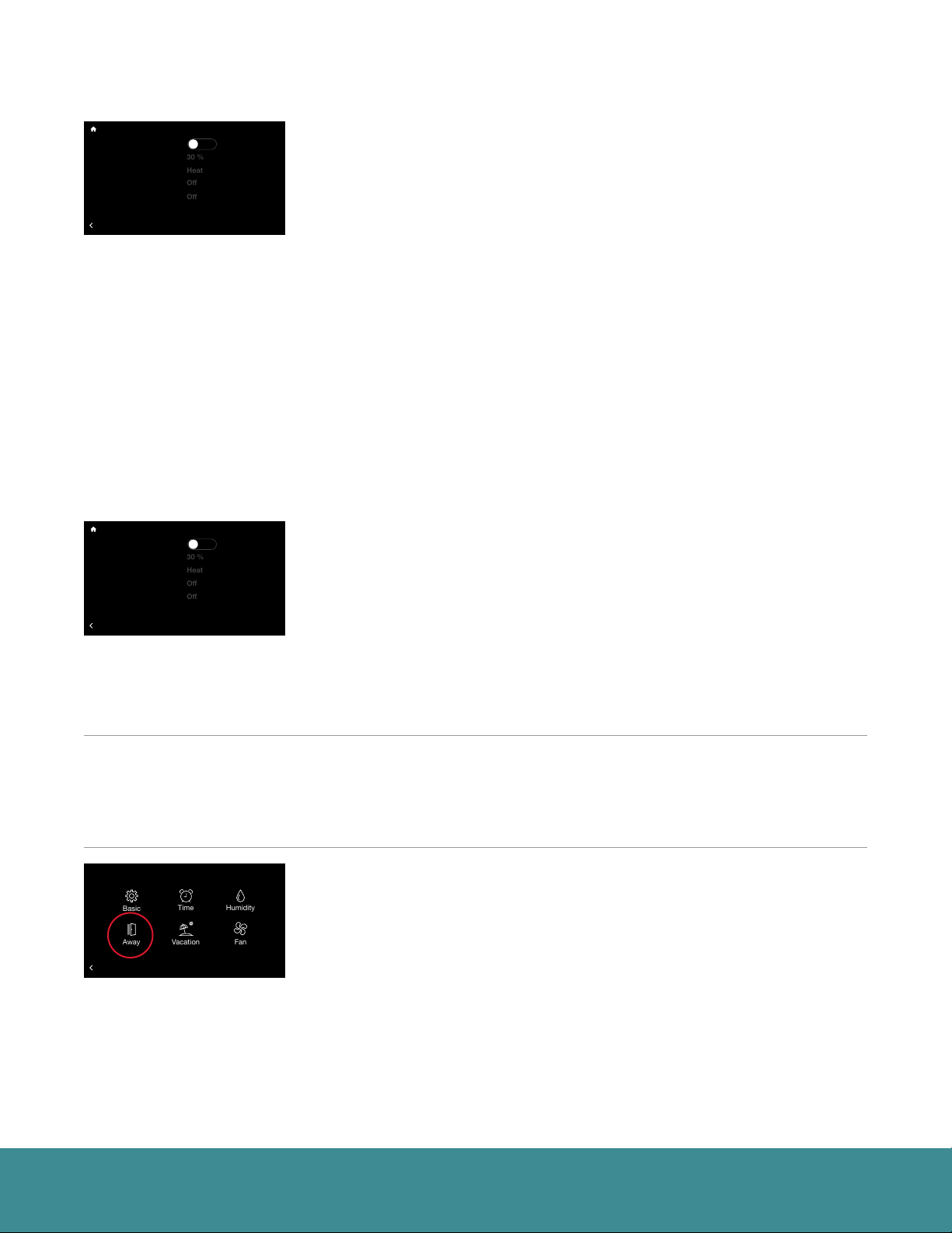
Humidification (Menu > Settings > Humidity > Humidification)
Enable Humidification – The system can control a humidifier attached to the
furnace or air handler to increase humidity in the space. It is important to note
you cannot humidify above the dehumidification set point.
Humidification Set Point – This setting allows you to choose the indoor
relative humidity desired, under which humidification will activate. The default
is humidification set point is 30% and is configurable between 15 and 45%.
Humidify During – Select the modes in which humidification will be
performed. Humidification can occur during heating, continuous fan and/or
cooling mode.
• Heat – Humidifier will operate with equipment during Heat if a humidification
demand is present.
• Heat/Fan – Humidifier will operate with equipment during these modes if a
humidification demand is present.
• Heat/Fan/Cool – Humidifier will operate with equipment during these modes
if a humidification demand is present.
Smart Control – Smart Control is used to reduce or prevent water
condensation on the inside of windows while humidifying in the winter season.
The control monitors indoor and outdoor temperatures and reduces the
humidification percentage according to the Smart Control level chosen by the
user. Start out with the Low setting. If objectionable condensation occurs on
windows, choose the Medium or High setting.
Humidify With Fan – If there is a call to humidify and the fan and heating/
cooling are off, the fan will be forced on to humidify. Select the desired fan
speed from Low to High.
Note: Humidification is only available if a humidifier is installed.
How to Test a Humidifier
Adjust the humidify set point up to ‘TEST’, select Humidify during “Heat/Fan”, then turn on a continuous fan
speed on the Fan screen under Settings. This should force the humidifier to run. This setting will last for 30
minutes, where the maximum setting will return to 4% below the dehumidification set point.
Basic Settings
Installer Checkout
Settings
68
80
80
Backlight Enabled?
Outside Temp Selection?
Home 44%
Away
BACK
BACK
BACK
80
Yes
Away
Group 1
Resume Schedule
Internet
71
36
72
75
71
Refrigeration
Cooling to
OFF
34
85
65
70
Zone 3
Zone 4
!
Linearize Dampers
47%
61%
44%
Dining Room
UNITS
Basement
Installer
Away Settings (Menu > Settings > Away)
Your system will follow the customized heating, cooling and fan settings when
you place your system into ‘Away’ mode. The system can be placed into
Away by selecting the Home icon (closed door) on the home screen. Once
the system is placed into Away mode it will remain until canceled. Simply tap
the Away icon (open door) to exit Away mode. The system will resume the
schedule or return to the previous settings if a schedule is not being followed.
You can also exit Away by increasing or decreasing the temperature.
Note: If your system is in Cool or Heat when placed into Away mode your system will only manage
to the respective Away set point.
EcoNet® Smart Thermostat User Guide 15> Return to Table of Contents
Page 16
Settings (con’t)
Zoning System Test
T957_O Low Refrigerant Pressure
21
status: Setting airflow
CFM: 840
54
Away
Humidity
Time
Basic
Vacation
Fan
Zoning System Test
T957_O Low Refrigerant Pressure
21
status: Setting airflow
CFM: 840
54
Zoning System Test
T957_O Low Refrigerant Pressure
21
status: Setting airflow
CFM: 840
54
Zoning System Test
T957_O Low Refrigerant Pressure
21
status: Setting airflow
CFM: 840
54
Away
Humidity
Time
Basic
Vacation
Fan
68
Away
71
OFF
Basic Settings
Installer Checkout
Settings
68
80
80
Backlight Enabled?
Outside Temp Selection?
Home 44%
Away
BACK
BACK
BACK
80
Yes
Away
Group 1
Resume Schedule
Internet
71
36
72
75
71
Refrigeration
Cooling to
OFF
34
85
65
70
Dining Room
Zone 4
!
Linearize Dampers
Dining Room
UNITS
Basement
Installer
Zone 3
47%
Zone 3
47%
61%
44%
If you have an EcoNet Zoning System and the EcoNet Zone Control ‘Away’
heat set point is set to 50°F (10°C) or the cool set point is set to 92°F (33°C),
the Zone Control will default to Off. Adjusting the ‘Away’ heat set point as low
as 51°F (11°C) and the cool set point up to 91° (32°C) will allow the zone to be
conditioned when required.
Configure individual ‘Away’ settings for each zone from the EcoNet Zone Control
or through the EcoNet App. From the respective Zone Control unit, tap Menu >
Away to configure the unique ‘Away’ set point for a particular zone.
Refer to pg.17 to enable your Zoning System.
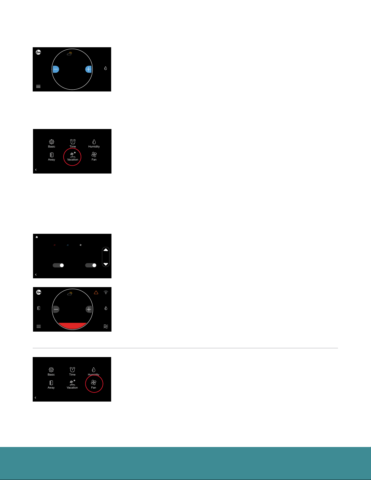
Vacation (Menu > Settings > Vacation)
The Vacation screen allows you to preschedule desired heating, cooling and
fan settings when you are going to be away for an extended time.
To schedule your vacation, select the time, month, day and year and then use
the up and down arrows to set desired start and end dates.
Note: You will need to set the vacation end time and date before you can set its start.
If you have an EcoNet Zoning System each zone will follow the configured
‘Away’ settings during ‘Vacation’ events. To customize the Away / Vacation
settings from the Zone Control unit, tap Menu > Away. This will allow you to set
unique ‘Vacation’ setting for a particular zone. Refer to pg.17 to enable your
Zoning System.
Basic Settings
Installer Checkout
Vacation Settings
68
80
80
Backlight Enabled?
Outside Temp Selection?
02:00 pm Jan. 29 2018
Start:
Home 44%
Away
End:
02:30 pm Feb.102018
Vacation
Yes
BACK
BACK
BACK
Backlight Enabled?
Outside Temp Selection?
Home 44%
Away
BACK
BACK
Backlight Enabled?
Outside Temp Selection?
Home 44%
Away
BACK
BACK
BACK
80
Yes
85º
Away
Group 1
Resume Schedule
Internet
71
36
72
75
71
Water
Refrigeration
Cooling to
Heater
OFF
34
85
65
70
Basic Settings
Installer Checkout
68
80
80
80
80
Yes
Away
Group 1
Resume Schedule
Vacation
Internet
71
36
72
75
71
77
Refrigeration
Cooling to
OFF
64
34
85
65
70
Basic Settings
Installer Checkout
Settings
68
80
80
80
Yes
Away
Group 1
Resume Schedule
Internet
71
36
72
75
71
Refrigeration
Cooling to
OFF
34
85
65
70
Auto65º
Zone 4
!
Linearize Dampers
Yes
Dining Room
UNITS
Basement
Zone 4
!
!
Linearize Dampers
Dining Room
UNITS
Basement
Zone 4
!
Linearize Dampers
Dining Room
UNITS
Basement
Installer
Zone 3
47%
61%
44%
Zone 3
47%
61%
44%
36%Away
Zone 3
47%
61%
44%
Select each set point and fan speed and then use the up down arrows to set
to your desired vacation conditions. We recommend setting the fan speed
to Auto.
Vacation Activated – A Vacation will be indicated by the word ‘Vacation’
above the current temperature on the home screen and an active Away button.
Tap Vacation on the home screen to cancel and resume schedule or return to
previous settings.
Your HVAC equipment will automatically follow a vacation event. If you have a
connected water heater, you have the option to have your water heater follow
the vacation event; simply toggle the button to Yes.
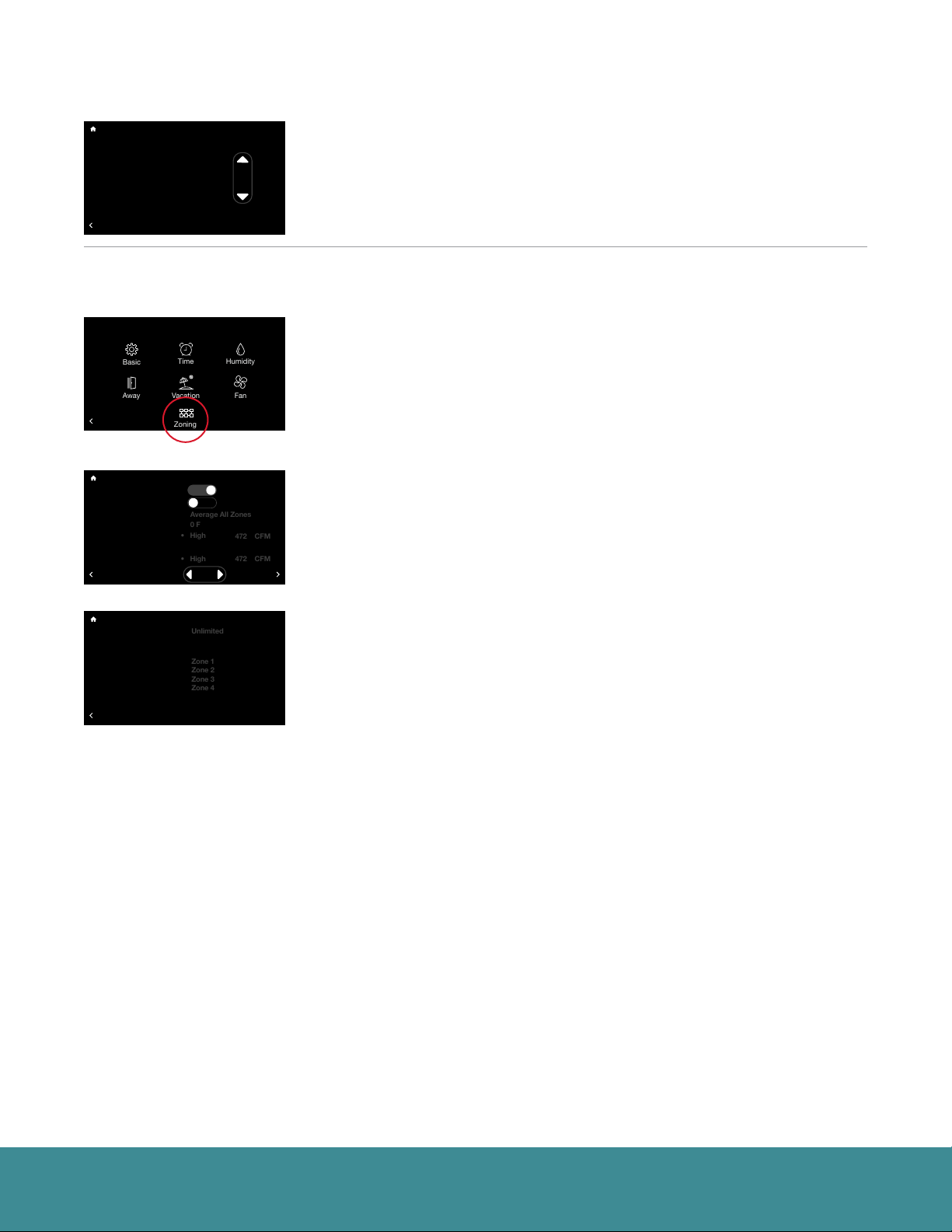
Fan (Menu > Settings > Fan)
Fan Speed – Chose from one of 5 speeds to run continuous fan. This
setting allows the fan to continue circulating air in between calls for heating
or cooling. If the system is following a schedule the fan speed presented
will match the speed set in your schedule. You can temporarily override the
scheduled fan speed here. You will notice the copy on screen changes to
‘Fan Speed Override’. The override will follow the ‘Schedule Override Time’
set in Basic Settings.
EcoNet® Smart Thermostat User Guide 16> Return to Table of Contents
Page 17
Settings (con’t)
Unlimited
Zone 1
Zone 2
Zone 3
Zone 4
Average All Zones
0 F
• High
• High
472 CFM
472 CFM
Away
Humidity
Time
Basic
Vacation
Zoning
Fan
Fan Setting
Fan Mode – This feature allows you to define the minimum amount of time
each hour that the system fan will run. The default is continuous and the fan
Fan Speed: Auto
Fan Mode: Timed, 20 min.
will run in between heating and cooling calls constantly. You can adjust the
minimum fan runtime between 10 and 40 minutes per hour. The fan runtime
applies during any mode selected except when the system is turned off.
BACK
Note: When fan speed is set to Auto the Fan Mode setting is not applicable.
If you have an EcoNet Zoning System, see below:
Please refer to the EcoNet Zoning I/O manual for proper installation instructions.
Backlight Enabled?
Outside Temp Selection?
BACK
BACK
Zoning Enabled?
Backlight Enabled?
All Zones Follow Zone 1?
Outside Temp Selection?
Humidity Sensor to Use
Over-Conditioning
Zone 1 Airflow Setting
Zone 2 Airflow Setting
Zone 3 Airflow Setting
BACK
BACK
Basic Settings
71
36
72
Basic Settings
Zoning Settings
71
36
72
Settings
68
80
Yes
Away
Group 1
Internet
Refrigeration
OFF
34
85
68
80
Yes
Yes
Away
Group 1
Internet
• High
Refrigeration
OFF
34
85
No
!
Dining Room
Basement
Installer
!
472 CFM
Dining Room
Basement
MORE
Zone 4
UNITS
Zone 4
UNITS
Zone 3
47%
61%
Zone 3
47%
61%
Zoning (Menu > Settings > Zoning)
If a zoning application is installed tap Menu > Settings. Tap the Zoning icon
to view Zoning Settings.
Note: System level Zone Settings are only accessible through the EcoNet Smart Thermostat and
not through the EcoNet Zone Controls. Temperature changes to individual zones can be made
from the Smart Thermostat under Menu > Zoning, via the individual zone controls or through the
EcoNet App2.
On the Zoning Settings menu, set Zoning Enabled to ‘Yes’ to display
applicable zone settings. From this screen you can select which zone
you want to use to track relative humidity, customize airflow noise limits
and name zones.
Basic Settings
Zone 4 Airflow Setting
Backlight Enabled?
Outside Temp Selection?
Zone 1 Name Text
Zone 2 Name Text
Zone 3 Name Text
Zone 4 Name Text
BACK
BACK
Zoning Settings
71
36
72
68
80
Yes
Away
Group 1
Internet
Refrigeration
OFF
34
85
!
Dining Room
Basement
Zone 4
UNITS
Zone 3
47%
61%
All Zones Follow Zone 1 – Default is set to ‘No’. Selecting ‘Yes’ will ensure
all additional zones will follow the mode, set points and fan speed you have
selected for Zone 1.
Humidity Sensor to Use – Default is Zone 1. However, you can select to
follow the humidity reading from any individual zone or chose to follow the
average humidity reading from all zones.
Over Conditioning – This is a setting that can allow Zone 1 to be conditioned
below the set point in order to allow the system to continue to condition
a calling zone that is not large enough to run the equipment by itself. The
default is set to Auto. Auto will allow the system to over-condition Zone 1 up
to the most conditioned zone set point. You can also choose to restrict OverConditioning in Zone 1 by setting to ‘None’ or setting to a specific degree
between 1-10°F.
The individual zone Over-Conditioning settings may be adjusted directly from
the respective zone control.
Zone Airflow Setting – Adjust airflow noise level limits for each zone.
The system will automatically set the airflow limit for each zone to one level
above the minimum airflow required to run the system.
We recommended leaving the airflow setting at the level and CFM assigned by
the system. If the airflow in a given zone is too loud, return to this screen and
set a lower limit.
Note: It is important to keep in mind that if only one zone calls, its maximum airflow setting must
be greater than the minimum airflow required by the system or the equipment will not operate.
For the system to operate in this scenario, at least one zone must be set to over-condition. This
condition will be represented by an asterisk next to the airflow limit.
Zone Name – Customize the name for each zone using the on-screen keyboard.
EcoNet® Smart Thermostat User Guide 17> Return to Table of Contents
Page 18
Zoning System Test
T957_O Low Refrigerant Pressure
21
status: Setting airflow
CFM: 840
54
Zoning System Test
T957_O Low Refrigerant Pressure
21
status: Setting airflow
CFM: 840
54
Zoning System Test
T957_O Low Refrigerant Pressure
21
status: Setting airflow
CFM: 840
54
Schedules
Zoning System Test
T957_O Low Refrigerant Pressure
21
status: Setting airflow
CFM: 840
54
Basic Settings
Installer Checkout
Menu
68
80
80
Backlight Enabled?
Outside Temp Selection?
Settings
Home 44%
Away
BACK
BACK
BACK
T
M
Backlight Enabled?
Outside Temp Selection?
Morning
05:30 am Auto
Day 07:00 am Auto
Away
Evening 07:30 pm Auto
Night 10:30 pm Auto
Copy Day Cancel
BACK
BACK
BACK
T
M
Backlight Enabled?
Outside Temp Selection?
Morning
05:30 am Auto
Day 07:00 am Auto
Away
Evening 07:30 pm Auto
Night 10:30 pm Auto
Copy Day Cancel Paste Day
BACK
BACK
BACK
Away
Group 1
Resume Schedule
Schedule
71
36
72
75
71
Water Heating
Refrigeration
Cooling to
OFF
34
85
65
70
Basic Settings
Installer Checkout
Schedule
T
W
Away
Group 1
Resume Schedule
71
36
72
75
Refrigeration
OFF
34
85
65
Basic Settings
Installer Checkout
Schedule
T
W
Away
Group 1
Resume Schedule
71
36
72
75
Refrigeration
OFF
34
85
65
80
Yes
Internet
Status
68
80
80
F
Yes
Internet
68
80
80
F
Yes
Internet
70º
62º
70º
62º
70º
62º
70º
62º
Zone 4
!
Linearize Dampers
Service
Dining Room
UNITS
Basement
Zone 4
!
S
S
Linearize Dampers
78º
85º
78º
78º
Dining Room
UNITS
Basement
Zone 4
!
S
S
Linearize Dampers
78º
85º
78º
78º
Dining Room
UNITS
Basement
Zone 3
47%
61%
44%
Zone 3
47%
61%
44%
Zone 3
47%
61%
44%
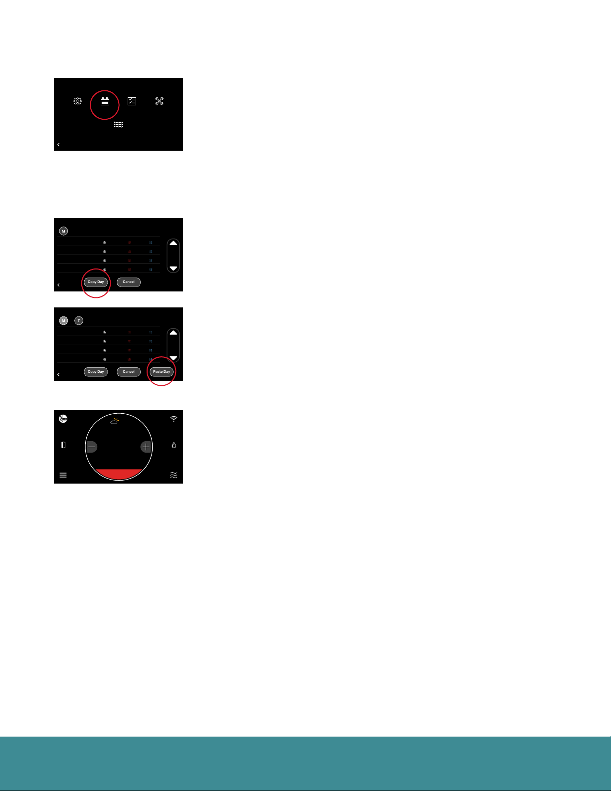
Tapping Menu > Schedule will present your current schedule. First, please
ensure the correct date and time settings have been entered under Settings.
To edit the schedule for a day, tap the day of the week you want to edit. Tap
the day part (morning, day, evening or night) time and use the up and down
arrows to set the desired start time. Next tap the heat set point, cool set
point and/or fan speed for each day part and use the up and down arrows
to change to your desired settings. Your system will follow your preferred
settings until the next day part start time is reached. If Smooth Arrival is
enabled under Basic Settings, your system will start recovery up to 60
minutes early to ensure the set points for the next scheduled day part are
reached at the scheduled time.
To copy a day’s schedule to another day, tap “Copy Day”, then select the
day(s) you wish to copy to, then tap “Paste Day.” You can select “Cancel” to
cancel the paste day operation.
Basic Settings
Backlight Enabled?
Outside Temp Selection?
Away
BACK
BACK
Installer Checkout
Resume Schedule
71
36
72
75
68
80
80
Yes
Away
Group 1
Internet
Refrigeration
OFF
34
85
65
Zone 3
Zone 4
!
Linearize Dampers
47%
61%
44%
Dining Room
UNITS
Basement
When a schedule is being followed and a manual adjustment is made
overriding the schedule, a Resume Schedule option will be displayed above
the current temperature on the home screen. The schedule will be temporarily
overridden according to the schedule override time under Basic Settings. The
default schedule override time is two hours. Your schedule will automatically
resume once the override expires. You can also resume the schedule by
tapping ‘Resume Schedule’ on the home screen.
If you have an EcoNet Zoning System you can set a unique schedule for each
Zone by tapping Menu > Schedule from each respective Zone Control unit.
EcoNet® Smart Thermostat User Guide 18> Return to Table of Contents
Page 19
Status
Zoning System Test
T957_O Low Refrigerant Pressure
21
status: Setting airflow
CFM: 840
54
Zoning System Test
T957_O Low Refrigerant Pressure
21
status: Setting airflow
CFM: 840
54
Zoning System Test
T957_O Low Refrigerant Pressure
21
status: Setting airflow
CFM: 840
54
Zoning System Test
T957_O Low Refrigerant Pressure
21
status: Setting airflow
CFM: 840
54
Zoning System Test
T957_O Low Refrigerant Pressure
21
status: Setting airflow
CFM: 840
54
Basic Settings
Installer Checkout
Menu
68
80
80
Backlight Enabled?
Outside Temp Selection?
Settings
Home 44%
Away
BACK
BACK
BACK
Furnace AC/HP Air Handler
Inside Temp : 77º Outside Temp : 80º
Inside Rel. Humidity : 39%
Thermostat Mode : Off
Equipment Operating Status : Off
BACK
Backlight Enabled?
Current -> Capacity : CFM :0% 0
Temperatures ->
Outside Temp Selection?
Discrete Inputs ->
Static Presure :
Home 44%
Away
Two Week Cycles :
Two Week Hours :
Lifetime Cycles :
Lifetime Hours :
BACK
BACK
BACK
Backlight Enabled?
Unit Type : var-speed 2 tons
Outside Temp:
Outside Temp Selection?
Hold-off Timer:
Two Week Cycles :
Home 44%
Away
Two Week Hours :
Lifetime Cycles :
Lifetime Hours :
BACK
BACK
BACK
80
Yes
Away
Group 1
Resume Schedule
Internet
Schedule
Outside :
0.00 in.
Lo Heat Hi Heat Blower Powered
0
0
0
0
Lo cool Hi cool
1
0
2
0
Status
71
36
72
75
71
Water Heating
Refrigeration
Cooling to
OFF
34
85
65
70
Status
Basic Settings
Installer Checkout
Furnace Status
68
80
80
80
Yes
Away
Group 1
Resume Schedule
G : Aux 1 : Aux 2 :
71
36
72
75
71
Installer Checkout
AC
Resume Schedule
68°
0 Utility Input : Disabled
71
36
72
75
71
Supply :
Internet
off
0
0
0
Refrigeration
Cooling to
0
OFF
34
85
65
70
Basic Settings
AC/HP Status
68
80
80
80
Yes
Away
Group 1
Internet
1
0
6
Refrigeration
Cooling to
2
OFF
34
85
65
70
0 º80º
0
0
0
0
Zone 4
!
Linearize Dampers
Service
Dining Room
UNITS
Basement
ENERGY
Zone 4
!
0
RPM :
Linearize Dampers
Return :
0 º
offoff
0
n/a
0
0 days
Dining Room
UNITS
Basement
Zone 4
!
Linearize Dampers
Dining Room
UNITS
Basement
MORE
Zone 3
47%
61%
44%
Zone 3
47%
61%
44%
Zone 3
47%
61%
44%
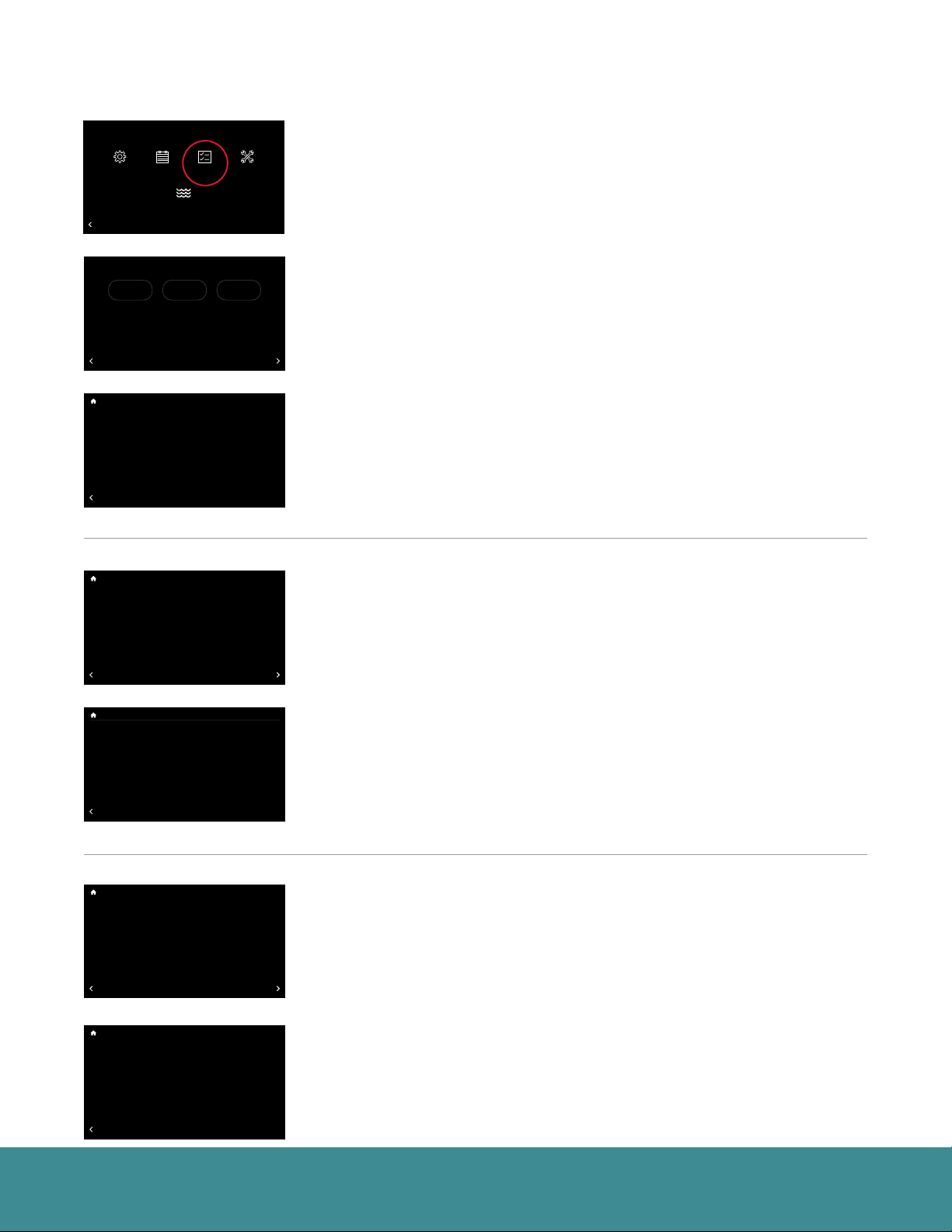
Tapping Menu > Status will display the connected communicating
equipment, thermostat mode and the equipment operating status.
Selecting Furnace, Air Handler or AC/HP on the Status screen will display
each piece of equipment’s current operating status and historical cycles and
run times.
Furnace Status (Menu > Status > Furnace)
Furnace Status – Displays detailed furnace operation information including
two week and lifetime cycles, as well as run time hours.
AC/HP Status (Menu > Status > AC/HP)
AC/HP Status – Displays detailed AC/HP operation information including two
week and lifetime cycles, as well as run time hours.
AC/HP Status
Inverter Current Speed:
EXV Current Position:
Superheat:
Coil Temp:
Suction Line Temp:
Suction Pressure: 203.6 PSIG
Liquid Line Temp:
Liquid Pressure:
Subcooling:
BACK
Basic Settings
Installer Checkout
Backlight Enabled?
Current -> Elec. Heat : CFM :off 0
Temperatures ->
Outside Temp Selection?
Discrete Inputs ->
Static Presure :
Home 44%
Away
Two Week Cycles :
Two Week Hours :
Lifetime Cycles :
Lifetime Hours :
BACK
BACK
BACK
Backlight Enabled?
Outside Temp Selection?
Home 44%
Away
BACK
BACK
BACK
Air Handler Status
Resume Schedule
off
G : Aux 1 : Aux 2 :
0.00 in.
Lo Heat Hi Heat Blower Powered
0
71
36
72
75
71
0
3
Refrigeration
0
Basic Settings
Installer Checkout
Air Handler Status
EXV Current Position ………… 58.2%
Resume Schedule
EXV Current Superheat ……… 10.1°
Suction Line Temp …… ………61.1°
Saturated Suction Temp ……… 51°
Suction Pressure …… …………145 PSIG
71
36
72
75
71
Refrigeration
68
80
80
80
Yes
Away
Group 1
Supply :
Internet
0
0
3
Cooling to
6
OFF
34
85
65
70
68
80
80
80
Yes
Away
Group 1
Internet
Cooling to
OFF
34
85
65
70
0 RPM (0%)
96.0%
---
71.6 º
71.4 º
-40.0º
0.0 PSIG
0.0 º
RPM :
Linearize Dampers
Return :
--
20
4
0
n/a
112
20
115
85 days
Linearize Dampers
!
0
-offoff
Dining Room
Basement
MORE
!
Dining Room
Basement
Zone 4
UNITS
Zone 4
UNITS
Zone 3
47%
61%
44%
Zone 3
47%
61%
44%
Air Handler Status (Menu > Status > Air Handler)
Air Handler Status – Displays detailed air handler operation information
including two week and lifetime cycles, as well as run time hours.
EcoNet® Smart Thermostat User Guide 19> Return to Table of Contents
Page 20

Status (con’t)
If you have an EcoNet Zoning System, see below:
Basic Settings
Status
68
Backlight Enabled?
Air
Outside Temp Selection?
Handler
Inside Temp : 69º Outside Temp : 71º
Inside Rel. Humidity : 56%
Thermostat Mode : Filter Check
Equipment Operating Status : Filter Check
BACK
BACK
Backlight Enabled?
Zone Ht Cl Act %RH %Open CFM
Zone 1
Outside Temp Selection?
Zone 2
Zone 3
Zone 4
80
Yes
Away
Group 1
AC/HP Zoning
Internet
71
36
72
Refrigeration
OFF
34
85
Basic Settings
Zoning Status
68
Yes
Away
65
69
72
Internet
60
85
75
60
85
77
63
70
72
!
49
100
52
0
54
0
50
100
71
BACK
BACK
BACK
OFF
Zone 3
Zone 4
47%
61%
Dining Room
UNITS
Basement
Zone 3
250
0
0
225
47%
Dining Room
Zoning Status (Menu > Status > Zoning)
The Zoning Status displays the current state of every zone showing set point,
current temperature, relative humidity, damper position and airflow CFM.
Note: Set point and fan speed adjustments must be made at the respective Zone Control or
through the EcoNet App2.
EcoNet® Smart Thermostat User Guide 20> Return to Table of Contents
Page 21
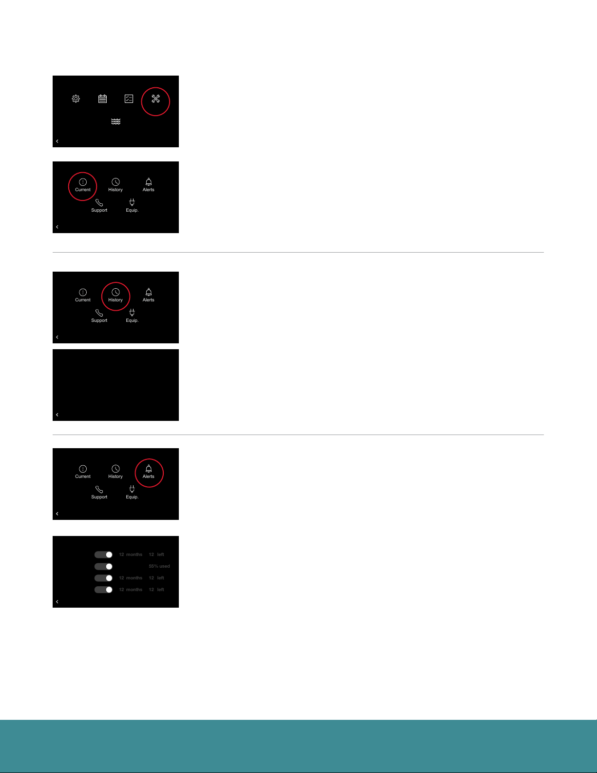
Service
Zoning System Test
T957_O Low Refrigerant Pressure
21
status: Setting airflow
CFM: 840
54
History
Alerts
Equip.
Support
Current
Zoning System Test
T957_O Low Refrigerant Pressure
21
status: Setting airflow
CFM: 840
54
Zoning System Test
T957_O Low Refrigerant Pressure
21
status: Setting airflow
CFM: 840
54
Zoning System Test
T957_O Low Refrigerant Pressure
21
status: Setting airflow
CFM: 840
54
12 left
55% used
12 left
12 left
12 months
12 months
12 months
Zoning System Test
T957_O Low Refrigerant Pressure
21
status: Setting airflow
CFM: 840
54
History
Alerts
Equip.
Support
Current
Zoning System Test
T957_O Low Refrigerant Pressure
21
status: Setting airflow
CFM: 840
54
History
Alerts
Equip.
Support
Current
Basic Settings
Installer Checkout
Menu
68
80
80
Backlight Enabled?
Outside Temp Selection?
Settings
Home 44%
Away
BACK
BACK
BACK
Backlight Enabled?
Outside Temp Selection?
Home 44%
Away
BACK
BACK
BACK
Backlight Enabled?
Outside Temp Selection?
Home 44%
Away
BACK
BACK
BACK
14:47:01 01/29/18
Backlight Enabled?
A021_A Restricted airflow detected. Possible frozen coil
Outside Temp Selection?
20:33:40 02/02/18
A929_O 240V Missing or Inverter Comm Failure 16
Home 44%
Away
BACK
BACK
BACK
80
Yes
Away
Group 1
Resume Schedule
Internet
Schedule
71
36
72
75
71
Water Heating
Refrigeration
Cooling to
OFF
34
85
65
70
Basic Settings
Installer Checkout
Service
68
80
80
80
Yes
Away
Group 1
Resume Schedule
Internet
71
36
72
75
71
Refrigeration
Cooling to
OFF
34
85
65
70
Basic Settings
Installer Checkout
Service
68
80
80
80
Yes
Away
Group 1
Resume Schedule
Internet
71
36
72
75
71
Refrigeration
Cooling to
OFF
34
85
65
70
Basic Settings
Installer Checkout
Alarm History
68
80
80
80
Yes
Away
Group 1
Resume Schedule
Internet
71
36
72
75
71
Refrigeration
Cooling to
OFF
34
85
65
70
Status
Zone 4
!
Linearize Dampers
Service
Dining Room
UNITS
Basement
Zone 4
!
Linearize Dampers
Dining Room
UNITS
Basement
Zone 4
!
Linearize Dampers
Dining Room
UNITS
Basement
Zone 4
!
Linearize Dampers
Dining Room
UNITS
Basement
Clear History
Zone 3
47%
61%
44%
Zone 3
47%
61%
44%
Zone 3
47%
61%
44%
Zone 3
47%
61%
44%
Selecting Menu > Service from the home screen will display current alarms,
alarm history, service alerts, contact info and equipment info.
Current Service (Menu > Service > Current)
Current – Shows any alerts or alarms that are currently active. When an
equipment alert/alarm is present, an alert/alarm icon will appear in the upper
right corner of the home screen, and the alarm beep will sound if enabled.
Select the alert/alarm icon on the home screen to quickly view the alert/alarm
and a brief description.
History (Menu > Service > History)
History – Shows a list of the past eight alerts/alarms with the time and
date stamp.
Basic Settings
Installer Checkout
Service
68
80
80
Backlight Enabled?
Outside Temp Selection?
Home 44%
Away
BACK
BACK
BACK
Backlight Enabled?
Service Call
Outside Temp Selection?
Air Filter
Home 44%
Away
Humidifier Pad
UV Lights
BACK
BACK
BACK
80
Yes
Away
Group 1
Resume Schedule
Internet
71
36
72
75
71
Refrigeration
Cooling to
OFF
34
85
65
70
Basic Settings
Installer Checkout
Service Alerts
68
80
80
80
Yes
Yes
Away
Group 1
Resume Schedule
Internet
Yes
Yes
71
36
72
75
71
Yes
Refrigeration
Cooling to
OFF
34
85
65
70
Zone 4
!
Linearize Dampers
Dining Room
UNITS
Basement
Zone 4
!
Linearize Dampers
Dining Room
UNITS
Basement
Zone 3
47%
61%
44%
Zone 3
47%
61%
44%
Alerts (Menu > Service > Alerts)
Alerts – Allows you to set time-based maintenance reminders for a service
call, humidifier pad and UV light replacement. Toggle to ‘No’ to disable service
reminders. You can also change the time for the alert. If a Service Alert is
present, the item will have a “reset” label next to it. Tapping “reset” will clear
the alert and start the maintenance timer over.
• Service Call – Generates an alert telling the homeowner that regularly
scheduled maintenance is due.
• Air Filter – If a common ‘media’ filter is used, our EcoNet system is smart
enough to detect and alert you when it is time to replace the air filter. You
can easily see how much life your air filter has left by checking the percent
used. If no alert is sent in a 12 month period the system will automatically
remind you it is time to replace the air filter. If an Electronic Air Cleaner (EAC)
filter is used the reminder will revert back to a time based reminder. The
default is set to 6 months.
• Humidifier Pad – Reminds you to clean or replace the humidifier pad based
on your chosen interval.
• UV Lights – Generates an alert indicating that it is time to clean or replace
the lamp if the HVAC system uses a UV lamp for air purification.
EcoNet® Smart Thermostat User Guide 21> Return to Table of Contents
Page 22

Service (con’t)
Zoning System Test
T957_O Low Refrigerant Pressure
21
status: Setting airflow
CFM: 840
54
Phone: 8004342794
BACK
Service Contact Info
Wi-Fi and App Support: 800-434-2794
Company: Company Name
E-mail: Contractor E-mail
Zoning System Test
T957_O Low Refrigerant Pressure
21
status: Setting airflow
CFM: 840
54
Zoning System Test
T957_O Low Refrigerant Pressure
21
status: Setting airflow
CFM: 840
54
History
Alerts
Equip.
Support
Current
Zoning System Test
T957_O Low Refrigerant Pressure
21
status: Setting airflow
CFM: 840
54
History
Alerts
Equip.
Support
Current
Basic Settings
Installer Checkout
Service
68
80
80
Backlight Enabled?
Outside Temp Selection?
Home 44%
Away
BACK
BACK
BACK
Backlight Enabled?
Outside Temp Selection?
Home 44%
Away
BACK
BACK
Backlight Enabled?
Outside Temp Selection?
Home 44%
Away
BACK
BACK
BACK
Backlight Enabled?
Thermostat SW Version . . . . . . . . . . AC-RHUI-03-00-27
Furnace Model Number. . . . . . . . . . . R98VA100M521USA
Outside Temp Selection?
Furnace Serial Number . . . . . . . . . . . W301717130
Furnace SW Version. . . . . . . . . . . . . . S9242F2020 3.03 1.02
Outdoor Unit Model Number. . . . . . . RP2024AJVCA
Home 44%
Away
Outdoor Unit Serial Number . . . . . . . W211742802
Outdoor Unit SW Version. . . . . . . . . . AC-VSHP-00-01-57
BACK
BACK
BACK
80
Yes
Away
Group 1
Resume Schedule
Internet
71
36
72
75
71
Refrigeration
Cooling to
OFF
34
85
65
70
Basic Settings
Installer Checkout
68
80
80
80
Yes
Away
Group 1
Resume Schedule
Internet
71
36
72
75
71
Refrigeration
Cooling to
OFF
34
85
65
70
Basic Settings
Installer Checkout
Service
68
80
80
80
Yes
Away
Group 1
Resume Schedule
Internet
71
36
72
75
71
Refrigeration
Cooling to
OFF
34
85
65
70
Basic Settings
Installer Checkout
Equipment Information
68
80
80
80
Yes
Away
Group 1
Resume Schedule
Internet
71
36
72
75
71
Refrigeration
Cooling to
OFF
34
85
65
70
Zone 4
!
Linearize Dampers
Dining Room
UNITS
Basement
Zone 4
!
Linearize Dampers
Dining Room
UNITS
Basement
Zone 4
!
Linearize Dampers
Dining Room
UNITS
Basement
Zone 4
!
Linearize Dampers
Dining Room
UNITS
Basement
Zone 3
47%
61%
44%
Zone 3
47%
61%
44%
Zone 3
47%
61%
44%
Zone 3
47%
61%
44%
Support (Menu > Service > Support)
Support – Allows you to input your contact information for your preferred
contractor or install professional (company name, phone number and email
address), so that it’s always available should you run into any issues. Simply
use the on-screen keyboard to enter the appropriate contact information. Any
contact information you enter will also be available in the EcoNet App2.
Note: You should always contact your preferred contractor or install professional regarding alerts/
alarms, performance issues or other questions specific to your equipment.
Additionally, the WiFi and App Support phone number is permanently stored
for easy access. EcoNet Support is available for help with WiFi connectivity,
App issues and basic operation of the EcoNet Smart thermostat.
Equipment (Menu > Service > Equip.)
Equip. – Displays the model, serial number and software version of all your
connected equipment.
EcoNet® Smart Thermostat User Guide 22> Return to Table of Contents
Page 23

Water Heating
Zoning System Test
T957_O Low Refrigerant Pressure
21
status: Setting airflow
CFM: 840
54
Zoning System Test
T957_O Low Refrigerant Pressure
21
status: Setting airflow
CFM: 840
54
Zoning System Test
T957_O Low Refrigerant Pressure
21
status: Setting airflow
CFM: 840
54
Zoning
Basic Settings
Installer Checkout
Menu
68
80
80
Backlight Enabled?
Outside Temp Selection?
Settings
Home 44%
Away
BACK
BACK
BACK
Heat Pump Water Heater Gen 4 Unit 1
Backlight Enabled?
Outside Temp Selection?
120
Home 44%
Away
Current State: Pre-Warm Mode
BACK
BACK
BACK
Backlight Enabled?
Outside Temp Selection?
02:00 pm Jan. 29 2018
Start:
Home 44%
Away
End:
02:30 pm Feb.
Vacation
Yes
BACK
BACK
BACK
80
Yes
Away
Group 1
Resume Schedule
Internet
Schedule
71
36
72
75
71
Water Heating
Refrigeration
Cooling to
OFF
34
85
65
70
Basic Settings
Installer Checkout
68
80
80
80
Yes
Away
Group 1
Resume Schedule
Internet
71
36
72
75
71
Refrigeration
Cooling to
OFF
34
85
65
70
Basic Settings
Installer Checkout
Vacation Settings
68
80
80
80
Yes
85º
Away
Group 1
Resume Schedule
Internet
71
36
72
75
71
Water
Refrigeration
Cooling to
Heater
OFF
34
85
65
70
Status
Linearize Dampers
Service
Linearize Dampers
Linearize Dampers
Auto65º
10
2018
Yes
!
Dining Room
!
Dining Room
!
Dining Room
Zoning
Zone 3
Zone 4
47%
61%
44%
UNITS
Basement
Zone 3
Zone 4
47%
61%
44%
UNITS
Basement
Zone 3
Zone 4
47%
61%
44%
UNITS
Basement
If an EcoNet Enabled water heater is connected to the system, you will see a
Water Heating icon under Menu.
When a water heater is connected you can:
• View current state of operation
• View and change the set point
• Elect to have the water heater follow a Vacation event
(water heater set point is lowered to 72°F).
• Receive a notification on the thermostat if a water
heater alarm is active
Menu
Schedule
Settings
Water Heating
BACK
Zone Act
Zone 1
Zone 2
Zone 3
BACK
BACK
Zoning Control
55
85
62
85
62
85
Status Service
65
Low
65
Auto
65
Auto
If your EcoNet Smart Thermostat is part of a zoning system, you will see a
Zoning icon under Menu.
When a zoning system is set up you can view and change the set points and
fan speed for zones 2-6 using the zone 1 smart thermostat.
EcoNet® Smart Thermostat User Guide 23> Return to Table of Contents
Page 24

EcoNet Smart Thermostat Installation Instructions
The EcoNet System consists of several intelligent, communicating components. Commands, operating
conditions, and other data are passed continuously between components. All system components are controlled
through the wall mounted EcoNet Smart Thermostat, which replaces the conventional thermostat and provides
the homeowner with a single wall control for all features of the system.
Note: Read the entire instruction manual before starting the installation.
Safety Considerations
Failure to read and follow all instructions carefully before installing or operating this control and system could
cause personal injury and/or property damage
WARNING: Power off your Heating, Ventilation and Air Conditioning system by using the master switch or circuit
breaker box
Note: All wiring must comply with national, local and state codes.
Thermostat Location
The EcoNet Smart Thermostat is the command center for the EcoNet System, as well as the control for the
heating and cooling equipment. It should be located where it is easily accessible and visible to the homeowner
or end user. For accurate zone temperature and humidity measurement, the following guidelines should
be followed:
The EcoNet Smart Thermostat should be mounted:
• Approximately 5 feet (1.5 m) from the floor
• Close to or in a frequently used room, preferably on an inside wall
Decide if you want to use the adapter plate with your new EcoNet Smart Thermostat. The adapter plate is useful
if you want to hide marks or holes left by your previous thermostat.
Note: The adapter plate is sold separately. Adapter Plate - RETSTWPL700.
The EcoNet Smart Thermostat should NOT be mounted:
• Close to a window, on an outside wall, or next to a door leading to the outside.
• Exposed to direct light or heat from a lamp, sun, fireplace, or other temperature-radiating objects which
could cause a false reading
• Close to or in direct airflow from supply registers or returns
• In areas with poor air circulation, such as behind a door or in an alcove
• On a section of wall with pipes or ductwork
If you are installing with a remote temperature sensor, place your remote sensor at a height of approx. 5 feet
(1.5 m) on an interior wall, away from direct heat/cool sources (e.g. fireplace, air vents, etc.)
EcoNet® Smart Thermostat User Guide 24> Return to Table of Contents
Page 25

Wiring Considerations
QUICK START
GUIDE
E1
E2
C
R
R
E1
E2
S1
S2
C
R
E1
E2
C
R C S1 S2 E1 E2
Ordinary thermostat wire is recommended. Use 18 AWG or larger for normal wiring applications. Wire should be
free from defects such as wear, cracks or anything that would hinder the conductivity of the wire within
the circuit.
Note: Wiring only requires four wires. However, it is good practice to run thermostat cable having more than four wires in the event of a
damaged or broken wire during installation.
The units should be wired in a “daisy chain” and not in a “star” configuration. To “daisy chain” the units on
the network, each unit should have a set of wires coming into it and one set going out of it except the two
communicating devices that are at the ends of the network. The devices on the ends should have only one set of
wires to it. The order of the devices in the network is not specified except the EcoNet Smart Thermostat should
be at one end of the network.
The EcoNet Smart Thermostat has a six-terminal connector labeled R, C, E1, E2, S1 and S2.
Terminal Function
R Power – 24 VAC
C Common / Ground – 24 VAC
E1 EcoNet Communications Bus Wire 1
E2 EcoNet Communications Bus Wire 2
S1 (optional) Analog Remote Temperature Sensor Input
S2 (optional) Common/Ground - 24 VAC
RJ25
PD415187
Example of Smart Thermostat connection with HVAC and Water Heater unit. Please note this is an example only,
and the ordering network can change as long as it is daisy chained.
Electrical Specifications
• Input Voltage ………… 22 VAC to 26 VAC (24 VAC typical)
• AC Line Frequency … 50/60 Hz
• WiFi……………………802.11 b/g/n 2.4 GHz
(OPTIONAL) Shielded Wire
If the thermostat wiring will be located near or in parallel with high voltage wiring, cable TV, Ethernet wiring
or radio-frequency equipment, then shielded thermostat wire can be used to reduce or eliminate potential
interference. The shield wire should be connected to the C terminal, or ground, at the indoor unit only. The
shield wire from all of the thermostat runs should be attached together and only grounded at the indoor unit.
The shield wire should NOT be connected to any terminal at the smart thermostat. Connecting the shield to
ground at more than one location can cause current loops in the shield, reducing shield effectiveness.
EcoNet® Smart Thermostat User Guide 25> Return to Table of Contents
Page 26

Mounting EcoNet Smart Thermostat
QUICK START
GUIDE
E1
E2
C
R
R
E1
E2
C
R
E1
E2
C
QUICK START
GUIDE
R
R C S1 S2 E1 E2
R
E1
E2
C
OUTDOOR UNIT INDOOR UNIT OPTIONAL REMOTE
1. Turn off all power to equipment (e.g. furnace or air handler and outdoor unit).
2. If an existing thermostat or control is being replaced:
a. Remove existing control from wall.
b. Disconnect wires from existing control.
3. Place the provided ferrite toroid around the thermostat wires and nest in the drywall. It is suggested to place a
zip tie on the thermostat wire to prevent the ferrite toroid from sliding too far back. (See Fig. 1)
Note: A ferrite toroid is a magnetic core made of ferromagnetic material. It is used for its properties of high magnetic permeability coupled
with low electrical conductivity to help reduce radio frequency emissions that can interfere with other devices.
4. Position the back plate of your EcoNet Smart Thermostat on your wall, using the built-in level to make sure
it’s straight. Mark the mounting holes on your wall in pencil.
5. Drill mounting holes for the drywall anchors and insert.
Note: It is recommended you fill the hole around the thermostat wires with light insulation to prevent draft.
6. Route wires through hole in wall plate plastic. Use the screws provided to secure the back plate to the wall.
(See Fig. 2)
7. Match and connect thermostat wires to proper terminals on back plate. (See Fig. 3)
Note: the wire color used for each terminal, as it is good practice to use the same wire color on identical termination points on the indoor
and outdoor units.
8. The wires from the wall should plug easily into the terminal blocks. To release a wire, press down on the lever.
When installed correctly, the release lever of the terminal block will lower to indicate engagement.
9. Push any excess wire back into the wall. Seal hole in wall to prevent any air leaks. Leaks can affect operation.
10. Attach EcoNet Smart Thermostat to the secured wall plate using alignment guides. (See Fig. 4)
11. Perform installation of all other system equipment.
12. Turn power to equipment back on.
Note: To avoid nuisance alarms, power outdoor unit prior to indoor unit.
View from
behind wall
(Fig. 2)
(F ig. 1)
(Fig. 3)
R C S1 S2 E1 E2
(Fig. 4)
EcoNet® Smart Thermostat User Guide 26> Return to Table of Contents
Page 27

Wiring Remote Temperature Sensor
Zoning System Test
T957_O Low Refrigerant Pressure
21
status: Setting airflow
CFM: 840
54
The EcoNet Smart Thermostat is optimized to work with the Aprilaire 8051 Temperature Sensor (10K thermistor).
Use the S1 and S2 terminals on the wall plate terminal block. Only one remote temperature sensor can
be supported.
Basic Settings
Installer Checkout
Basic Settings
68
80
80
Backlight Enabled?
Set Point Deadband
Outside Temp Selection?
Temperature Offset
Relative Humidity Offset
Room Sensor Selection
Home 44%
Away
Proximity Sensing?
Smooth Arrival Enabled?
BACK
BACK
BACK
80
Yes
2º F
Away
Group 1
Resume Schedule
Internet
0.0º F
0.0 %
Internal
71
36
72
75
71
Refrigeration
Cooling to
OFF
34
85
65
70
No
No
Zone 3
Zone 4
!
Linearize Dampers
47%
61%
44%
Dining Room
UNITS
Basement
MORE
Menu > Settings > Basic > Room Sensor Selection
You can choose to have the system function based on the temperatures
measured by the internal sensor of the thermostat, the remote sensor or the
average between the two sensors.
The following table shows the correct resistance at various ambient temperatures without the sensor wires
attached to the thermostat.
Temperature (°F) Resistance (kΩ)
30 34.6
40 2 6.1
50 19.9
60 15.3
70 11.9
80 9.4
90 7.4
100 5.9
EcoNet® Smart Thermostat User Guide 27> Return to Table of Contents
Page 28

Installer Settings
Zoning System Test
T957_O Low Refrigerant Pressure
21
status: Setting airflow
CFM: 840
54
Away
Humidity
Time
Basic
Vacation
Fan
Zoning System Test
T957_O Low Refrigerant Pressure
21
status: Setting airflow
CFM: 840
54
Basic Settings
Installer Checkout
Settings
68
80
80
Backlight Enabled?
Outside Temp Selection?
Home 44%
Away
BACK
BACK
BACK
80
Yes
Away
Group 1
Resume Schedule
Internet
71
36
72
75
71
Refrigeration
Cooling to
OFF
34
85
65
70
!
Linearize Dampers
Dining Room
Installer
Furnace Settings
Basic Settings
Installer Checkout
Installer Settings
68
80
80
Backlight Enabled?
Furnace AC/HP Thermostat
Outside Temp Selection?
Home 44%
Away
Warning! These settings are to be used
by a qualified HVAC contractor ONLY
BACK
BACK
BACK
LED Display Orientation
Furnace Blower Off Delay
Hi Heat Airflow Adjust
Lo Heat Airflow Adjust
G Input Fan Control
Aux #1 Config
Aux #2 Config OffN.O.
BACK
80
Yes
Away
Group 1
Resume Schedule
Internet
DefaultsAir Handler
71
36
72
75
71
Refrigeration
Cooling to
OFF
34
85
65
70
Furnace Settings
68
Upflow
Away
90 secs.
None
None
Off
71
OffN.O.
OFF
!
Linearize Dampers
Dining Room
Dining Room
Zone 3
Zone 4
47%
61%
44%
UNITS
Basement
Zone 3
Zone 4
47%
61%
44%
UNITS
Basement
Zone 3
47%
MORE
To enter the Installer Settings menu, select Menu > Settings, then tap and hold
on “Installer” on the bottom right of the screen for five seconds.
Furnace Status (Menu > Settings > Installer > Furnace)
Go to Menu > Settings > Installer (tap and hold) > Furnace.
LED Display Orientation – Flips the furnace’s LED diagnostic display so it is
readable in the upflow or downflow position.
Furnace Blower Off Delay – 90 (default), 120, 150, 180 seconds. Amount of
time the blower will run after a furnace heating call has ended.
Hi Heat Airflow Adjust – This setting will adjust the heat gain of the second
stage or high stage of the two-stage furnace. There are five optional settings to
choose from. The default is ‘None’.
• Higher Airflow: Will decrease the second stage Midpoint heat rise -7˚F by
increasing the CFM
• None: Nominal CFM and heat rise across the furnace
• Lower Airflow: Will increase the second stage Midpoint heat rise +7˚ by
lowering the CFM.
• Lowest Airflow: Will increase the second stage Midpoint heat rise +12˚ by
lowering the CFM even lower
Lo Heat Airflow Adjust – This setting will adjust the heat gain of the first stage
or the low stage of the two-stage furnace. There are five optional settings to
choose from. The default is ‘None’.
• Higher Airflow: Will decrease the first stage Midpoint heat rise by -7˚F by
increasing the CFM
• None: Nominal CFM and mid heat rise across the furnace
• Low Airflow: Will increase the first stage Midpoint heat rise +7˚ by lowering
the CFM
• Lowest Airflow: Will increase the first stage Midpoint heat rise +12˚ by
lowering the CFM
G Input Fan Control – Off (default), Low, Medium Lo, Medium, Medium
High, High: airflow to run if the G terminal is activated. To be used for add-on
accessories (like ventilators) that are wired to the furnace G terminal and wish
to run the blower.
EcoNet® Smart Thermostat User Guide 28> Return to Table of Contents
Page 29

Furnace Settings (con’t)
LED Display Orientation
Furnace Blower Off Delay
Hi Heat Airflow Adjust
Lo Heat Airflow Adjust
G Input Fan Control
Aux #1 Config
Aux #2 Config OffN.O.
BACK
Furnace Settings
71
Away
OFF
68
Upflow
90 secs.
None
None
Off
OffN.O.
Zone 3
47%
Dining Room
MORE
Two auxiliary inputs (AUX1 and AUX2) are provided on the communicating
gas furnace control for external control of the system (see the furnace
installation instructions for additional details). These inputs can be configured
as normally closed or normally open when used in conjunction with the AUX
Common. These inputs can be used for field accessories such as smoke
detectors, freeze stats, etc. The inputs are configured by the installer
as follows:
AUX Input #1 or 2 Configured – N.O. (Normally Open) or N.C. (Normally
Closed): setting to activate the input to the furnace control IFC (see the
furnace installation instructions).
- If Normally Open is selected, when the AUX #1 or 2 input is connected to
AUX Com by a closed switch (e.g. drain switch, freeze switch, etc.) the user
selected actions will occur.
- If Normally Closed is selected, when the AUX #1 or 2 input is disconnected
to AUX Com by an open switch the user selected actions will occur.
User Selected Action:
• Off (This is the default setting. These inputs are turned off)
• Float Switch Alarm (shutdown cooling with an active alarm)
• Shutdown (This shuts indoor and outdoor units down, no alarm)
• Shutdown Cool (In cooling mode this shuts down the outdoor unit,
no alarm)
Furnace Settings
Filter Type
Fuel Type
Elevation (feet)
Bypass Temp Limit 160 º
Max. Furnace Capacity: 100%, (1029 CFM)
BACK
Media
Natural Gas
US, CN 0-2000
• HP Heat Lockout (In heating mode this shuts down the outdoor unit,
no alarm)
• Furnace Heat Lockout (In heating mode this shuts down the gas furnace,
no alarm)
Filter Type – Media, Electronic Air Cleaner (EAC) or both. The filter type
selected will drive the air filter service reminder experience.
Fuel Type – Natural gas or propane.
Note: This only adjusts the EcoNet Smart Thermostat’s control settings and does not convert the
actual Gas Furnace to operate with Propane. You must use the proper orifice kit for the model
Furnace installed.
Elevation – This is the elevation at or above sea level.
Bypass Temp Limit – The maximum temperature for exiting air temperature
while the system is bypassing. If the limit is exceeded the system may shutoff
and trigger the T027_Z Supply Temp Limit Exceeded to Bypass alert.
The default limits by application are:
• Furnace 160°F - this can be adjusted down to 100°F
• Cooling 45°F
• Heat pump heating 120°F
• Heat pump with electric heat 135°F
Max Furnace Capacity – Allows reduction of the maximum blower speed.
Can be used to reduce the indoor blower airflow. This will also reduce the
operating capacity.
EcoNet® Smart Thermostat User Guide 29> Return to Table of Contents
Page 30

How do I connect a ventilator (HRV or ERV) to an EcoNet HVAC system?
Zoning System Test
T957_O Low Refrigerant Pressure
21
status: Setting airflow
CFM: 840
54
One must use the ventilator’s wall control in the traditional manner, except only wire the ventilator control to
the G terminal of the furnace (do not wire to the Y or W terminals). In the EcoNet furnace setup menu, change
the G Input Fan Control to a fan speed that is desirable to run with the ventilator. The EcoNet system monitors
the furnace G terminal, and will turn on the fan when requested by the G terminal signal (when it is not heating
or cooling).
AC/HP Settings
Basic Settings
Installer Checkout
Installer Settings
68
80
80
Backlight Enabled?
Furnace AC/HP Thermostat
Outside Temp Selection?
Home 44%
Away
Warning! These settings are to be used
by a qualified HVAC contractor ONLY
BACK
BACK
BACK
Outside Unit Selection
Var-Speed RPM Clamp
Cool/Heat Airflow Adjust
Utility Input Enabled?
Heat Source
Furnace Locked Out Above
Heat Pump Locked Out Below
Defrost With Aux Heat?
BACK
80
Yes
Away
Group 1
Resume Schedule
Internet
DefaultsAir Handler
71
36
72
75
71
Refrigeration
Cooling to
OFF
34
85
65
70
AC/HP Settings
EcoNet (locked)
7000
None
No
Both
Disabled
Disabled
Yes
Zone 4
!
Linearize Dampers
Dining Room
Basement
Zone 3
UNITS
AC/HP Settings (Menu > Settings > Installer > AC/HP)
Go to Menu > Settings > Installer (tap and hold) > AC/HP.
47%
61%
44%
Outside Unit Selection – Chooses outdoor unit type:
• Non-communicating – Allows you to manually enter settings for your outdoor
unit. If “non-communicating” outdoor unit is selected, change
the type (AC or HP), number of stages (1 or 2) and size (Tons) to match the
Outdoor Unit information.
• EcoNet (locked) – Displays “EcoNet” if a communicating EcoNet Enabled
outdoor unit is discovered. The selection cannot be changed (locked).
• None – Lets the system know that there is no outdoor unit present.
Note: Outside Unit Selection is only applicable for furnace installations.
Var-Speed RPM Clamp – Allows reduction of the maximum compressor
speed. Can be used to reduce outdoor unit operating noise or indoor blower
airflow. This will also reduce the operating capacity.
Cool/Heat Airflow Adjust – Controls airflow adjustment in cooling and heat
pump heating, None (default), High (+10%), Low (-10%).
Utility Input Enabled? – If the system is using a “load shedding” device
provided by the utility company set to ‘Yes’. The device must be connected
to terminal U2 & U on the VSODU. Once the dry contacts are connected
(non-powered) between U2 and U, change the setting to ‘Yes’. When set to
‘Yes’ the system will not start the condenser when the connection from U2 to
U is open.
Heat Source – Allows selection of using just the furnace, or heat pump, as the
sole heat source in a dual-fuel installation. If “Both” is selected, the system will
stage up and down normally using the heat pump for initial heat stages, and
then the furnace as auxiliary heat.
Furnace Locked Out Above – Select the outside temperature above which
the furnace or supplemental electric heat will not run when matched with
a heat pump. The default is disabled and the temperature can be adjusted
between 0-55°F.
EcoNet® Smart Thermostat User Guide 30> Return to Table of Contents
Page 31

AC/HP Settings (con’t)
Zoning System Test
T957_O Low Refrigerant Pressure
21
status: Setting airflow
CFM: 840
54
-5
Outside Unit Selection
Var-Speed RPM Clamp
Cool/Heat Airflow Adjust
Utility Input Enabled?
Heat Source
Furnace Locked Out Above
Heat Pump Locked Out Below
Defrost With Aux Heat?
BACK
AC/HP Settings
EcoNet (locked)
7000
None
No
Both
Disabled
Disabled
Yes
Thermostat Settings
Basic Settings
Installer Checkout
Installer Settings
68
80
80
Backlight Enabled?
Furnace AC/HP Thermostat
Outside Temp Selection?
Home 44%
Away
Warning! These settings are to be used
by a qualified HVAC contractor ONLY
BACK
BACK
BACK
80
Yes
Away
Group 1
Resume Schedule
Internet
DefaultsAir Handler
71
36
72
75
71
Refrigeration
Cooling to
OFF
34
85
65
70
Zone 3
Zone 4
!
Linearize Dampers
47%
61%
44%
Dining Room
UNITS
Basement
Heat Pump Locked Out Below – Selects the outside temperature below
which the Heat Pump will not operate and your system will rely exclusively on
the furnace or auxiliary heat source. This should be determined by evaluating
the regions Heat Pump Balance point.
Aux Heat Defrost – This setting allows you to determine if you want auxiliary
heat to run if there is a call for heat while the heat pump is in defrost mode.
Note: A difference of two degrees will be enforced between the furnace and heat pump. Lockout
temperatures will be based off the outdoor temperature sensor connected to the outdoor unit and
NOT off the temperature provided under weather.
Reversing Valve – This setting is only available when a non-communicating
outdoor unit is installed with a gas furnace. ‘B’ type shall be used for Rheem heat
pumps. All other brands change to ‘O’ type.
Thermostat Status (Menu > Settings > Installer > Thermostat)
Go to Menu > Settings > Installer (tap and hold) > Thermostat.
Thermostat Settings
Thermostat Brand
Aux Heat Hold Off Time
Filter Check Hour
Anticipator 0
Heat Set Point Maximum 90
Cool Set Point Minimum 52
BACK
The higher the negative
number the faster the system
will cycle off, increasing the
number of times the system
cycles off in an hour.
-4 -3 -2 -1
Factory set default
and
recommended
rate of equipment
cycling.
Rheem
Auto
9 am
The higher the positive
number the longer the system
will stay cycled on, lowering
the number of times the
system cycles off in an hour.
1 2 3 4 5
0
Thermostat Brand – The EcoNet Smart Thermostat will automatically
populate when the system starts up by reading the equipment’s model
data card.
Aux. Heat Hold Off Time – This setting is designed to keep the auxiliary heat
off for a duration of time determined by the user. The time periods are:
• Auto: The thermostat will energize Aux Heat once the temperature has
reached 1 full degree beyond the heat set point. Also if the heating
system is not maintaining the set point using the heat pump alone.
• 1-60 min: The number of minutes the system will keep the Aux Heat
from coming on even when the space temperature goes beyond 1 degree.
Filter Check Hour – The time of day when the EcoNet Smart Thermostat will
check the air filter status.
Anticipator – Gives the user the ability to accurately control the system
from overshooting in heating mode and the lag of delivering conditioned air
in cooling mode. When set to 0 the system will use the factory default and
recommended rate of equipment cycling to maintain comfort. Increasing
the number will slow down the system, causing longer cycles. Reducing the
number will make the system react quicker, shortening the equipment cycle.
Temperature Limits – You can configure the thermostat so only a specific
heat and/or cool set point range is permitted.
• Heat Set Point Maximum – You will not be able to set the thermostat to a
temperature above this limit.
• Cool Set Point Minimum – You will not be able to set the thermostat to a
temperature below this limit.
EcoNet® Smart Thermostat User Guide 31> Return to Table of Contents
Page 32

Air Handler Settings
Zoning System Test
T957_O Low Refrigerant Pressure
21
status: Setting airflow
CFM: 840
54
Zoning System Test
T957_O Low Refrigerant Pressure
21
status: Setting airflow
CFM: 840
54
Zoning System Test
T957_O Low Refrigerant Pressure
21
status: Setting airflow
CFM: 840
54
Basic Settings
Installer Checkout
Installer Settings
68
80
80
Backlight Enabled?
Furnace AC/HP Thermostat
Outside Temp Selection?
Home 44%
Away
Warning! These settings are to be used
by a qualified HVAC contractor ONLY
BACK
BACK
BACK
Electric Heater Size None
Backlight Enabled?
Outside Temp Selection?
EXV Superheat Offset 0° F
O Input Fan Control Off
Home 44%
Away
Aux #1 Config N.O. Off
Aux #2 Config N.O. Off
Filter Type Media
BACK
BACK
BACK
80
Yes
Away
Group 1
Resume Schedule
Internet
DefaultsAir Handler
71
36
72
75
71
Refrigeration
Cooling to
OFF
34
85
65
70
Basic Settings
Installer Checkout
Air Hander Settings
68
80
80
80
Yes
Away
Group 1
Resume Schedule
Internet
71
36
72
75
71
Refrigeration
Cooling to
OFF
34
85
65
70
Zone 3
Zone 4
!
Linearize Dampers
47%
61%
44%
Dining Room
UNITS
Basement
Zone 3
Zone 4
!
Linearize Dampers
47%
61%
44%
Dining Room
UNITS
Basement
Air Handler Status (Menu > Settings > Installer > Air Handler)
Go to Menu > Settings > Installer (tap and hold) > Air Handler.
Electric Heater Size – If electric strip heaters are installed in the air handler
you will need to select the appropriate size.
Electric Heat Airflow Select – Four choices available. Refer to air handler
installation instructions for air flow settings.
See pages 28-29 for the G Input and AUX Input details. These settings are the
same for both furnace and air handler.
Caring for your Thermostat
Cleaning
You can clean your thermostat screen by lightly spraying water on the provided lens cloth or a clean microfiber
cloth. Wipe the surface of the screen with the dampened cloth. It is recommended you first lock the screen
(Menu > Settings > Basic > Screen Lock set to ‘Yes’)
Note: Never spray any liquids directly onto your EcoNet Smart Thermostat.
Rebooting
You can reboot your EcoNet Smart Thermostat by cycling power to the thermostat. Rebooting will not alter
programming, settings or configuration options.
Note: When significant changes are made to the EcoNet system a complete power cycle is required. Control board replacements, upgrading
from a non-communicating outdoor unit to a communicating outdoor unit and the addition of zoning require the thermostat be reset to
factory defaults, followed by a power cycle to all equipment.
Resetting the Thermostat
Basic Settings
Installer Checkout
Installer Settings
68
80
80
Backlight Enabled?
Furnace AC/HP Thermostat
Outside Temp Selection?
Home 44%
Away
Warning! These settings are to be used
by a qualified HVAC contractor ONLY
BACK
BACK
BACK
80
Yes
Away
Group 1
Resume Schedule
Internet
DefaultsAir Handler
71
36
72
75
71
Refrigeration
Cooling to
OFF
34
85
65
70
Zone 3
Zone 4
!
Linearize Dampers
47%
61%
44%
Dining Room
UNITS
Basement
Default Status (Menu > Settings > Installer > Default)
At some point during the life of your EcoNet Smart Thermostat you may want
to quickly restore it to the default state. First, enter the Installer Settings menu
by selecting Menu > Settings, then tap and hold on “Installer” on the bottom
right of the screen for five seconds. Once in the Installer menu, tap Defaults,
view the warning and tap Enter to restore all settings to factory default.
Note: This will reset all settings including a programmed schedule, date and time to
factory default settings.
EcoNet® Smart Thermostat User Guide 32> Return to Table of Contents
Page 33

Amazon Alexa Enabled Devices
This section provides basic information on how to pair your EcoNet and Amazon Alexa accounts to enable voice
control over your comfort through Alexa-enabled devices. Voice control with Alexa is available by enabling the
EcoNet skill for Amazon Alexa at www.amazon.com/skills.
Setup
1. Download and install the Amazon Alexa app3 on your mobile device.
2. Open the Amazon Alexa app.
3. Search for “EcoNet” in the Skills or Smart Home Skills section of the Amazon Alexa app and
tap ‘Enable Skill’.
4. Login with your EcoNet user name and password.
5. Your EcoNet account should now be successfully linked with Amazon Alexa.
6. You can now add your EcoNet Smart Thermostat to Alexa by either of the following options:
• Clicking on “Discover Devices” in the Smart Home section in the Alexa app
OR
• Ask Alexa to discover your EcoNet Thermostat by saying, “Alexa, discover my devices”
7. Under “Smart Home” in your Alexa app, you should see your EcoNet Smart Thermostat in the list of
discovered devices.
EcoNet® Smart Thermostat User Guide 33> Return to Table of Contents
Page 34

Regulatory and Warranty Information
FCC Compliance Statement
Compliance Notice – This equipment has been tested and found to comply with the limits for a Class B digital
device, pursuant to part 15 of the FCC Rules. These limits are designed to provide reasonable protection against
harmful interference in a residential installation. This equipment generates, uses and can radiate radio frequency
energy and, if not installed and used in accordance with the instructions, may cause harmful interference to
radio communications. However, there is no guarantee that interference will not occur in a particular installation.
If this equipment does cause harmful interference to radio or television reception, which can be determined by
turning the equipment off and on, the user is encouraged to try to correct the interference by one or more of the
following measures:
—Reorient or relocate the receiving antenna
—Increase the separation between the equipment and receiver
—Connect the equipment into an outlet on a circuit different from that to which the receiver is connected
—Consult the dealer or an experienced radio/TV technician for help
This device complies with part 15 of FCC rules. Operation is subject to the following two conditions:
1. This device may not cause harmful interference.
2. This device must accept any interference received, including interference that may cause
undesired operation.
Change or modifications that are not expressly approved by the manufacturer could void the user’s authority to
operate the equipment.
RF Exposure Information
This equipment complies with FCC radiation exposure limits set forth for an uncontrolled environment. In order
to avoid the possibility of exceeding the FCC radio frequency exposure limits, human proximity to the antenna
shall not be less than 8 inches during normal operation.
Industry Canada (IC) Compliance Notice
This digital apparatus does not exceed the Class B limits for radio noise emissions from digital apparatus set
out in the interference-causing equipment standard entitled: “Digital Apparatus,” ICES-003 of the Canadian
Department of Communications.
This device complies with Industry Canada license-exempt RSS standard(s).
Operation is subject to the following conditions:
1. This device may not cause interference.
2. This device must accept any interference, including interference that may cause undesired
operation of the device.
This Class B digital device complies with Canadian ICES-003.
1
When used with Amazon Echo or Dot. Amazon, Alexa and all related logos
are trademarks of Amazon.com, Inc. or its affiliates. 2WiFi broadband internet
connection required. Download the EcoNet App from the App Store or Google Play
to set up your EcoNet Smart Thermostat. Receipt of notifications depend on home
WiFi set up. 3WiFi broadband internetconnection required.
In keeping with its policy of continued progress and
product improvement, Rheem reserves the right to
make changes without notice.
Printed in the U.S.A. • 11/19 Form No. M11-1025 Rev. 1
EcoNet® Smart Thermostat User Guide 34> Return to Table of Contents
© 2019 Rheem® Manufacturing Company
Page 35

Guide d’utilisation
du thermostat intelligent
Modèle : RETST700SYS
Page 36

Table des matières du guide d’utilisation
Aperçu ....................................................................................................................................................................... 3
Articles compris dans le carton d’emballage ............................................................................................................ 3
Aperçu de l’écran d’accueil ....................................................................................................................................... 4
Icônes à connaître .....................................................................................................................................................5
Écran d’attente .......................................................................................................................................................... 6
Modes du système ................................................................................................................................................ 7–9
Connexion Wi-Fi ...................................................................................................................................................... 10
Conditions météorologiques ...................................................................................................................................11
Options du menu ..................................................................................................................................................... 12
Settings (Configurations) ................................................................................................................................... 12–16
Settings (Configurations) > Basic (De base) ...............................................................................................12–14
Settings (Configurations) > Time (Heure) ..........................................................................................................14
Settings (Configurations) > Humidity (Humidité) .........................................................................................14–15
Comment tester un humidificateur ...................................................................................................................15
Settings (Configurations) > Away Settings (Pendant l’absence) .......................................................................16
Settings (Configurations) > Vacation (Vacances) ........................................................................................ 16–17
Settings (Configurations) > Fan (Ventilateur) .....................................................................................................17
Settings (Configurations) > Zoning (Zonage) .............................................................................................. 17–18
Horaires ...................................................................................................................................................................19
Statut ....................................................................................................................................................................... 20
Statut de la fournaise ........................................................................................................................................ 20
Statut du conditionneur d’air/de la pompe à chaleur .......................................................................................20
Statut du système de traitement d’air ..............................................................................................................20
Statut du zonage ...............................................................................................................................................21
Service ...............................................................................................................................................................21–22
Service > Current (Actuel) .................................................................................................................................21
Service > History (Historique) ...........................................................................................................................21
Service > Alertes ............................................................................................................................................... 22
Service > Support (Soutien) .............................................................................................................................. 22
Service > Equipment (Équipement) ..................................................................................................................23
Water Heating (Chauffage d’eau) ............................................................................................................................23
Zoning (Zonage) ......................................................................................................................................................23
Instructions d’installation du thermostat intelligent EcoNet .................................................................................... 24
Remarques sur la sécurité ................................................................................................................................24
Emplacement du thermostat ............................................................................................................................24
Remarques sur le câblage ................................................................................................................................25
Montage du thermostat intelligent EcoNet ....................................................................................................... 26
Câblage du capteur de température à distance ...............................................................................................27
Installer Settings (Configurations de l’installateur) ............................................................................................ 28–31
Furnace Settings (Configuration de la fournaise)........................................................................................ 28–30
Comment connecter un ventilateur à un système CVC EcoNet ....................................................................... 30
AC/HP Settings (Configuration du conditionneur d’air / pompe à chaleur [PAC]) ...................................... 30–31
Thermostat Settings (Configuration du thermostat) .........................................................................................32
Air Handler Settings (Configuration de la centrale de traitement d’air) ............................................................33
L’entretien du thermostat ........................................................................................................................................33
Dispositifs activés par Amazon Alexa .....................................................................................................................34
Renseignements sur les réglementations et la garantie ..........................................................................................35
Guide d’utilisation du thermostat intelligent EcoNet® 2
Page 37

Guide d’utilisation du thermostat intelligent EcoNet
R C S1 S2 E1 E2
QUICK START
GUIDE
R C S1 S2 E1 E2
QUICK START
GUIDE
R C S1 S2 E1 E2
QUICK START
GUIDE
R C S1 S2 E1 E2
QUICK START
GUIDE
R C S1 S2 E1 E2
Le thermostat intelligent EcoNet® es t un thermostat programmable facile à utiliser qui vous permet de contrôler
entièrement les systèmes de réglage confortable de l’air et de l’eau dans votre maison. Il est suffisamment
intelligent pour vous avertir quand il détecte un problème, tout en étant conçu pour être facile à utiliser, avec une
interface intuitive d’écran tactile. Il est également doté réseau d’un Wi-Fi intégré qui vous permet de surveiller
votre système et de régler les températures et horaires lorsque vous n’êtes pas chez vous.
Plus qu’un thermostat, il fait partie d’un système intuitif qui maximise le confort et l’efficacité, tout en offrant une
tranquillité d’esprit totale—pour vous permettre de vous concentrer sur ce qui compte.
Articles compris dans le carton d’emballage
Thermostat intelligent EcoNet
Plaque de montage murale
Tore en ferrite
Vis de montage et chevilles pour cloisons sèches
Linge pour lentille
Guide de démarrage rapide
Thermostat intelligent EcoNet Plaque de montage murale Tore en ferrite
x 2
x 2
Vis de montage
et chevilles pour
cloisons sèches
QUICK START
GUIDE
Linge pour lentille Guide de démarrage rapide
Guide d’utilisation du thermostat intelligent EcoNet® 3> Retour à la table des matières
Page 38

Aperçu de l’écran d’accueil
Conditions
météorologiques
Logo de la marque
Barre de
messagerie
Une touche
absence
Température
intérieure
Menu
Point de consigne du système
Alerte
Wi-Fi
Humidité
Détecteur de
mouvement
Réglage de température
Mode du système
Ce que cela signifie pour moi en tant que propriétaire résidentiel :
Conditions météorologiques
Les conditions météorologiques actuelles et la
température extérieure; touchez pour consulter
les prévisions.
Alerte
Indique un rappel important, une alerte mineure
ou une alarme critique; touchez pour des détails
supplémentaires.
Logo de la marque
Touchez pour avoir accès aux informations sur
les entrepreneurs et au centre d’assistance.
Une touche absence
Touchez une fois pour saisir les configurations
préétablies pour votre absence; touchez à
nouveau pour retourner aux configurations
précédentes ou revenir à l’horaire.
Température intérieure
Affiche la température actuelle à l’intérieur de
votre maison.
Menu
Touchez pour naviguer vers le menu complet
où vous pouvez modifier les configurations de
base, personnaliser votre horaire et davantage.
Wi-Fi
Puissance actuelle du signal Wi-Fi; touchez pour
entamer le processus de configuration.
Humidité
L’humidité relative actuelle dans votre maison;
touchez pour configurer votre préférence.
Mode du système
Touchez pour naviguer vers le mode de sélection
(auto/heat/cool/e-heat/fan/off [automatique /
chauffage / climatisation / chauffage d’urgence /
ventilateur / arrêt]).
Guide d’utilisation du thermostat intelligent EcoNet® 4> Retour à la table des matières
Page 39

Icônes à connaître
E
OFF
Raining Thunderstorm Snowing Freezing Rain
Partly Sunny
Cloudy Windy
Cloudy Windy
Raining Thunderstorm Snowing Freezing Rain
Raining Thunderstorm Snowing Freezing Rain
Cloudy Windy
Smoke Frost
Cloudy Windy
# 2 Cloudy
# 3 Freezing Rain
Sunny Partly Cloudy/
Partly Sunny
Cloudy Windy
Smoke Frost
Raining Thunderstorm Snowing Freezing Rain
Menu
Fonctionnement du système
Automatique Climatisation Chauffage Ventilateur
Signal Wi-Fi
Signal de
connexion
puissant
Signal de
connexion
moyen
ConfigurationsService StatutHoraire Chauffe-eau
Chauffage
d’urgence
Signal de
connexion
faible
seulement
connecté
Alimentation
électrique
coupée
Pas
Chez vous
et Absence
Chez vous Absence
Alertes
Alerte
Conditions météorologiques
Nuit
claire
Orages
Nuit
nuageuse
Partiellement
ensoleillé
Venteux
Nuageux Pluie
verglaçante
PluvieuxBrume Fumée Ensoleillé
Neigeux
GeléeBrouillard
Guide d’utilisation du thermostat intelligent EcoNet® 5> Retour à la table des matières
Page 40

Écran d’attente
Si le thermostat n’est pas touché pendant 30 secondes, l’intensité lumineuse de l’écran diminue et l’écran
d’attente est activé pour afficher la température intérieure et les conditions météorologiques extérieures.
Si une alerte ou alarme est présente, l’icône d’alerte / alarme sera affichée aussi.
Le détecteur de mouvement réveillera automatiquement le thermostat et activera l’écran d’accueil au fur et à
mesure que vous vous approchez.
L’écran d’attente peut être éteint en désactivant le rétroéclairage dans les
configurations de base (Menu > Settings [Configurations] > Basic [de base])
Guide d’utilisation du thermostat intelligent EcoNet® 6> Retour à la table des matières
Page 41

Modes du système
E HeatEFan
OFF
Cool
Heat
Auto
E HeatECool
Auto
Heat
Fan
OFF
E Heat
E
Fan
OFF
Cool
Heat
Auto
Le thermostat intelligent EcoNet lancera le chauffage ou la climatisation en fonction de la configuration et de
la température actuelles. L’équipement de chauffage et de climatisation peut faire l’objet d’un délai avant de
se mettre en marche. Ce délai peut durer jusqu’à 5 minutes (si le mode est changé immédiatement après que
l’équipement se soit éteint). L’écran de statut affichera une « Hold-Off Timer (Minuterie de suspension) » pour
l’état de l’équipement.
Thermostat Settings
80
Thermostat Brand
Aux Heat Hold Off Time
Filter Check Hour
Anticipator 0
Home
Away
Heat Set Point Maximum 32 ,22
Cool Set Point Minimum 11,11
BACK
Thermostat Brand
Aux Heat Hold Off Time
Filter Check Hour
Anticipator 0
Away
Heat Set Point Maximum 32 ,22
Cool Set Point Minimum 11,11
BACK
BACK
Thermostat Brand
Aux Heat Hold Off Time
Filter Check Hour
Anticipator 0
Away
Heat Set Point Maximum 32 ,22
Cool Set Point Minimum 11,11
BACK
BACK
Thermostat Brand
Aux Heat Hold Off Time
Filter Check Hour
Anticipator 0
Home
Away
Heat Set Point Maximum 32 ,22
Cool Set Point Minimum 11,11
BACK
27
Group 1
Resume Schedule
Auto
9 am
2
24
24
Refrigeration
17 29
1
18
Thermostat Settings
Select a Mode
80
Group 1
Resume Schedule
Auto
9 am
2
24
Refrigeration
1
18
Thermostat Settings
Select a Mode
80
Group 1
Resume Schedule
Auto
9 am
2
24
Refrigeration
1
18
Thermostat Settings
80
27
Group 1
Resume Schedule
Auto
9 am
2
24
24
Refrigeration
17 29
1
18
!
!
Sélectionnez l’icône du mode au coin droit inférieur de l’écran d’accueil pour
changer rapidement le mode de fonctionnement.
44%
44%
UNITS
!
Sélectionnez parmi Auto (Automatique), Heat (Chauffage), Cool (Climatisation),
E-Heat (Chauffage d’urgence), Fan (Ventilateur) et Off (Arrêt).
44%
UNITS
!
Auto (Automatique) – Active le système de chauffage ou de climatisation
selon les besoins pour garder votre maison dans la plage des points de
consigne configurés. Sélectionnez le point de consigne souhaité, puis utilisez
44%
les gros boutons de réglage pour régler la température souhaitée. Pour régler
votre point de consigne de climatisation, touchez le point de consigne à
UNITS
droite - il deviendra bleu, puis réglez à l’aide des boutons plus et moins. La
température actuelle au centre de l’écran sera temporairement remplacée par
le point de consigne en grosses lettres pendant les réglages de température.
!
!
44%
44%
UNITS
Remarque : La zone morte de défaut ou la séparation entre les points de consigne de chauffage
et de climatisation est de 2 degrés.
Thermostat Settings
Select a Mode
Thermostat Brand
Aux Heat Hold Off Time
Filter Check Hour
Anticipator 0
Away
Heat Set Point Maximum 32 ,22
Cool Set Point Minimum 11,11
BACK
BACK
Thermostat Brand
Aux Heat Hold Off Time
Filter Check Hour
Anticipator 0
Home
Away
Heat Set Point Maximum 32 ,22
Cool Set Point Minimum 11,11
BACK
80
Group 1
Resume Schedule
Auto
9 am
2
24
Refrigeration
1
18
Thermostat Settings
80
27
Group 1
Resume Schedule
Auto
9 am
2
24
24
Refrigeration
1
18
17
!
Heat (Chauffage) – Met le chauffage en marche lorsque la température
actuelle tombe en dessous de la température de votre point de consigne. Si le
thermostat demande activement le chauffage, les mots « Heating To (Chauffer
44%
UNITS
!
!
44%
44%
UNITS
jusqu’à) » apparaîtront au-dessus du point de consigne de chauffage.
(Écran de point de consigne de chauffage)
Guide d’utilisation du thermostat intelligent EcoNet® 7> Retour à la table des matières
Page 42

Modes du système (suite)
E Heat
E
Heat
Auto
Cool
Fan
OFF
E Heat
E
Fan
OFF
Cool
Heat
Auto
E Heat
E
Fan
OFF
Cool
Heat
Auto
E Heat
E
Fan
OFF
Cool
Heat
Auto
Thermostat Settings
Select a Mode
Thermostat Brand
Aux Heat Hold Off Time
Filter Check Hour
Anticipator 0
Away
Heat Set Point Maximum 32 ,22
Cool Set Point Minimum 11,11
BACK
BACK
Thermostat Brand
Thermostat Brand
Aux Heat Hold Off Time
Aux Heat Hold Off Time
Filter Check Hour
Filter Check Hour
Anticipator 0
Anticipator 0
Home
Home
Away
Away
Heat Set Point Maximum 32 ,22
Heat Set Point Maximum 32 ,22
Cool Set Point Minimum 11,11
Cool Set Point Minimum 11,11
BACK
BACK
Thermostat Brand
Aux Heat Hold Off Time
Filter Check Hour
Anticipator 0
Away
Heat Set Point Maximum 32 ,22
Cool Set Point Minimum 11,11
BACK
BACK
80
Group 1
Resume Schedule
Auto
9 am
2
24
Refrigeration
1
18
Thermostat Settings
Thermostat Settings
80
27
80
27
Group 1
Resume Schedule
Group 1
Resume Schedule
Auto
Auto
9 am
9 am
2
24
24
2
24
24
Refrigeration
Refrigeration
1
18
29
1
18
29
Thermostat Settings
Select a Mode
80
Group 1
Resume Schedule
Auto
9 am
2
24
Refrigeration
1
18
!
Cool (Climatisation) – Met la climatisation en marche lorsque la température
actuelle grimpe au-dessus de la température de votre point de consigne.
Si le thermostat demande activement la climatisation, les mots « Cooling To
44%
(Refroidir jusqu’à) » apparaîtront au-dessus du point de consigne
de climatisation.
UNITS
!
!
!
!
44%
44%
44%
44%
UNITS
UNITS
!
(Écran de point de consigne de climatisation)
E-Heat (Chauffage d’urgence) (Systèmes de pompe à chaleur
uniquement) – L’option de chauffage d’urgence est une configuration
manuelle, non pas une fonction automatique initiée par le thermostat de
44%
la pompe à chaleur. L’objet de la configuration de chauffage d’urgence est
d’amener la source de chaleur de secours en ligne immédiatement pour
UNITS
assurer 100 % des besoins de chauffage de la maison tout en verrouillant
simultanément la pompe à chaleur.
Thermostat Settings
Select a Mode
Thermostat Brand
Aux Heat Hold Off Time
Filter Check Hour
Anticipator 0
Away
Heat Set Point Maximum 32 ,22
Cool Set Point Minimum 11,11
BACK
BACK
Thermostat Brand
Aux Heat Hold Off Time
Filter Check Hour
Anticipator 0
Away
Heat Set Point Maximum 32 ,22
Cool Set Point Minimum 11,11
BACK
BACK
Thermostat Brand
Aux Heat Hold Off Time
Filter Check Hour
Anticipator 0
Heat Set Point Maximum 32 ,22
Cool Set Point Minimum 11,11
BACK
80
Group 1
Resume Schedule
Auto
9 am
2
24
Refrigeration
1
18
Thermostat Settings
Select a Mode
80
Group 1
Resume Schedule
Auto
9 am
2
24
Refrigeration
1
18
Thermostat Settings
20
Auto
9 am
22
OFF
!
!
Dining Room
UNITS
UNITS
Zone 3
Fan Only (Ventilateur seulement) – En mode Ventilateur seulement,
l’équipement de chauffage / climatisation est éteint. Utilisez les boutons
de réglage plus ou moins pour naviguer entre les vitesses du ventilateur de
44%
Low (faible) à High (élevée). Appuyez à nouveau sur Mode pour réactiver le
mode de chauffage ou de climatisation. Fan Only (Ventilateur seulement)
est une commande manuelle d’annulation d’un horaire configuré. Si
un horaire est suivi, la vitesse du ventilateur retournera à la vitesse de
ventilateur programmée lorsque vous réactivez l’équipement de chauffage
/ climatisation. Vous pouvez régler un ventilateur continu en mode Heat
(Chauffage), Cool (Climatisation) ou Auto (Automatique) à partir de l’écran
Settings (Configurations).
Off (Arrêt) – Le système ne chauffera ou refroidira pas activement
votre maison.
44%
Si vous avez un système de zonage EcoNet et que le point de consigne de
chauffage de la commande de zone EcoNet est réglé sur 10 °C (50 °F) ou le
point de consigne de climatisation est réglé sur 33 °C (92 °F), la commande
47%
de zone passera par défaut à Off (Arrêt).
Guide d’utilisation du thermostat intelligent EcoNet® 8> Retour à la table des matières
Page 43

Modes du système (suite)
Thermostat Settings
80
Thermostat Brand
Aux Heat Hold Off Time
Filter Check Hour
Anticipator 0
Home
Away
Heat Set Point Maximum 32 ,22
Cool Set Point Minimum 11,11
BACK
Thermostat Brand
Aux Heat Hold Off Time
Filter Check Hour
Anticipator 0
Away
Heat Set Point Maximum 32 ,22
Cool Set Point Minimum 11,11
BACK
Thermostat Brand
Aux Heat Hold Off Time
Filter Check Hour
Anticipator 0
Away
Heat Set Point Maximum 32 ,22
Cool Set Point Minimum 11,11
BACK
27
Group 1
Resume Schedule
Auto
9 am
2
24
24
Refrigeration
17 29
1
18
Thermostat Settings
80
Group 1
Resume Schedule
Auto
9 am
2
24
27
Refrigeration
1
18
Thermostat Settings
80
Group 1
Resume Schedule
Auto
9 am
2
24
17
Refrigeration
1
18
!
!
Vous pouvez réglez manuellement la température à partir de l’écran Home
(Accueil) en touchant les boutons plus et moins. Pendant que le point de
consigne est changé, l’anneau deviendra bleu ou rouge–selon le mode de
44%
44%
fonctionnement–et le nouveau point de consigne est affiché au centre de
l’écran. Si le mode Auto (Automatique) est choisi, appuyez sur le point de
UNITS
consigne inférieur gauche (rouge) pour la chaleur ou le point de consigne
inférieur droit (bleu) pour la climatisation.
!
44%
42%Home
UNITS
!
44%
42%Home
UNITS
(Réglage du point de consigne de climatisation)
(Réglage du point de consigne de chauffage)
Guide d’utilisation du thermostat intelligent EcoNet® 9> Retour à la table des matières
Page 44

Connexion Wi-Fi
Votre thermostat intelligent EcoNet est compatible avec le Wi-Fi 802.11 b/g/n. Le Wi-Fi est normalement configuré
pendant l’installation initiale. Cependant, il peut vous être demandé de reconfigurer les paramètres si la
configuration de votre réseau Wi-Fi change.
La connexion Wi-Fi permettra la commande vocale par le biais des dispositifs Alexa d’Amazon, d’envoyer la
météorologie locale et vous permettra de gérer votre confort à distance et de recevoir des alarmes importantes
en cas de problème. Pour économiser le temps, nous recommandons que vous gardiez le mot de passe de
votre réseau Wi-Fi résidentiel et votre smartphone ou tablette connecté(e) à l’Internet à proximité du thermostat
avant de commencer.
1. Téléchargez l’application EcoNet et assurez-vous que votre smartphone ou tablette est déjà connecté(e) au
réseau Wi-Fi de votre maison.
2. Sélectionnez « Create Account (Créer un compte) » et suivez les instructions.
3. Sur le thermostat intelligent EcoNet, touchez l’icône Wi-Fi au coin supérieur droit de l’écran d’accueil
(Voir la Fig. 1).
4. Sélectionnez « Get Started (Pour commencer) » (Voir la Fig. 2).
5. Une fois que « Ready to Connect (Prêt à être connecté) » apparaît, utilisez l’application EcoNet pour terminer
le processus de configuration (Voir la Fig. 3).
6. Suivez les instructions de l’application pour achever la connexion.
7. Il peut vous être demandé de saisir votre mot de passe du réseau.
8. Touchez « Done (Fini) » pour terminer la configuration (Voir la Fig. 4).
Thermostat Settings
80
Thermostat Brand
Aux Heat Hold Off Time
Filter Check Hour
Anticipator 0
Home
Away
Heat Set Point Maximum 32 ,22
Cool Set Point Minimum 11,11
BACK
Thermostat Brand
Connect to Wi-Fi to receive local weather
Aux Heat Hold Off Time
and remotely manage your system with the
Filter Check Hour
EcoNet mobile app.
Anticipator 0
Away
Heat Set Point Maximum 32 ,22
Cool Set Point Minimum 11,11
Started
BACK
27
Group 1
Resume Schedule
Auto
9 am
2
24
24
Refrigeration
17 29
1
18
Thermostat Settings
Wi-Fi Setup
80
Group 1
Resume Schedule
Auto
9 am
2
24
Get
Refrigeration
1
18
Setup
Later
!
!
44%
44%
(Fig. 1)
UNITS
!
44%
UNITS
(Fig. 2)
Thermostat Brand
When "Ready to Connect" appears below use the
Aux Heat Hold Off Time
EcoNet app to complete the setup process.
Filter Check Hour
Anticipator 0
Away
Heat Set Point Maximum 32 ,22
Cool Set Point Minimum 11,11
BACK
Thermostat Brand
Congratulations! Your thermostat has successfully been
Aux Heat Hold Off Time
connected to Wi-Fi.
Filter Check Hour
Anticipator 0
Away
Heat Set Point Maximum 32 ,22
Cool Set Point Minimum 11,11
BACK
Thermostat Settings
Almost There!
Group 1
Resume Schedule
2
24
Ready to Connect
Refrigeration
1
18
Thermostat Settings
Setup Complete!
Group 1
Resume Schedule
2
24
Refrigeration
1
18
80
Auto
9 am
80
Auto
9 am
Done
!
44%
UNITS
WiFi Status
!
44%
UNITS
(Fig. 3)
(Fig. 4)
Guide d’utilisation du thermostat intelligent EcoNet® 10> Retour à la table des matières
Page 45

Conditions météorologiques
Touchez l’icône de conditions météorologiques sur l’écran d’accueil pour afficher les conditions météorologiques
locales et consulter les prédictions horaires et quotidiennes. Les conditions météorologiques se baseront sur
l’emplacement actuel ou le code postal utilisés lorsque vous créez votre compte EcoNet.
Thermostat Settings
80
Thermostat Brand
Aux Heat Hold Off Time
Filter Check Hour
Anticipator 0
Home
Away
Heat Set Point Maximum 32 ,22
Cool Set Point Minimum 11,11
BACK
Currently:
Thermostat Brand
Aux Heat Hold Off Time
Filter Check Hour
Anticipator 0
Away
Heat Set Point Maximum 32 ,22
Cool Set Point Minimum 11,11
BACK
BACK
Thermostat Brand
TUE WED THU FRI SAT SUN
Aux Heat Hold Off Time
Filter Check Hour
Anticipator 0
Heat Set Point Maximum 32 ,22
Cool Set Point Minimum 11,11
HI
LO
BACK
BACK
24 27 24 21 2121
13 16 13 10 1010
0% 0% 0% 0%0%
27
Group 1
Resume Schedule
Auto
9 am
2
24
24
Refrigeration
17 29
1
18
Thermostat Settings
Today’s Weather
80
27 ºC
Group 1
Resume Schedule
50 %Rh
Auto
5
MPH, N
9 am
12 pm 6 pm 12 am6 am
2
24
24 27 1018
5 , N 0 , N 10 , N5 , N
Refrigeration
80% 0% 0%0%
1
18
Thermostat Settings
Forecast
Auto
9 am
80%
HI: 28 LO: 19
!
!
UNITS
!
UNITS
FORECAST
Conditions météorologiques actuelles
44%
44%
24 heures de prévisions
44%
6 jours de prévisions
Guide d’utilisation du thermostat intelligent EcoNet® 11> Retour à la table des matières
Page 46

Options du menu
Away
Humidity
Time
Basic
Vacation
Fan
Celsius
2 hours
5 min.
Thermostat Settings
80
Thermostat Brand
Aux Heat Hold Off Time
Filter Check Hour
Anticipator 0
Home
Away
Heat Set Point Maximum 32 ,22
Cool Set Point Minimum 11,11
BACK
27
Group 1
Resume Schedule
Auto
9 am
2
24
24
Refrigeration
17 29
1
18
!
!
44%
44%
UNITS
Settings (Configurations)
Thermostat Settings
Menu
Thermostat Brand
Aux Heat Hold Off Time
Settings
Filter Check Hour
Anticipator 0
Away
Heat Set Point Maximum 32 ,22
Cool Set Point Minimum 11,11
BACK
BACK
Thermostat Brand
Aux Heat Hold Off Time
Filter Check Hour
Anticipator 0
Away
Heat Set Point Maximum 32 ,22
Cool Set Point Minimum 11,11
BACK
BACK
80
Group 1
Resume Schedule
Auto
Schedule
9 am
2
24
Water Heating
Refrigeration
1
18
Thermostat Settings
Settings
80
Group 1
Resume Schedule
Auto
9 am
2
24
Refrigeration
1
18
Status
!
Service
!
UNITS
UNITS
Installer
44%
44%
Touchez l’icône du menu au coin inférieur gauche de l’écran d’accueil pour
consulter et configurer facilement vos paramètres personnels et du système.
Settings (Configurations) (Menu > Settings [Configurations])
Réglez les configurations et préférence au niveau du système, qu’il s’agisse de
personnaliser la température en votre absence ou de planifier des vacances.
Touchez l’icône du menu à partir de l’écran d’accueil, puis touchez Settings
(Configurations).
Basic (De base) (Menu > Settings (Configurations) > Basic (de base)
Réglez le thermostat sur les configurations et préférences de base
pour l’équipement.
Thermostat Settings
Basic Settings
Follow Schedule?
Thermostat Brand
Alarm Beep Enable?
Aux Heat Hold Off Time
Screen Lock?
Filter Check Hour
Temperature Display
Anticipator 0
Away
Heat Set Point Maximum 32 ,22
Schedule Override Time
Cool Set Point Minimum 11,11
Auto-Changeover Time
BACK
BACK
80
Yes
Group 1
Resume Schedule
Auto
9 am
2
24
Refrigeration
1
18
!
No
No
44%
Follow Schedule (Suivez l’horaire) – Si vous souhaitez un horaire
programmé, réglez sur « Yes (Oui) ».
Alarm Beep Enable (Activation du signal sonore d’alarme) – Émet un signal
sonore d’alarme en cas de problème grave.
UNITS
MORE
Screen Lock (Verrouillage de l’écran) – Pour empêcher les modifications
de l’écran principal, activez le verrou. Pour déverrouiller, accédez à nouveau
au menu Basic Settings (Configurations de base) et sélectionnez « No (Non)
» pour l’option « Screen Lock (Verrouillage de l’écran) ». Cette fonction de
verrouillage empêche les modifications à l’exception de celles apportées dans
Basic Settings (Configurations de base).
Temperature Display (Affichage de la température) – Changez la
température intérieure et les points de consigne entre Fahrenheit et Celsius.
Schedule Override Time (Durée d’annulation de l’horaire) – Pendant qu’un
horaire programmé s’exécute, si la température configurée est modifiée sur
l’écran principal, la modification sera effective pendant cette durée de temps.
Le réglage par défaut est de 2 heures. Vous pouvez personnaliser entre une
annulation minimum d’une heure et maximum de 8 heures. Vous pouvez
également choisir d’activer l’annulation jusqu’à ce que l’annulation soit ellemême annulée ou jusqu’à la partie suivante de la journée programmée.
Auto Changeover Time (Durée d’inversion automatique) – Quand le
système est en mode Automatique, il s’agit de la durée de temps pendant
laquelle une demande doit exister dans le mode opposé (climatisation ou
chauffage) pour que le système passe à ce mode. Le réglage par défaut est de
5 minutes. Les paramètres sont configurables entre 5 et 60 minutes.
Guide d’utilisation du thermostat intelligent EcoNet® 12> Retour à la table des matières
Page 47

Settings (Configurations) (suite)
-17º C
-17,8º C
0,0 %
Internal
Thermostat Settings
Basic Settings
Set Point Deadband
Thermostat Brand
Temperature Offset
Aux Heat Hold Off Time
Relative Humidity Offset
Filter Check Hour
Room Sensor Selection
Anticipator 0
Away
Heat Set Point Maximum 32 ,22
Proximity Sensing?
Cool Set Point Minimum 11,11
Smooth Arrival Enabled?
BACK
BACK
80
Group 1
Resume Schedule
Auto
9 am
2
24
Yes
Refrigeration
Yes
1
18
!
44%
UNITS
MORE
More (Plus) >
Set Point Deadband (Zone morte du point de consigne) – C’est la différence
minimum entre les points de consigne du chauffage et de la climatisation
en mode Auto (Automatique). Le réglage par défaut est de 2 degrés. Les
paramètres sont configurables entre 0 et 6 degrés. Une zone morte nulle
signifie que votre système passera du chauffage à la climatisation pour
maintenir le point de consigne spécifié. Plus la configuration de la zone morte
est petite plus la fréquence à laquelle votre système passera du chauffage à la
climatisation augmente.
Temperature Offset (Décalage de température) – Il s’agit d’un décalage
appliqué à la température ambiante affichée. Un décalage négatif causera
un affichage de température intérieure inférieur à la température détectée.
Un décalage positif causera un affichage de température supérieur à la
température détectée.
Relative Humidity Offset (Décalage d’humidité relative) – Il s’agit d’un
décalage appliqué à l’humidité intérieure relative. Un décalage négatif causera
un affichage de l’humidité relative inférieur à l’humidité relative détectée.
Un décalage positif causera un affichage de l’humidité relative supérieur à
l’humidité relative détectée.
Remarque : Vous devez permettre au thermostat de calibrer dans l’espace conditionné pendant 30
minutes avant d’ajuster les décalages.
Backlight Enabled?
Basic Settings
Outside Temp Selection?
BACK
Yes
Internet
Room Sensor Selector (Sélection du capteur de température ambiante)
– Vous pouvez câbler un capteur de température 10K à distance* sur le
thermostat intelligent EcoNet. Si un capteur de température à distance est
connecté, vous pouvez choisir d’utiliser le capteur à distance, le capteur
interne du thermostat intelligent ou une moyenne des deux pour la température
intérieure actuelle.
*Optimisé pour une utilisation avec un capteur de température intérieure Aprilaire 8051.
Proximity Sensing (Détection de proximité) – Sélectionner « No (Non) »
désactivera le détecteur de mouvement. Pour activer le thermostat, vous devez
toucher l’écran.
Smooth Arrival (Arrivée en douceur) – Le thermostat commencera la
récupération au moment optimal pour assurer que le point de consigne
est atteint à l’heure programmée. Si un retour au point de consigne de la
température est prévu, que ce soit pour la climatisation ou le chauffage,
la température réglée passe à la température suivante prévue 60 minutes
avant la période suivante.
Backlight Enabled (Rétroéclairage activé) – Quand le thermostat n’est pas
utilisé, il se met en mode d’attente. La luminosité de l’écran par défaut en mode
d’attente est de 1 %. Vous pouvez éteindre le rétroéclairage lorsque l’appareil
est en mode d’attente en choisissant « No (Non) ».
Guide d’utilisation du thermostat intelligent EcoNet® 13> Retour à la table des matières
Page 48

Settings (Configurations) (suite)
Away
Humidity
Time
Basic
Vacation
Fan
Away
Humidity
Time
Basic
Vacation
Fan
Backlight Enabled?
Outside Temp Selection?
BACK
Thermostat Brand
Aux Heat Hold Off Time
Filter Check Hour
Anticipator 0
Away
Heat Set Point Maximum 32 ,22
Cool Set Point Minimum 11,11
BACK
BACK
Thermostat Brand
2 :
Aux Heat Hold Off Time
Filter Check Hour
Anticipator 0
Away
Jan
Heat Set Point Maximum 32 ,22
Cool Set Point Minimum 11,11
BACK
BACK
Thermostat Brand
Aux Heat Hold Off Time
Filter Check Hour
Anticipator 0
Away
Heat Set Point Maximum 32 ,22
Cool Set Point Minimum 11,11
BACK
BACK
Basic Settings
Equipment
Thermostat Settings
Settings
80
Group 1
Resume Schedule
Auto
9 am
2
24
Refrigeration
1
18
Thermostat Settings
Time and Date
80
Group 1
Resume Schedule
38
Auto
9 am
29
2
24
Refrigeration
Accept
1
18
Thermostat Settings
Settings
80
Group 1
Resume Schedule
Auto
9 am
2
24
Refrigeration
1
18
pm
2018
D.S.T.
!
Installer
!
Yes
!
Installer
UNITS
UNITS
UNITS
Outside Temp Selection (Sélection de la température extérieure) – La sélection
détermine l’origine de la température extérieure qui sera affichée sur l’écran
d’accueil. Choisissez entre l’Internet et l’équipement.
• Internet – Obtient la température en fonction de votre code postal.
• Équipement – Utilise le capteur de température installé sur votre
condenseur extérieur.
Time & Date (Heure et Date) (Menu > Settings [Configurations] >
Time [Heure])
44%
44%
Réglez l’heure et la date actuelles. Vos heures, événements de vacances et
prédictions météorologiques programmés seront basés en fonction de l’heure
saisie sur cet écran. Il est important que vous vous assuriez que la date et l’heure
correctes sont programmées avant la configuration de votre horaire.
DST (Heure avancée) – Au bas de cet écran, vous pouvez choisir d’activer ou
désactiver l’heure avancée.
Humidity Settings (Configurations de l’humidité) (Menu > Settings
[Configurations] > Humidity [Humidité])
44%
Contrôlez les configurations de l’humidité dans votre maison pour un confort
optimal.
Thermostat Settings
Enable Dehumidification?
Thermostat Brand
Dehumidify Set Point
Aux Heat Hold Off Time
Over-Cooling Amount
Filter Check Hour
Dehumidify Drain Timer
Anticipator 0
Heat Set Point Maximum 32 ,22
Cool Set Point Minimum 11,11
BACK
BACK
Dehumidification
Yes
Group 1
52 %
Auto
-18 ºC
9 am
5 min.
2
Refrigeration
1
!
UNITS
HUMIDIFICATION
Deshumidification (Déshumidification) (Menu > Settings [Configurations] >
Humidity [Humidité])
Enable Dehumidification (Activer la déshumidification) – Le système tentera de
réduire l’humidité en mode de climatisation en réduisant la vitesse du ventilateur
et en surrefroidissant l’espace (si autorisé par le paramètre de surrefroidissement).
Le système réduira uniquement le débit d’air si la température ambiante est à 0,55
°C (1 °F) du point de consigne, autrement, un débit d’air de refroidissement total
se produira.
Dehumidify Set Point (Point de consigne de la déshumidification) – La valeur à
laquelle amener l’humidité intérieure relative pendant le mode de climatisation.
Over-Cooling Amount (Plage de surrefroidissement) – Le système activera
la climatisation et surrefroidira potentiellement l’espace du nombre de degrés
souhaité pour améliorer le rendement de déshumidification en vue d’atteindre
le point de consigne de déshumidification. La configuration en usine pour le
surrefroidissement est zéro (aucun surrefroidissement) et peut être réglée jusqu’à
2,8 °C (5 °F) de surrefroidissement.
Dehumidify Drain Timer (Minuterie de drainage de déshumidification) –
À la fin d’un cycle de climatisation, si elle est établie, la configuration de ventilateur
continu s’éteindra pendant cette période de temps pour permettre l’évacuation de
l’eau de la bobine intérieure.
Guide d’utilisation du thermostat intelligent EcoNet® 14> Retour à la table des matières
Page 49

Settings (Configurations) (suite)
30 %
Heat
Off
Off
30 %
Heat
Off
Off
Thermostat Settings
Humidification
Enable Humidification?
Thermostat Brand
Humidify Set Point
Aux Heat Hold Off Time
Humidify During...
Filter Check Hour
Smart Control
Anticipator 0
Away
Heat Set Point Maximum 32 ,22
Humidity With Fan
Cool Set Point Minimum 11,11
BACK
BACK
80
Group 1
Resume Schedule
Auto
9 am
2
24
Refrigeration
1
18
!
No
44%
UNITS
Humidification (Menu > Settings [Configurations] > Humidity
[Humidité] > Humidification)
Enable Humidification (Activer l’humidification) – Le système peut contrôler
un humidificateur intégré à la fournaise ou une centrale de traitement d’air
pour augmenter l’humidité dans l’espace. Il est important de noter que vous
ne puissiez pas humidifier au-delà du point de consigne de déshumidification.
Humidification Set Point (Point de consigne de l’humidification) – Cette
configuration vous permet de choisir l’humidité intérieure relative souhaitée
à laquelle l’humidification sera activée. Le défaut du point de consigne
d’humidification est de 30 % et est configurable entre 15 et 45 %.
Humidify During (Humidifier pendant) – Sélectionnez les modes pendant
lesquels l’humidification sera effectuée. L’humidification peut se produire
pendant le mode de chauffage, de ventilateur continu et/ou de climatisation.
• Heat (Chauffage) – L’humidificateur fonctionnera avec l’équipement
pendant le chauffage si une demande d’humidification est présente.
• Heat/Fan (Chauffage / Ventilateur) – L’humidificateur fonctionnera avec
l’équipement pendant ces modes si une demande d’humidification est
présente.
• Heat/Fan/Cool (Chauffage / Ventilateur / Climatisation) – L’humidificateur
fonctionnera avec l’équipement pendant ces modes si une demande
d’humidification est présente.
Thermostat Settings
Humidification
Enable Humidification?
Thermostat Brand
Humidify Set Point
Aux Heat Hold Off Time
Humidify During...
Filter Check Hour
Smart Control
Anticipator 0
Away
Heat Set Point Maximum 32 ,22
Humidity With Fan
Cool Set Point Minimum 11,11
BACK
BACK
80
Group 1
Resume Schedule
Auto
9 am
2
24
Refrigeration
1
18
!
No
44%
UNITS
Smart Control (Commande intelligente) – La commande intelligente
est utilisée pour réduire ou empêcher la condensation d’eau à l’intérieur
des fenêtres tout en humidifiant pendant l’hiver. Les commandes gèrent
les températures intérieures et extérieures et réduisent le pourcentage
d’humidification en fonction du degré de commande intelligente choisi par
l’utilisateur. Commencez par la configuration Low (faible). Si une condensation
gênante se produit sur les fenêtres, choisissez une configuration Medium
(moyenne) ou High (élevée).
Humidity with Fan (Humidité avec le ventilateur) – Si une demande
d’humidité existe et que le ventilateur et le chauffage / climatisation sont
éteints, le ventilateur sera forcé d’humidifier. Sélectionnez la vitesse de
ventilateur souhaitée de Low (faible) à High (élevée).
Remarque : L’humidification est disponible seulement si un humidificateur est installé.
Comment tester un humidificateur
Réglez le point de consigne de l’humidité jusqu’à « TEST (Tester) », sélectionnez Humidify (Humidifier) pendant «
Heat/Fan (Chauffage / Ventilateur) », puis réglez une vitesse de ventilateur continue sur l’écran Fan (Ventilateur),
sous Settings (Configurations). Ceci devrait forcer l’humidificateur à se mettre en marche. Cette configuration
durera 30 minutes, après quoi la configuration maximum retournera à 4 % en dessous du point de consigne
de déshumidification.
Guide d’utilisation du thermostat intelligent EcoNet® 15> Retour à la table des matières
Page 50

Settings (Configurations) (suite)
Away
Humidity
Time
Basic
Vacation
Fan
Away
Humidity
Time
Basic
Vacation
Fan
Thermostat Settings
Settings
Thermostat Brand
Aux Heat Hold Off Time
Filter Check Hour
Anticipator 0
Away
Heat Set Point Maximum 32 ,22
Cool Set Point Minimum 11,11
BACK
BACK
Thermostat Brand
Aux Heat Hold Off Time
Filter Check Hour
Anticipator 0
Heat Set Point Maximum 32 ,22
Cool Set Point Minimum 11,11
BACK
80
Group 1
Resume Schedule
Auto
9 am
2
24
Refrigeration
1
18
Thermostat Settings
20
Away
Auto
9 am
22
OFF
!
UNITS
Installer
Dining Room
44%
Zone 3
47%
Away Settings (Pendant l’absence) (Menu > Settings [Configurations]
> Away [Absence])
Votre système suivra les configurations personnalisées de chauffage,
climatisation et ventilateur lorsque vous placez votre système en mode « Away
(Absence) ». Le système peut être placé sur Away (Absence) en sélectionnant
l’icône Home (Chez vous) (porte fermée) sur l’écran d’accueil. Une fois que le
système est placé en mode Away (Absence), il restera ainsi jusqu’à ce qu’il soit
annulé. Il vous suffit de toucher l’icône Away (Absence) (porte ouverte) pour
quitter le mode Away (Absence). Le système reviendra à l’horaire ou retournera
aux configurations précédentes si un horaire n’est pas actuellement suivi.
Vous pouvez également quitter Away (Absence) en augmentant ou réduisant
la température.
Remarque : Si votre système est sur Cool (Climatisation) ou Heat (Chauffage) lorsqu’il est
placé en mode Away (Absence), il ne fonctionnera que jusqu’au point de consigne Away
(Absence) respectif.
Si vous avez un système de zonage EcoNet et que le point de consigne de
chauffage « Away (Absence) » de la commande de zone EcoNet est réglé sur 10 °C
(50 °F) ou que le point de consigne de climatisation est réglé sur 33 °C (92 °F), la
commande de zone passera par défaut à Off (Arrêt). Régler le point de consigne de
chauffage « Away (Absence) » aussi bas que 11 °C (51 °F) et le point de consigne
de climatisation aussi haut que 32 °C (91 °F) permettra à la zone d’être chauffée/
climatisée en fonction des besoins.
Thermostat Settings
Settings
Thermostat Brand
Aux Heat Hold Off Time
Filter Check Hour
Anticipator 0
Away
Heat Set Point Maximum 32 ,22
Cool Set Point Minimum 11,11
BACK
BACK
80
Group 1
Resume Schedule
Auto
9 am
2
24
Refrigeration
1
18
!
Installer
UNITS
Configurez les paramètres « Away (Absence) » individuels pour chaque zone à partir
de la commande de zone EcoNet ou par le biais de l’application EcoNet.
À partir de chaque unité respective de commande de zone, tapez sur Menu > Away
(Absence) pour configurer l’unique point de consigne « Away (Absence) » pour une
zone particulière.
Reportez-vous à la page 17 pour activer votre système de zonage.
Vacation (Vacances) (Menu > Settings [Configurations] >
Vacation [Vacances])
44%
L’écran Vacation (Vacances) vous permet de planifier les configurations
souhaitées de chauffage, climatisation et ventilateur lorsque vous projetez
de vous absenter pendant une longue période.
Pour programmer vos vacances, sélectionnez l’heure, le mois, le jour et l’année,
puis utilisez les flèches ascendante et descendante pour régler les dates
souhaitées de début et de fin.
Remarque : Vous aurez besoin de régler l’heure et la date de fin des vacances avant d’en régler
le début.
Si vous avez un Système de zonage EcoNet, chaque zone suivra les paramètres
« Away (Absence) » configurés pour les événements de « Vacation (Vacances) ».
Pour personnaliser la configuration Away/Vacation (Absence/Vacances) de l’unité
de commande de zone, tapez sur Menu > Away (Absence). Ceci vous permettra
de configurer un paramètre « Vacation (Vacances) » unique à une zone particulière.
Reportez-vous à la page 17 pour activer votre système de zonage.
Guide d’utilisation du thermostat intelligent EcoNet® 16> Retour à la table des matières
Page 51

Settings (Configurations) (suite)
Away
Humidity
Time
Basic
Vacation
Zoning
Fan
Away
Humidity
Time
Basic
Vacation
Fan
Thermostat Settings
Vacation Settings
Thermostat Brand
Aux Heat Hold Off Time
Filter Check Hour
02:00 pm Jan. 29 2018
Start:
Anticipator 0
Away
End:
02:30 pm Feb.
Heat Set Point Maximum 32 ,22
Vacation
BACK
BACK
Yes
Cool Set Point Minimum 11,11
80
29º
Group 1
Resume Schedule
Auto
9 am
2
24
Water
Refrigeration
Heater
1
18
!
Auto18º
2018
Yes
44%
UNITS
10
Sélectionnez chaque point de consigne et la vitesse du ventilateur, puis utilisez
les flèches ascendante et descendante pour régler les conditions que vous
souhaitez pendant vos vacances. Nous recommandons le réglage de la vitesse
du ventilateur sur Auto (Automatique).
Thermostat Settings
80
Thermostat Brand
Aux Heat Hold Off Time
Filter Check Hour
Anticipator 0
Away
Heat Set Point Maximum 32 ,22
Cool Set Point Minimum 11,11
BACK
Thermostat Brand
Aux Heat Hold Off Time
Filter Check Hour
Anticipator 0
Away
Heat Set Point Maximum 32 ,22
Cool Set Point Minimum 11,11
BACK
BACK
Fan Speed: Auto
Fan Mode: Timed, 20 min.
BACK
27
Group 1
Resume Schedule
Vacation
Auto
9 am
2
24
25
Refrigeration
1
18
18
Thermostat Settings
Settings
80
Group 1
Resume Schedule
Auto
9 am
2
24
Refrigeration
1
18
Fan Setting
!
!
!
Installer
UNITS
UNITS
Vacation Activated (Vanances activées) – Les vacances seront indiquées par
le mot « Vacation (Vacances) » au-dessus de la température actuelle affichée
sur l’écran d’accueil et un bouton Away (Absence) actif. Touchez Vacation
44%
36%Away
(Vacances) sur l’écran d’accueil pour annuler et revenir à l’horaire ou retourner
aux configurations précédentes.
Votre équipement CVC suivra automatiquement un événement de vacances. Si
vous avez un chauffe-eau connecté, vous pouvez lui faire suivre l’événement
de vacances; il vous suffit de déplacer le bouton sur Yes (Oui).
Fan (Ventilateur) (Menu > Settings [Configurations] > Fan [Ventilateur])
Fan Speed (Vitesse du ventilateur) – Choisissez l’une des 5 vitesses
44%
de fonctionnement du ventilateur continu. Cette configuration permet
au ventilateur de circuler l’air de façon continue entre les demandes de
chauffage ou de climatisation. Si le système suit un horaire, la vitesse du
ventilateur présentée correspondra à la vitesse établie dans votre horaire.
Vous pouvez annuler temporairement ici la vitesse programmée du ventilateur.
Vous remarquerez que le texte sur l’écran change à « Fan Speed Override
(Annulation de la vitesse du ventilateur) ». L’annulation suivra « Schedule
Override Time (Durée d’annulation de l’horaire) » programmée dans Basic
Settings (Configurations de base).
Fan Mode (Mode du ventilateur) – Cette caractéristique vous permet de
déterminer la durée de marche minimum du ventilateur du système par heure.
Le défaut est continu et le ventilateur marchera constamment entre les appels
de chaleur et de climatisation.Vous pouvez régler la durée de marche minimum
du ventilateur à entre 10 et 40 minutes par heure. La durée de marche du
ventilateur s’applique pendant n’importe quel mode choisi, sauf si le système
est éteint.
Remarque : Quand la vitesse du ventilateur est réglée sur Automatique, le réglage du mode du
ventilateur n’est pas applicable.
Si vous avez un Système de zonage EcoNet, veuillez voir ci-dessous :
Veuillez vous reporter au guide d’entrée-sortie de zonage EcoNet pour les instructions d’installation correctes.
Settings
Zonage (Menu > Settings \[Paramètres] > Zoning \[Zonage])
Si une application de zonage est installée, tapez sur Menu > Settings
(Paramètres). Tapez sur l’icône de zonage pour afficher les paramètres de
zonage.
BACK
Installer
Remarque : Les paramètres de zones au niveau du système ne sont accessibles
que par le biais du thermostat intelligent EcoNet et non par le biais des commandes
de zone EcoNet. Les changements de température des zones individuelles doivent
être effectués à partir du thermostat intelligent, sous le menu > Zoning (zonage), par le
biais des commandes de zone respectives ou par le biais de l’application EcoNet²
Guide d’utilisation du thermostat intelligent EcoNet® 17> Retour à la table des matières
Page 52

Settings (Configurations) (suite)
Unlimited
Zone 1
Zone 2
Zone 3
Zone 4
Average All Zones
0 F
• High
• High
472 CFM
472 CFM
Zoning Enabled?
All Zones Follow Zone 1?
Humidity Sensor to Use
Over-Conditioning
Zone 1 Airflow Setting
Zone 2 Airflow Setting
Zone 3 Airflow Setting
BACK
Zone 4 Airflow Setting
Zone 1 Name Text
Zone 2 Name Text
Zone 3 Name Text
Zone 4 Name Text
BACK
Zoning Settings
Zoning Settings
Yes
• High
Sur le menu Zoning Setting (Paramètres de znage), configurez Zoning Enabled
No
(Zonage activé) sur « Yes (Oui) » pour afficher les paramètres de zone applicables.
À partir de l’écran, vous pouvez choisir la zone que vous souhaitez utiliser pour
surveiller l’humidité relative, personnaliser les limites de bruit du débit d’air et
472 CFM
MORE
nommer les zones.
Toutes les zones suivent la zone 1 – Le réglage par défaut est « No (Non)
». Sélectionner « Yes (Oui) » garantira que toutes les zones supplémentaires
suivent le mode, les points de consigne et la vitesse de ventilateur
sélectionnés pour la zone .
Détecteur d’humidité relative – Le réglage par défaut est celui de la zone 1.
Cependant, vous pouvez choisir de suivre la lecture d’humidité de n’importe
quelle zone individuelle ou de suivre la lecture d’humidité moyenne de toutes
les zones.
Surclimatisation – Ce paramètre permet à la Zone 1 d’être climatisée en-dessous
du point de consigne, afin de permettre au système de continuer à climatiser
une zone d’appel qui n’est pas suffisamment considérable pour faire fonctionner
l’équipement toute seule. Le paramètre établi par défaut est Auto (Automatique).
Auto (Automatique) permettra au système de surclimatiser la
Zone 1 jusqu’au point de consigne de la zone la plus climatisée. Vous pouvez
également choisir de limiter la surclimatisation de la Zone 1 en réglant sur
« None (Aucune) » ou sur un degré spécifique entre -17°C to -12ºC.
Les paramètres de surclimatisation de zones individuelles peuvent être réglés
directement à partir des commandes de zone respectives.
Configuration du débit d’air des zones – Réglez les limites de bruit du débit
d’air pour chaque zone. Le système établira automatiquement la limite du débit
d’air pour chaque zone au premier niveau au-dessus du débit d’air minimum
requis pour faire fonctionner le système.
Nous recommandons que vous laissiez la configuration du débit d’air au niveau
et PI³/MIN établis par le système. Si le débit d’air d’une zone particulière est trop
bruyant, revenez à cet écran et établissez une limite inférieure.
Remarque : Il est important de vous rappeler que si une seule zone appelle, son paramètre de
débit d’air maximal doit dépasser le débit d’air minimum requis ou l’équipement ne fonctionnera
pas. Pour permettre au système de fonctionner dans ce cas particulier, au moins une zone doit être
réglée sur over-condition (surclimatisation). Cette condition sera représentée par une astérisque à
côté de la limite du débit d’air.
Nom de la zone – Personnalisez le nom de chaque zone en vous servant du
clavier sur l’écran.
Guide d’utilisation du thermostat intelligent EcoNet® 18> Retour à la table des matières
Page 53

Schedules (Horaires)
Thermostat Settings
Menu
Thermostat Brand
Aux Heat Hold Off Time
Settings
Filter Check Hour
Anticipator 0
Away
Heat Set Point Maximum 32 ,22
Cool Set Point Minimum 11,11
BACK
BACK
T
M
Thermostat Brand
Morning
05:30 am Auto
Aux Heat Hold Off Time
Filter Check Hour
Day 07:00 am Auto
Anticipator 0
Away
Evening 07:30 pm Auto
Heat Set Point Maximum 32 ,22
Night 10:30 pm Auto
Cool Set Point Minimum 11,11
BACK
BACK
Copy Day Cancel
80
Group 1
Resume Schedule
Auto
Schedule
9 am
2
24
Water Heating
Refrigeration
1
18
Thermostat Settings
Schedule
80
T
W
F
Group 1
Resume Schedule
Auto
9 am
2
24
Refrigeration
1
18
Status
!
Service
44%
UNITS
!
S
S
21º
26º
17º
29º
21º
17º
44%
26º
26º
UNITS
Toucher Menu (Menu tactile) > Schedule (Horaire) affichera votre horaire
actuel. En premier lieu, veuillez vous assurer que la date et l’heure ont été
correctement saisies sous Settings (Configurations). Pour modifier l’horaire
d’une journée, touchez le jour de la semaine que vous souhaitez modifier.
Touchez la partie de la journée (morning [matin], day [journée], evening
[soirée] ou night [nuit]) et utilisez les flèches ascendante et descendante pour
régler l’heure de démarrage souhaitée. Ensuite, touchez le point de consigne
du chauffage, le point de consigne de la climatisation et/ou la vitesse du
ventilateur pour chaque partie de la journée et utilisez les flèches ascendante
et descendante pour changer à votre configuration souhaitée. Votre système
suivra vos configurations préférées jusqu’à ce que l’heure de démarrage
de la partie suivante de la journée soit atteinte. Si Smooth Arrival (Arrivée
en douceur) est activé sous Basic Settings (Configurations de base), votre
système entamera la récupération jusqu’à 60 minutes avant, pour assurer que
les points de consigne de la partie de la journée suivante programmés sont
atteints à l’heure prévue.
Pour copier l’horaire d’une journée sur une autre journée, touchez « Copy Day
(Copier la journée), puis sélectionnez la(les) journée(s) vers laquelle(lesquelles)
vous souhaitez copier, puis touchez « Paste Day (Coller la journée). » Vous
pouvez sélectionner « Cancel (Annuler) » pour annuler la copie de la journée.
Thermostat Settings
Schedule
80
T
T
M
Thermostat Brand
Morning
Aux Heat Hold Off Time
Filter Check Hour
Day 07:00 am Auto
Anticipator 0
Away
Evening 07:30 pm Auto
Heat Set Point Maximum 32 ,22
Night 10:30 pm Auto
Cool Set Point Minimum 11,11
BACK
BACK
Thermostat Brand
Aux Heat Hold Off Time
Filter Check Hour
Anticipator 0
Away
Heat Set Point Maximum 32 ,22
Cool Set Point Minimum 11,11
BACK
W
05:30 am Auto
Copy Day Cancel Paste Day
F
Group 1
Resume Schedule
Auto
9 am
2
24
Refrigeration
1
18
Thermostat Settings
80
Group 1
Resume Schedule
Auto
9 am
2
24
Refrigeration
1
18
!
S
S
21º
26º
17º
29º
21º
17º
44%
26º
26º
UNITS
!
Lorsqu’un horaire est suivi et un réglage manuel est effectué pour annuler
cet horaire, une option Resume Schedule (Reprendre l’horaire) sera affichée
au-dessus de la température actuelle sur l’écran d’accueil. L’horaire sera
44%
temporairement annulé conformément à la durée d’annulation de l’horaire sous
Basic Settings (Configurations de base). La durée d’annulation de l’horaire par
UNITS
défaut est de deux heures. Votre horaire sera automatiquement rétabli une
fois que l’annulation prend fin. Vous pouvez également reprendre l’horaire en
touchant « Resume Schedule (Reprendre l’horaire) » sur l’écran d’accueil.
Si vous avez un Système de zonage EcoNet, vous pouvez configurer
un calendrier unique pour chaque zone en tapant sur Menu > Schedule
(Calendrier) sur chaque unité resepctive de commande de zone.
Guide d’utilisation du thermostat intelligent EcoNet® 19> Retour à la table des matières
Page 54

Status (Statut)
Thermostat Settings
Menu
Thermostat Brand
Aux Heat Hold Off Time
Settings
Filter Check Hour
Anticipator 0
Away
Heat Set Point Maximum 32 ,22
Cool Set Point Minimum 11,11
BACK
BACK
Thermostat Brand
Furnace AC/HP Air Handler
Aux Heat Hold Off Time
Filter Check Hour
Inside Temp : 25º Outside Temp : 26,66º
Anticipator 0
Away
Inside Rel. Humidity : 39%
Heat Set Point Maximum 32 ,22
Thermostat Mode : Off
Equipment Operating Status : Off
Cool Set Point Minimum 11,11
BACK
BACK
Current -> Capacity : CFM :0% 0
Thermostat Brand
Temperatures ->
Aux Heat Hold Off Time
Discrete Inputs ->
Static Presure :
Filter Check Hour
Anticipator 0
Away
Two Week Cycles :
Heat Set Point Maximum 32 ,22
Two Week Hours :
Lifetime Cycles :
Cool Set Point Minimum 11,11
Lifetime Hours :
BACK
BACK
Outside :
80
Group 1
Resume Schedule
Auto
Schedule
0.00 in.
Lo Heat Hi Heat Blower Powered
0
0
0
0
Status
9 am
2
24
Water Heating
Refrigeration
1
18
Thermostat Settings
Status
80
Group 1
Resume Schedule
Auto
9 am
2
24
Refrigeration
1
18
Thermostat Settings
Furnace Status
80
Group 1
Resume Schedule
G : Aux 1 : Aux 2 :
24
Supply :
Auto
off
9 am
0
2
0
0
Refrigeration
0
1
18
-18 º27º
0
0
0
0
RPM :
Return :
Service
0
n/a
0
0 days
!
!
ENERGY
!
0
-18 º
offoff
UNITS
UNITS
UNITS
Toucher Menu (Menu) > Status (Statut) affichera l’équipement de
communication connecté, le mode du thermostat et le statut de
fonctionnement de l’équipement.
44%
Sélectionner Furnace (Fournaise), Air Handler (Centrale de traitement d’air)
ou AC/HP (Conditionneur d’air / PAC) sur l’écran de statut affichera le statut
de chaque pièce d’équipement actuellement en cours de fonctionnement ainsi
44%
que les cycles et durées de fonctionnement historiques.
Statut de la fournaise (Menu > Status \[Statut] > Furnace \[Fournaise])
Furnace Status (Statut de la fournaise) – Affiche les informations détaillées
44%
sur le fonctionnement de la fournaise, y compris les cycles de deux semaines
et à vie, ainsi que les heures de durée de fonctionnement.
Thermostat Settings
AC/HP Status
Unit Type : var-speed 2 tons
Thermostat Brand
Outside Temp:
Aux Heat Hold Off Time
Hold-off Timer:
Filter Check Hour
Two Week Cycles :
Anticipator 0
Away
Two Week Hours :
Heat Set Point Maximum 32 ,22
Lifetime Cycles :
Cool Set Point Minimum 11,11
Lifetime Hours :
BACK
BACK
Inverter Current Speed:
EXV Current Position:
Superheat:
Coil Temp:
Suction Line Temp:
Suction Pressure: 203,6 PSIG
Liquid Line Temp:
Liquid Pressure:
Subcooling:
BACK
Current -> Elec. Heat : CFM :off 0
Thermostat Brand
Temperatures ->
Aux Heat Hold Off Time
Discrete Inputs ->
Static Presure :
Filter Check Hour
Anticipator 0
Away
Two Week Cycles :
Heat Set Point Maximum 32 ,22
Two Week Hours :
Lifetime Cycles :
Cool Set Point Minimum 11,11
Lifetime Hours :
BACK
BACK
80
AC
Group 1
Resume Schedule
20°
Auto
0 Utility Input : Disabled
9 am
Lo cool Hi cool
1
1
0
0
2
24
2
6
Refrigeration
0
2
1
18
AC/HP Status
Thermostat Settings
Air Handler Status
80
Group 1
Resume Schedule
Supply :
Auto
off
G : Aux 1 : Aux 2 :
0.00 in.
9 am
Lo Heat Hi Heat Blower Powered
0
0
2
24
0
0
3
3
Refrigeration
0
6
1
18
0 RPM (0%)
96,0%
--22 º
21,88 º
-40,0 º
0,0 PSIG
0,0 º
RPM :
Return :
--
20
4
0
n/a
112
20
115
85 days
!
Statut du conditionneur d’air/de la pompe à chaleur (Menu >
Status\[Statut] > AC/HP \[Conditionneur d’air/Pompe à air])
44%
UNITS
MORE
!
0
-offoff
44%
UNITS
MORE
AC/HP Status (Statut du conditionneur d’air / PAC) – Affiche les informations
détaillées sur le fonctionnement du conditionneur d’air / de la pompe à chaleur,
y compris les cycles de deux semaines et à vie, ainsi que les heures de durée
de fonctionnement.
Statut du système de traitement d’air (Menu > Status \[Statut]
> Air Handler (Système de traitement d’air])
Air Handler Status (Statut de la centrale de traitement d’air) – Affiche les
informations détaillées sur le fonctionnement de la centrale de traitement
d’air, y compris les cycles de deux semaines et à vie, ainsi que les heures de
durée de fonctionnement.
Thermostat Settings
Air Handler Status
EXV Current Position ………… 58,2%
Thermostat Brand
EXV Current Superheat ……… -12,2°
Aux Heat Hold Off Time
Suction Line Temp …… ………16°
Saturated Suction Temp ……… 10,5°
Filter Check Hour
Suction Pressure …… …………145 PSIG
Anticipator 0
Away
Heat Set Point Maximum 32 ,22
Cool Set Point Minimum 11,11
BACK
BACK
80
Group 1
Resume Schedule
Auto
9 am
2
24
Refrigeration
1
18
!
44%
UNITS
Guide d’utilisation du thermostat intelligent EcoNet® 20> Retour à la table des matières
Page 55

Status (Statut)
History
Alerts
Equip.
Support
Current
History
Alerts
Equip.
Support
Current
Si vous avez un Système de zonage EcoNet, veuillez voir ci-dessous :
Status
Air
Handler
Inside Temp : 69º Outside Temp : 71º
Inside Rel. Humidity : 56%
Thermostat Mode : Filter Check
Equipment Operating Status : Filter Check
BACK
Zone Ht Cl Act %RH %Open CFM
Zone 1
Zone 2
Zone 3
Zone 4
BACK
BACK
AC/HP Zoning
Zoning Status
65
69
72
60
85
75
60
85
77
63
70
72
49
100
52
0
54
0
50
100
Service
Thermostat Settings
Menu
Thermostat Brand
Aux Heat Hold Off Time
Settings
Filter Check Hour
Anticipator 0
Away
Heat Set Point Maximum 32 ,22
Cool Set Point Minimum 11,11
BACK
BACK
Group 1
Resume Schedule
Schedule
2
24
Water Heating
Refrigeration
1
18
80
Auto
9 am
Status
!
Service
Statut du zonage (Menu > Status \[Statut] > Zoning \[Zonage])
L’affichage du statut du zonage indique toujours la condition actuelle de
chaque zone, avec le point de consigne, la température actuelle, l’humidité
relative, la position du registre et le débit d’air en pi³/min.
Remarque : Les ajustements de point de consigne et de vitesse du ventilateur doivent être effectués
aux commandes de zone respectives ou par le biais de l’application EcoNet².
250
0
0
225
Sélectionner Menu > Service sur l’écran d’accueil affichera les alarmes
actuelles, l’historique des alarmes, les alertes de service, les personnes
44%
UNITS
ressources et les renseignements sur l’équipement.
Thermostat Settings
Service
Thermostat Brand
Aux Heat Hold Off Time
Filter Check Hour
Anticipator 0
Away
Heat Set Point Maximum 32 ,22
Cool Set Point Minimum 11,11
BACK
BACK
Thermostat Brand
Aux Heat Hold Off Time
Filter Check Hour
Anticipator 0
Away
Heat Set Point Maximum 32 ,22
Cool Set Point Minimum 11,11
BACK
BACK
14:47:01 01/29/18
Thermostat Brand
A021_A Restricted airflow detected. Possible frozen coil
Aux Heat Hold Off Time
20:33:40 02/02/18
A929_O 240V Missing or Inverter Comm Failure 16
Filter Check Hour
Anticipator 0
Away
Heat Set Point Maximum 32 ,22
Cool Set Point Minimum 11,11
BACK
BACK
80
Group 1
Resume Schedule
Auto
9 am
2
24
Refrigeration
1
18
Thermostat Settings
Service
80
Group 1
Resume Schedule
Auto
9 am
2
24
Refrigeration
1
18
Thermostat Settings
Alarm History
80
Group 1
Resume Schedule
Auto
9 am
2
24
Refrigeration
1
18
!
UNITS
!
UNITS
!
UNITS
Clear History
Service actuel (Menu . Service > Current \[Actuel])
Current (Actuel) – Affiche les alertes ou alarmes actuellement actives.
44%
Lorsqu’une alerte ou alarme d’équipement est présente, une icône d’alerte
/ d’alarme apparaîtra dans le coin supérieur droit de l’écran d’accueil et le
signal sonore d’alarme sera émis s’il est activé. Sélectionnez l’icône d’alerte /
d’alarme sur l’écran d’accueil pour consulter rapidement l’alerte / l’alarme et
une courte description.
Historique (Menu > Service > History \[Historique])
History (Historique) – Affiche la liste des quatre dernières alertes / alarmes
44%
44%
avec le timbre de l’heure et de la date.
Guide d’utilisation du thermostat intelligent EcoNet® 21> Retour à la table des matières
Page 56

Service (Suite)
Phone: 8004342794
BACK
Service Contact Info
Wi-Fi and App Support: 800-434-2794
Company: Company Name
E-mail: Contractor E-mail
History
Alerts
Equip.
Support
Current
12 left
55% used
12 left
12 left
12 months
12 months
12 months
History
Alerts
Equip.
Support
Current
Thermostat Settings
Service
Thermostat Brand
Aux Heat Hold Off Time
Filter Check Hour
Anticipator 0
Away
Heat Set Point Maximum 32 ,22
Cool Set Point Minimum 11,11
BACK
BACK
Thermostat Brand
Service Call
Aux Heat Hold Off Time
Air Filter
Filter Check Hour
Anticipator 0
Away
Humidifier Pad
Heat Set Point Maximum 32 ,22
UV Lights
Cool Set Point Minimum 11,11
BACK
BACK
80
Group 1
Resume Schedule
Auto
9 am
2
24
Refrigeration
1
18
Thermostat Settings
Service Alerts
80
Yes
Group 1
Resume Schedule
Auto
Yes
9 am
Yes
2
24
Yes
Refrigeration
1
18
!
Alertes (Menu > Service > Alerts \[Alertes])
Alerts (Alertes) – Vous permet de programmer des rappels d’entretien
44%
UNITS
périodiques pour un appel de service, un tampon d’humidificateur et le
remplacement de lampe ultraviolette. Déplacez sur « No (Non) » pour
désactiver les rappels de service. Vous pouvez également changer l’heure
de l’alerte. Si une alerte d’entretien est présente, l’article aura une étiquette «
reset (réinitialiser) » à côté de lui. Appuyer sur « reset (réinitialiser) » effacera
!
l’alerte et recommencera la minuterie d’entretien.
• Service Call (Appel d’entretien) – Produit une alerte qui avertit le propriétaire
44%
résidentiel qu’il est temps d’effectuer l’entretien régulier prévu.
• Air Filter (Filtre à air) – Si vous utilisez un filtre à « média » ordinaire, votre
UNITS
système EcoNet est suffisamment intelligent pour détecter et vous avertir quand
il est temps de remplacer le filtre à air. Vous pouvez facilement voir combien
de temps votre filtre à air va encore durer en vérifiant le pourcentage utilisé. Si
aucune alerte n’est envoyée pendant une période de 12 mois,
le système vous rappellera automatiquement qu’il est temps de remplacer
le filtre à air. Si vous utilisez un épurateur d’air électronique (EAE), le rappel
retournera à un rappel périodique. Le paramètre établi par défaut est de 6 mois.
• Humidifier Pad (Tampon d’humidificateur) – Vous rappelle qu’il faut nettoyer ou
remplacer le tampon d’humidificateur en fonction de votre intervalle choisi.
Thermostat Settings
Service
Thermostat Brand
Aux Heat Hold Off Time
Filter Check Hour
Anticipator 0
Away
Heat Set Point Maximum 32 ,22
Cool Set Point Minimum 11,11
BACK
BACK
Thermostat Brand
Aux Heat Hold Off Time
Filter Check Hour
Anticipator 0
Away
Heat Set Point Maximum 32 ,22
Cool Set Point Minimum 11,11
BACK
80
Group 1
Resume Schedule
Auto
9 am
2
24
Refrigeration
1
18
Thermostat Settings
80
Group 1
Resume Schedule
Auto
9 am
2
24
Refrigeration
1
18
• UV Lights (Lampe ultraviolette) – Génère une alerte pour indiquer qu’il et
temps de nettoyer ou remplacer la lampe si le système CVC utilise une lampe
ultraviolette pour l’épuration de l’air.
!
Soutien (Menu > Service > Support \[Soutien])
Support (Soutien) – Vous permet de saisir les coordonnées de votre entrepreneur
44%
ou professionnel de l’installation préféré (nom de l’entreprise, numéro de téléphone
et adresse courriel), de façon à ce qu’elles soient toujours à votre disposition
UNITS
en cas de problème. Il vous suffit d’utiliser le clavier sur l’écran pour saisir les
coordonnées appropriées. Toutes coordonnées saisies seront également à votre
disposition dans l’application EcoNet.
!
44%
Remarque : Vous devez toujours communiquer avec votre entrepreneur ou professionnel de
l’installation préféré pour les problèmes de rendement, d’alertes / d’alarmes ou toute autre
question relative à votre équipement particulier.
En outre, le numéro de téléphone du soutien Wi-Fi et de l’application est
UNITS
mémorisé de façon permanente pour un accès aisé. Le soutien EcoNet est
disponible pour une assistance avec la connectivité Wi-Fi, les problèmes
d’application et le fonctionnement de base du thermostat intelligent EcoNet.
Guide d’utilisation du thermostat intelligent EcoNet® 22> Retour à la table des matières
Page 57

Zoning
Service (Suite)
History
Alerts
Equip.
Support
Current
Thermostat Settings
Service
Thermostat Brand
Aux Heat Hold Off Time
Filter Check Hour
Anticipator 0
Away
Heat Set Point Maximum 32 ,22
Cool Set Point Minimum 11,11
BACK
BACK
Thermostat SW Version . . . . . . . . . . AC-RHUI-03-00-27
Thermostat Brand
Furnace Model Number. . . . . . . . . . . R98VA100M521USA
Aux Heat Hold Off Time
Furnace Serial Number . . . . . . . . . . . W301717130
Furnace SW Version. . . . . . . . . . . . . . S9242F2020 3.03 1.02
Filter Check Hour
Outdoor Unit Model Number. . . . . . . RP2024AJVCA
Anticipator 0
Away
Outdoor Unit Serial Number . . . . . . . W211742802
Heat Set Point Maximum 32 ,22
Outdoor Unit SW Version. . . . . . . . . . AC-VSHP-00-01-57
Cool Set Point Minimum 11,11
BACK
BACK
80
Group 1
Resume Schedule
Auto
9 am
2
24
Refrigeration
1
18
Thermostat Settings
Equipment Information
80
Group 1
Resume Schedule
Auto
9 am
2
24
Refrigeration
1
18
!
44%
UNITS
!
44%
UNITS
Équipement (Menu > Service > Equip. \[Équipement])
Equip. (Équipement) – Affiche le modèle, le numéro de série et la version
logiciel de tout votre équipement connecté.
Water Heating (Chauffage d’eau)
Thermostat Settings
Menu
Thermostat Brand
Aux Heat Hold Off Time
Settings
Filter Check Hour
Anticipator 0
Away
Heat Set Point Maximum 32 ,22
Cool Set Point Minimum 11,11
BACK
BACK
Group 1
Resume Schedule
Schedule
2
24
Water Heating
Refrigeration
1
18
80
Auto
9 am
Status
!
Service
44%
UNITS
Si un chauffe-eau activé par EcoNet est connecté au système, vous verrez une
icône Water Heating de chauffage d’eau dans le Menu.
Thermostat Settings
Heat Pump Water Heater Gen 4 Unit 1
Thermostat Brand
Aux Heat Hold Off Time
Filter Check Hour
Anticipator 0
Away
Heat Set Point Maximum 32 ,22
Cool Set Point Minimum 11,11
Thermostat Brand
Aux Heat Hold Off Time
Filter Check Hour
Anticipator 0
Heat Set Point Maximum 32 ,22
Cool Set Point Minimum 11,11
Current State: Pre-Warm Mode
BACK
BACK
02:00 pm Jan. 29 2018
Start:
Away
End:
02:30 pm Feb.
Vacation
Yes
BACK
BACK
80
Group 1
Resume Schedule
Auto
9 am
49
2
24
Refrigeration
1
18
Thermostat Settings
Vacation Settings
80
29º
Group 1
Resume Schedule
Auto
9 am
10
2
24
Water
Refrigeration
Heater
1
18
Auto18º
2018
Yes
Zoning (Zonage)
Menu
Schedule
Settings
Water Heating
BACK
Zone Act
Zone 1
Zone 2
Zone 3
Status Service
Zoning Control
12,7
18,3
29,4
16,6
18,3
29,4
16,6
18,3
29,4
Low
Auto
Auto
!
Lorsqu’un chauffe-eau est connecté, vous pouvez :
• Consultez le statut actuel de son fonctionnement.
44%
UNITS
• Consulter et modifier le point de consigne.
• Choisir de faire suivre au chauffe-eau un événement de vacances
(point de consigne du chauffe-eau baissé à 22 °C (72 °F).
!
44%
UNITS
• Recevoir un avis sur le thermostat si une alarme de chauffe-eau est active.
Si votre thermostat intelligent EcoNet fait partie d’un système de zonage, vous
remarquerez une icône de zonage dans le menu.
Quand un système de zonage est mis en place, vous pouvez visionner et
modifier les points de consigne et la vitesse du ventilateur pour les zones 2 à
6, à l’aide du thermostat intelligent de la zone 1.
BACK
BACK
Guide d’utilisation du thermostat intelligent EcoNet® 23> Retour à la table des matières
Page 58

Instructions d’installation du thermostat intelligent EcoNet
Le système EcoNet est composé de plusieurs composantes intelligentes qui communiquent. Les commandes,
les conditions de fonctionnement et autres données sont continuellement transmises entre les composantes.
Toutes les composantes du système sont contrôlées par le biais du thermostat intelligent EcoNet monté au mur
qui remplace le thermostat traditionnel et offre au propriétaire résidentiel un contrôle mural unique de toutes les
fonctions du système.
Remarque : Lisez complètement le manuel d’instructions avant de commencer l’installation
Remarques sur la sécurité
Un manque à lire et à suivre scrupuleusement toutes les instructions avant d’installer ou d’utiliser cette commande
et ce système peut entraîner des blessures corporelles et/ou des dommages matériels.
AVERTISSEMENT : Éteignez votre système de chauffage, de ventilation et de climatisation au moyen du
commutateur principal ou de la boîte de disjoncteurs
Remarque : Tout le câblage doit être conforme aux codes nationaux, locaux et de l’état ou la province.
Emplacement du thermostat
Le thermostat intelligent EcoNet est le centre de commande pour le système EcoNet ainsi que pour l’équipement
de chauffage et de climatisation. Il doit être placé là où il est facilement accessible et visible pour le propriétaire
résidentiel ou l’utilisateur final. Pour des mesures correctes de température et humidité de zones, il faut respecter
les directives suivantes :
Le thermostat intelligent EcoNet doit être monté :
• À environ 1,5 m (5 pi) du sol
• À proximité de ou dans une pièce fréquemment utilisée, de préférence sur un mur intérieur
Décidez si vous souhaitez utiliser la plaque d’adaptation pour votre nouveau thermostat intelligent EcoNet.
La plaque d’adaptation est utile si vous souhaitez dissimuler les marques ou les trous laissés par votre
thermostat précédent.
Remarque : La plaque d’adaptation est vendue séparément. Plaque d’adaptation - RETSTWPL700.
Le thermostat intelligent EcoNet NE doit PAS être monté :
• À proximité d’une fenêtre, sur un mur extérieur ou à proximité d’une porte qui mène à l’extérieur.
• Exposé à la lumière ou chaleur directe d’une lampe, du soleil, d’un foyer ou d’autres objets qui émettent
de la chaleur, ce qui pourrait entraîner une lecture erronée.
• À proximité de ou dans le flux d’air direct des grilles à registre ou des retours d’air
• Dans des emplacements à faible circulation d’air comme derrière une porte ou dans une alcôve
• Sur une section de mur avec des tuyaux ou canalisations
Si vous l’installez avec un capteur de température à distance, placez le capteur à distance à une hauteur
d’environ 1,5 m (5 pi) sur un mur intérieur, éloigné des sources de chaleur / de refroidissement directes
(par ex. foyer, évents, etc.)
Guide d’utilisation du thermostat intelligent EcoNet® 24> Retour à la table des matières
Page 59

Remarques sur le câblage
QUICK START
GUIDE
E1
E2
C
R
R
E1
E2
S1
S2
C
R
E1
E2
C
R C S1 S2 E1 E2
Nous recommandons l’utilisation d’un câble de thermostat ordinaire. Utilisez un calibre de 18 AWG ou plus pour
les applications de câblage normales. Le câble doit être exempt de défauts comme l’usure, les fissures ou tout
défaut qui pourrait nuire à la conductivité du câble au sein du circuit.
Remarque : Le câblage requiert seulement quatre fils. Cependant, il est d’usage d’utiliser un câble de thermostat qui comporte plus de quatre
fils au cas où un fil serait endommagé ou cassé au cours de l’installation.
Les unités doivent être câblées en « guirlande » et non pas en « étoile ». Pour câbler les unités en « guirlande » sur le
réseau, chaque unité doit avoir un ensemble de fils qui y entrent et un ensemble de fils qui en sortent à l’exception des
deux dispositifs communicants qui se trouvent aux extrémités du réseau. Les dispositifs aux extrémités ne doivent
comporter qu’un seul ensemble de fils. L’ordre des dispositifs dans le réseau n’est pas précisé si ce n’est que le
centre de commande du thermostat intelligent EcoNet doit se trouver à une extrémité du réseau.
Le thermostat intelligent EcoNet a un connecteur à six bornes étiquetées R, C, E1, E2, S1 et S2.
Borne Fonction
R Alimentation – 24 volts c.a.
C Neutre / de terre – 24 volts c.a.
E1 Fil omnibus 1 de communication EcoNet
E2 Fil omnibus 2 de communication EcoNet
S1 (facultatif) Entrée du capteur de température à distance analogique
S2 (facultatif) Neutre / de terre – 24 volts c.a.
RJ25
PD415187
Exemple de connexion du thermostat intelligent avec l’unité CVC et le chauffe-eau. Veuillez noter que ceci n’est
qu’un exemple et que le réseau de commande peut changer tant qu’il est en chaîne de marguerite.
Caractéristiques électriques
• Tension d’entrée ......................................... 22 V c.a. à 26 V c.a. (typiquement 24 V c.a.)
• Fréquence de ligne électrique de c.a. ........ 50/60 Hz
• Wi-Fi ............................................................ 802,11 b/g/n 2,4 Ghz
(FACULTATIF) Fil blindé
Si le câblage du thermostat se trouve à proximité de ou parallèle à un câble haute tension, un câble de télévision,
un câblage Ethernet ou un équipement à radiofréquence, un fil blindé de thermostat peut alors être utilisé pour
réduire ou éliminer les interférences possibles. Le fil blindé doit être connecté à la borne C ou mis à la terre,
uniquement à l’unité intérieure. Les fils blindés issus de tous les acheminements du thermostat doivent être
attachés ensembles et uniquement mis à la terre à l’unité intérieure. Le fil blindé NE doit être branché sur aucune
borne du thermostat intelligent. Mettre le fil blindé à la terre à plus d’un emplacement peut causer des boucles de
courant dans le blindage et en réduire l’efficacité.
Guide d’utilisation du thermostat intelligent EcoNet® 25> Retour à la table des matières
Page 60

Montage du thermostat intelligent EcoNet
QUICK START
GUIDE
E1
E2
C
R
R
E1
E2
C
R
E1
E2
C
QUICK START
GUIDE
R
R C S1 S2 E1 E2
R
E1
E2
C
OUTDOOR UNIT INDOOR UNIT OPTIONAL REMOTE
1. Éteignez le courant de tout l’équipement (c-à-d. la fournaise ou la centrale de traitement d’air et l’unité extérieure).
2. Si vous remplacez un thermostat ou une commande existant(e) :
a Retirez la commande existante du mur.
b Débranchez les fils de la commande existante.
3. Placez la tore en ferrite autour des fils du thermostat et installez-les dans la cloison sèche. Il est suggéré de
placer une attache mono-usage sur le fil du thermostat pour empêcher la tore en ferrite de glisser trop loin
en arrière. (Voir la Fig. 1)
Remarque : Une tore en ferrite est un noyau magnétique fait d’un matériau ferromagnétique. Elle est utilisée pour ses qualités de
perméabilité magnétique élevée et de conductivité électrique faible pour aider à réduire les émissions de radiofréquence qui peuvent
causer des interférences avec d’autres appareils.
4. Positionnez la plaque arrière de votre thermostat intelligent EcoNet sur le mur à l’aide du niveau intégré,
pour vous assurer qu’elle est droite. Marquez les trous de montage sur le mur avec un crayon.
5. Percez les trous de montage des chevilles pour cloison sèche et insérez-les.
Remarque : Il est recommandé de remplir le trou autour des fils du thermostat d’une isolation légère pour éviter les courants d’air.
6. Acheminez les fils à travers le trou dans la plaque murale en plastique. Utilisez les vis fournies pour fixer
solidement la plaque arrière au mur. (Voir la Fig. 2)
7. Faites correspondre et connecter les fils du thermostat aux bornes correctes de la plaque arrière.
(Voir la Fig. 3)
Remarquez la couleur de fil utilisée pour chaque borne puisqu’il est d’usage d’utiliser la même couleur de fil sur les points de
raccordement identiques sur les unités intérieures et extérieures.
8. Les fils sortant du mur doivent pouvoir se brancher facilement dans le bornier. Pour libérer un fil, appuyez sur le
levier. Lorsqu’il est installé correctement, le levier de libération du bornier s’abaissera pour indiquer qu’il est engagé.
9. Repoussez tout l’excès de fils dans le mur. Scellez l’orifice pour éviter les fuites d’air. Les fuites peuvent
nuire au fonctionnement.
10. Fixez le thermostat intelligent EcoNet sur la plaque murale solidement fixée à l’aide des guides d’alignement.
(Voir la Fig. 4)
11. Effectuez l’installation de tout le reste de l’équipement du système.
12. Rétablissez l’alimentation électrique à l’équipement.
Remarque : Pour éviter les fausses alarmes, alimentez l’unité extérieure en électricité avant l’unité intérieure.
Vue à partir de
derrière le mur
(Fig. 2)
(F ig. 1)
R C S1 S2 E1 E2
(Fig. 4)(Fig. 3)
Guide d’utilisation du thermostat intelligent EcoNet® 26> Retour à la table des matières
Page 61

Câblage du capteur de température à distance
Le thermostat intelligent EcoNet est optimisé pour fonctionner avec le capteur de température Aprilaire 8051
(thermistance 10K). Utilisez les bornes S1 et S2 du bornier de la plaque murale. Un seul capteur à distance peut
être pris en charge.
Thermostat Settings
Basic Settings
80
Set Point Deadband
Thermostat Brand
Temperature Offset
Aux Heat Hold Off Time
Relative Humidity Offset
Filter Check Hour
Room Sensor Selection
Anticipator 0
Away
Heat Set Point Maximum 32 ,22
Proximity Sensing?
Cool Set Point Minimum 11,11
Smooth Arrival Enabled?
BACK
BACK
-17º C
Group 1
Resume Schedule
-17,8º C
Auto
0,0 %
9 am
Internal
2
24
Refrigeration
1
18
!
UNITS
MORE
44%
No
No
Le tableau suivant affiche la résistance correcte à des températures ambiantes variées, sans les fils du capteur
fixés au thermostat.
Température (°C) Résistance (kΩ)
-1 34,6
-16 26,1
Menu > Settings (Paramètres) > Basic (de base) > Room Sensor
Selection (Sélection du capteur de température ambiante).
Allez à Menu > Settings (Configurations) > Basic (de base) > Room Sensor
Selection (Sélection du capteur de température ambiante). Vous pouvez choisir
de faire fonctionner le système sur la base des températures mesurées par le
capteur interne du thermostat, le capteur à distance ou la moyenne entre les
deux capteurs.
10 19,9
16 15,3
22 11, 9
27 9,4
32 7, 4
38 5,9
Guide d’utilisation du thermostat intelligent EcoNet® 27> Retour à la table des matières
Page 62

Installer Settings (Configurations de l’installateur)
Away
Humidity
Time
Basic
Vacation
Fan
Thermostat Settings
Settings
Thermostat Brand
Aux Heat Hold Off Time
Filter Check Hour
Anticipator 0
Away
Heat Set Point Maximum 32 ,22
Cool Set Point Minimum 11,11
BACK
BACK
80
Group 1
Resume Schedule
Auto
9 am
2
24
Refrigeration
1
18
!
Installer
44%
UNITS
Pour avoir accès au menu Installer Settings (Configurations de l’installateur),
sélectionnez Menu > Settings (Configurations), puis touchez et maintenez
le contact sur « Installer (Installateur) » dans le coin droit inférieur de l’écran
pendant cinq secondes.
Furnace Settings (Configurations de la fournaise)
Thermostat Settings
Installer Settings
Thermostat Brand
Furnace AC/HP Thermostat
Aux Heat Hold Off Time
Filter Check Hour
Anticipator 0
Away
Heat Set Point Maximum 32 ,22
Warning! These settings are to be used
Cool Set Point Minimum 11,11
by a qualified HVAC contractor ONLY
BACK
BACK
LED Display Orientation
Thermostat Brand
Furnace Blower Off Delay
Aux Heat Hold Off Time
Hi Heat Airflow Adjust
Filter Check Hour
Lo Heat Airflow Adjust
Anticipator 0
Away
G Input Fan Control
Heat Set Point Maximum 32 ,22
Aux #1 Config
Aux #2 Config OffN.O.
Cool Set Point Minimum 11,11
BACK
BACK
80
Group 1
Resume Schedule
Auto
9 am
2
24
Refrigeration
1
18
Thermostat Settings
Furnace Settings
80
Group 1
Resume Schedule
Auto
9 am
2
24
Refrigeration
1
18
DefaultsAir Handler
Upflow
90 secs.
None
None
Off
OffN.O.
!
44%
UNITS
!
44%
UNITS
MORE
Statut de la fournaise (Menu > Settings \[Paramètres] > Installer \
[Installateur] > Furnace \[Fournaise])
Allez à Menu > Settings (Configurations) > Installer (Installateur) (touchez et
maintenez) > Furnace (Fournaise).
LED Display Orientation (Orientation de l’affichage à LED) – Renverse
l’affichage diagnostique à DEL de la fournaise pour qu’il soit lisible dans la
position courant ascendant ou courant descendant.
Furnace Blower Off Delay (Délai d’arrêt de la soufflerie de la fournaise) –
90 (par défaut), 120, 150 et 180 secondes. La durée de temps pendant
laquelle la soufflerie fonctionnera une fois que la demande de chauffage par la
fournaise a pris fin.
Hi Heat Airflow Adjust (Réglage du débit d’air pour chaleur élevée) – Ce
réglage ajustera le gain de chaleur de la seconde phase ou phase élevée de la
fournaise à deux phases. Vous pouvez choisir parmi cinq options de réglages.
Le défaut est « None (Aucun) ».
• Débit d’air plus élevé : Réduira la hausse de chaleur au point milieu de la
seconde phase de -3,88° C en augmentant le p³/min.
• None (Aucun) : Le m³/min. nominal et la chaleur augmentent pour toute
la fournaise
• Débit d’air plus faible : Augmentera la hausse de chaleur au point milieu
de la seconde phase de +3,88° C en réduisant le m³/min.
• Débit d’air le plus faible : Augmentera la hausse de chaleur au point milieu
de la seconde phase de +6,66° C en réduisant encore plus le m³/min.
Lo Heat Airflow Adjust (Réglage du débit d’air pour chaleur faible) – Ce
réglage ajustera le gain de chaleur de la première phase ou phase faible de la
fournaise à deux phases. Vous pouvez choisir parmi cinq options de réglages.
Le défaut est « None (Aucun) ».
• Débit d’air plus élevé : Réduira la hausse de chaleur au point milieu de la
première phase de -3,88° C en augmentant le m³/min.
• None (Aucun) : Le m³/min. nominal et la chaleur moyenne augmentent pour
toute la fournaise
• Débit d’air faible : Augmentera la hausse de chaleur au point milieu de la
première phase de +3,88° C en réduisant le m³/min.
• Débit d’air le plus faible : Augmentera la hausse de chaleur au point milieu
de la première phase de +6,66° C en réduisant le m³/min.
G Input Fan Control (Commande d’entrée G pour le ventilateur) – Arrêt (par
défaut), faible, moyen faible, moyen, moyen élevé, élevé : il y a un débit d’air
si la borne G est activée. À utiliser pour les accessoires supplémentaires (par
ex., ventilateurs) qui sont câblés sur la borne G de la fournaise et souhaitent
faire fonctionner la soufflerie.
Guide d’utilisation du thermostat intelligent EcoNet® 28> Retour à la table des matières
Page 63

Furnace Settings (Configurations de la fournaise) (suite)
Thermostat Settings
Furnace Settings
LED Display Orientation
Thermostat Brand
Furnace Blower Off Delay
Aux Heat Hold Off Time
Hi Heat Airflow Adjust
Filter Check Hour
Lo Heat Airflow Adjust
Anticipator 0
Away
G Input Fan Control
Heat Set Point Maximum 32 ,22
Aux #1 Config
Aux #2 Config OffN.O.
Cool Set Point Minimum 11,11
BACK
BACK
80
Group 1
Resume Schedule
Auto
9 am
2
24
Refrigeration
1
18
Upflow
90 secs.
None
None
Off
OffN.O.
!
44%
UNITS
MORE
Deux entrées auxiliaires (AUX1 et AUX2) sont fournies sur la commande
de communication de la fournaise à gaz pour la commande externe du
système (voir les instructions d’installation de la fournaise pour les détails
supplémentaires). Ces entrées peuvent être configurées comme étant
normalement fermées ou normalement ouvertes lorsqu’elles sont utilisées
avec l’AUX Commun. Ces entrées peuvent être utilisées pour les accessoires
disponibles tels que les détecteurs de fumée, les thermostats de congélation,
etc. Les entrées sont configurées par l’installateur comme suit :
AUX Input #1 ou 2 Config (Entrée AUX nº 1 ou nº 2 configurée) – N.O.
(normalement ouverte) ou N.C. (normalement fermée) : configuration pour
activer l’entrée à la commande IFC de la fournaise (voir les instructions
d’installation du système de la fournaise).
- Si normalement ouverte est sélectionnée alors que l’entrée AUX. nº 1 ou
2 est connectée à l’entrée AUX. Com. par un commutateur fermé (par ex.
commutateur d’évacuation, commutateur de congélation, etc.), les actions
sélectionnées par l’utilisateur auront lieu.
- Si normalement fermée est sélectionnée alors que l’entrée AUX. n°1 ou 2 est
déconnectée de l’entrée AUX. Com. par un commutateur ouvert, les actions
sélectionnées par l’utilisateur auront lieu.
Action sélectionnée par l’utilisateur :
Furnace Settings
Filter Type
Fuel Type
Elevation (feet)
Bypass Temp Limit 71,11 º
Max. Furnace Capacity: 100%, (1029 CFM)
BACK
Media
Natural Gas
US, CN 0-2000
• Off (Arrêt) (C’est le paramètre par défaut. Ces entrées sont éteintes)
• Float Switch Alarm (Alarme de l’interrupteur à flotteur) (éteignez la
climatisation avec une alarme active)
• Shutdown (Extinction) (Éteint les unités intérieures et extérieures,
sans alarme)
• Shutdown Cool (Extinction de la climatisation) (en mode de climatisation,
éteint l’unité extérieure, sans alarme)
• HP Heat Lock-out (Verrouillage du chauffage par la pompe à chaleur)
(en mode chauffage, éteint l’unité extérieure, sans alarme)
• Furnace Heat Lockout (Verrouillage du chauffage par la fournaise) (en mode
chauffage, éteint la fournaise à gaz, sans alarme)
Filter Type (Type de filtre) – Filtre, épurateur d’air électronique (EAC) ou les
deux. L’expérience de rappel de service du filtre à air dépendra du type de
filtre sélectionné.
Fuel Type (Type de combustible) – Gaz naturel or propane.
Remarque : Ceci règle seulement les configurations de commande du thermostat intelligent
EcoNet et ne convertit pas la fournaise à gaz réelle pour lui permettre de fonctionner au propane.
Vous devez utiliser le bon kit d’orifices pour le modèle de fournaise installé.
Elevation (Élévation) – L’élévation au niveau ou au-dessus du niveau
de la mer.
Guide d’utilisation du thermostat intelligent EcoNet® 29> Retour à la table des matières
Page 64

Furnace Settings (Configurations de la fournaise) (suite)
Furnace Settings
Filter Type
Fuel Type
Elevation (feet)
Bypass Temp Limit 71,11 º
Max. Furnace Capacity: 100%, (1029 CFM)
BACK
Media
Natural Gas
US, CN 0-2000
Bypass Temp Limit (Limite de température de dérivation) – La température
maximale de la température de l’air sortant pendant que le système est
en dérivation. Si la limite est dépassée, le système pourrait s’éteindre et
déclencher l’alerte T027_Z de limite de température d’alimentation dépassée à
la dérivation.
Les limites par défaut par application sont les suivantes :
• Fournaise, 71,11 °C - elle peut être baissée à 37,77 °C
• Climatisation, 7,22 °C
• Chauffage de la thermopompe, 48,88 °C
• Thermopompe avec chauffage électrique, 57,22 °C
Max Furnace Capacity (Capacité max. de la fournaise) – Permet la
réduction de vitesse maximale du ventilateur refoulant. Peut être utilisée pour
réduire le débit d’air du ventilateur refoulant intérieur. Ceci réduira également la
puissance électrique produite.
Comment connecter un ventilateur (VRC ou VRE) à un système CVC EcoNet
Il faut utiliser la commande murale du ventilateur de manière traditionnelle, sauf qu’il faut câbler la commande
du ventilateur uniquement à la borne G de la fournaise (ne la câblez pas aux les bornes Y ou W). Dans le menu
de configuration de la fournaise EcoNet, changez la commande du ventilateur d’entrée G à une vitesse de
ventilateur compatible avec le ventilateur. Le système EcoNet surveille la borne G de la fournaise et mettra le
ventilateur en marche sur demande du signal de la borne G (lorsque le système ne chauffe ou ne refroidit pas).
AC/HP Settings (Configurations du conditionneur d’air / pompe à chaleur [PAC])
Thermostat Settings
Installer Settings
Thermostat Brand
Furnace AC/HP Thermostat
Aux Heat Hold Off Time
Filter Check Hour
Anticipator 0
Away
Heat Set Point Maximum 32 ,22
Warning! These settings are to be used
Cool Set Point Minimum 11,11
by a qualified HVAC contractor ONLY
BACK
BACK
Outside Unit Selection
Var-Speed RPM Clamp
Cool/Heat Airflow Adjust
Utility Input Enabled?
Heat Source
Furnace Locked Out Above
Heat Pump Locked Out Below
Defrost With Aux Heat?
BACK
80
Group 1
Resume Schedule
Auto
9 am
2
24
Refrigeration
1
18
AC/HP Settings
!
DefaultsAir Handler
EcoNet (locked)
7000
None
No
Both
Disabled
Disabled
Yes
44%
UNITS
Statut du conditionneur d’air/de la pompe à chaleur (Menu >
Settings [Paramètres] > Installer [Installateur] > AC/HP [conditionneur
d’air/pompe à chaleur])
Allez à Menu > Settings (Configurations) > Installer (Installateur) (touchez et
maintenez) > AC/HP (Conditionneur d’air / PAC).
Outside Unit Selection (Sélection de l’unité extérieure) – Choisissez le type
d’unité extérieure :
• Non-communicating (non communicante) – Vous permet de saisir les
paramètres manuellement pour votre unité extérieure. Si vous sélectionnez
une unité extérieure « non-communicating (non communicante) », modifiez
le type (AC ou HP [conditionneur d’air / pompe à chaleur]), le nombre de
niveaux (1 ou 2) et la taille (tonnes) pour correspondre aux spécifications de
l’unité extérieure.
• EcoNet (locked [verrouillé]) – Affiche « EcoNet » si une unité extérieure
communicante activée par EcoNet est découverte. La sélection ne peut pas
être modifiée (verrouillée).
Guide d’utilisation du thermostat intelligent EcoNet® 30> Retour à la table des matières
Page 65

AC/HP Settings (Configurations du conditionneur d’air / pompe à chaleur [PAC])
Outside Unit Selection
Var-Speed RPM Clamp
Cool/Heat Airflow Adjust
Utility Input Enabled?
Heat Source
Furnace Locked Out Above
Heat Pump Locked Out Below
Defrost With Aux Heat?
BACK
AC/HP Settings
EcoNet (locked)
7000
None
No
Both
Disabled
Disabled
Yes
• Aucune – Avertit le système qu’il n’existe aucune unité extérieure.
Remarque : La sélection de l’unité extérieure est applicable seulement pour les installations
de fournaises.
Bride Tr/min à vitesse var. – Permet une réduction de la vitesse maximale
du compresseur. Peut être utilisée pour réduire le bruit de fonctionnement de
l’unité extérieure ou le débit d’air du souffleur intérieur. Ceci réduira également
la puissance électrique produite.
Cool/Heat Airflow Adjust (Réglage du débit d’air froid / chaud) – Contrôle
le réglage du débit d’air pour la climatisation et le chauffage de la pompe à
chaleur, None (Aucun) (par défaut), High (élevé) (+10 %), Low (faible) (-10 %).
Entrée de l’unité autorisée? – Si le système utilise un dispositif de «
délestage » fourni par l’entreprise de services publics, réglez sur « Oui ». Le
dispositif doit être connecté aux bornes U2 et U du compresseur à vitesse
variable. Une fois que les contacts secs sont connectés (sans alimentation
électrique) entre U2 et U, modifiez le réglage à « Oui ». Lorsqu’il est réglé sur
« Oui », le système ne met pas le condenseur en marche si la connexion de la
borne U2 est ouverte.
Heat Source (Source de chauffage) – Offre le choix d’utiliser uniquement
la fournaise ou la pompe à chaleur comme source unique de chauffage pour
les installations à deux combustibles. Si vous sélectionnez « Both (Les deux)
», le système passera normalement au niveau supérieur ou inférieur à l’aide
de la pompe à chaleur pour les niveaux de chauffage initiaux, puis utilisera la
fournaise comme chauffage d’appoint.
Furnace Locked Out Above (Fournaise verrouillée au-dessus de) –
Sélectionne la température extérieure au-dessus de laquelle la fournaise ou la
source de chauffage électrique complémentaire ne fonctionnera pas lorsque
jumelée avec une pompe à chaleur. Le paramètre par défaut est désactivé et la
température peut être réglée entre -17,7 et 12,7 °C (0 et 55 °F).
Heat Pump Locked Out Below (Pompe à chaleur verrouillée au-dessous
de) – Sélectionne la température extérieure en dessous de laquelle la pompe
à chaleur ne fonctionnera pas et votre système dépendra entièrement de la
fournaise ou de la source de chauffage complémentaire. Cela sera déterminé
en évaluant les points d’équilibre de la pompe à chaleur pour la région.
Aux Heat Defrost (Dégivrage du chauffage d’appoint) – Ce réglage vous
permet de déterminer si vous souhaitez que le chauffage d’appoint soit en
marche si un appel de chaleur se produit pendant que la thermopompe est en
mode dégivrage.
Remarque : Une différence de 1,1 ºC (2 °F) sera imposée entre la fournaise et la pompe à chaleur.
Les températures de verrouillage seront basées sur le capteur de température extérieure connecté
à l’unité extérieure, et NON PAS sur la température fournie par la météorologie.
Reversing Valve (Robinet inverseur) – Ce réglage est disponible uniquement
quand une unité extérieure non communicante est installée avec une fournaise
à gaz. Un type ‘B’ sera utilisé pour les thermopompes Rheem. Toutes les autres
marques passent au type ‘O’.
Guide d’utilisation du thermostat intelligent EcoNet® 31> Retour à la table des matières
Page 66

Thermostat Settings (Configurations du thermostat)
-5
Thermostat Settings
Installer Settings
Thermostat Brand
Furnace AC/HP Thermostat
Aux Heat Hold Off Time
Filter Check Hour
Anticipator 0
Away
Heat Set Point Maximum 32 ,22
Warning! These settings are to be used
Cool Set Point Minimum 11,11
by a qualified HVAC contractor ONLY
BACK
BACK
80
Group 1
Resume Schedule
Auto
9 am
2
24
Refrigeration
1
18
!
DefaultsAir Handler
44%
UNITS
Statut du thermostat (Menu > Settings [Paramètres] >
Installer [Installateur] > Thermostat)
Allez à Menu > Settings (Configurations) > Installer (Installateur) (touchez et
maintenez) > Thermostat
Thermostat Settings
Thermostat Brand
Aux Heat Hold Off Time
Filter Check Hour
Anticipator 0
Heat Set Point Maximum 32 ,22
Cool Set Point Minimum 11,11
BACK
The higher the negative
number the faster the system
will cycle off, increasing the
number of times the system
cycles off in an hour.
-4 -3 -2 -1
Auto
9 am
0
Factory set default
and
recommended
rate of equipment
cycling.
The higher the positive
number the longer the system
will stay cycled on, lowering
the number of times the
system cycles off in an hour.
1 2 3 4 5
Thermostat Brand (Marque du thermostat) – Le thermostat intelligent EcoNet
sera automatiquement entré lorsque le système se met en marche
en lisant la fiche de données du modèle d’équipement.
Aux. Heat Hold Off Time (Durée de suspension du chauffage d’appoint) – Cette
configuration vise à empêcher que le chauffage d’appoint se mette
en marche pendant une durée déterminée par l’utilisateur. Les durées sont
les suivantes :
• Auto (Automatique) : Le thermostat activera le chauffage d’appoint une fois
que la température atteint 0,55 °C (1 °F entier) au-delà du point de consigne. En
outre, si le système de chauffage ne maintient pas le point de consigne à l’aide
de la pompe à chaleur seulement.
• 1 à 60 minutes : Le nombre de minutes pendant lesquelles le système
empêchera le chauffage d’appoint de se mettre en marche, même lorsque la
température d’écart dépasse 0,55 °C (1 °F entier).
Filter check hour (Heure de vérification du filtre) – L’heure à laquelle le
thermostat intelligent EcoNet vérifiera l’état du filtre à air.
Anticipator (Élément anticipateur) – Permet à l’utilisateur de contrôler avec
précision le système pour l’empêcher de dépasser le chauffage ainsi que de
contrôler le décalage de livraison d’air conditionné en mode de climatisation.
Lorsqu’il est réglé sur 0, le système utilise la configuration par défaut en usine
et la cadence de fonctionnement recommandée pour maintenir le confort.
Augmenter ce chiffre ralentira le système pour entraîner des cycles plus longs.
Réduire ce chiffre entraînera une réaction plus rapide du système pour
raccourcir le cycle de fonctionnement de l’équipement.
Temperature Limits (Limites de température) - Vous pouvez configurer le
thermostat de façon à ce qu’une seule plage spécifique de points de consigne
de chauffage et/ou climatisation soit autorisée.
Heat Set Point Maximum (Point de consigne maximal de chauffage) – Vous
ne pourrez pas régler le thermostat à une température supérieure à cette limite.
Cool Set Point Minimum (Point de consigne minimal de climatisation) –
Vous ne pourrez pas régler le thermostat à une température inférieure à
cette limite.
Guide d’utilisation du thermostat intelligent EcoNet® 32> Retour à la table des matières
Page 67

Air Handler Settings (Configurations de la centrale de traitement d’air)
Thermostat Settings
Installer Settings
Thermostat Brand
Furnace AC/HP Thermostat
Aux Heat Hold Off Time
Filter Check Hour
Anticipator 0
Away
Heat Set Point Maximum 32 ,22
Warning! These settings are to be used
Cool Set Point Minimum 11,11
by a qualified HVAC contractor ONLY
BACK
BACK
80
Group 1
Resume Schedule
Auto
9 am
2
24
Refrigeration
1
18
DefaultsAir Handler
!
Statut du système de traitement d’air (Menu > Settings \[Paramètres]
> Installer \[Installateur] > Air Handler \[Système de traitement d’air])
44%
UNITS
Allez à Menu > Settings (Configurations) > Installer (Installateur) (touchez et
maintenez) > Air Handler (Centrale de traitement d’air).
Electric Heater Size (Taille de l’appareil de chauffage électrique) – Si des
bandes chauffantes électriques sont installées dans la centrale de traitement
Thermostat Settings
Air Hander Settings
Electric Heater Size None
Thermostat Brand
Aux Heat Hold Off Time
EXV Superheat Offset -18° C
Filter Check Hour
O Input Fan Control Off
Anticipator 0
Away
Aux #1 Config N.O. Off
Heat Set Point Maximum 32 ,22
Aux #2 Config N.O. Off
Cool Set Point Minimum 11,11
Filter Type Media
BACK
BACK
80
Group 1
Resume Schedule
Auto
9 am
2
24
Refrigeration
1
18
!
44%
UNITS
d’air, vous devez sélectionner la bonne taille.
Electric Heat Airflow Select (Choix de débit d’air du chauffage électrique) –
Quatre choix sont proposés. Veuillez vous reporter au mode d’installation de la
centrale de traitement d’air pour la configuration des débits d’air.
Veuillez lire les pages 28 et 29 pour les détails sur l’entrée G et l’entrée
AUX. Ces configurations sont identiques pour la fournaise et la centrale de
traitement d’air.
L’entretien du thermostat
Nettoyage
Vous pouvez nettoyer l’écran de votre thermostat en pulvérisant légèrement de l’eau sur le linge pour lentille
fourni ou un linge propre en microfibre. Essuyez la surface de l’écran avec le linge humecté. Il est recommandé
de verrouiller d’abord l’écran (Menu > Settings [Configurations] > Basic [de base] > Verrouillage d’écran réglé
sur « Yes (Oui) »)
Remarque : Ne pulvérisez jamais de liquide directement sur votre thermostat intelligent EcoNet.
Redémarrage
Vous pouvez redémarrer votre thermostat intelligent EcoNet en fluctuant l’alimentation électrique au thermostat.
Redémarrer ne modifiera pas la programmation, les paramètres ou les options de configuration.
Remarque : Lorsque des modifications importantes sont apportées au système EcoNet, un cycle de fonctionnement complet est requis. Les
remplacements des panneaux de contrôle, l’amélioration d’une unité extérieure non communicante à une unité extérieure communicante et l’ajout
du zonage exigent que le thermostat soit reconfiguré aux défauts d’usine, suivi d’un cycle de fonctionnement complet de tout l’équipement.
Réinitialisation du thermostat
Installer Settings
Furnace AC/HP Thermostat
DefaultsAir Handler
Warning! These settings are to be used
by a qualified HVAC contractor ONLY
BACK
À un moment donné pendant la durée de vie de votre thermostat intelligent
EcoNet, il se peut que vous souhaitiez le remettre à son statut par défaut.
En premier lieu, allez au menu Installer Settings (Configurations de
l’installateur) en sélectionnant Menu > Settings (Configurations), puis touchez
et maintenez « Installer (Installateur) » dans le coin inférieur droit de l’écran
pendant cinq secondes. Une fois dans le menu Installer (Installateur), touchez
Defaults (Défauts), lisez l’avertissement et touchez Enter (Entrer) pour rétablir
les réglages en usine pour toutes les configurations.
Remarque : Ceci réinitialisera toutes les configurations, y compris un horaire, une date et une
heure programmés aux réglages en usine.
Guide d’utilisation du thermostat intelligent EcoNet® 33> Retour à la table des matières
Page 68

Dispositifs activés par Amazon Alexa
Cette section offre des renseignements de base sur la façon de jumeler vos comptes EcoNet et Amazon Alexa pour
permettre une commande vocale de votre confort par le biais des dispositifs activés par Alexa. La commande vocale
avec Alexa est disponible en activant la Skill EcoNet pour Amazon Alexa sur www.amazon.com/skills.
Configuration
1. Téléchargez et installez l’application Amazon Alexa³ sur votre dispositif mobile.
2. Ouvrez l’application Amazon Alexa.
3. Recherchez « EcoNet » dans la section Skills ou Smart Home Skills (Skills pour maison intelligente) de
l’application Amazon Alexa et tapez sur « Enable Skill (Activer la Skill) ».
4. Ouvrez une session avec votre nom d’utilisateur et mot de passe EcoNet.
5. Votre compte EcoNet devrait désormais être bien connecté à Amazon Alexa.
6. Vous pouvez désormais ajouter votre thermostat intelligent EcoNet à Alexa en choisissant l’une des options
suivantes :
• Cliquer sur « Discover Devices (Repérer les dispositifs) » dans la section Smart Home (Maison intelligente)
de l’application Alexa
OU
• Demander à Alexa de repérer votre thermostat EcoNet en lui disant « Alexa, Discover Devices (Repère mes dispositifs) »
7. Dans la section « Smart Home (Maison intelligente) de votre application Alexa, vous devriez voir votre
thermostat intelligent EcoNet dans la liste des dispositifs repérés.
Guide d’utilisation du thermostat intelligent EcoNet® 34> Retour à la table des matières
Page 69

Renseignements relatifs aux réglementations et à la garantie
Déclaration de conformité à la FCC
Avis de conformité – Cet équipement a été testé et jugé en conformité avec les limites portant sur les appareils
numériques de classe B, en vertu de l’article 15 des règles de la FCC. Ces limites sont conçues pour fournir une
protection raisonnable contre une interférence préjudiciable dans une installation résidentielle. Cet équipement
génère, utilise et peut émettre de l’énergie en radiofréquence et, s’il n’est pas installé ni utilisé conformément
aux instructions, il peut causer des interférences préjudiciables aux communications radio. Cependant, il n’est
pas garanti que des interférences ne se produiront pas dans une installation particulière. Si cet appareil produit
des interférences préjudiciables à la réception des postes de radio ou de télévision, interférences qui peuvent
être détectées en allumant et en éteignant l’appareil, il est conseillé à l’utilisateur d’essayer de les supprimer en
prenant une ou plusieurs des mesures suivantes :
– Réorienter ou déplacer l’antenne de réception
– Accroître la distance entre l’équipement et l’appareil de réception
– Brancher l’équipement dans une prise dont le circuit n’est pas le même que celui sur lequel l’appareil de
réception est branché
– Consulter le fournisseur ou un technicien spécialisé en radio/TV pour une assistance
Cet appareil est conforme à la section 15 des règles de la FCC. Son fonctionnement est soumis aux deux
conditions suivantes :
1. Cet appareil ne doit pas causer d’interférence préjudiciable.
2. Cet appareil doit accepter toute interférence reçue, y compris les interférences pouvant causer un
fonctionnement indésirable.
Tout changement ou toute modification qui n’est pas expressément approuvé(e) par le fabricant pourrait annuler
le droit de l’utilisateur d’utiliser l’équipement.
Renseignements sur l’exposition aux radiofréquences
Cet équipement est conforme aux limites d’exposition aux rayonnements établies par la FCC pour un environnement
non contrôlé. Pour éviter de dépasser les limites d’exposition aux radiofréquences établies par la FCC, les
personnes ne doivent pas se rapprocher de plus de 20,32 cm de l’antenne pendant une utilisation normale.
Avis de conformité à Innovation, Sciences et Développement économique Canada (ISED)
Cet appareil numérique ne dépasse pas les limites de classe B pour les émissions de bruit radioélectrique
provenant de l’appareil numérique, établies dans la norme sur l’équipement brouilleur, intitulée : « Digital
Apparatus (Appareil numérique) », ICES-003 du Ministère canadien de la Communication.
Cet appareil est conforme à la (aux) norme(s) RSS d’exemption de licence d’Industrie Canada.
Son fonctionnement fait l’objet des conditions suivantes :
1. Cet appareil ne doit pas causer d’interférences.
2. Cet appareil doit accepter toute interférence, y compris une interférence qui peut engendrer
un fonctionnement indésirable de l’appareil.
Cet appareil de la classe B satisfait à la norme canadienne ICES-003.
1
W1Utilisé avec Amazon Echo ou Dot. Amazon, Alexa et tous les logos associés sont des marques
commerciales d’Amazon.com, Inc. ou de ses filiales. 2Connexion Internet WiFi à large bande
requise. Téléchargez l’application EcoNet du magasin d’applications ou du magasin Google
Play pour configurer votre thermostat intelligent EcoNet. La réception des avis dépend de la
configuration WiFi chez vous. 3Connexion Internet WiFi à large bande requise.
Conformément à sa politique de progrès et d’amélioration des
produits continus, Rheem se réserve le droit d’apporter des
Imprimé aux États-Unis. • Formulaire n °M11-1025 Rev. 1 11/19
Guide d’utilisation du thermostat intelligent EcoNet® 35> Retour à la table des matières
modificiations sans préavis.
© 2019 Rheem® Manufacturing Company
 Loading...