

Page 1

Page1of86Pages
ECON
Operator Panels
Operation manual
Control Solutions Group
'Simple solutions to difficult problems'
Page 2

Page2of86Pages
OP series display
Catalog
Chapter 1 Summary of the
products
................................
..............
4
1-1 Function
................................
................................
................................
...................
41-
2 General specification
................................
................................
................................
51-
3 Product
types
................................
................................
................................
............
61-
4 Each part’s name
................................
................................
................................
......71-4-1 OP320/OP320
-S................................
................................
...........................
71-4-
2 OP320
-A/OP320
-A-S................................
................................
.................
101-
5 Interface definition and connection
diagram
................................
.....................
141-5-
1 OP320
................................
................................
................................
.........
141-5-
2 OP320
-S................................
................................
................................
......151-5-3 OP320
-A................................
................................
................................
.....161-5-4 OP320
-A-S................................
................................
................................
.171-6 Sizes and installing methods
................................
................................
..................
19
Chapter 2 Editor Software OP20
................................
.................
21
2-1 Basic summary of OP20
................................
................................
........................
212-1-
1 About the project and the screen
................................
................................
.212-1-2 The content of screen
................................
................................
..................
212-1-
3 The use flow of OP2
0
................................
................................
.................
222-
2 Edit the user’s screen
................................
................................
.............................
232-2-
1 Create a project
................................
................................
...........................
232-2-2Make a basic screen
................................
................................
....................
252-2-
3 The system parameter of OP20
................................
................................
...262-2-4 Text
................................
................................
................................
.............
262-2-
5 Function key (screen jump)
................................
................................
........282-2-6 Data display window
................................
................................
..................
332-2-
7 Data set window
................................
................................
.........................
372-2-8Status
lamps
................................
................................
................................
392-2-
9 Function key (switch quantity operation)
................................
...................
452-2-10Trend
diagram
................................
................................
............................
462-2-
11 Bar
diagram
................................
................................
..........................
472-2-12diagram
display
................................
................................
.....................
482-2-
13 Dynamic mess
ages
................................
................................
....................
492-2-
14 Alarm list
................................
................................
................................
..522-3 Save a project
................................
................................
................................
.........
542-
4 Download the
screen
................................
................................
..............................
54
Page 3

Page3of86Pages
Chapter 3 Operation methods of OP320
................................
.....
56
3-1 Online communication
................................
................................
...........................
563-
2 Shift the screen
................................
................................
................................
.......563-3 System’s password
................................
................................
................................
.573-4 Modify the data
................................
................................
................................
......
59
3-5 Switch value operating
................................
.........................
59
Chapter 4 New addition function of OP520
................................
................................
....604-1-2 Screen jump function
................................
................................
.............................
624-1-
3 Advanced function
................................
................................
................................
.634-2 Status
status
lamp
................................
................................
................................
......644-3 Application examples of g
lobal function key and button
status
lamp
...............
654-
4 inside clock (optional)
................................
................................
...............................
67
Chapter 5 Application examples of OP520
................................
..
68
5-1
Make a screen
................................
................................
................................
...........
70
Chapter 6 OP320
-
S, OP320
-A................................
......................
71
OP320
-S................................
..............
Error! Bookmark not defined.
93
OP320
-
A/OP320
-A-S................................
................................
........
71
Chapter 7 PLC’s connection method
................................
...........
72
7-1 xinje FC series PLC
................................
................................
...............................
727-
2 Mitsubishi FX series PLC
................................
................................
......................
737-
3 Siemens S7
-
200 series PLC
................................
................................
...................
747-4Omron C series PLC
................................
................................
..............................
767-
5 Koyo S series PLC
................................
................................
................................
.777-6 Schneider NEZAseries PLC
................................
................................
..................
797-
7 DELTADVP series PLC
................................
................................
........................
807-
8 LG Master
-
K series PLC
................................
................................
........................
817-
9 Matsushita FP series PLC
................................
................................
......................
827-
10 FACON FB series PLC
................................
................................
........................
847-
11 Kenyence series PLC
................................
......
Error! Bookmark not defined.
105
Page 4

Page4of86Pages
Chapter 1
Summary of the products
1-1
Function
The
OP series
i
s a mini
human machine interface
The
OP320 display
ha
s the following:
The communication port is
RS232/RS422
Seven keys can be defined
as
function keys, and they can
substitute some
machine
keys on the control
tableLCD display with backlight
STN. It can
display 24 characters × 4 lines, i
The
OP320
-
S display
ha
s the
following
:
The communication port is
RS232/RS422
LCD display with backlight
STN. It can disp
lay 24 characters × 4 lines.
The
OP320
-
A display
has
the follow
ing
:
20 keys can be defined
as
fun
ction keys
(12ofthem can be defined
as
digital keys and
for other use
), and they can
substitute some machine buttons on the control table
C
omm
u
nication
format
, RS232/RS422
LCD display with backlight
STN. It can display 24 characters × 4 lines
.
TheOP320
-A-
S display
ha
s the follow
ing
:
T
he comm
u
nication
format
is
, RS232/RS422
The
OP520 display
ha
s the follow
ing
:42 film
button
s: 10
number
keys, 32 function keys,
in these function keys
16 can be
defined
with the card.
Page 5

Page5of86Pages
There are 16
button
lamps
on th
e panel, which can be used to
status
PLC’s status
The
comm
u
nication
format is
RS232/RS422/RS485
LCD display with backlight
STN.
The
resolution
is 320×240. It can display 40
characters × 15 lines
.
1-2
General specification
1.
Electric
al
specification
Inp
ut voltage
DC20V
~
DC28V
P
ower
consumption
Less than 4W(TYP2.0W)
M
omentary power
-
cut
Less than 20ms
Voltage
endurance
AC1000V
-
10MA
1
minute (between signal
and
earth)Insulation resistance
DC500V
-
about 10M
Ω
(between signal and
earth)2.
E
nvironment
al
condition
s
Amb
ient
operatin
g
temperature
0~50℃,
with
no
condensate
Storage
temperature
-
20~60℃Environment
temperature
20-85%,
with
no
condensate
Vibration
Resistance
10-25Hz
(2G per 30min in X, Y, Z
direction
each
)
Interfere immunity
Voltage noise:1000Vp
-
p, pulse
w
idth
1μs,1
minAmbient a
tmosphere
With
no corrosive air
Protect
con
figuration
Fit the
IP65
Page 6

Page6of86Pages
1-3Product types
Product
s
classification
OP series
OP320
OP320
-SOP320
-AOP320
-A-SOP520
The number of
keys72042
Sizeofthe
screen
3.7”
5.7”
The
background
lamps
LED
CCFL
The
display
color
Monochrome
Communication
port
RS232/
RS422
RS232/
RS485
RS232/
RS422
RS232/
RS485
RS232/RS422/
RS485
Shape and size
163.5W×101.7H×50.4D
172W×94H×30D
284W×194H×50D
Page 7
Page7of86Pages
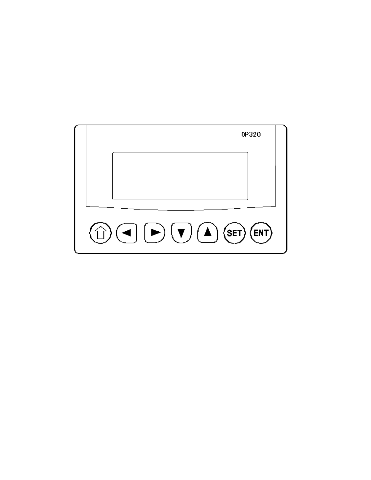
1-4Nam
ing
1-4-1 OP320/OP32
0-S
The
OP320(OP320
-
S),
has the
LCD display window,
and7user
buttons, The seven buttons
can be set to be special function keys,
sc
reen jump
oron-
off set and other function
s
.
Page 8

Page8of86Pages
Button
Basic
function
(These keys are not used as func
tion keys)
[ ]
Normally set
s
the main menu or the screen which is used most often to be the
system
’
s initial screen.
[ ]
When modifying the register
’
s data, shift the modified data bit to the left
.
[ ]
When modifying the register
’
s data, shi
ft the modified data bit to the right
.
[ ]
Previous page button or i
fin the status of data setting
,
the modified data bit plus
1.[ ]
Next page button or i
fin the status of data setting
,
the modified data bit plus
-1.
[SET ]
Press this key to start modifying
a
register
’
s value
.
[ENT]
E
xit
changing
a
register
s value.
Page 9
Page9of86Pages
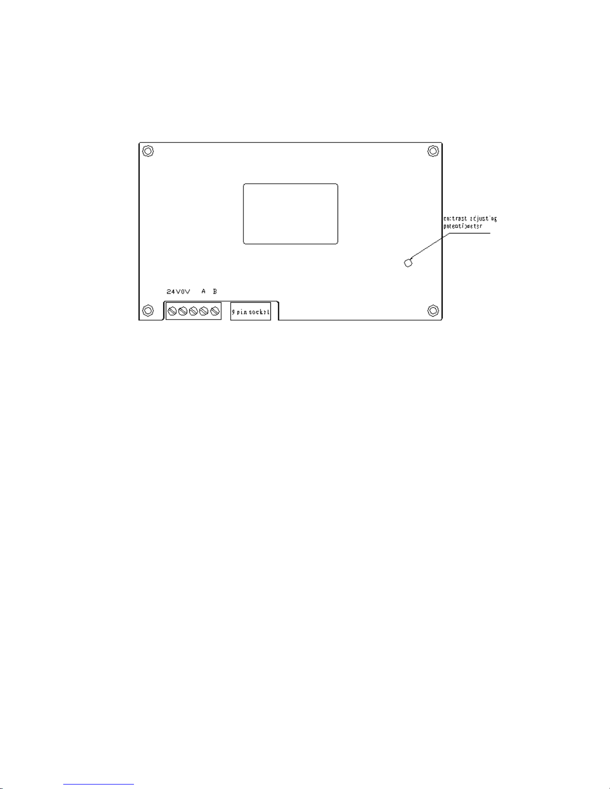
At
the back of OP320
(OP320
-
S), there
are
power
terminal
s
, communication
socket
and
contrast adjusting potentiometer.
OP320 display has back
light
auto turn
off if there
isnooperat
ion
for three minutes.
Page 10
Page10of86Pages
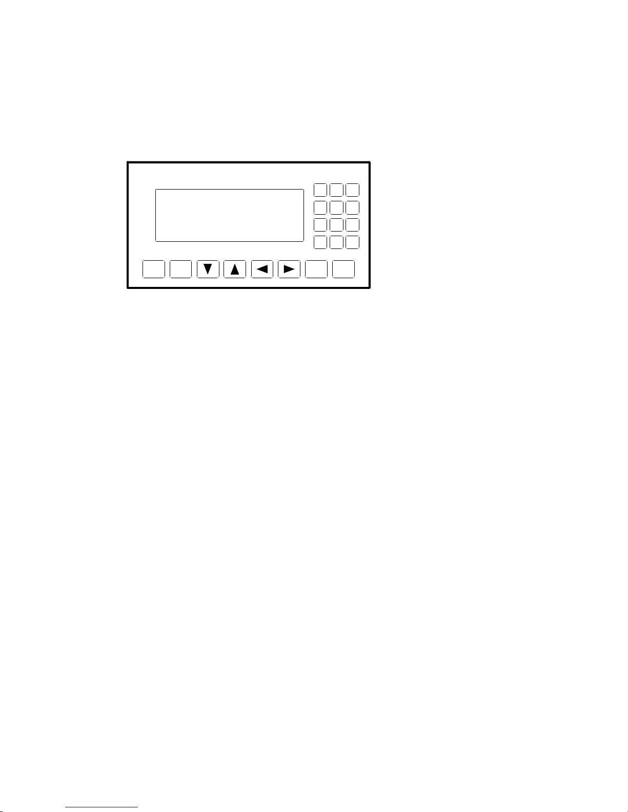
1-4-2 OP320
-
A/OP320
-A-
S
On the face of OP320
-
A (OP320
-A-
S), there is not only LCD display but also
20
button
s
for
user
special function.
R
efertoOP520
for detail button definition.
SET
ENT
ALM
ESC
CLR
+/ -
0
321654987
Page 11
Page11of86
Pages
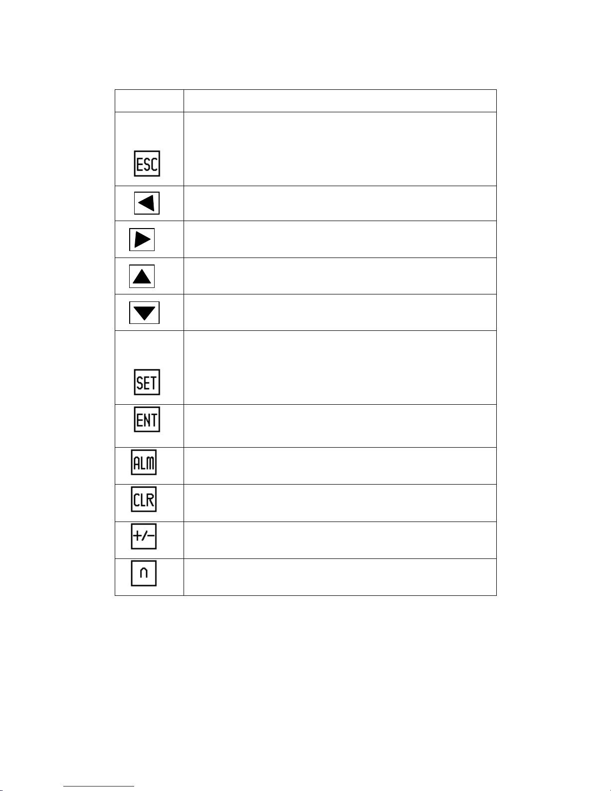
Table of key
s’
basic f
unction:
Key
Basic
function
Escape to t
he system
’
s initial screen is appointed by the user when
designing the screen
It can also be used as a function key.
It is used as a function key.
It is used as a function key.
It is used as a function k
ey.
It is used as a function key.
Press this key to start modifying
a
register
’
s value
.
Write the modified data to the register and then continue to modify the next
data.Alarm list key
(When the key is not set as a function key)
.
When mod
ifying the register
’
s data
,
clear the
value
areaWhen modifying the register
’
s data
,
it
setsthe data positive or negative
bit.
Number key (0
-
9),in the status of number be
ing
set,the modified number
bit change
s
to the correspond key value
.
Page 12
Page12of86Pages
1-4-2
OP520
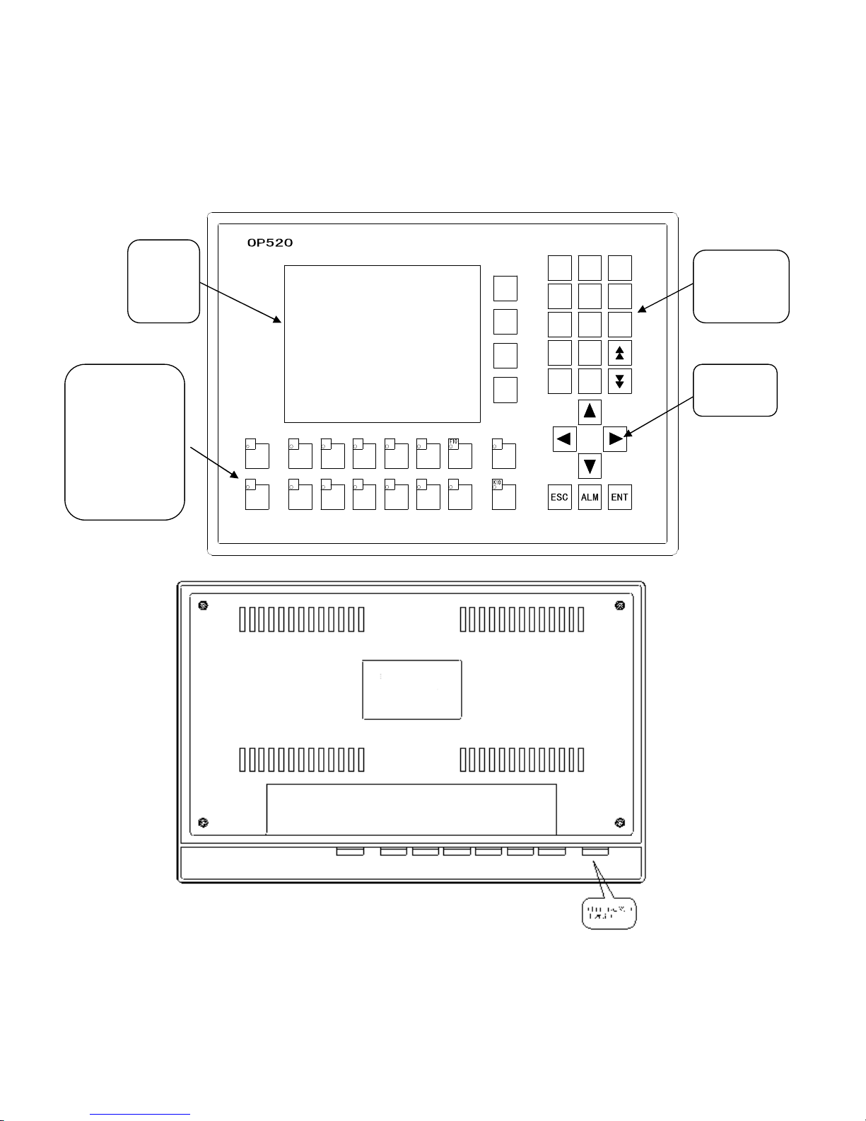
On the front of
OP520, there are not only LCD display window, but also 42 film
buttons
.
K3K1K5K4K6K8K7K9F6F5F7F8F9
SET
K2
F4F3F2
01CLR3+/ -
2F174685
9
LCD
display
area
Free define
multi
-
function
keys which can
extract and
insert card
(
16
in total
)
Number
keyboard
Direction
ke
y
Page 13
Page13of86Pages
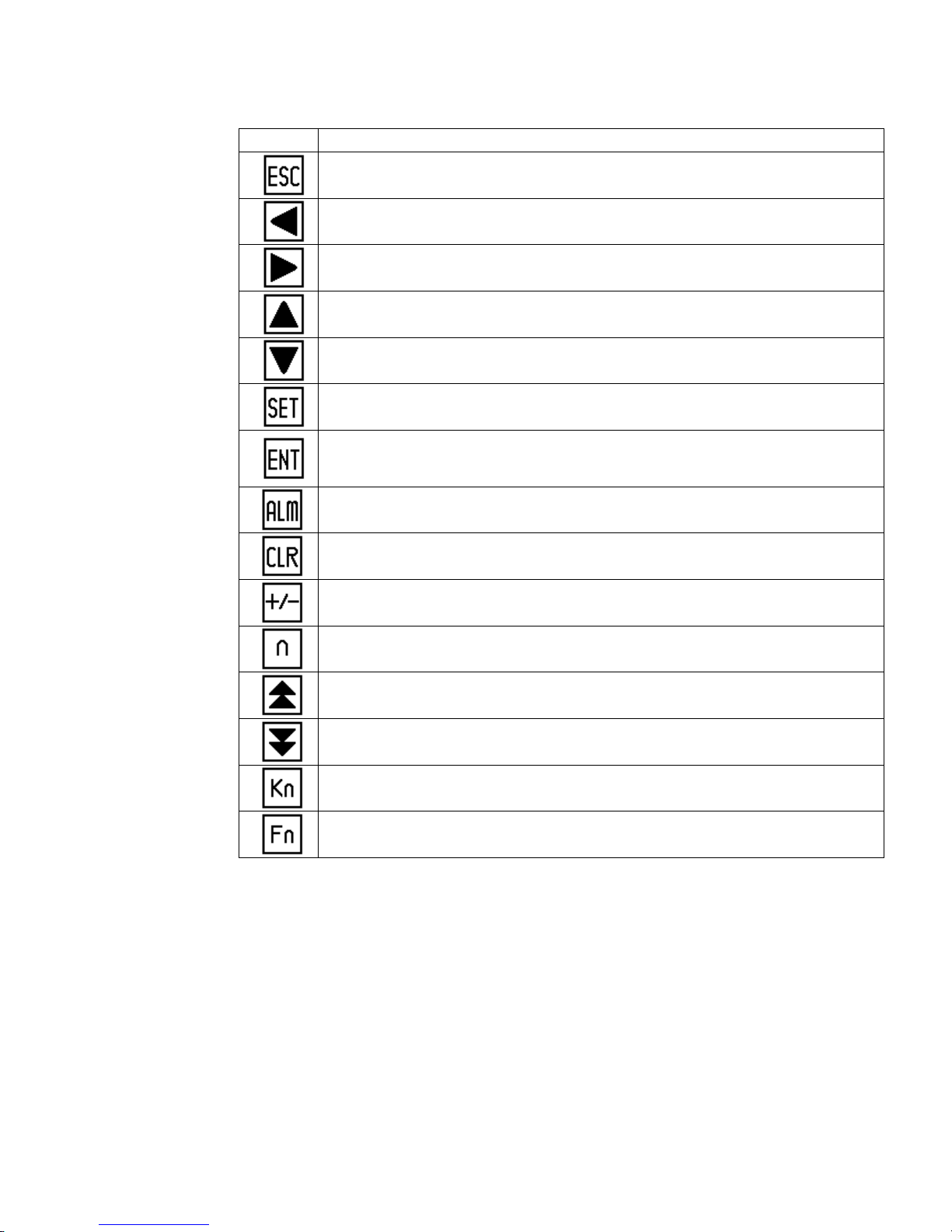
Button
’
s basic function table
Button
Basic function
Escape to t
he system
’
s initial screen is appointed by the use
r when designing the screen
It can also be used as a function key.
When modifying the register
’
s data, shift the modified data bit to the left
.
When modifying the register
’
s data, shift the modified data bit to the right
.The default value is the
current screen
’
s ID minus 1)
If setting
data,the modified data bit plus 1
T
he default value is the current screen
’
s ID plus 1)
If setting
data,the modified data bit minus 1
.
Press this key to start modifying
a
register
’
s value
.
Write the modified
data to the register and then continue to modify the next data
register
.
Alarm list key
,
after setting alarm list function
,
press this button to fast switch to the
alarm list screen
。
(When the key is not set as a function key)
When modifying the registe
r’s data
,
clear the
selected
area
When modifying the register
’
s data
,
it will
set the data positive or negative
Number key (0
-9).
Go to the previous data set register.
Go to the next data set register
Canbeusedasaglobal function key or no
rmal function key
Canbeusedasaglobal function key or normal function key
Page 14
Page14of86Pages
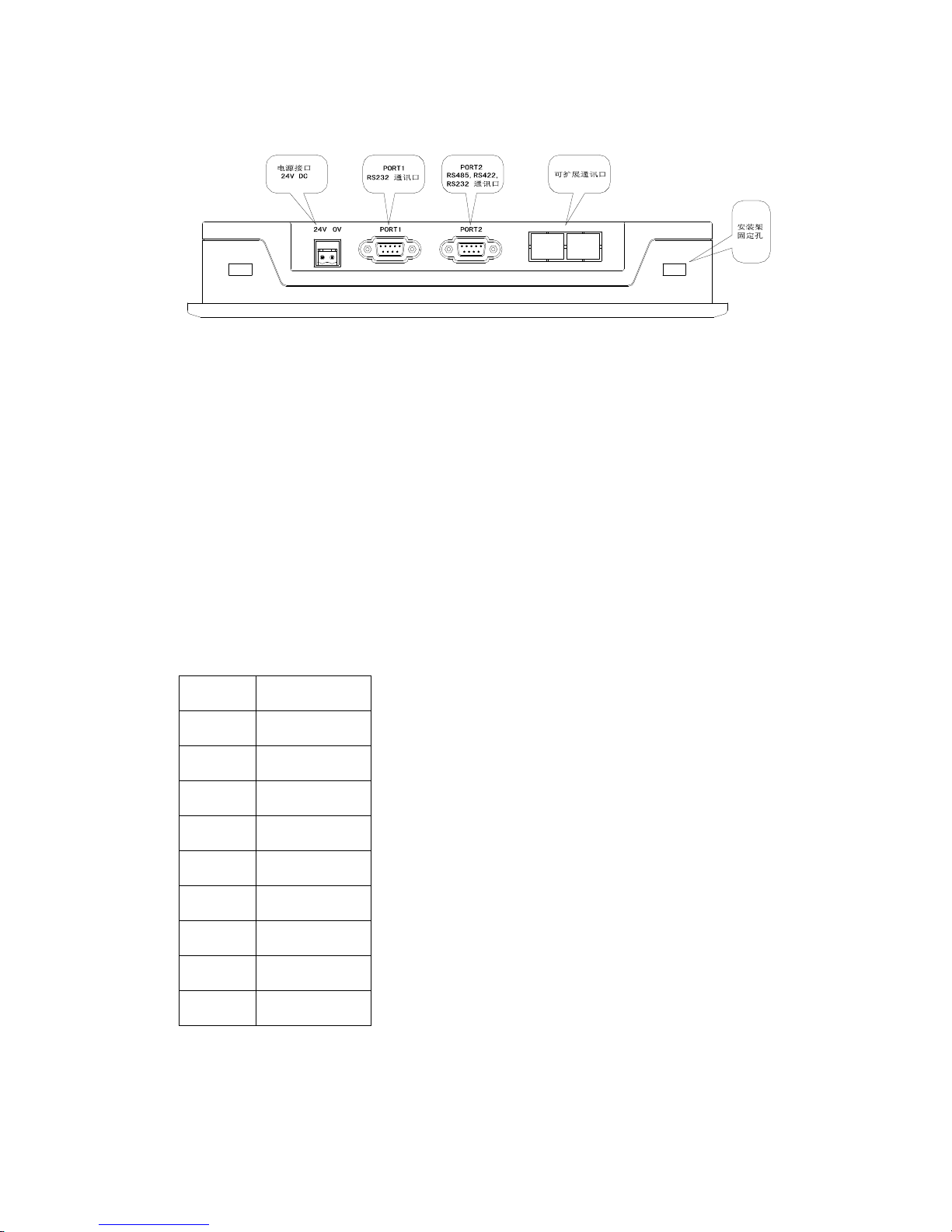
There are three communication
formats
for PORT2: RS232, RS422,
or
RS485. Connect
the
OP520
with any
series of PLC with the communication cabl
e, and you can
also
download using
the
same
communication
between
the
OP520
or the
PLC.
1-5 I
nterface definition and
connection
diagram
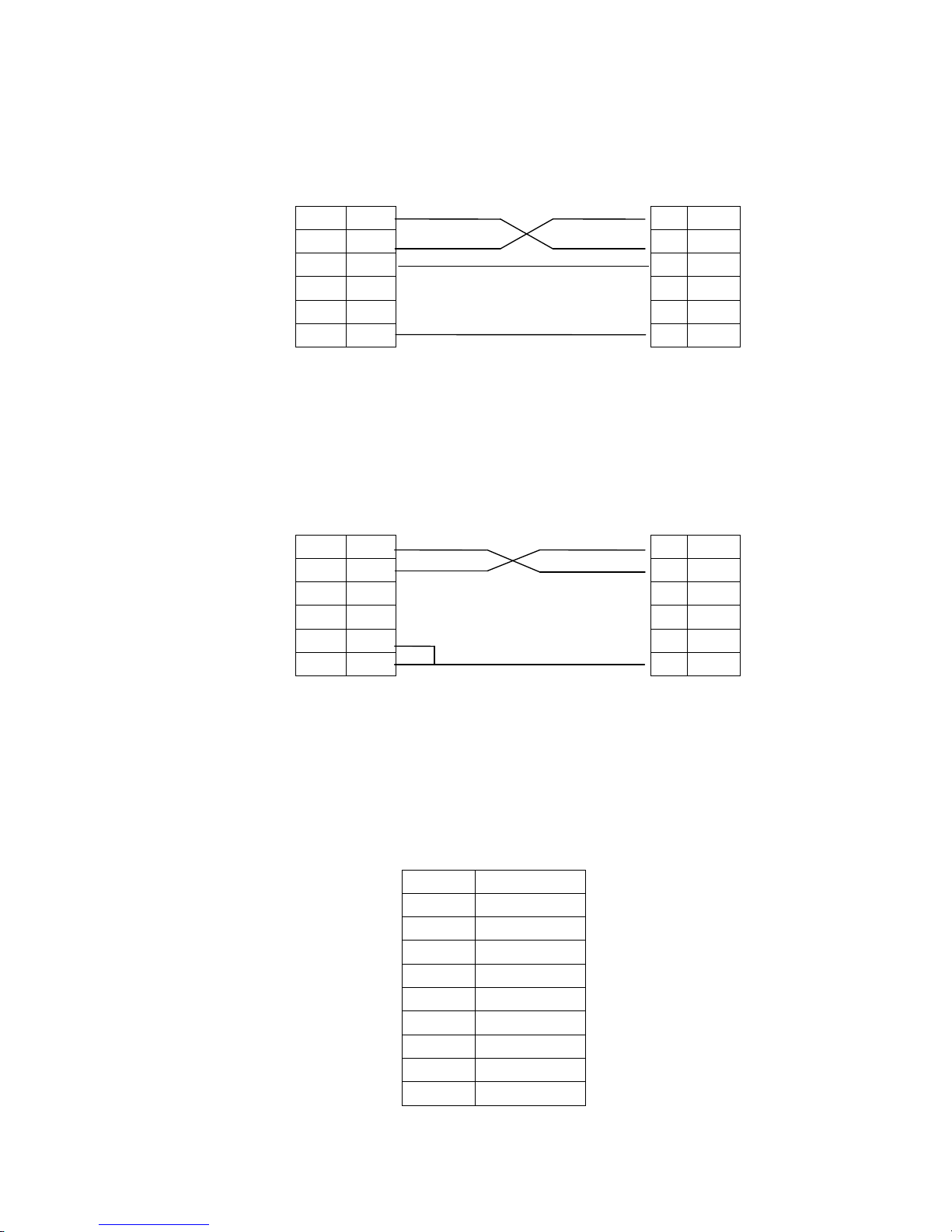
1-5-1 OP320
S
erial
pin
out for the
OP320
.
Pin ID
definition
1
TD+2RXD
3
TXD
45GND
6TD-78RD-9RD+OP-SYS-CAB connectin
g
diagram
Page 15
Page15of86Pages
OP side
(
9PIN
plug)RXD22
RXD
TXD33
TXD77
CTS
GND55
GND
OP-SYS-CAB connectin
g
diagram
:
(
V4.0
):
OP side
(
9PIN
plug)computer side
(
9PIN
plug)RXD22
RXD
TXD33
TXD7CTS4GND55
GND
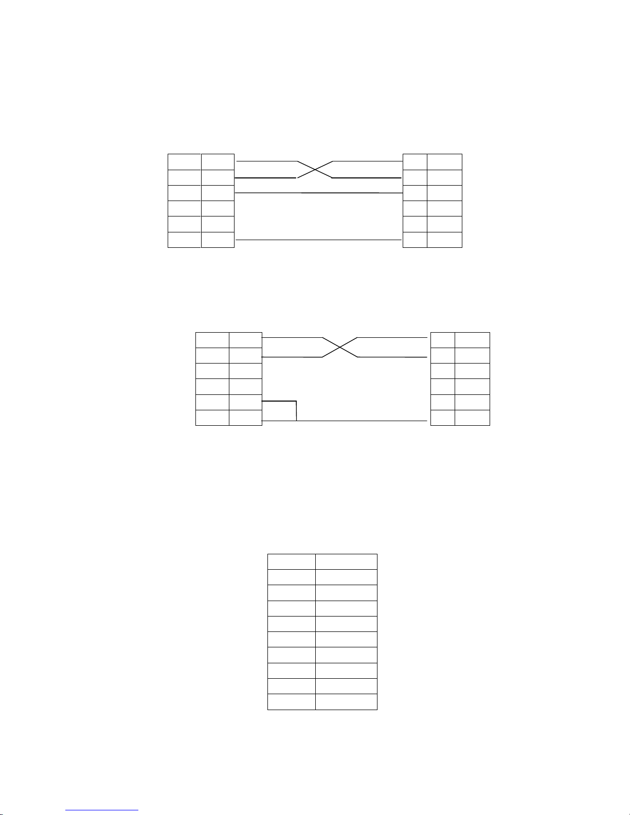
1-5-2 OP320
-
S
S
erial
port
pin’sdefinition ID
number
for the
OP320
-
S.
Pin ID
Definition
1
TD+2RXD3T
XD45
GND6TD-78B9A
Page 16
Page16of86Pages
OP-SYS-CAB connectin
g
diagram
:
OP side
(
9PIN
plug)
computer side
(
9PIN
plug)RXD22
RXD
TXD33
TXD77
CTS
GND55
GND
OP-SYS-CAB connectin
g
diagram
:
(
V4.0
):
OP side
(
9PIN
plug)computer side
(
9PIN
plug
)
RXD22
RXD
TXD33
TXD7CTS4GND55
GND
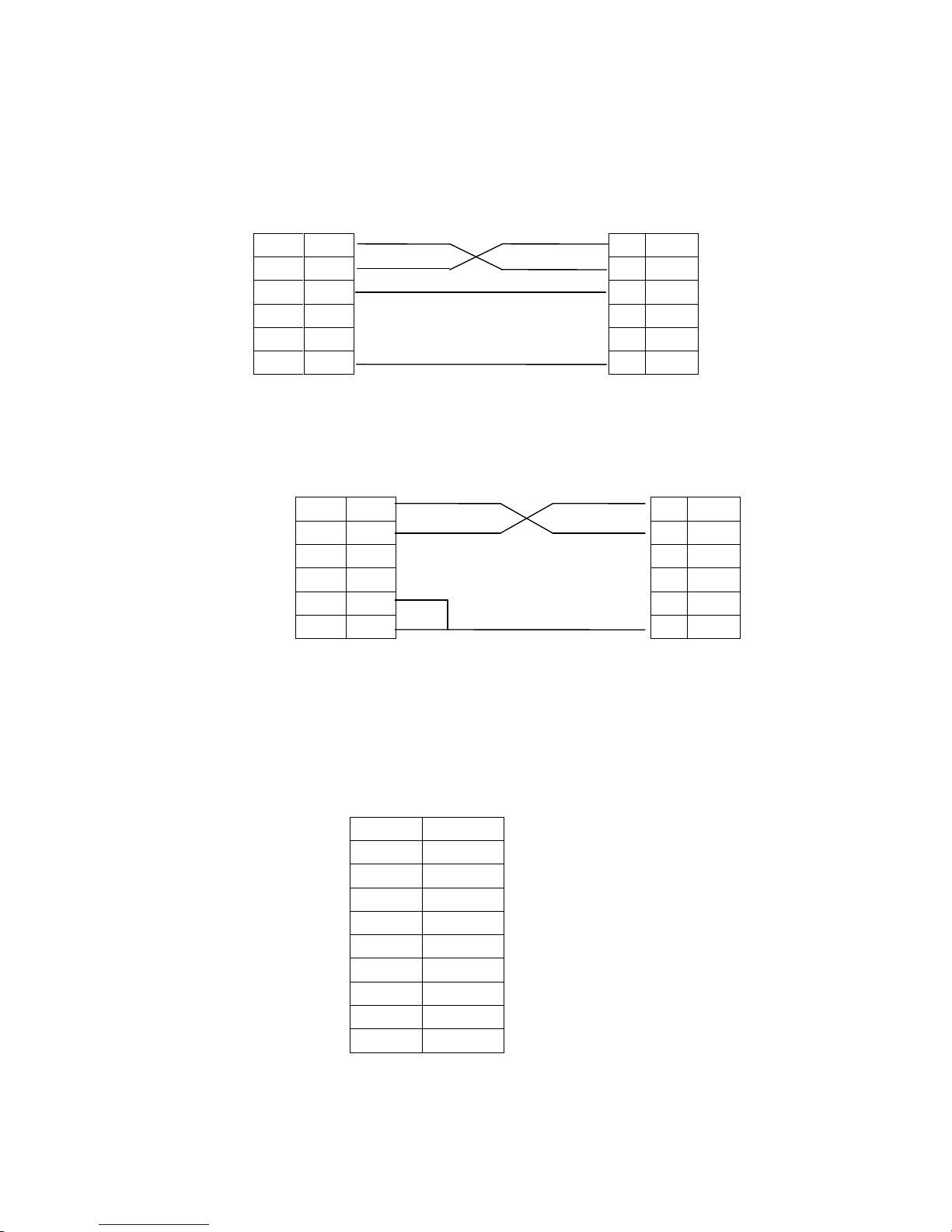
1-5-3 OP320
-
A
S
erial
port
pin’s definition ID
number of
the
OP320
-
A.
Pin ID
Definition
1
TD+2RXD3TXD45GND6TD-78RD-9
RD+
Page 17
Page17of86Pages
OP-SYS-CAB connectin
g
diagram
:
OP side
(
9PIN
plug)computer(9PIN
plug
)
OP-SYS-CAB connectin
g
diagram
:
(
V4.0
):
OP side
(
9PIN
plug)computer(9PIN
plug)RXD22
RXD
TXD33
TXD7CTS4GND55
GND
1-5-4 OP
320-A-S
S
erial pin’s definition ID
number of
OP320
-
A.
Pin ID
Definition
1
TD+2RXD3TXD45GND6TD-78B9A
RXD22
RXD
TXD33
TXD77CTS
GND55
GND
Page 18
Page18of86Pages
OP-SYS-CAB connectin
g
diagram
:
OP side
(
9PIN
plug)computer(9PIN
plug
)
OP-SYS-CAB connectin
g
diagram
:
(
V4.0
):
OP side
(
9PIN
plug)computer(9PIN
plug)RXD22
RXD
TXD33
TXD7CTS4GND55
GND
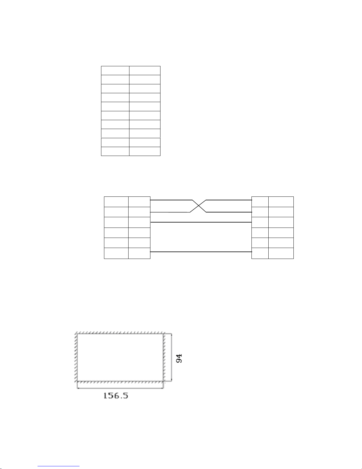
1-5-5 OP520
Serial port pin
’
s de
finition ID number of
the
OP520.
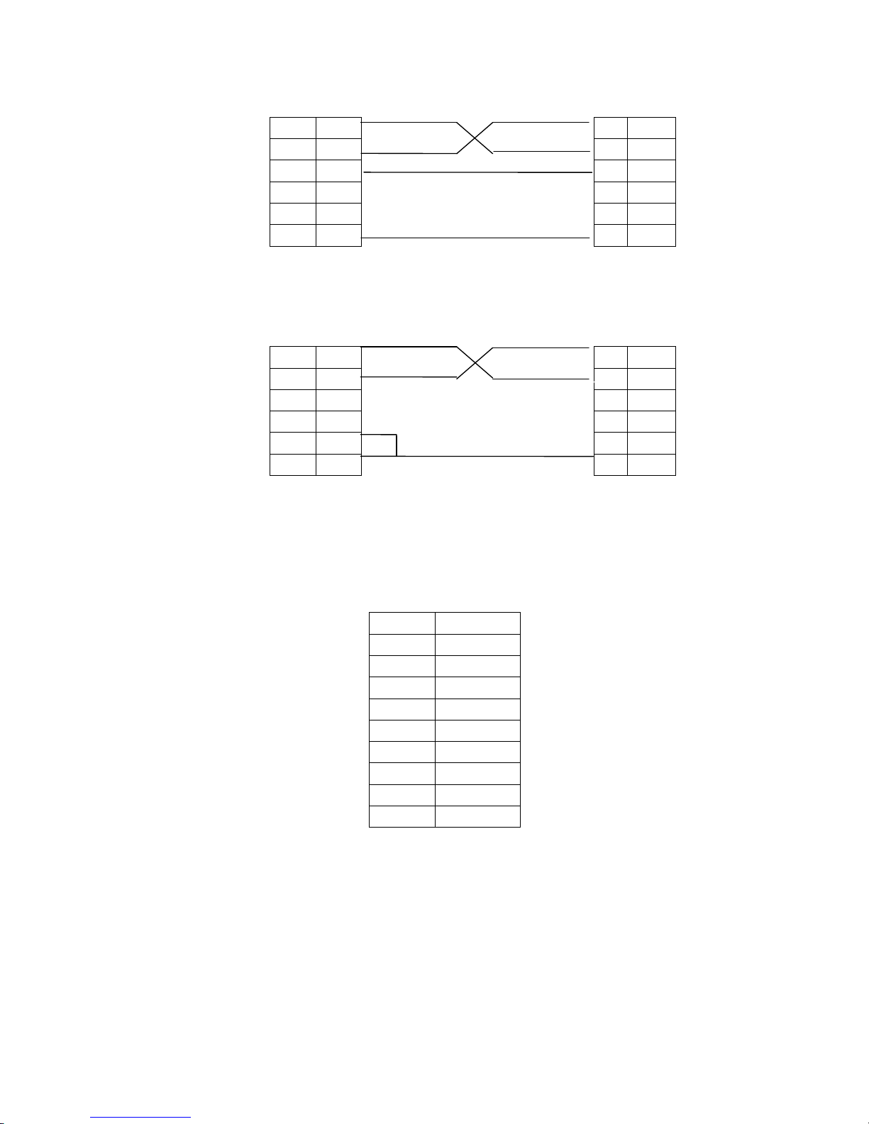
PORT1 (download port):
Pin’s ID
Definition
1NC2
RXD
3TXD4NC5GND
6NC7
RTC8NC9NC
RXD22
RXD
TXD33
TXD77
CTS
GND55
GND
Page 19
Page19of86Pages
PORT2 (communication port):
OP-SYS-CAB connecting
diagram
:
DP210
(
9PIN
female
)
Computer
(
9PIN
female
)
RXD
22RXD
TXD
33TXD
RTS77
CTS
GND
55GND
1-6Installing
methods
OP320
(OP320
-S)The product
’
s actual size
is
: 155.5×92.7×
50.4 (
in mm
)
The
cutout
sizeis:
156.5
×
94 (in mm)
Pin’s ID
Definition
1
TD+2RXD
3
TXD
4
Empty
5
GND
6TD-
7空8RD-9RD+
Page 20
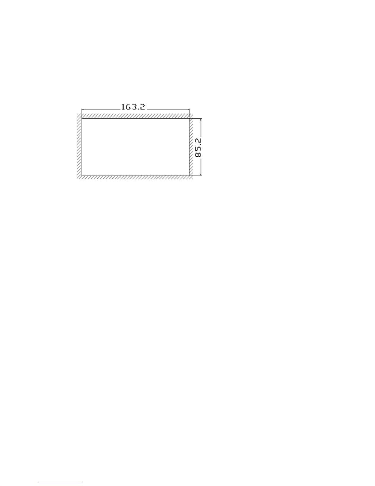
Page20of86Pages
OP320
–A(OP320
-A-S)The product
’
s actual size
is
: 1
62.2×84.2×30(in mm
)
The
cutout s
izeis:
163.2
×
85.2 (in mm)
OP
520 The product
’
s actual size
is:284×194×50(inmm)
The
cutout
sizeis:
269.2
×
156.4 (in mm)
Page 21

Page21of86Pages
Chapter 2
OP20
Software
2-1 Basic s
ummary
of
the
OP20
OP20 develop
s
software for character display
for the
OP series application screen. It runs
on
WINDOWS 98/2000
/XP
system.
2-1-1
Project sc
reens
The project
’
s basic element is
the
screens.
2-1-2
Screen content
You can place Characters, lamp
s
, switch
es
, data display set window
s,and next screen
keysand other element in each screen.
You can a
lso
set the
alarm list monitor
ing
.
Page 22
Page22of86Pages
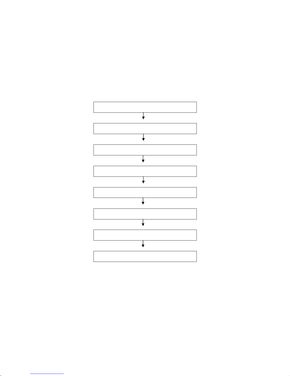
2-1-3
The us
e
flow
of OP20
The basic use flow
foranOP20
program
:
Set up the software.
Run the program.
Create or open
a
project
Create or open a screen
Edit the screen.
Save the
project
Transfer the screen.
Run
Page 23
Page23of86Pages
2-2Editing
the user’s screen
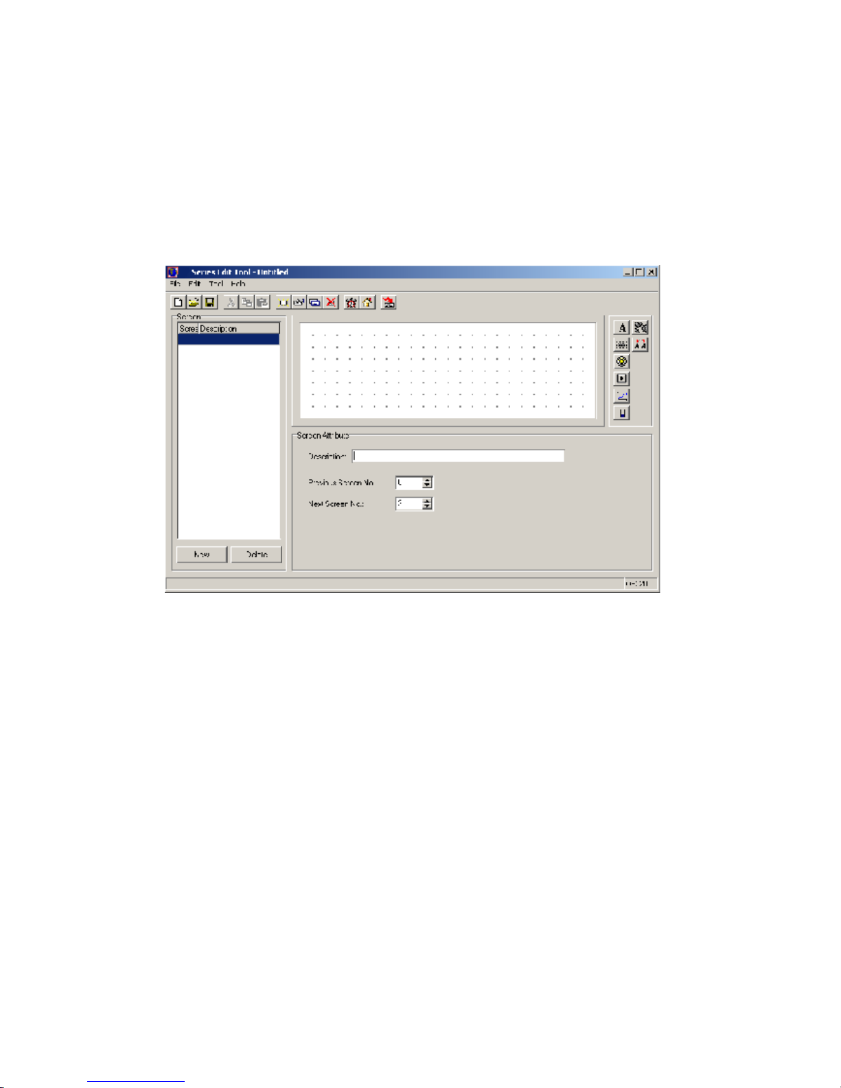
2-2-1Create a proje
c
t
After run
ning
the OP20 Software,
There will be a screen editor in the center of the
computer
’
s display.
Screen
Display all the screen’s serial number
in
the project.
Description
D
escript
ion of the screen fun
ction
“New”
key
Create a new screen.
“Delete”
key
Delete the current screen.
Page 24

Page24of86Pages
Key
Description
Create a new project
.
Open a saved project
.
Save a project
that
is editing currently
Cut the characters
in
the tex
t
box.Copy the characters
in
the textbox
.
Paste the characters
in
the textbox
.
Creat
e
a new screen,
Display the
normal
ty
content
ofthe
current screen.
Copy a screen to be another
one
Delete the current screen.
P
ointtothe system’
s
initial screen,
when
the display is working, click the
[ ]
button
to
return
back
to thi
s screen
.
Log in the
alarm list information,
each piece of
alarm information
correspond
s
withan
internal
relay.
Via RS232 port of
the
computer, download the completed project file to
OP320 display.
Page 25
Page25of86Pages
PLC typ
e
Select
the
PLC’s type
so w
hen
the
OP20
is
download
ed
the screen,
will
transfer the
appoint PLC
’
s communication protocol along with the screen data to the display.
2-2-2
Make a basic
screen
The following we will take Mitsubishi FX series PLC as the examp
le to describe:
First, enter the edit status of the system
’
s initial screen (If default it will be the No.1 screen).
In the bottom of the screen is the current screen
’
s (No.1 screen)
normal
ty
.
Page 26

Page26of86Pages
2-2-3The system parameter
s
of OP20
Click
button, or click “tool”
”set OP20” command
The ma
in
control screen
After
powering up
, the first screen OP320 displays
the main menu
.
Password
All the screens
in
a project use
the
same password, when the
encrypt
normal
ty of “data
set
window
”,
“fun
ction key” is va
lid,only when
the system’
s
password
hasbeen
opened
.
P
ower conservation
protection
The default value of the backlight hold time is 3 minutes. When
its
set it to be 0, the
backlight will light
stay on
.
Sampl
e
analog
quantity
data
OP320 ca
n connect with a 8
-
channel
analog
value
sample
module or a
n8-
channel
temperature sampl
e
module via
the
RS485 communication port.
The register
’
s head address which
the
analog quantity
is
auto store
d
is assigned by this
parameter.
2-2-4Text
B
efore ed
iting
the screen
,
describe the 8 elements
’
function in the right of the screen edit
window.
PartsFunction
Input
texts.
D
ata monitor window or data set
window
(The
address
isaPLC data register)
Page 27

Page27of86Pages
Indicat
ion
lamp, display
s
theon-
off
status of
internal
relay.
Function key,
all
the seven keys in the bottom of OP320 can be defined
as
function key
s.Create a real time trend
.
Bar is
used to display
analog quantities
parameter intuitively, such as
fl
ux
,
press
ure
,
liquid level
,
etc. Its
height,
w
idth
and direction can be appointed
randomly.
Insert
a bitmap file, it can display
the machine
’sdiagram
, make the
opera
tor easy to understand. It can also display the
mark
and
badge
of
the
factory
,
improve the product
image.
Dynamic
text
, display the
current
status of
the
machine
with
dynamic
text.Make the operator
easy
to operate,
improve the
produce
efficiency. Dynamic
text
is your
ideal
cho
ice.C
lick the
button, there
will be a rectangle dashed frame in the screen
Page 28

Page28of86Pages
Coordinate
The X value
status
s
this text’s
horizontal
position
The Y value
status
s
this te
xt’s
vertical
position
The coordinate origin point is
in
the
left
top
of the screen.
Special
Double
:
Display the characters multiply in horizontal and vertical.
Inverse
:
The color of the message and
the
background displays
inversely
.Message
. Theconte
nt
of this column
can be cut, copied or pasted.
E
.g.Display the text
“mainmenu”
in
inverse
. Input “ma
in
menu” in the set
column, and
select
the“inverse
”
in the
“
special
”
frame.
2-2-5Function ke
y
(screen
jump
)
C
lick
button, there
will be
a
dashed
rectangle frame
that
moves with
the
mouse.
Click
the left button
of
the
mouse to confirm the position of the function key.
Then there will be a
hand
diagram
and the function key
to be set in the window.
Page 29

Page29of86Pages
Key
In the pul
l down menu of
“
key”,
select
the appropriate key f
ro
m seven keys.
Hand
In order that the operator can operate
it
correctly and quickly, add a hand
diagram
in front of
the
button
.
Encrypt
This function key is
only valid
when the system’
s
password
has been
opened.
Set coil
The function key
’
s action
will
switch
the value
setting.
Screen jump
This function key’s action
will set the
screen jump.
Coil
No.:
Address of the PLCs coil.
Force
ON
Set the appointed
internal
relay to
be ON
.Force
OFF
Set the appointe
d
internal
relay to
be OFF
.Reverse
Set the appointed
internal
relay to be the reverse logic.
Momentary
ON
When the key been pressed down, set the appointed
internal
relay to be ON; when the key
popsup, set the appointed
internal
relay to be OFF.
Page 30

Page30of86Pages
Select a key i
n the pull
-
down menu of
“
key”, there are seven keys
Page 31

Page31of86Pages
After set
ting
the function key,
place text
“
set parameter
”
to the right of the button
diagram
to prompt the operator. Click
“<”key to enter parameter.
You can set the NO.20 screen to be the state set screen.
Page 32

Page32of86Pages
In the main menu screen, add an alarm screen jump key.
Y
ou can jump to the alarm list
screen, refer to the alarm information.
For the alarm information, you can refer to 2
-2-
14
Page 33

Page33of86Pages
2-2-6
Data display
window
Setting
methods of parameter display window
s
and parameter set window
s
in detail. Also,
how to set the password.
E.g. T
he NO.10 screen can monitor and set three
groups
of
parameters, with the production
of Class A
, Class B, Class C.
The
row
in the left is
the
current value
, the row
in the right is
the
target value. The current value can
only
be used to monitor the data, the target value can
not only monitor but al
so modify the data. The
relationship between the three groups of
parameters and PLC data register is
as
follow
s:The correspond address of
the
current value
The correspond address of
the
target value
The production of
Class
A
D100
D110
The production of
Class
B
D101
D111
The production of
Class
C
D102
D112
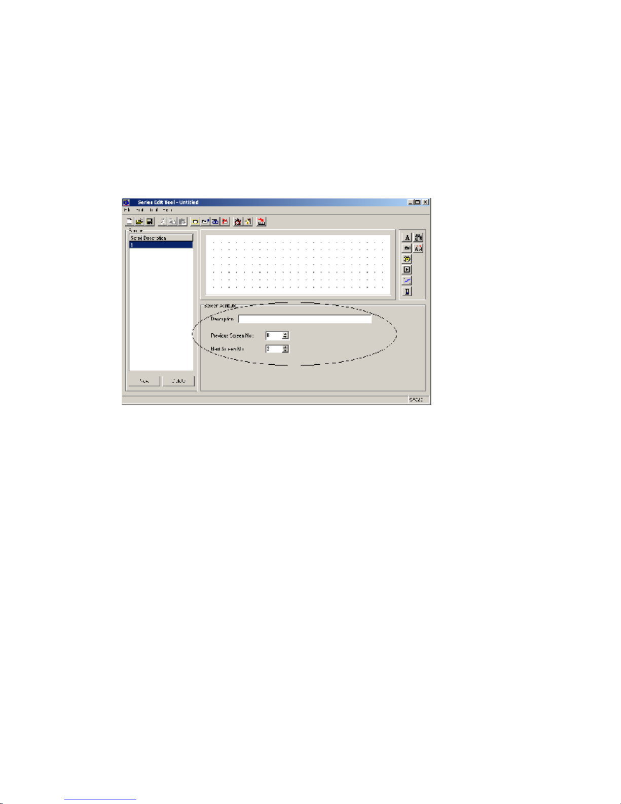
Click the [new] button,
there will be a dialog box of the screen
’
s ID No. and screen
description setting:
Screen
No.
The new screen’s
ID
number
Description
Describe
the new scr
een’s
normal
ty
.
Page 34

Page34of86Pages
Set the screen
No.
to be 10, enter the
screen description
“
set
parameter”.
Click
[OK] button to confirm. After that, there
will be
the content of screen
attribute
in
the
right
bottom of the screen. Set
the“Previous Scr
een No.
”
to be 0, set the
“
Next screen No.
”
to be 20. Then in the normal display status (not in the status of data setting), click
“∧”
key
to directly enter the main menu screen, click
“∨”
key to directly enter the state setting
screen
At
the
normal
position,
place
text “the current value”, “the target value” , “the production of
Class A”, “the production of Class B”, “the production of Class C”.
Page 35

Page35of86Pages
C
lick the
button, there
will be
a rectangle
dashed
frame mov
es
with
the
mouse, move
it to
normal
position
,
then click on the left button
of
mouse to confirm it.
Display
“
12345
”
these five numbers inside the dashed frame, that means that this element is
a register display window or regis
ter set window whose length is five bits.
Register
No.
PLC register
’sNo.R
egister number
Sequential display or set the number of registers, the minimum is 1, the maximum is 2.
Set
This
parthas the function of set
ting a value to the register.
E
ncrypt
Only when the system
’
s password
has
been opened can you modify the data, the password
value is set by the tool menu.
Digits
Display
or set the
data’s
max
digit
.Decimal
The number of
decimal places
.
Page 36

Page36of86Pages
Decimal
system
Display the data
in
the register in de
cimal
format
Signed
Select this
normal
ty only when
the
display data in decimal format,
if the highest bit of the
register is 1, then
display
the data in
negative
. e.g. FFFEH
equals
–
2.HEX/BCD
Display the data in
HEX.
In this example, set by the following
contents:
R
egister’
s address
=
D100; the number of
the
register = 1;
the digits of data
=4; the
number
of
decimal fraction
= 0; display in decimal system;
don
t display
negative data
.
Set the cu
r
rent values display window of Class B an
d Class C. The addresses of
the
registers
are D101 and D102
respectively
,
the
other
normal
ties are the same as
before
.
Page 37

Page37of86Pages
2-2-7Data set window
Click
button, there
will be a rectangle dashed frame which moves with the mouse in
the scree
n..Click on the left key of mouse to confirm.
In the register
column,
select
“set”,
the monitor function, the
element
also has
a
set function.
Page 38

Page38of86Pages
After
the frame
“
Set”been
selected
, add
another
two
option
s
: “
Encrypt
” and “upp
er/lower
limit
ation”.Encrypt
:All parameters can be protected by
a
password
. The method
s
of setting and
modifying
the password
isasfollow
s:Pick
“tool”
“set OP20” command,
there will be a
dialog box
:
set
OP series
:
Input
the
passwor
d or modify the
original
password, e.g. input password “5678”, then press
“OK”
button
, the password is confirmed.
Page 39

Page39of86Pages
U
pper/lower limit: can
be
set
. T
his will
limitaninput too large or too small. E.g. set the
upper limit to be 9000, the lower limi
t to be 0. Only when
0<
the
set value<9000
can the set
value be written into
the
PLC.
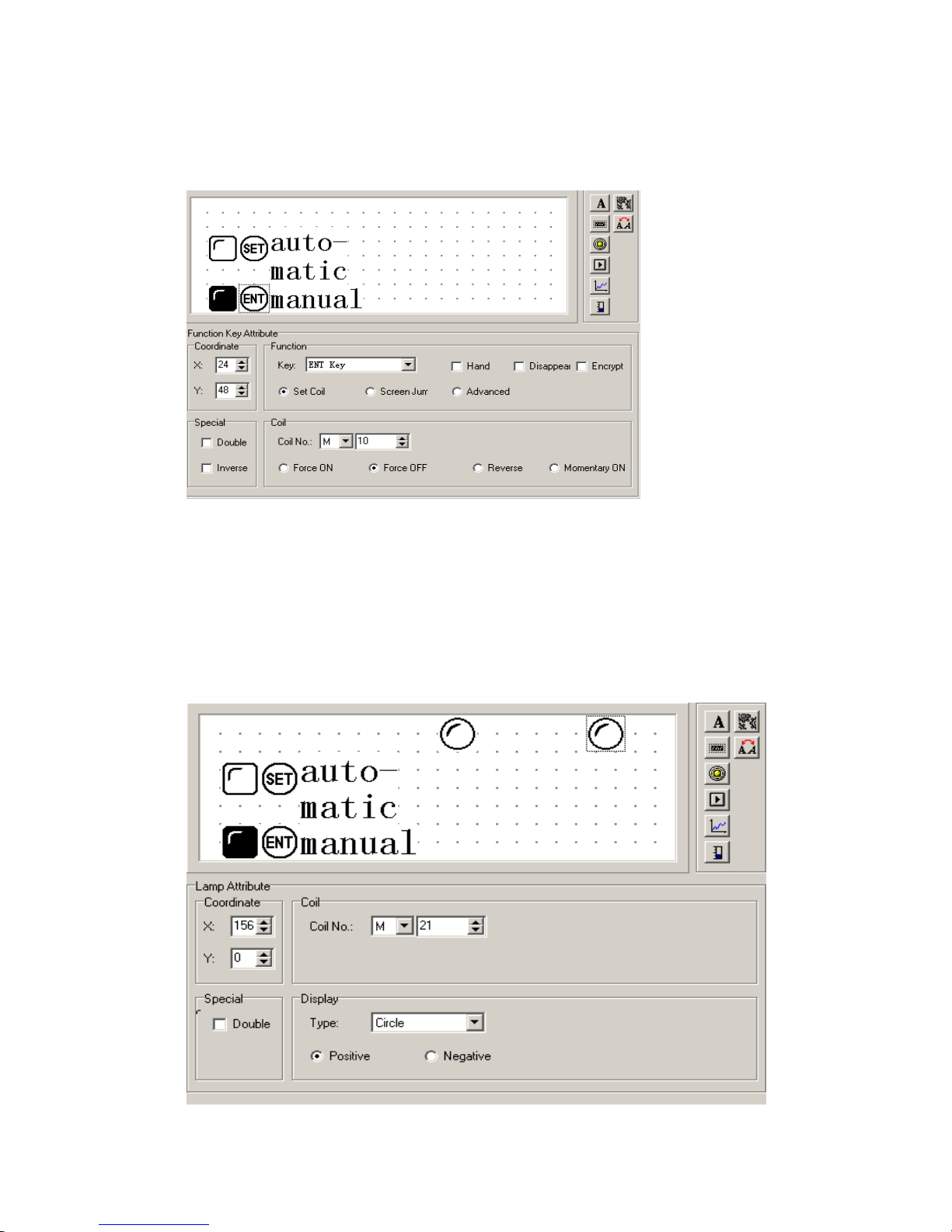
2-2-8Indicat
ion
lamp
s
H
ow to make a mode set screen. At the same time set
the
indicat
or
lamps and function keys
in detail.
E
.g.
The function of N
o.20 screen is to select the machine
’
s work mode. Manual/automatic
:
In the manual mode,
and to
control
the
machine
.
The status of the
internal
relay
The
content of
action
M10 = 1
Automatic mode
M10 = 0
Manual mode
M20 = 1
M
otor
run
forward
M21 = 1
Motor
run back
M20 = 0 , M21 = 0
M
otor stop
Page 40

Page40of86Pages
Click the [new] button,
and
popupa dialog box of
“
New Screen
”
. Set the screen
’
s No. to be
20,
and type
“
set mode
”
in the description.
Click [
OK]button to confirm.
Then there will be the screen
’snorm
altydisplay
.
Page 41

Page41of86Pages
Click
button to place the
status
lamp, there
will be a rectangle dashed frame
that
moves with the mouse.
C
lick the left key of the mouse to confirm.
CoilNo.
The define ID No. of the
interna
l
relayofthe PLC.
T
ype
The shape of the
status
lamp,
either
square
or
circle.
Positive
When the relay is ON, the
status
lamp display
insolid
Negative
When the
internal
relay is ON, the indicator lamp display
in
vacant
Page 42

Page42of86Pages
S
et the coil’
s
No.tobeM10, select the
square
lamp;positive logic. Then in the window
there will be
a vacant
square
status
lamp.
Click the
button to lay the function key, there
will be
a rectangle d
ashed
frame
which
moveswith
the
mouse, t
hen move it to the
normal
position and click on the left key of
mouse to confirm it.
Page 43

Page43of86Pages
In the function column, select the “SET” button to
be
the
auto mode setting button. S
et the
coil’s defin
ition
No.tobe
M10, and
set
the
action
mod
e tobeON..
Place text
“
automatic
”
to the right of the button., it means that this button
’
s function is
select automatic mode.
Page 44
Page44of86Pages
Set the manual button and the manual status lamp
with
the same method. The ad
dress of the
lampisstill M10.
Select
the display
normal
ty negative logic. The butto
n
is “ENT” button,
the button
’
s function is
to
set M10 relay OFF.
Set two circle lamps, positive logic. Each one
’
s address is M20 and M21,
to
monitor
the
motor
’
s work
ing
states. When the lamp in the left lights, it means the motor is
running
forward
, when the lamp in the right lights, it means the motor is
running
back.
Page 45

Page45of86Pages
2-2-9Function key (switch
quantity operation
)
C
lick
button to place the function key, select “>” button,
the
correspond address is
M20, its function is
momentary
set
M20 relay to
be
ON, and
keep
the hand
diagram
. It
status
s that when
you
click on the “>” button, M20
of PLC
is set to
be
ON, an
d the
motor
begins to
run forward
.
(PLC program, us
esM20 to trigger Y0); when
you
releas
e
the “>”
button
,
M21
of PLC
goes back
to
the
OFF
state,
, and the motor
will
stop
running.
Page 46

Page46of86Pages
2-2-10Single
line
Trend
Inthe
proce
ss
industry
,
the value of
some parameters
change
slowly.
The operator want
stoknow
these parameters
’
change process in a certain time. The
trend
diagram
is the best way
to display these values.
Click the
b
utton, there
will be a rectangle dashed frame moving with the mouse.
Move to the
desired
position and click the mouse
’
s left key to confirm.
Register
No.
The
address correspond
s
with the
trend
diagram
.Full
value
When the
trend
diagra
m
displays in 100% scale, the value
correspond
s
with the
register
Z
ero value
When the
trend
diagram
displays in 0% scale, the value
correspond
s
with
the register
S
ampled
ata (the number of the dot
s)The number of all
the
sampled dot
s
from left to right.
The larger th
e
number, the
more
detailed
the
trend
has.Sample
cycle
The inter
v
al time of every two sampl
ed
dots.
Range
This value
sets
the length and the w
id
th of the
trend
diagram
.
Note:
One
trend
diagram
element can only display one line.
Page 47

Page47of86Pages
2-2-11Bargraph
.
Click the
button, there
will be a rectangle dashed frame
that
moves with the mouse.
Move to the
normal
position and click the left key of the mouse to confirm.
Register
No.
The
register
’saddress correspond
swith the
bar graph
.Full
value
When the bar
graph
displays in 100% scale, the valu
e
correspond
s
with
the register.
Z
ero value
When the bar
graph
displays in 0% scale, the value corresponds with the register.
Direct
The display direction of the bar, it can b
e up, down or be left, right.
Range
This value
d
ictates
the length and the w
id
th of the bar.
Page 48

Page48of86Pages
This bar monitor
s
the value in D300. When the bar displays in
the full
scale, it
status
s that
the value in D100 is 100;
w
hen the bar displays i
n 50% scale, it
status
s that the value in
D300 is 50.
2-2-12Diagram
display
Insert a bitmap
file
, which can
display the machine
’spicture
and make
s it easy for
the
operator to understand. Also it can display the factory
’slogo
, badge
.
Click the
button, there
will be a search dialog box in the screen.
Select the bitmap
file
which
you
intend to display, then double
-
click it or click on the open
button, there
will be a rectangle dashed frame
that
moves with the mouse. Move
it
to the
no
rmal
position and click the mouse
’
s left key to confirm.
Page 49

Page49of86Pages
Note: it can display
a
bitmap
with
192×64 pixel
s at most.
The
extra
part w
ill
be removed
automatically.
2-2-13
Dynamic messages
You can d
isplay the current machine
’
s status via words
which
makes
the operator
s job
eas
ier,and
will improve the monitor
ing
efficiency. The dynamic message is your
best
choice.
Click the
button, there
will be a rectangle dashed frame
that
moves with the mouse.
Move to the
normal
position and click th
e mouse
’
s left key to confirm.
Page 50

Page50of86Pages
In the screen
’
s edit area, there are some initial words
“
dynamic message
”
and the following
normal
ties in the dialog box.
Register
No.
The register
’
s No. of
the
PLC
.Decimal
Value format.
HEX/BCD
Display the data in hex
system
.Display
Textedit
area
. Write the text
that need
stobe displayed.
Value
Data in the PLC register.
Content
Now, begin to edit the
content
. First, select the line
to
be edited, then click the left key of
mouse, “
D
ynamic
Message
”
.
Page 51

Page51of86Pages
E.g. Input
“
No.1 motor
runs forward
”
in the first line, input
“
No.1 motor
runs in reverse
”inthe second line, input
“
No.1 motor stop
s”in the third line.
The dynamic message responds
to
data in D200. If data in D200 hasn
’
t been set, then the
text fr
ame has no display, if data in D200 is 0, then display
“
No.1 motor clockwise
”.If data in D200 is 1,then display
“
No.1 motor
…………
”.If
data
in D200 is 2, the
n display
“
No.1 motor stops running
”
.
Page 52

Page52of86Pages
2-2-14Alarm list
Each project of
the
OP320 can set a group of alarm list information. A piece of alarm
information corresponds with a
internal
relay. The definition No. is sequential. The
internal
relay’s initial address can be set by the user accordin
g to the actual program. When any of
the
internal
relay turns to ON from OFF, that means that when there is an alarm,
the
OP320
will auto
matically
popupthe alarm display screen, then display
s
the alarm information in
the first line. When another
internal
relay be ON, display a new alarm information in the
second line.
Click the
button,
there will pop
up
t an
alarm list dialog box:
Page 53

Page53of86Pages
Input other information
in
the same way.
After all the
alarm information
been
input
, change the coi
l’s
No.tobe
M100
(example), i.e.
it
status
s that M100 to M106
i
ndividually
correspond
s
with the 7 alarm
s.
The operator can
immediately
reacttosolve
the
problem.
If
you
want to return b
ack to the
monitor screen,
just
click [ ] button.
Page 54

Page54of86Pages
2-3Save
a
project
After
finish the
screen edit
ing, you can save
the
project file, and
download
the screen
project to
the
OP20
.
Press
button,
in
the
screen
there will be a dial
og box for you to save the project.
Select the correct path and file name to save it, and the file’
s
extend name
will auto
matically
be
defined to be
.dp2 .
Input the file
name
, select the
right
path, then press “save” button to save it.
2-4 D
ownload
ing
t
he screen
Connect the computer
’
s 9 pin RS232 port and the 9 pin port of OP320 with the
download cable. Make sure that OP320
is
power
ed.Click the
button to begin
download
ing
the data
.
Note:
In the process of downloading the screen
’sdata,
make sure that
the
OP320
does
not
lose
power
After finish
ing
transferring the screen, there will be a dialog box,
that says
all the screens
have been transferred.
Page 55

Page55of86Pages
Turn off the display’s power. Pull out the
screen
’
s transfer cable
OP-SYS-CAB0, c
onnect
the
OP320 and PLC with the PLC communication cable.
T
here will be
“
communicating
”inthe right bottom of the display, that means OP320 is communicating with PLC.
Page 56

Page56of86Pages
Chapter 3
OP320
O
perat
ion
method
s
3-1Online communication
Note:
N
o m
atterifthe PLC is running or program
ming
,
the
OP320
will
operate
normally.
3-2
Shift
the screen
O
P320
will first
display the NO.1 screen. (
B
ecause the system’
s
initial screen is
No.1screen
.)The No.1 screen is a menu screen
.
Now, data in the left column displays the three classes
each, corresponding with
the
PLC’s
address: D100,D101,
and
D102.
Page 57

Page57of86Pages
3-3System’
s
password
B
efore modify
ing
the data, you should
first
open the system’
s
password.
Press
the
password
select
key,and type the password.
Click the
button to enter the password screen, the screen display
sthe
following:
Select 1, execute the operation of opening password; select 2,
to close the password
. Click
on the button, return
ing
back to
the
monitor status.
Page 58

Page58of86Pages
Select 1, the screen display
s:Click the “
∧
” button or “
∨
”button to
input
the password’
s
value,
and
click the “ENT”
button to confirm.
If the password value is correct, the screen displays:
If the password value
isinerror, the screen displays:
Select 2 , c
lose the password, the screen displays:
Page 59

Page59of86Pages
3-4Modify
ing
the data
value
If the password has been
entered
, click the
“ENT” button.
The p
roduction set value of class
A will
high light
, which means
you can
set class A
’
s production
value.
C
lick the “
∧
” button
and “
∨
” button to modify the value, click on the “<” and “>” to set the
digit’s position
, the
data range
i
s 0 to 9.
3-5Switch value
After the set value, click the
“ ” button to return back to the
system
’sinitial screen
(the
NO.1 screen.)
.
Click the
“>” button to enter
status set
screen
.
Page 60

Page60of86Pages
Chapter 4 New addition
al
function
softhe
OP520
4-1 Set
ting
general function key
When editing the project screen of
the
OP520, press
the
key, there will be a dialog box
for you
to set the general function key.
The dialog box displays 20 function keys (K1~K10,F1~F10), If the function key is not set,
it means that this key can only be used as the normal function key. Only when the display
’sscreen show
s
this function key can it
be effective to operate this key. After setting the global
function key, the display will display any screen
.
4-1-1 Set
ting a
coil’s function
In the
“
set the global function key
”
dialog box.
Select
“
set coil
”
for K1, the dialog box will
display coil set o
ption:
Page 61

Page61of86Pages
★
Force ON
When the key is pressed down, set the
coil
ON.★Force OFF
When the key is pressed down, set the
coil
OFF.
★
Reverse
When the key is pressed down, set the
coil
in reverse.
★
Momentary ON
When the key is pressed down, set the
coil
ON, w
hen the key pops up, the
coil
will be
set OFF.
Set encryption
Select
encryption multi
-
select frame. Then the function key will have the function of
the
password protection. Press this button, there will be a password check screen.
Page 62

Page62of86Pages
4-1-2 Screen jump function
In the
“
Set General Function Key
”
dialog box, set function key K1 to make it have the
function of screen jump. The dialog box will display screen jump
select
:★Screen
T
he screen will jump to one which
has the
number in the number
select frame as the
screen No.
★
Password
T
he screen will jump to the password check screen.
★
Alarm list
T
he screen will jump to the alarm list screen
★
Date/time
T
he screen will jump to the Time/Date screen.
Page 63

Page63of86Pages
Set the encryption
Select
the
encryption check box, then the key will have the function of
the
password
protection.
4-1-3 Advanced function
s
In the dialog box
“
Set Global Function Key
”,select
the advanced function
s
for K1.The
dialog box will display advanced function option:
★
RUN
The
PLC will
go into run mode
.★STOP
The
PLC will
go into stop mode
.
After
you
finish setting the global function key, press [OK] button, then the set global
function key will be
saved.
Page 64

Page64of86Pages
4-2 Status lamp
s
There are 16 button
status
lamps in the left
bottom of OP520, they can display the register
’sdata, it will reflect the machine
’
s work status.
Press the key, open the system setting
.
Select
the display function for the status lamp. The 16
button
status
lamps
are each
controlle
d by Bit0
-Bit10 of D0 register.
Bit7
Bit8
Bit5
Bit4
Bit3
Bit2
Bit1
Bit0K1F5F6F7F8F9
F10K2K3K4K5K6K7K8K9
K10
Bit15
Bit14
Bit13
Bit12
Bit11
Bit10
Bit9
Bit8
E.g. If you want to light [K1]
status
lamp, then Bit7=1, D0=H0080.
If you want to
light [K3]
status
lamp, then Bit3=1,D0=H8000
.
Page 65

Page65of86Pages
4-3 Application examples of global function key
s
and button
status
lamp
s
In t
he following
example
, we will start/stop the motor with the global function key. A
nd
use
the panel
status
lamp to
monitor the
ON/O
FF status.
Create a new project, in the display
s
selected
dialog box,
select
OP520.
Select
Mitsubishi in
the PLC
select
ion
dialog box
and
press
the
key.Set [K1] to make it the general function key, its function is set M0 momentary ON.
Set [K3]
to make it the general function key, its function is set M1 momentary ON.
Set the correspond address for the
status
lamp, single click
the《Toolbar
》
menu:
Page 66

Page66of86Pages
Single click
《
Set OP Series
》
Select
《
Light Panel Status LED
》
check box, the correspond
ing
word address of the 16
status
lamps is D0.
Program the
Plc
with
the following action:
If M0=1 Then SET Y0 RST Y1 D0=H0080
If M1=1 Then RST Y0 SE
T Y1 D0=H8000
Page 67

Page67of86Pages
4-4 in
ternal
clock (optional)
To s
et the clock, click
the
button, or click
“
Tool”->“
Set OP Series
”
command, there
will be a OP20 system parameter setting dialog box:
Select
“
Use Data/Time Module
”,and
set the control register
’
s No.
if
you use. E.g. D46,
then the clock
’
s data will be placed into three groups of registers which start with D46. D46
will store of year and month, D47 will store date and hour, D48 will store minute and
second.
After finish setting the clock, set a bu
tton with which we can enter the clock
display
screen:
.
Page 68

Page68of86Pages
Chapter 5 Application examples of
the
OP520
5-1 Examples
In the
following
example
we will take our company
’sE
C series PLC to make a project.
Page 69

Page69of86Pages
Page 70

Page70of86Pages
5-1
Make a screen
Open
the
OP20 screen set tool
and
create a new project,
selected
dialog box from the program.
Select
OP520 and click OK.
There will pop
up
a PLC
select
ion
dialog box. In the pull down menu,
select
econ E
C series
and click OK. Then you can start screen
edit.
Now f
irst, edit the main screen, here No.1 screen has
defaulted
(the program
default
s
it),
select
No.1 screen to be the main screen. In the screen
description
text, fill in the main
screen.
To i
nsert a
diagram
: Press
the
button,
Select
the LOG
O
diagram
that has been
made and insert it in, place the
diagram
to the
normal
position in the screen.
Page 71

Page71of86Pages
Chapter
6
OP320
-
S, OP320
-AOP320
-
A/OP320
-A-
S
OP320
-
A/OP320
-A-
S is a
cut down
version
of OP520, you can refer
to
OP520
for
its use,
but there is no
global set function key
s
, you can refer
to
OP320
for
its us
e
and refer
to
OP520
for its number keys
’
.
Page 72

Page72of86Pages
Chapter
7
PLC’
s
connection method
7-1
Econ
E
C series
PLC
OP series can communicate with
econEC series
PLC
, the
communication
port is the
PLC’
s
program port.
Item
Content
OP320
communication port
9 pin
communication port
PLC
communication port
Program port
The default communication
parameter
9600 bps, 8 bit, 1 stop, ODD
ID1Communication distance
(the
farthest)
15 m
Communication
format
RS232
The type of the cable
OP-FC-CAB0
The corresponding addresses of the
switch value
M0-M383
The corresponding addresses of the
digital value
W0-W2047, FW0
-
FW191, TW0
-
TW127,
CW0
-
CW127, WX0
-
WX13, WY0
-
WY13,
WM0
-
WM23
Page 73

Page73of86Pages
The connect
ion
diagra
m
of OP
-FC-
CAB0
2 RXD
5 TXD
OPside3 TXD
4 RXD
PLCsid
e(9PIN
)
(
8PIN
)
5 GND
8 GND
Note: it is
normal
for all OP series
models
7-2
Mitsubishi
FX series PLC
OP series can communicate with all FX series of Mitsubishi
at present
. The
communication
port is PLC program port or FX2N
-
422BD module of
theFX2N series PLC.
Item
Content
OP320
communication
port
9 pin
communication
port
PLC
communication
port
Program port or FX2N
-
422BD
The default communication
parameter
9600bps, 7bit, 1 stop, Even
ID0C
ommunication
distance
( the
farthest)
70 m
Comm
unication
format
RS422
The type of cable
OP-FX-CAB0
FX0S
FX0N
FX2N
The corresponding addresses of
the switch value
M000
-
M511
M000
-
M511
M000
-
M511
The corresponding addresses of
the digital value
D00-D31
D000
-
D255
D000
-
D511
Page 74

Page74of86Pages
The connect
ion
diagram
o
f OP-FX-CAB0
1 TD+
2RD-
6 TD
-1RD+OPside8 RD
-4TD-PLCsid
e(9PIN
)
9 RD+
7
TD+(8PIN
)
5 GND
3
GND
Note: it is
normal
for OP320, OP320
-
A, OP520.
7-3
Siemens
S7-200 series PLC
OP series can communicate with
the
program port
or extension port of S7
-
200 series PLC
via PPI protocol.
Item
Content
OP320
communication
port
RS485 communication port
PLC
communication
port
Programming port or expansion port
The default communication
parameter
9600 bps, 8 bit, 1 stop, Even
ID2C
ommunication distance
(the
farthest)
100 m (twisted
-
pair)
Communication
format
RS485
The type of the cable
OP-S7-CAB0
The corresponding addresses of the
switch value
M000
-
M317
The corresponding addresses of the
digital value
VW000
-
VW4096
Page 75

Page75of86
Pages
The con
nection
diagram
of OP
-S7-
CAB0
1OPside93 A
PLCside9
plug68 B(9PIN
)
8
Note: it is
normal
for OP320
-
S, OP320
-A-
S, OP520.
Page 76

Page76of86Pages
7-4
Omron
C series PLC
CPM1A, CQM1
-
CPU11 has only one communication port.
In orde
r to communicate with
the
OP320, it needs the communication cable CIF01
-
CAB produced by our company to
transfer the program port
’
s signal to RS232 signal.
ItemContent
OP320
communication
port
9 pin communication
terminal
PLC
communication
port
Program
port or expansion port
The default communication
parameter
9600 bps, 87bit, 2 stop, Even
ID0Communication distance (the
farthest)
15 m
Communication
format
RS232
The type of the cable
OP-CQM
-
CAB0 or CIF01
-
CAB0
The corresponding addresses of
the
switch value
IR20000
-
22715
The corresponding addresses of
the digital value
DM0000
-
DM1024
The connecti
ondiagram
of OP
-
CQM
-
CAB0
2 RXD
2 TXD
OP
side
3 TXD
3 RXD
PLC
side(9PIN
plug)(
9PIN)5 GND
9 GND
Note: it is
normal
f
or all OP series
models
.
Page 77

Page77of86Pages
7-5 Koyo
S series PLC
When OP series communic
ates
with SZ
-
4, OP320 can con
nect
with not only Port1 but also
Port2.
Item
Content
OP320
communication
port
9 pin communication port
PLC
communication
port
Program port or ex
te
nsion
port
The default communication
parameter
9600 bps, 8 bit, 1 stop, ODD
ID1Communication distance (the
farthest)
15 m
Communication
format
RS232
The type of the cable
OP-SZ-CAB0 corresponds with SZ, SH, SH series
OP-SG-CAB0 corresponds with SU, SG se
ries
The corresponding addresses of
the switch value
M000
-
M377
The corresponding addresses of
the digital value
R2000
-
R3777
The connecti
ondiagram
of OP
-SZ-
CAB0
1 GND
2 RXD
2OPside
3 TXD
3 RXD
PLCside(
9PIN
plug)4 TXD
(
6PIN)5
5 GND
6 GND
Page 78

Page78of86Pages
The connecti
ondiagram
of OP
-SU-
CAB0
1
2 RXD
2 TXD
OPside3 TXD
3 RXD
PLCside(
9PIN
plug)4 RTS
(
25PIN
)
5 CTS
5 GND
7 GND
Note: it is
normal
for all OP series
models
.
Page 79

Page79of86Pages
7-6 Schne
iderNEZA series PLC
The
OP series can communicate with the NEZA series PLC via MODBUS protocol.
Item
Content
OP320
communication
port
RS485 communication port
PLC
communication
port
Program port
The default communication
parameter
9600 bps, 8 bit, 1 stop,
Even
ID1Communication distance (the
farthest)
100 m
Communication
format
RS485
The type of the cable
OP-NEZA
-
CAB0
The corresponding addresses of
the switch value
%M000
-
%M127
The corresponding addresses of
the digital value
%MW000
-
%MW511
Page 80

Page80of86Pages
Th
e connecti
ondiagram
of OP
-
NEZA
-
CAB0
1OPside91 A
PLC
side
(9pin
plug)6
2 B(9
PIN)857
Note: it is
normal
for OP320
-
S, OP320
-A-
S, OP520.
7-7
DELTA
DVP series PLC
OP series can communicate with DVP series PLC,
the
communication
port is PLC program
port.
Item
Content
OP320
communication
port
9 pin communication port
PLC
communication
port
Program port
The default communication
parameter
9600 bps, 8 bit, 1 stop, Even
ID1Communication distance (the
farthes
t)
15 m
Communication
format
RS232
The type of the cable
OP-DVP-CAB0
The corresponding addresses of
the switch value
M0-M999
The corresponding addresses of
the digital value
D0-D599
Page 81

Page81of86Pages
The connecti
ondiagram
of OP
-
DVP-CAB0
2 RXD
5 TXD
OPside3 TXD
4 RXD
PLCside(
9PIN)(
8PIN)5 GND
8 GND
Note: it is
normal
for all OP series
models
.
7-8LGMaster
-
K series PLC
The
OP series can communicate with
LG
Master
-
K series PLC, the communication port is
port 2.
Item
Content
OP32
0
communication
port
9 pin communication port
PLC
communication
port
Port2
The default communication
parameter
9600 bps, 8 bit, 1 stop, Even
ID1Protocol
Modbus Slave ( RTU ( HEX ) )
Communication distance (the
farthest)
15 m
Communication
format
R
S232
The type of the cable
OP-LG-CAB0
The corresponding addresses of
the switch value
M000
-
M191F
The corresponding addresses of
the digital value
D0000
-
D4500
Page 82

Page82of86Pages
The connecti
ondiagram
of OP
-LG-
CAB0
2 RXD
7 TXD
OPside3 TXD
4 RXD
PLCside(
9PIN)(
9PIN)5 GND
5 GND
Note: it is
normal
for all OP series product.
7-9 Matsushita
FP series PLC
The
OP320 can communicate with Matsushita
FP series PLC
, the communication
port is
PLC program port or ex
te
nsion port.
ItemContent
OP320 communication port
9 pin communication port
PLC communication port
Program port or ex
te
nsion port
The default communication
parameter
9600 bps, 8 bit, 1 stop,
ODD
ID1Communication distance (the
farthest)
15 m
Communication
format
RS23
2
The type of the cable
OP-FP1-CAB0
The corresponding addresses of
the switch value
R0000
-
R875F
The corresponding addresses of
the digital value
DT0000
-
DT9999
Page 83

Page83of86Pages
The connecti
ondiagram
of OP
-FP-
CAB0
2 RXD
2 TXD
OPside3 TXD
3 RXD
PLCside(
9PIN)(
9PIN)5 GND
7 GND
458
9
Note: it is
normal
for all OP series
models
Page 84

Page84of86Pages
7-10
FACON
FB series PLC
The
OP320 can communicate with FACON
FB series PLC
, the communication port is PLC
program port or ex
te
nsion port.
Item
Content
OP320 communication port
9 pin communication port
PLC communication port
Program port or ex
te
nsion port
The default communication
parameter
9600 bps, 8 bit, 1 stop, Even
ID
1
Communication distance (the
farthest)
15 m
Commu
nication
format
RS232
The type of the cable
OP-FB-CAB0
The corresponding addresses of
the switch value
M0000
-
M1911
The corresponding addresses of
the digital value
R0000
-
R8071
Page 85

Page85of86Pages
The connecti
ondiagram
of OP
-FB-
CAB0
1 RXD1
2 RXD
2 TXD1
OPside3 TXD
PLCside(
9PIN)(
15PIN
)
5 GND
6 GND
3 RTS1
4 CTS1
Note: it is
normal
for all OP series
models
Page 86

Page86of86Pages
ECON
From
Control Solutions Group
'Simple solutions to difficult problems'
Web
www.controlsolutionsgroup.eu
E-mail
support@controlsolutionsgroup.eu
Please consider the environment before printing this document
 Loading...