

Page 1
SHENZHEN ECON TECHNOLOGY CO.,LTD User Manual For EHS-580 EtherCAT Hybrid Servo Drive
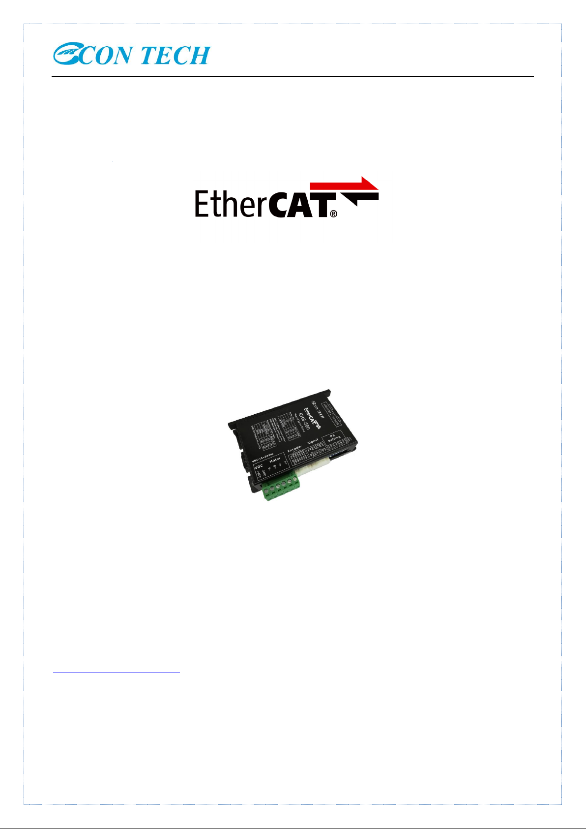
EHS-580
EtherCAT Hybrid Servo Drive
© 2017 shenzhen ECON Technology Co.,Ltd. Version 2.0
Add:2F,BuildingB,Jintai,Industrial,Park,HangchengAvenue,GushuVillage,XixiangStreet,Bao'anArea,ShenzhenCity,
GuangdongProvince,China
Tel: +86 136 2096 1024
E-mail:enquiry@hybridservo.com
technical01@hybridservo.com
All rights reserved
[Please read this manual carefully before use to avoid damage the drive]
Page 2

SHENZHEN ECON TECHNOLOGY CO.,LTD User Manual For EHS-580 EtherCAT Hybrid Servo Drive
Contents
Part 1: EHS-580 .......................................................................................................................................................... 5
Hardware Manual ........................................................................................................................................................ 5
1 Descriptions .............................................................................................................................................................. 5
2 Features .................................................................................................................................................................... 5
3 Applications .............................................................................................................................................................. 5
4 Specifications ............................................................................................................................................................ 6
4.1 Electrical Specifications ................................................................................................................................ 6
4.2 Operating Environment ................................................................................................................................. 6
5 Mechanical Specifications ........................................................................................................................................ 6
6 Connectors and Pin Assignment ............................................................................................................................... 7
6.1 Control signals connector .............................................................................................................................. 7
6.2 Encoder Feedback and hall signal Connector ............................................................................................... 8
6.3 Power and Motor ........................................................................................................................................... 8
6.4 EtherCAT Communication Port ..................................................................................................................... 9
7 DIP Switch Settings ................................................................................................................................................ 10
7.1 E-CAT ID Table ........................................................................................................................................... 10
8 Hybrid servo Motors ................................................................................................................................................ 11
8.1 Nema24 and Nema34motor .......................................................................................................................... 11
8.2 Nema34motor ............................................................................................................................................... 11
9 Wiring Diagrams .................................................................................................................................................... 12
9.1 Interface ....................................................................................................................................................... 12
9.2 Diagram ....................................................................................................................................................... 13
10 Protection Indications ........................................................................................................................................... 13
11 Frequently Asked Questions .................................................................................................................................. 13
Problem Symptoms and Possible Causes........................................................................................................... 14
12 Warranty ............................................................................................................................................................... 14
Exclusions .......................................................................................................................................................... 15
Obtaining Warranty Service .............................................................................................................................. 15
Warranty Limitations ......................................................................................................................................... 15
Part 2 : EHS-580 EtherCAT Communication Protocol Specification ....................................................................... 16
1. Introduction ....................................................................................................................................................... 16
2. Operation mode ................................................................................................................................................. 16
2.1 Profile position mode(PP) ........................................................................................................................... 16
2.1.1 Related objects .................................................................................................................................. 17
2.1.2 Control word and Status word .......................................................................................................... 17
2.1.3 Typical motion mode of bit 5 at PP mode ......................................................................................... 17
2.1.4 The bit 8,10.12-15 of status word ..................................................................................................... 18
2.2 Profile velocity mode (PV ) .......................................................................................................................... 19
2.3 Cyclic synchronous position mode mode(CSP) ........................................................................................... 19
2.3.1 Related objects .................................................................................................................................. 19
2.4 Homing mode (HM) ..................................................................................................................................... 20
3. Input and output ................................................................................................................................................. 22
Page 3

SHENZHEN ECON TECHNOLOGY CO.,LTD User Manual For EHS-580 EtherCAT Hybrid Servo Drive
3.1 Input configuration ................................................................................................................................ 22
3.2 Output configuration ............................................................................................................................. 23
3.3 Related node ID ..................................................................................................................................... 24
3.4 Motor rotation direction setting ............................................................................................................. 24
3.5 Pulse/Revolution setting ........................................................................................................................ 24
4. Parameters ......................................................................................................................................................... 25
4.1 Parameter saving ................................................................................................................................... 25
4.2 Parameter reset ...................................................................................................................................... 25
4.3 Parameters list ....................................................................................................................................... 25
5. Basic Information Of EtherCAT ........................................................................................................................ 29
5.1 EtherCAT Data Frame Structure ................................................................................................................. 29
5.2 Synchronous Mode ....................................................................................................................................... 29
5.2.1 Random running mode ...................................................................................................................... 29
5.2.2 Distributed clock synchronization mode ........................................................................................... 29
5.2.3 EtherCAT state machine ................................................................................................................... 30
5.3 COE ............................................................................................................................................................. 30
5.3.1 Service data object (SDO) ................................................................................................................ 31
5.3.2 SDO protocol and message format ................................................................................................... 31
5.3.3 Suspend SDO transmission ............................................................................................................... 32
5.4 processing data object ................................................................................................................................. 34
5.4.1 PDO mapping ................................................................................................................................... 34
5.4.2 PDO dynamical mapping.................................................................................................................. 35
5.4.3 The difference of PDO and SDO ....................................................................................................... 35
Contact us: ................................................................................................................................................................. 36
Page 4

SHENZHEN ECON TECHNOLOGY CO.,LTD User Manual For EHS-580 EtherCAT Hybrid Servo Drive
EtherCAT :
EtherCAT (Ethernet for Control Automation Technology) is open network communication using
real-time Ethernet between masters and slaves developed by Beckhoff Automation GmbH, Germany.
This User Manual of EHS-580 Included:
Part 1:EHS-580 hardware manual
This part for hardware, function description, parameter configuration, etc.
Part 2 :EHS-580 EtherCAT communication protocol specification
This part for EtherCAT communication protocol.
Notice!
Read this manual carefully before any assembling and using. Incorrect handling of products in this manual can
result in injury and damage to persons and machinery. Strictly adhere to the technical information regarding
installation requirements.
This manual is not for use or disclosure outside of ECON technology except under permission. All rights are
reserved. No part of this manual shall be reproduced, stored in retrieval form, or transmitted by any means,
electronic, mechanical, photocopying, recording, or otherwise without approval from ECON technology. While
every precaution has been taken in the preparation of the book, ECON technology assumes no responsibility for
errors or omissions. Neither is any liability assumed for damages resulting from the use of the information
contained herein.
This document is proprietary information of ECON technology that is furnished for customer use ONLY.
Information in this document is subject to change without notice and does not represent a commitment on the part
of ECON technology. Therefore, information contained in this manual may be updated from time-to-time due to
product improvements, etc., and may not conform in every respect to former issues.
Page 5

SHENZHEN ECON TECHNOLOGY CO.,LTD User Manual For EHS-580 EtherCAT Hybrid Servo Drive
Part 1:EHS-580
Hardware Manual
1 Descriptions
EHS-580 is Econ technology's new EtherCAT hybrid servo driver, which adopt the latest floating-point 64-bit
MCU digital processing technology, the advanced vector control technology drive the motor with low heating ,low
noise and extra smoothly. The user can set any ID address within 1-255 and any current value under the rated
current, it can be matched with different of size motors(from Nema17--Nema24) to applied for variable
applications. the drive can auto-tuning for matching the motor when power up, which can automatically generate
optimal operating parameters for different motors to maximize the performance of the motor
2 Features
New floating point 64bit MCU technology
Serial Port And Auto Tune Function
3 channels opto-coupler isolation OC output
Advanced vector control technology
High torque at starting and low speed
5 channels opto-coupler isolation input,2 of them are high speed opto-coupler isolation input
Communication Frequency up to 100MHz
DIPs can set 127 IPs or automatic allocate IP
Current setting range 0.5-8A
Smooth movement and extra low noise
The supported encoder can be 500ppr—5000ppr.
3 Applications
For a variety of small and medium-sized automation equipment and instruments, such as: AGV, speed pass door,
engraving machine, marking machine, cutting machine, laser Phototypesetting, router machine, plotter, CNC
machine tools, automatic assembly equipment. The users can get special effect from small noise, high speed
equipment application.
Page 6
SHENZHEN ECON TECHNOLOGY CO.,LTD User Manual For EHS-580 EtherCAT Hybrid Servo Drive
Description
EHS-580
Min
Typical
Max
Unit
Output Current(peak)
0.5 - 8.0 A Input Voltage(DC)
15
24/36/48
50
VDC
Control Signal Input Current
6
10
16
mA
Control Signal Interface
Electricity
4.5 5 28
Vdc
OC output Pull-Up voltage
5 - 24
Vdc
Ether-CAT communication
frequency
-
100
-
MHz
Insulation Resistance
100
MΩ
Cooling
Natural Cooling or Forced cooling
Environment
Condition
Far away from other heating device,Avoid dust, oil fog
and corrosive gases, heavy humidity and strong vibration
occasion, forbid flammable gases and conductive dust
Temperature
-10℃~ +50℃
Humidity
40 ~ 90%RH
Vibration
5.9m/s2MAX
Storage Environment
-20℃~60℃
Altitude
Less than 1000m
Weight
about 0.2KG
4 Specifications
4.1 Electrical Specifications
4.2 Operating Environment
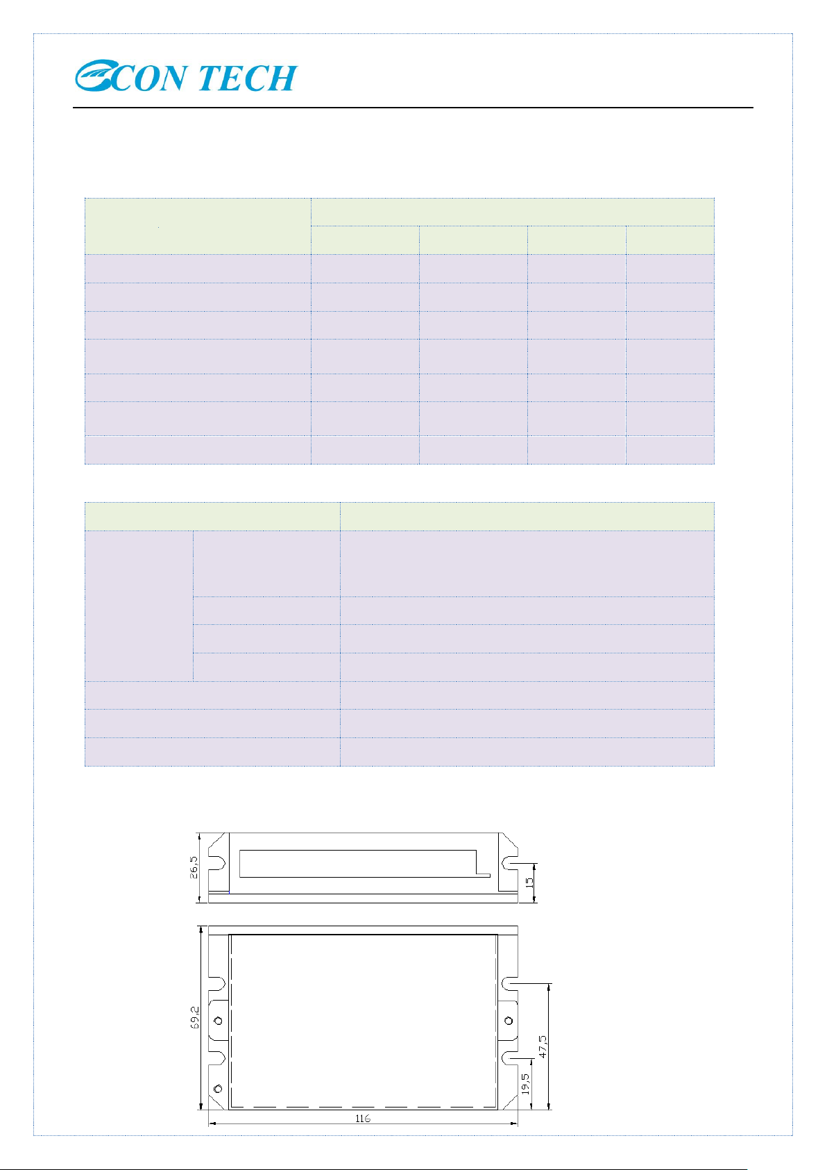
5 Mechanical Specifications
Page 7
SHENZHEN ECON TECHNOLOGY CO.,LTD User Manual For EHS-580 EtherCAT Hybrid Servo Drive
Pin Function
Details
pl+
INEFFECTIVE
pl-
dr+
dr-
in+
Low speed signal:in1,in2,in3 common positive input,5-28VDC
in1
Low speed in1 negative input
in2
Low speed in2 negative input
in3
Low speed in3 negative input
ot-
Common negative OC emitter output,ot1,ot2,ot3 emitter OC output common terminal
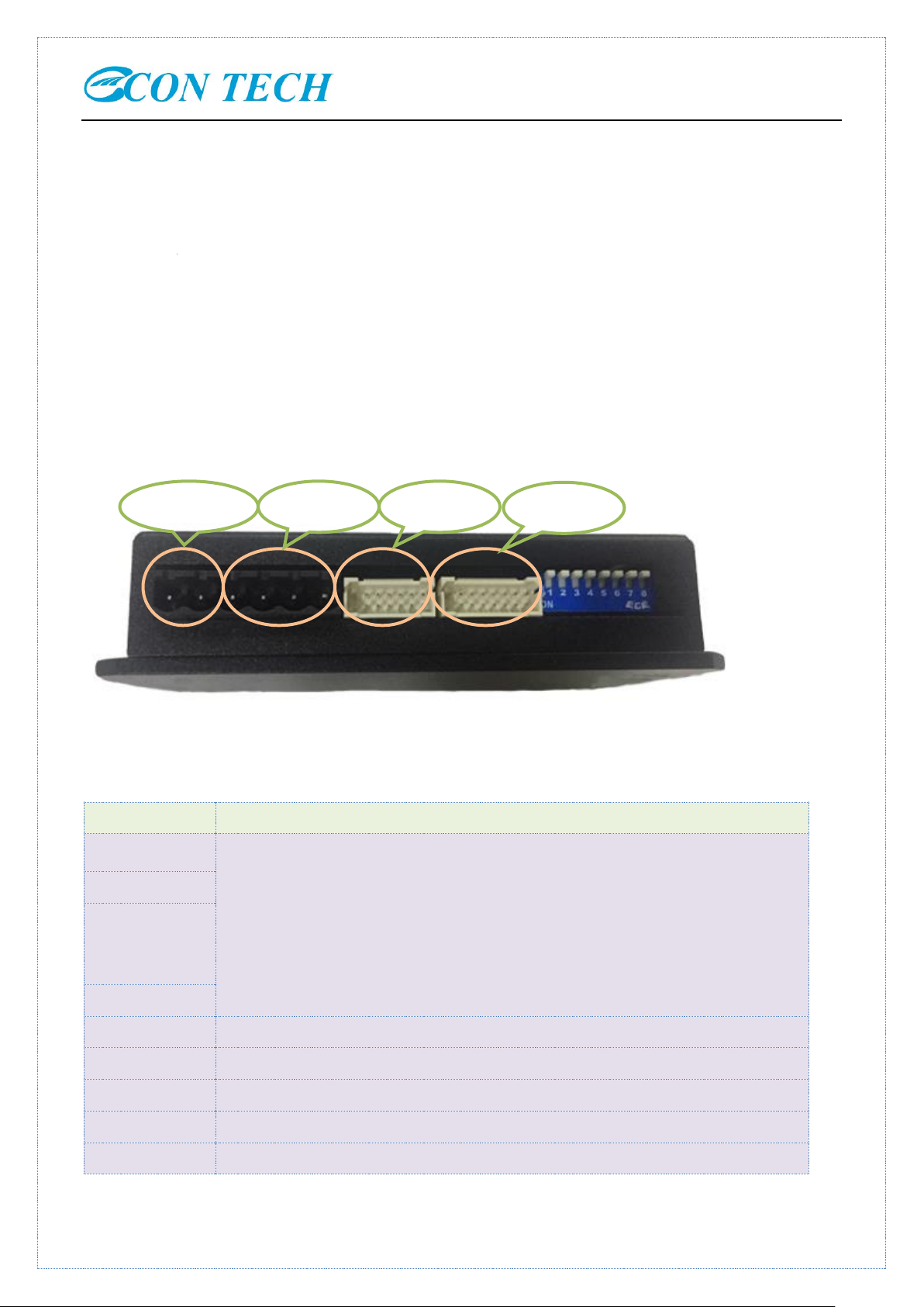
]I/O signal
Encoder
Motor
Power input
※Recommend side installation, better cooling effect, when design installation dimension, consider the terminal
size and wiring!
Enhance Cooling method
A:The driver's reliable operating temperature is usually within 60 ℃, the motor operating temperature is within
80 ℃;
B: It is recommended to use the automatic half-flow mode, the current will be automatically reduced by half when
the motor stops, so as to reduce the heating of the motor and the drive;
C: When installing the driver, please use the vertical side installation, so that the cooling teeth form a strong air
convection; when necessary, install a fan where is close to the drive, forced cooling to ensure that the drive is in a
reliable working temperature range
6 Connectors and Pin Assignment
The EHS-580 has four connectors, connector for i/o connections, connector for Encoder Feedback and hall signal,
connector for power and motor connection, and the CAT Communication Port
6.1 Control signals connector
Page 8

SHENZHEN ECON TECHNOLOGY CO.,LTD User Manual For EHS-580 EtherCAT Hybrid Servo Drive
ot1
ot1emitter output,the Max pull-up voltage 24Vdc,the pull-up resistance 2KΩ,the Max
output current 100mA
ot2
ot2 emitter output,the Max pull-up voltage 24Vdc,the pull-up resistance 2KΩ,the Max
output current 100mA
ot3
ot3 emitter output,the Max pull-up voltage 24Vdc,the pull-up resistance 2KΩ,the Max
output current 100mA
gnd
5V-
RS232-TX
RS232-RX
5V
5V+,current 50mA
Pin Function
Details
ea+
Encoder channel A input
ea-
eb+
Encoder channel B input
eb-
ez+
Encoder channel Z input(if there is Z signal in encoder ,no connection needed )
ez-
eu+
Hall U channel U input, special for dc brushless servo, open loop/hybrid servo no
connection needed
eu-
ev+
Hall V channel U input, special for dc brushless servo, open loop/hybrid servo no
connection needed
ev-
ew+
Hall W channel U input, special for dc brushless servo, open loop/hybrid servo no
connection needed
ew-
5V
Provide 5V+ dc power to motor encoder and Hall components, current 100mA
gnd
5V-
Pin
Definition
I/O
Description
1
A+ O Motor Phase A+
2
A- O Motor Phase A- (U for dc brushless servo motor)
3
B+ O Motor Phase B+ (V for dc brushless servo motor)
4
B- O Motor Phase B- (W for dc brushless servo motor)
5
+VDC
I
15-50VDC,36VDC is recommended, leaving rooms for voltage fluctuation
6.2 Encoder Feedback and hall signal Connector
6.3 Power and Motor
Page 9
SHENZHEN ECON TECHNOLOGY CO.,LTD User Manual For EHS-580 EtherCAT Hybrid Servo Drive
6
GND
GND
and back-EMF.
PIN
Signal
Function Description
1
TX+
Ether CAT data sending positive port
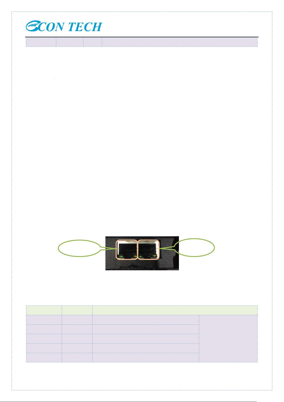
EtherCAT IN(ECAT IN)
2
TX-
Ether CAT data sending negative port
3
RX+
Ether CAT data receiving positive port
4
NC
No connected
5
NC
No connected
ECAT IN
ECAT OUT
Power supply voltage between the provisions of the normal work, EHS-580 driver is best to use non-regulated DC
power supply,can also use the transformer step-down + bridge rectifier + capacitor filter. However, take care that
the peak value of the rectified voltage ripple does not exceed its maximum specified voltage. It is recommended
that users use DC voltage lower than the maximum voltage to supply power and avoid the fluctuation of power grid
beyond the working range of driver voltage.
If you are using a regulated switching power supply, be aware that the output current range of the switching power
supply needs to be maximized.
Please note!
A:When wiring, pay attention to the positive and negative poles of the power supply.
B:Better use non-regulated power supply;
C:When use a non-regulated power supply, the power supply current output capacity should be greater than 60% of
the drive setting current;
D:The use of regulated switching power supply, the output current of the power supply should be greater than or
equal to the working current of the driver;
E:To reduce costs, two or three drives can share a power supply, but should ensure that the power supply is large
enough.
6.4 EtherCAT Communication Port
Two RJ45 terminals
Page 10
SHENZHEN ECON TECHNOLOGY CO.,LTD User Manual For EHS-580 EtherCAT Hybrid Servo Drive
6
RX-
Ether CAT data receiving negative port
7
NC
Disconnect
8
NC
Disconnect
9
TX+
Ether CAT data sending positive
EtherCAT OUT(ECAT
OUT)
10
TX-
Ether CAT data sending negative
11
RX+
Ether CAT data receiving positive
12
NC
No connected
13
NC
No connected
14
RX-
Ether CAT data receiving negative
15
NC
No connected
168
NC
No connected
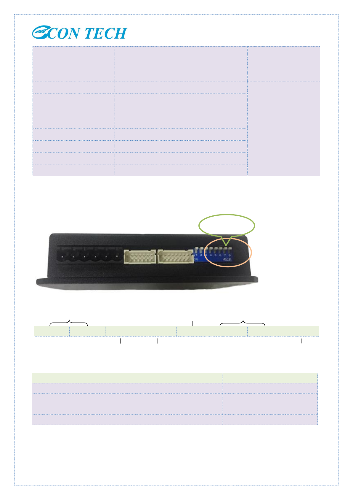
SW1
SW2
SW3
SW4
SW5
SW6
SW7
SW8
Filter Sel
SW6
SW7
Nema11
on
on
Nema17
off
on
Nema23/nema24
on
off
Nema34
off
off
Motor selection
Direction
Filter time setting
Open/closed loop Working mode
Self- test
DIP switch
Note: The cable connecting EHS-580 to PC must be a dedicated cable. Please check before use to avoid damage.
7 DIP Switch Settings
7.1 Motor selection
Page 11

SHENZHEN ECON TECHNOLOGY CO.,LTD User Manual For EHS-580 EtherCAT Hybrid Servo Drive
TC42-03
TC42-04
TC42-06
TC42-08
Step Angle (Degree)
1.8
1.8
1.8
1.8
Holding Torque (N.m)
0.3
0.4
0.6
0.8
Phase Current (A)
2.3
1.68
2.3
2.3
Phase Resistance (Ohm)
0.94
1.65
1.3
1.7
Phase Inductance (mH)
1.8
2.8
2.5
4.6
Inertia (g.cm2)
57
73
86
102
Weight (Kg)
0.24
0.37
0.45
0.5
Encoder (lines / Rev.)
1000
1000
1000
1000
TC57-11
TC57-24(BK)
TC57-28
Step Angle (Degree)
1.8
1.8
1.8
Holding Torque (N.m)
1.1
2.4
2.8
Phase Current (A)
6.0
5.6
5.6
Phase Resistance (Ohm)
0.2
0.4
0.5
Phase Inductance (mH)
0.52
1.5
2.0
Inertia (g.cm2)
300
480
550
Weight (Kg)
0.7
1.1
1.8
Encoder (lines / Rev.)
1000
1000
1000
TC60-15
TC60-30
TC60-40
Step Angle (Degree)
1.8
1.8
1.8
Holding Torque (N.m)
1.5
3.0
4.0
Phase Current (A)
6.0
6.0
5.6
Phase Resistance (Ohm)
0.3
0.6
0.5
Phase Inductance (mH)
1.1
1.8
2.1
Inertia (g.cm2)
400
840
840
8 Hybrid servo Motors
EHS-580 can work with the following ECON technology’s hybrid servo motors:
8.1 Nema17
8.1 Nema23
BK:the motor supports brake
8.3 Nema24 motor
Page 12

SHENZHEN ECON TECHNOLOGY CO.,LTD User Manual For EHS-580 EtherCAT Hybrid Servo Drive
Weight (Kg)
0.8
1.4
1.6
Encoder (lines / Rev.)
1000
1000
1000
TC86-45
TC86-85
TC86-120
Step Angle (Degree)
1.8
1.8
1.8
Holding Torque (N.m)
4.5
8.5
12
Phase Current (A)
6.0
6.0
6.0
Phase Resistance (Ohm)
0.325
0.5
0.73
Phase Inductance (mH)
3.0
6.0
8.68
Inertia (g.cm2)
1400
2700
4000
Weight (Kg)
2.3
3.8
5.3
Encoder (lines / Rev.)
1000
1000
1000
8.4 Nema34 hybrid servo motor
Note: All motors can make brake
9 Wiring Diagrams
9.1 Interface
Page 13

SHENZHEN ECON TECHNOLOGY CO.,LTD User Manual For EHS-580 EtherCAT Hybrid Servo Drive
Flashes Times
Red LED flash wave
Fault Description
1
over-current or phase short-circuit fault
2
over-voltage fault
3
under-voltage fault
7
over-error alarm
9
phase fault or current collecting fault
9.2 Diagram
10 Protection Indications
The green indicator turns on when power-up. When drive protection is activated, the red LED blinks periodicity to
indicate the error type.
A:Over current or phase Short circuit protection
When a short circuit occurs or the internal drive over-current, the drive RED Led flashes 1 time, and repeat flashing
within 3 seconds. At this point must discharge fault, re-power and reset.
B: Over-voltage protection
When input voltage is higher than 55V, the driver RED Led flashes twice, and flashes repeatedly within 3 seconds.
At this point must discharge fault, re-power and reset.
△ Note! Since the drive does not have the power supply reverse polarity protection function, therefore,
before power on, make sure the positive and negative power supply wiring is correct. Reverse polarity will
lead to burn the fuse in the drive!
11 Frequently Asked Questions
In the event that your drive doesn’t operate properly, the first step is to identify whether the problem is electrical or
Page 14

SHENZHEN ECON TECHNOLOGY CO.,LTD User Manual For EHS-580 EtherCAT Hybrid Servo Drive
Problem
Possible Reason
Solution
Motor is not rotating
Power supply light is off
check power supply line, keep power supply
normal
motor shaft disabled
Pulse signal weak, increase signal current to
7-16mA
Micro-step too small
select the suitable micro-step
current setting is too small
Select the correct current
drive protected
Reboot
Enable signal too low
Pull up enable signal or disconnect
no action to control signal
Check the power supply input
Wrong motor motion
Motor cable incorrect
connect
Change any two cables of same phase(such as
A+/A- change)
Motor cable has breakage
Check and correct wiring connection
The drive In alarm
motor cable incorrect
connect
Check wiring
over-voltage or
under-voltage
Check power supply
motor or drive damaged
Replace a motor or drive
Position inaccurate
signal is interfered
Exclude interference
Shield ground disconnect or
bad connect
Reliable ground connection
Motor cable has breakage
Check and correct wiring connection
Wrong micro-step
Set correct micro-step
Current small
Increase current
Motor stall when
speed increase
Acceleration time is too
short
Increase acceleration time
Motor torque is too small
Select big torque motor
Voltage is low or current is
small
Suitable increase voltage and current
mechanical in nature. The next step is to isolate the system component that is causing the problem.As part of this
process you may have to disconnect the individual components that make up your system and verify that they
operate independently. It is important to document each step in the troubleshooting process. You may need this
documentation to refer back to at a later date, and these details will greatly assist our Technical Support staff in
determining the problem should you need assistance.
Many of the problems that affect motion control systems can be traced to electrical noise, controller software errors,
or mistake in wiring.
Problem Symptoms and Possible Causes
12 Warranty
Shenzhen ECON Technology Co., Ltd. warrants its products against defects in materials and workmanship for a
Page 15

SHENZHEN ECON TECHNOLOGY CO.,LTD User Manual For EHS-580 EtherCAT Hybrid Servo Drive
period of 12 months from shipment out of factory. During the warranty period, ECON technology will either, at its
option, repair or replace products which proved to be defective.
Exclusions
The above warranty does not extend to any product damaged by reasons of improper or inadequate handlings by
customer, improper or inadequate customer wirings, unauthorized modification or misuse, or operation beyond the
electrical specifications of the product and/or operation beyond environmental specifications for the product.
Obtaining Warranty Service
To obtain warranty service, a returned material authorization number (RMA) must be obtained from customer
service at e-mail: technical01@hybridservo.com before returning product for service. Customer shall prepay
shipping charges for products returned to ECON technology for warranty service, and ECON technology shall pay
for return of products to customer.
Warranty Limitations
ECON technology makes no other warranty, either expressed or implied, with respect to the product. ECON
technology specifically disclaims the implied warranties of merchantability and fitness for a particular purpose.
Some jurisdictions do not allow limitations on how long and implied warranty lasts, so the above limitation or
exclusion may not apply to you. However, any implied warranty of merchantability or fitness is limited to the
12-month duration of this written warranty.
Page 16

SHENZHEN ECON TECHNOLOGY CO.,LTD User Manual For EHS-580 EtherCAT Hybrid Servo Drive
Command input type
Variable
Operation mode
BUS command input
Address 6060H=1
PP mode
Address 6060H=3
PV mode
Address 6060H=6
HM mode
Address 6060H=8
CSP mode
Part
2 :EHS-580
EtherCAT Communication Protocol
Specification
1. Introduction
EHS-580 is a new released EtherCAT hybrid servo drive , which support CANopen over EtherCAT (CoE) control
and CiA 402 operating modes ,including Profile Position (PP), Profile Velocity (PV), Homing (HM) and Cyclic
Synchronous Position (CSP). This drive is compatible with many EtherCAT controller/PLC ,such as Beckhoff,
Omron, etc. its excellent performance can meet many applications with extra low noise, low heating and super
smoothness.
2. Operation mode
A: PP mode:profile position mode
B: PV mode:Profile velocity mode
C: HM mode:Homing mode
D: CSP mode:Cyclic synchronous position mode
2.1 Profile position mode(PP)
Profile Position control mode is general point to point operation, to move to target position of Target position
(607Ah) object with receipt of Control word (6040h) input, need to set Profile Position Mode at operation mode
object (6060h). The Operation Mode Display object (606lh) is shown as Profile Position Mode.
Page 17

SHENZHEN ECON TECHNOLOGY CO.,LTD User Manual For EHS-580 EtherCAT Hybrid Servo Drive
Data write/read
Object
Description
Value
Unit
RXPDO
6060h
Operation Mode
1
-
6040h
Control word
User self-defined
-
607Ah
Target Position
User self-defined
Unit
6081h
Maximum speed
User self-defined
Unit/s
6082h
Start /Stop speed
User self-defined
Unit/S^2
6083h
Profile Acceleration
User self-defined
Unit/S^2
6084h
Profile Deceleration
User self-defined
Unit/S^2
6085h
Emergency stop deceleration, base
on the value of 605Ah
User self-defined
Unit/S^2
605Ah
Enable the deceleration of E-stop(5:
enable; Others: disable)
User self-defined
-
2000h
Revolution per round
User self-defined
pulse
TXPDO
6041h
Status word
Read only
-
6064h
Actually position Feedback
Read only
Unit
606Ch
Actual velocity feedback
Read only
Unit/s
603Fh
Error code
Read only
-
6061h
Operation mode display
Read only
-
Bit
Value
Description
4(new position)
0 —> 1
The motor run with the max speed(6081h) and
Acc(6083h )/Dec(6084h) to latest target position(607Ah)
5((trigger immediately)
0
Trigger the new movement after the current movement is
completed
1
Interrupt the current movement immediately, and start the
new movement
6 (absolutely /relatively)
0
Process target position(607Ah) as the absolutely position
1
Process target position(607Ah) as the relatively position
Bit 5
0
1
2.1.1 Related objects
2.1.2 Control word and Status word
In PP Mode, the bits 4~6 of Control word (6040h)
2.1.3Typical motion mode of bit 5 at PP mode
Page 18

SHENZHEN ECON TECHNOLOGY CO.,LTD User Manual For EHS-580 EtherCAT Hybrid Servo Drive
Forward movement to updated
target position with Acc/constant
speed
Forward movement to updated
target position with Dec
Backward movement to updated
target position
Bit
Value
Description
8 (abnormal stop)
0
Normal movement
1
Trigger by abnormal stop, motor will stop
10 (position reached)
0
Movement is continue
1
target position reached
12 (new position
response)
0
When current movement is completed or interruptable, can update new target
position
1
When current motion uncompleted/uninterruptable, it can not update new target
position
14(parameters value
for movement are 0)
0
Parameters for movement are effective, and all necessary parameters are not 0
1
One of parameters( max speed-6081h, acceleration-6083h) and deceleration
--6084h)must be 0
15 (Trigger
response)
0
When current movement is not completed or not interruptable,can not update
new target position
1
When current movement is completed or interruptable, can update new target
position
A:Command change time of master
B:Arrived time to the target position(before updated)
C:Arrived time to the target position(after updated)
2.1.4 The bit 8,10.12-15 of status word
A: Bit8 abnormal stop is effective at the triggered status for hardware limit switch, deceleration stop and
emergency stop
B:Bit 12 of Status word (6041h) will clear to 0 when the bit 5 of control word (6040h) is triggered and bit 4 of
Page 19

SHENZHEN ECON TECHNOLOGY CO.,LTD User Manual For EHS-580 EtherCAT Hybrid Servo Drive
Data write/read
Object
Description
Value
Unit
RXPDO
6060h
Operation Mode
1
-
6040h
Control word
User self-defined
-
60FFh
Target Position
User self-defined
Unit
6083+00h
Profile Acceleration
User self-defined
Unit/S^2
6084+00h
Profile Deceleration
User self-defined
Unit/S^2
TXPDO
6041h
Status word
Read only
-
6064h
Actually position Feedback
Read only
Unit
606Ch
Actual velocity feedback
Read only
Unit/s
Bit
Value
Description
8(quickly stop)
0
Quickly stop is disabled
1
Quickly stop is enabled
10(speed reached)
0
The current speed has not reach to target speed
1
The current speed reach to target speed
12 (speed is 0)
0
Speed is not 0 , the movement is not completed
1
Speed is 0 or the speed is ready to be 0 with Dec
Data write/read
Object
Description
Value
Unit
6060h
Operation Mode
1
-
(6040h) is invalid triggered (for example 6040h = 0x2F/4F), it can be interrupted
C: The logic of bit 5 and bit 12 is always reverse in PP mode.
2.2 Profile velocity mode(PV )
Profile velocity mode is a relatively simple operating mode via execution related command sending by EtherCAT
master
2.2.1Controlword and Status word
In PV Mode, bits 4~6of Control word (6040h) are not effective, the movement will be active by setting some
movement parameters, including target velocity (60FFh), acceleration/deceleration (6083h/6084h).
2.3Cyclic synchronous position mode(CSP)
Cyclic Synchronous Position mode (CSP Mode) assigns target position to EHS-580hybrid servo drives by Master's
profile creation function through cyclic communication. Drives internally execute position/velocity control with
receipt of target position in each cycle.
The supported synchronizing cycles are: 250us, 500us, 750us, 1000us, 2000us and 4000us.
2.3.1 Related objects
Page 20

SHENZHEN ECON TECHNOLOGY CO.,LTD User Manual For EHS-580 EtherCAT Hybrid Servo Drive
RXPDO
6040h
Control word
User self-defined
-
607Ah
Target Position
User self-defined
Unit
60B0h
Maximum speed
User self-defined
Unit/s
2000h
Revolution per round
User self-defined
pulse
TXPDO
6041h
Status word
Read only
-
6064h
Actually position Feedback
Read only
Unit
606Ch
Actual velocity feedback
Read only
Unit/s
603Fh
Error code
Read only
-
6061h
Operation mode display
Read only
-
Data write/read
Object
Description
Value
Unit
RXPDO
6060h
Operation Mode
1
-
6040h
Control word
User self-defined
-
607Ah
Target Position
User self-defined
Unit
6081h
Maximum speed
User self-defined
Unit/s
6082h
Start /Stop speed
User self-defined
Unit/S^2
6083h
Profile Acceleration
User self-defined
Unit/S^2
6084h
Profile Deceleration
User self-defined
Unit/S^2
6085h
Emergency stop deceleration, base
on the value of 605Ah
User self-defined
Unit/S^2
605Ah
Enable the deceleration of E-stop(5:
enable; Others: disable)
User self-defined
-
2000h
Revolution per round
User self-defined
pulse
TXPDO
6041h
Status word
Read only
-
6064h
Actually position Feedback
Read only
Unit
606Ch
Actual velocity feedback
Read only
Unit/s
603Fh
Error code
Read only
-
6061h
Operation mode display
Read only
-
2.4 Homing mode(HM)
Homing mode is the way of detecting the home point with command of Control word (6040h). 6060h is address for
homing Mode enable/disable. And will execute the command once Mode of operation display (6061h) indicates
Homing Mode.
2.4.1 Related objects
2.4.2 The bits 4~6 of Control word (6040h)
Page 21

SHENZHEN ECON TECHNOLOGY CO.,LTD User Manual For EHS-580 EtherCAT Hybrid Servo Drive
Bit
Value
Description
4(new position)
0 —> 1
The motor run with the max speed(6081h) and
Acc(6083h )/Dec(6084h) to latest target position(607Ah)
5((trigger immediately)
0
Trigger the new movement after the current movement is
completed
1
Interrupt the current movement immediately, and start the
new movement
6 (absolutely /relatively)
0
Process target position(607Ah) as the absolutely position
1
Process target position(607Ah) as the relatively position
Bit
Value
Description
8 (abnormal stop)
0
Normal movement
1
Trigger by abnormal stop, motor will stop
10 (position reached)
0
Movement is continue
1
target position reached
12 (new position
response)
0
When current movement is completed or interruptable, can update new target
position
1
When current motion uncompleted/uninterruptable, it can not update new target
position
14(parameters value
for movement are 0)
0
Parameters for movement are effective, and all necessary parameters are not 0
1
One of parameters( max speed-6081h, acceleration-6083h) and deceleration
--6084h)must be 0
15 (Trigger
response)
0
When current movement is not completed or not interruptable,can not update
new target position
1
When current movement is completed or interruptable, can update new target
position
2.4.3 The bit 8,10.12-15 of status word
A: Bit8 abnormal stop is effective at the triggered status for hardware limit switch, deceleration stop and
emergency stop
B:Bit 12 of Status word (6041h) will clear to 0 when the bit 5 of control word (6040h) is triggered and bit 4 of
(6040h) is invalid triggered (for example 6040h = 0x2F/4F), it can be interrupted
C: The logic of bit 5 and bit 12 is always reverse in PP mode.
Page 22

SHENZHEN ECON TECHNOLOGY CO.,LTD User Manual For EHS-580 EtherCAT Hybrid Servo Drive
Address
Definition
Default
value
Range
Description
2152+01
Input 1
R/W/S
1
0—32768
1:homing
2:limit4:limit+
2152+02
Input 2
R/W/S
2
0—32768
1:homing
2:limit4:limit+
2152+03
Input 3
R/W/S
4
0—32768
1:homing
2:limit4:limit+
2152+04
Input 4
R/W/S
8
0—32768
1:homing
2:limit4:limit+
2152+05
Input 5
R/W/S
0
0—32768
1:homing
2:limit4:limit+
2153+01
Filter time for Input1
R/W/S
20
1—60000
Unit:50us
2153+02
Filter time for Input2
R/W/S
20
1—60000
Unit:50us
2153+03
Filter time for Input3
R/W/S
20
1—60000
Unit:50us
2153+04
Filter time for Input4
R/W/S
20
1—60000
Unit:50us
2153+05
Filter time for Input5
R/W/S
20
1—60000
Unit:50us
Input connector
Output connector
3. Input and output
3.1 Input configuration
The IN1~IN3 are single end input ports(The power supply from host Controller/PLC/motion Control card should
be 12-24VDC, current ≥ 100mA), pl+,pl-,dr+,dr- are high speed differential pulse input ports.
Page 23

SHENZHEN ECON TECHNOLOGY CO.,LTD User Manual For EHS-580 EtherCAT Hybrid Servo Drive
2154+00
Logic configuration for
inputs
R/W/S 0 0/1
0:Positive logic
1:negative logic
bit0: input1 polarity setting
bit1: input2 polarity setting
bit2: input3 polarity setting
bit3: input4 polarity setting
bit4: input5 polarity setting
2155+00
Level configuration for
inputs
R 0
0/1
0:Low level
1:High level
bit0: input1 polarity setting
bit1: input2 polarity setting
bit2: input3 polarity setting
bit3: input4 polarity setting
bit4: input5 polarity setting
Address
Definition
Description
60FD+00
Input status
R
bit0:limit-
bit1:limit+
bit2:homing
Address
Definition
Default value
Range
Description
2005+01
Output1
R/W/S 1 1—4
bit0:Alarm output
bit1:Ready output
Bit2: Pend output
2005+02
Output 2
R/W/S 1 1—4
bit0:Alarm output
bit1:Ready output
Bit2: Pend output
IO Status display
3.2 Output configuration
A:The power supply for outputs is 12-24VDC, and if power supply is wrong wiring, it is a risk to burnt the drive
B: It is OC output with the maximum capacity of 50mA/25V, it is recommended to connect a resistor to power
supply(1K Ohm for 12VDC ,2K Ohm for 24VDC)
C:If the output is a relay, it is recommended to connect a freewheel diode with inverse parallel connection to relay
for protection the drive
Page 24

SHENZHEN ECON TECHNOLOGY CO.,LTD User Manual For EHS-580 EtherCAT Hybrid Servo Drive
2008+00
Output level
R/W/S 0 0/1
0:Low level
1:High level
bit0 :out1
bit1: out2
Address
Definition
Default value
Range
Description
2150+00
Slave address
R/W/S
1
1—65535
Slave address
2151+00
Salve address
resource
R/W/S 0
0~2
0:From DIP switch,when the DIP setting
is 0, it is from EEPROM.
1:From 2150h
Address
Definition
Default value
Range
Description
2051+00
Motor rotation
direction
R/W/S 0 0/1
0:no change for motor rotation direction
1:reversed motor rotation direction
Address
Definition
Default value
Range
Description
2001+00
Pulse/Revolution
R/W/S
50000
200—51200
Pulse for per revolution
3.3 Related node ID
The master can scan the node address automatically ,and it also can be set by manual
3.3.1 DIP switch setting
When the 2151h value is 0,the user can set the slave address by DIP switch(it is effective only after restarting drive)
3.3.2Reading the ID alias of ESC
The EtherCAT master can configure ID alias to the EEPROM 0004h of ESC, when the 2051h is 0, and the address
setting via DIP switches is 0, the value at address 0004h will be the ID alias of the slave after the power supply
restarted.
3.3.3 Setting the ID alias via object dictionary
If the 2151h is 1,the value of 2150h will be the ID alias after the power supply restarted.
3.4 Motor rotation direction setting
The motor rotation direction can be set by command from master
3.5 Pulse/Revolution setting
Page 25

SHENZHEN ECON TECHNOLOGY CO.,LTD User Manual For EHS-580 EtherCAT Hybrid Servo Drive
Address
Definition
Default
value
Range
Description
2000+00
Peak current
R/W/S
3200
1 to the max
current
Output current(mA)。
2001+00
Pulse/revolution
R/W/S
50000
200—51200
Pulse for per revolution
(pulse)
2002+00
Stand-by time
R/W/S
500
100—10000
Unit:ms
2005+01
Output1
R/W/S 1 1—4
bit0:Alarm output
bit1:Ready output
Bit2: Pend output
2005+02
Output 2
R/W/S 1 1—4
bit0:Alarm output
bit1:Ready output
Bit2: Pend output
2008+00
Output level
R/W/S 0 0/1
0:Low level
1:High level
bit0 :out1
2009+00
Pulse filter time
enable/disable
R/W/S 0 0/1
0:Disable
1:Enable
2010+02
Filter time
R/W/S
1000
50—25600
Unit:us
4. Parameters
4.1 Parameter saving
The master save the parameters to EEPROM via 0x1010-04 written. When the drive detect the value of
0x1010-04 from master is 0x65766173, the drive will save parameters to EEPROM.
Note! During the EEPROM written operation , please don’t cut off power supply of drive , otherwise cause the
wrong data written
4.2 Parameter reset
The master reset the parameters to default value via 0x1010-04 written. When the drive detect the value of
0x1010-04 from master is 0x64616f6c,all parameter will be reset to default value .
4.3 Parameters list
4.3.1 General parameter list
Page 26

SHENZHEN ECON TECHNOLOGY CO.,LTD User Manual For EHS-580 EtherCAT Hybrid Servo Drive
2013+00
Current loop KP,KI
auto tuning
enable/disable
R/W/S 1 0/1
Auto tuning the Current loop
KP,KI when power up
0:disable 1:enable
2015+00
Current Kp
R/W/S
1000
200—
32767
When the 2013+00 is 1(enable),
this parameter read only
2016+00
Current Ki
R/W/S
200
0—32767
When the 2016+00 is 1(enable),
this parameter read only
2017+00
Current Kc
R/W/S
100
80—300
Read only
2020+00
Motor resistor
R/W/S
1000
1—20000
Unit:mOhms
2021+00
Motor inductance
R/W/S
1
1—6000
Unit:uH
2024+00
Open/closed mode
R/W/S 2 0~2
1:open loop mode
2:closed loop mode
2025+00
Control mode
R/W/S 5 0—10
0:DIP switch
1:Lead2:PM
3:FOC
4:self- test
5:CL
2026+00
Current for shaft
locking
R/W/S
50
0—100
Unit:%,Effective at open loop
mode only
2029+00
Encoder resolution
R/W/S
1000
200—60000
p/r
2030+00
Position following
error
R/W/S
1000
1—60000
pulse
2039+00
Pulse amount H
R 0 0~65535
The received pulse amount H
(16bit)
2040+00
Pulse amount L
R/W 0 0~65535
The received pulse amount16bit
write:write1to clear counter
2041+00
Encoder feedback
amount H
R 0 0~65535
The received encoder feedback
pulse amount H(16bit)
2042+00
Encoder feedback
amount H
R 0 0~65535
The received encoder feedback
pulse amount L(16bit)
write:write 1 to clear counter
2051+00
Motor rotation
direction
R/W/S 0 0/1
0:no change for the rotation
direction
1:reversed rotation direction
2053+00
Pend output
R/W/S 0 0~1
0:low level
1:high level
Page 27

SHENZHEN ECON TECHNOLOGY CO.,LTD User Manual For EHS-580 EtherCAT Hybrid Servo Drive
2056+00
Fault detecting
selection
R/W/S
0xc3
0—0xffff
2057+00
Fault clear
enable/disable
R/W/S 0 0/1
0:Disable
1:Enable
2058+00
Current soft-start time
for shaft enable
R/W/S
1
0—10000
For reducing the vibration when
power up or motor shaft enable
Unit:50us
2083+00
Shaft right left wiggle
when power up
enable/disable
R/W/S 0 0/1
0:Disable
1:Enable
2137+00
Position loop KP
R/W/S
120
0~150
-
2138+00
Position loop KI
R/W/S
50
0~150
-
2139+00
Position loop KVFF
R/W/S
70
0~150
-
2140+00
Speed loop KP
R/W/S
60
0~150
-
2150+00
Slave ID
R/W/S
1
1—65535
Slave address
2151+00
Slave ID resource
R/W/S
0
0~2
0:from DIP switch , when DIP
switch is 0,it is from EEPROM.
1:from2150h
2152+01
Input 1
R/W/S
1
0—32768
1:homing
2:limit4:limit+
2152+02
Input 2
R/W/S
2
0—32768
1:homing
2:limit-
2152+03
Input 3
R/W/S
4
0—32768
1:homing
2:limit-
2152+04
Input 4
R/W/S
8
0—32768
1:homing
2:limit-
2152+05
Input 5
R/W/S
0
0—32768
1:homing
2:limit-
2153+01
Filter time for Input1
R/W/S
20
1—60000
Unit:50us
2153+02
Filter time for Input2
R/W/S
20
1—60000
Unit:50us
2153+03
Filter time for Input3
R/W/S
20
1—60000
Unit:50us
2153+04
Filter time for Input4
R/W/S
20
1—60000
Unit:50us
2153+05
Filter time for Input5
R/W/S
20
1—60000
Unit:50us
Page 28

SHENZHEN ECON TECHNOLOGY CO.,LTD User Manual For EHS-580 EtherCAT Hybrid Servo Drive
2154+00
Logic configuration for
inputs
R/W/S
0
0/1
0:Positive logic
1:negative logic
bit0:input1 polarity
setting
bit1: input2 polarity
2155+00
Level configuration for
inputs
R 0
0/1
0:Low level
1:High level
bit0: input1 polarity
setting
bit1: input2 polarity
setting
bit2: input3 polarity
setting
bit3: input4 polarity
setting
bit4: input5 polarity
setting
2093+00
Record for fault clear
R/W
Address
Definition
Description
6040+00
Control word
R/W
Control word
6041+00
Status word
R
Status word
6060+00
Operation mode
RW
1—PP mode
3—PV mode
6—HM mode
8-CSP mode
6061+00
Mode display R Display the operation mode
6062+00
Command position
R
Display the motor command position
6064+00
Actual position
R
Display the motor actual position
606B+00
Command speed
R
Display motor command speed
606C+00
Actual speed
R/W
Display the motor actual speed Unit:RPM
607A+00
Target position
R/W
The target position at PP mode,if the control word setting for
movement start, it will be changed to valid command position
607C+00
Homing offset
R/W
Homing offset
6081+00
Trapezoidal speed-
R/W
The max trapezoidal speed at PP mode
4.3.2 Operation mode control parameter list
Page 29

SHENZHEN ECON TECHNOLOGY CO.,LTD User Manual For EHS-580 EtherCAT Hybrid Servo Drive
6082+00
Start-stop speed
R/W
The start and stop speed at PP mode
6083+00
Trapezoidal Acc
R/W
Trapezoidal Acc
6084+00
Trapezoidal Dec
R/W
Trapezoidal Dec
6085+00
Dec for E-stop
R/W
Dec for E-stop,it is enabled or disabled depend on the value of
6098+00
Homing research mode
R/W
Homing research mode
6099+01
Homing research speed
R/W
Speed for researching limit switch
6099+02
Homing research speed
R/W
Speed for researching homing
609A+00
Homing research Acc
R/W
Acc of Homing research
60F4+00
Position following error R Position following error
60FD+00
Input status
R
bit0:limit-,bit1:limit+,bit2:homing
60FF+00
Target speed
R/W
The max speed at PV mode
Frame structure
Definition
Target address
MAC address of Receiver
Source address
MAC address of Sender
EtherCAT frame header: data length
EtherCAT the total length of all sub messages in the data field
EtherCAT frame header type
1: communication with slave stations; others are reserved
FCS
The Frame check
5. Basic Information Of EtherCAT
5.1EtherCATData Frame Structure
EtherCAT transmit the data with the network data frame; the fixed frame type is 0x88A4. It includes two bytes of
EtherCAT frame header and 44~1498 bytes of EtherCAT data. The EtherCAT data field consists of one or some
EtherCAT sub messages, each message is corresponding to a storage area of the slave station.
5.2 Synchronous Mode
5.2.1 Random running mode
At this mode, the drive adopt asynchronous mode to process the processing data from master, it is suitable for
asynchronous operation mode only, such as HM mode, PP mode.
5.2.2 Distributed clock synchronization mode
After the master sending the processing data , the slave station receive and read the processing data immediately, at
Page 30

SHENZHEN ECON TECHNOLOGY CO.,LTD User Manual For EHS-580 EtherCAT Hybrid Servo Drive
Communicationfunction
In it
Communication between master and slave stations
Pre-Operation
Mail communication is effective, and no processing data communication, means SDO
function is effective
Safe-Operation
Mail communication and processing data objects sending are effective, means SDO and
TX PDO are effective
Operation
Mail communication, processing data receiving and are is effective, means SDO, RX PDO
and TXPDO are effective
the same time ,it wait the Synchronous signal to trigger the processing data and effect to drive
The processing data must reach drive earlier than SYNC0 T1,and the drive must compete all Analysis of data and
related control algorithm. after receiving SYNC0,drive send the control command immediately. This mode is very
good for data Synchronization
5.2.3 EtherCAT state machine
EtherCAT state machine, commonly called as "communication state machine.it mainly manage the communication
between master and slave .this communication function includes the communication for mail and processing data.
EtherCAT state machine transmission blow chart
The transmission of the EtherCAT state machine features:
A:From initialization to operation, it must follow the sequence(low--high)strictly: you must switch from low to
high ,such as initialization→pre-operation→Safe-operation→operation
B:From high to low transmission, it can be skipped .
C:The master is the sender for all state transmission, the slave must response all request from master
D:If the request from master is failed ,the slave will feedback error to master
5.3 COE
COE is similar as CANopen DS301,but basic on CANopen DS301 , the COE has some changes and extension, the
main difference as below chart
Page 31

SHENZHEN ECON TECHNOLOGY CO.,LTD User Manual For EHS-580 EtherCAT Hybrid Servo Drive
Items
COE
DS301
Fieldbus
EtherCAT
CAN
Message structure
Standard Ethernet
CAN 2.0Astandard
SDO data collection
SM mailbox data area
CAN message
PDO data collection
SM processing data area
CAN message
The length for Each PDO mapping
Maximum 32 bytes
Maximum 8bytes
Communication state machine
0x120/0x130 register
NMT (network management tool)
Identification of communication
Synchronization management
COB-ID (object dictionary identification
5.3.1 Service data object (SDO)
EHS-580 hybrid servo drive supports SDO function, the EtherCAT master can write/read the object dictionary of
drive ,and configure ,monitor, control the drive by SDO.
The SDO is the user/server mode, the master is corresponds to the user in the SDO operation, and
The drive is a server, all of transmission/command must be from master to user.
At the CANopen DS301 mode, the SDO protocol can transmit 8 bytes one time in order to match the
data length of CAN packets. at the COE enhancement mode, it expand the payload data only, and don’t change the
protocol header. In this way, the SDO can use the larger mailbox, and improve the efficiency of data transmission.
5.3.2 SDO protocol and message format
Here are two SDO service supported by EHS-580 hybrid servo drive
A:Fast transmission service: it is same as CANopen DS301,use 8 bytes only to transmit 4 bytes of valid data
B:Conventional transmission service: the max bytes of transmission data depend on the capacity of mail box
manager.
SDO download service format as below chart
The details table for transmission requested service data of SDO downloading
Page 32

SHENZHEN ECON TECHNOLOGY CO.,LTD User Manual For EHS-580 EtherCAT Hybrid Servo Drive
Data area
Bytes
Bit
Definition
Description
Mail header
2
16
Length n
n≥0x0A,COE command and length of SDO data
2
16
Address
Data resource address
1
0~5
Channel
Reserved
6~7
Priority grade
0: lowest priority
1
0~3
Type
3: COE
4~7
Reserved
COE
command
2
0~8
PDO code
0
9~11
Reserved
12~15
Service type
2: SDO request
SDO data
1(control
byte)
0
Quantity mark
0: Not set;
1: Set byte of transmission
1
Transmission
0:conventional/segment
2~3
Byte
transmission
0:conventional/segment transmission invalid;
others: number of byte transmission
4
Completed visit
0: incomplete visit;
1: complete visit
5~7
Command code
0:segment download request
1: download request
2
16
Index
Object dictionary index
1 8 Sub-index
Object dictionary sub-index
4
32
Data
Fast transmission: specified object dictionary data
Conventional transmission: total bytes of object dictionary
n-10
Extended data
Conventional transmission for extended data
Data area
Bytes
Bit
Definition
Description
Mail header
2
16
Length n
n≥0x0A,COE command and length of SDO data
2
16
Address
Data resource address
1
0~5
Channel
Reserved
6~7
Priority grade
0: lowest priority
1
0~3
Type
3: COE
5.3.3SuspendSDO transmission
If it occurs error for data analysis during SDO transmission, the request for suspending SDO transmission can be
sent to master, and receiving the request, SDO transmission is suspended immediately
Suspend SDO transmission chart
Page 33

SHENZHEN ECON TECHNOLOGY CO.,LTD User Manual For EHS-580 EtherCAT Hybrid Servo Drive
4~7
Reserved
COE
command
2
0~8
PDO code
0
9~11
Reserved
12~15
Service type
2: SDO request
SDO data
1(control
byte)
0
Quantity mark
0
1
Transmission
0:conventional/segment
2~3
Byte
transmission
0
4
Reserved
5~7
Command code
4:Terminate SDO transmission request
2
16
Index
Object dictionary index
1 8 Sub-index
Object dictionary sub-index
4
32
suspend code
Details refer to the suspend code chart
Termination code
Meanings
0x05040000
SDO transmission timeout
0x05040001
Command code is invalid or unknown
0x05040005
Memory overflow
0x06010000
An attempt to manipulate objects that do not support access
0x06010001
An object that attempts to write only properties
0x06010002
An object that attempts to write a read-only property
0x06020000
The object to access does not exist
0x06040041
Object cannot be mapped to PDO
0x06040042
The length of the PDO mapping exceeds the prescribed length
0x06090011
The object sub-index does not exist
0x06090031
The input value exceeds the max value and it’s set to the max value automatically
0x06090032
The input value exceeds the min value and it’s set to the min value automatically
0x08000000
General error
0x08000020
Unsupported transmission/save operation
0x08000021
Invalid save operation
Suspend code chart
Page 34

SHENZHEN ECON TECHNOLOGY CO.,LTD User Manual For EHS-580 EtherCAT Hybrid Servo Drive
Bit
31~16
15~8
7~1
Content
Index of mapped object
Sub-index of mapped object
Bit length (hexadecimal
form)
Example 6040h
00h
10h (length:16bits)
PDO mapping
object index
PDO object
sub-index
Mapping
content
Mapping content details
Mapping content
definition
Index
Sub-index
Bit length
RXPDO1
(1600h)
01h
60400010h
6040h
00h
10h (16bits)
Control word
02h
607A0020h
607Ah
00h
20h (32bits)
Target position
03h
60B00020h
60B0h
00h
20h (32bits)
Position offset
04h
60B80010h
60B8h
00h
10h (16bits)
Probe function
RXPDO2
(1601h)
01h
60400010h
6040h
00h
10h (16bits)
Control word
02h
607A0020h
607Ah
00h
20h (32bits)
Target position
03h
60810020h
6081h
00h
20h (32bits)
Max. speed
04h
60830020h
6083h
00h
20h (32bits)
Acceleration
05h
60840020h
6084h
00h
20h (32bits)
Deceleration
06h
60600008h
6060h
00h
08h (8bits)
Operation mode
RXPDO3
(1602h)
01h
60400010h
6040h
00h
10h (16bits)
Control word
02h
60FF0020h
60FFh
00h
20h (32bits)
Target speed
03h
60830020h
6083h
00h
20h (32bits)
Acceleration
04h
60840020h
6084h
00h
20h (32bits)
Deceleration
06h
60600008h
6060h
00h
08h (8bits)
Operation mode
5.4 processing data object
PDO generally used for real time data updating :it includes RXPDO and TXPDO.RXPDO is that master send the
data to slave station , and TXPDO is reversed
5.4.1 PDO mapping
The mapping objects can be real time transmission via PDO mapping.
E5-CAT supports 4groups RXPDO and 2 groups TXPDO for data transmission at the same time. Each PDO object
mapping to 8bytes object dictionary(the max length is 32bytes).
The PDO mapping format
The default PDO mapping(same as XML file)
Page 35

SHENZHEN ECON TECHNOLOGY CO.,LTD User Manual For EHS-580 EtherCAT Hybrid Servo Drive
RXPDO4
(1603h)
01h
60400010h
6040h
00h
10h (16bits)
Control word
02h
60980008h
6098h
00h
08h (8bits)
Homing mode
03h
60990120h
6099h
01h
20h (32bits)
Homing speed (fast)
04h
60990220h
6099h
02h
20h (32bits)
Homing speed(slow)
05h
609A0020h
609Ah
00h
20h (32bits)
Homing
acceleration/
deceleration
06h
607C0020h
607Ch
00h
20h (32bits)
Homing offset
07h
60600008h
6060h
00h
08h (8bits)
Operation mode
TXPDO1
(1A00h)
02h
60410010h
6041h
00h
10h (16bits)
Status word
03h
60610008h
6061h
00h
08h (8bits)
Operation mode
display
04h
60640020h
6064h
00h
20h (32bits)
Actual position
05h
60B90008h
60B9h
00h
10h (16bits)
Probe status
06h
60BA0020h
60BAh
00h
20h (32bits)
Probe 1 rising edge
position
07h
60FD0020h
60FDh
00h
20h (32bits)
Digital input status
TXPDO2
No default mapping
Index
Sub-index
Range
Data type
Access property
RXPDO
Specified
object (1C12h)
00h
0~4
U8*1)
RO
01h
1600h~1603h
U16
RW
02h
U16
RW
03h
U16
RW
04h
U16
RW
TXPDO
Specified
object (1C13h)
00h
0~2
U8
RO
01h
1A00h~1A01h
U16
RW
02h
U16
RW
Contrast terms
PDO
SDO
5.4.2 PDO dynamical mapping
COE use PDO specified object(1C12h/1C13h) to configure PDO mapping object(1600h~1603h/1A00h~1A01h) to
the PDO object synchronization manager (synchronization manager 2/3)
PDO specified object
5.4.3The difference of PDO and SDO
Page 36

SHENZHEN ECON TECHNOLOGY CO.,LTD User Manual For EHS-580 EtherCAT Hybrid Servo Drive
Communication ability
The Maxis 64 bytes
General 4 bytes (fast transmission)
Efficiency
high
low
Priority level
high
low
Real-time performance
Real-time(synchronous mode)
Non-real-time
Transmission initiative
Active transmission
Passive transmission
Object dictionary visit
Indirect visit
Direct visit
Visit PDO mapping object
Visit arbitrary objects
synchronism
synchronization/synchronization
Synchronization
Application
Real-time data transmission
Configure PDO mapping、parameter
setting
Contact us:
Shenzhen ECON Technology Co.,Ltd
Add:2F,BuildingB,Jintai,Industrial,Park,HangchengAvenue,GushuVillage,XixiangStreet,Bao'anArea,
ShenzhenCity,GuangdongProvince,China
Tel: +86 136 2096 1024
Sales: enquiry@hybridservo.com
Technical support: technical01@hybridservo.com
 Loading...