

Page 1
Installation & Operation Manual Proven Quality since 1892
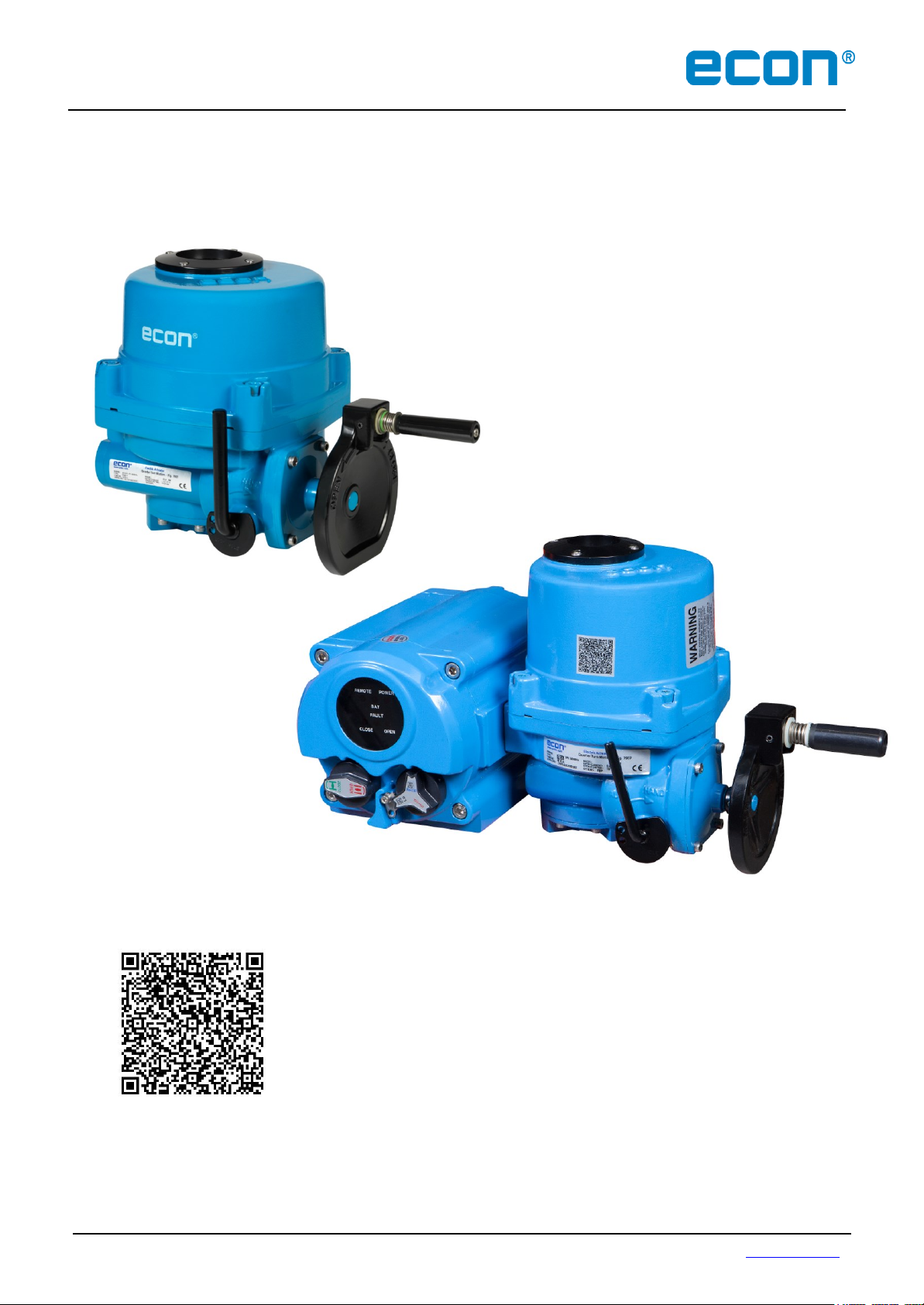
ECON ELECTRIC
Fig. 7907, type ELA80 - 3000
ACTUATOR
Compact quarter turn actuator
Mechanical position indicator
High output torque
Multi mounting base
Manual override
Installation and operation Manual for actuator type:
ELA80, 100, 150, 200, 300, 500, 600, 800, 1200, 2000, 2700 & 3000o, Republic
ECON actuator Fig 7907, type ELA80 – 3000 www.eriks.com
Rev.13 – January 7, 2019
:
Page 2

Installation & Operation Manual Proven Quality since 1892
Contents
1. INTRODUCTION 3
1.1 Purpose 3
1.2 Safety notices 3
2. PRODUCT IDENTIFICATION 4
2.1 Product
2.1.1 Marking 4
2.1.2 Applied Standards 5
2.1.3 Certification 5
2.2 Initial Inspection 5
2.3 Storage 5
3. GENERAL INFORMATION AND FEATURES 6
3.1 General Information 6
3.1.1
3.1.2
3.1.3 ELA-Series Options 7
3.1.4 Duty Cycle 7
3.1.5 Space Heater 7
3.1.6 Hand Wheel and Declutching 7
3.1.7 Lubrication 8
3.2 External Parts for Standard Models 8
3.2.1 ELA80-1200 8
3.2.2 ELA2000 - 3000 (Actuator + Gear Box) 8
3.3 Internal Parts for Standard
3.3.1 ELA80-3000 9
Standard Technical Data 6
ELA Actuator Versions and Additional Technical Data 6
4. INSTALLATION 10
4.1 Pre-installation 10
4.1.1 Use in General Service 10
4.1.2 Use in Potentially Explosive Atmosphere 10
4.2 Actuator Mounting 10
4.2.1
4.2.2
4.3
4.4
4.5
4.6
4.7 Setting Potentiometer (Optional
4.8
4.8.1 Standard Features 14
4.8.2
4.9 PCU-A Proportional Control Unit Alternating Current (Optional) 16
4.10
4.10.1 LED Signal Indication 18
4.10.2
4.11
4.12 Rechargeable Battery Pack – RBP (Optional) 25
4.12.1 General 25
4.12.2 Features 26
4.12.3 Specifications 26
4.12.4 PCB Layout 27
4.12.5 Operations 29
ECON actuator Fig. 7907, type ELA80 – 3000 www.eriks.com
Rev.13 - January 7, 2019 1
Actuator Mounting Base Details (ISO 5211) 11
Actuator Drive Bushing 11
Limit Switch Setting 12
Torque Switch Setting 13
Counter-Clockwise to Close Setting 13
Mechanical Travel Stop Adjustment 13
Current Position Transmitter – CPT (Optional) 14
Calibration of Zero and Span – CPT 15
PCU-D
Setting PCU Functions 18
AC/DC Multi-Board
Identification 4
Models 9
) 14
Proportional Control Unit Direct Current (Optional)
17
(Optional) 23
Page 3

Installation & Operation Manual Proven Quality since 1892
5. Fieldbus communication protocols (Optional) 30
5.1 ProfiBus Controler 30
5.1.1 Specification 30
5.2 ModBus Controler 30
5.2.1 Specification 31
6. OPERATION 32
6.1 Electrical Connections and Preliminary Test 32
7. MAINTENANCE 33
7.1 Maintenance 33
7.2 Tools 33
8. TROUBLE SHOOTING 34
9. INSTALLATION AND MAINTENANCE TIPS 35
APPENDIX I : Wiring Diagram 36
APPENDIX II : Grounding 55
ECON actuator Fig. 7907, type ELA80 – 3000 www.eriks.com
Rev.13 - January 7, 2019 2
Page 4
Installation & Operation Manual Proven Quality since 1892
1 INTRODUCTION
1.1 Purpose
The purpose of this manual is to introduce and explain the installation, operation and maintenance of
ELA-series electric actuators.
1.2 Safety Notices
This manual contains safety notices and precautions the user must take to reduce the risk of personal
injury and damage to the equipment. The user(s) must read these instructions before the installation,
operation or maintenance of the ELA-series electric actuators.
DANGER: Refers to personal safety and alerts the user for danger and/or injury.
Hazardous or unsafe practice may result in severe injury or death.
WARNING: Refers to personal safety. Alerts the user for potential danger.
Not following warning notices could result in personal injury or death.
CAUTION: Directs the user’s attention to general precautions that,
if not
followed, could result in personal injury and/or equipment
damage.
Note: Information in this manual is critical to the user’s understanding of the actuator’s installation
and operation.
ECON actuator Fig. 7907, type ELA80 – 3000 www.eriks.com
Rev.13 - January 7, 2019 3
Page 5
Installation & Operation Manual Proven Quality since 1892
2 PRODUCT IDENTIFICATION
2.1 Product Identification
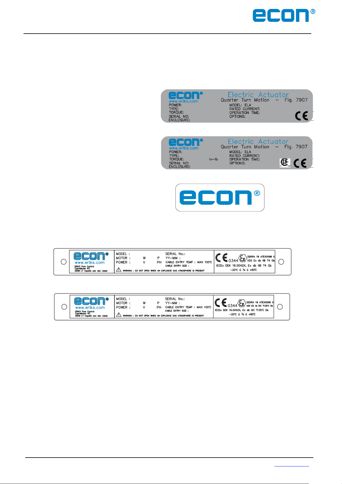
The actuator name plate is located on the opposite side of the conduit entry. The name plate
contains the following:
2.1.1 Marking
A) General
ECON logo (trade mark)
Electrical power supply
Model
Type
Rated current
Torque
Only applicable for North-American markets
Operation time (seconds)
Serial No.
Options
B) Additional Markings for Ex-version Actuators
Flame Proof versions
Dust Ignition Proof versions
ECON logo (trade mark)
CE ATEX and IECEx mark
Model
Motor specification
Ambient temperature
Production date
Serial number
Manufacturer’s address
Warning
ECON actuator Fig. 7907, type ELA80 – 3000 www.eriks.com
Rev.13 - January 7, 2019 4
Page 6

Installation & Operation Manual Proven Quality since 1892
2.1.2 Applied Standards
IEC60079–0:2011 (Ed.6 +ISO1), EN60079-0 :2012 +A11
IEC60079-1 :2014 (Ed.7), EN60079-1:2014
IEC60079-31 :2013 9ED.2), EN60079-31:2014
2.1.3 Certification
Series ELA80 ~ ELA3000
IECEx:
Ex db IIB T4 Gb, Ta -20°C to +60°C
Ex tb IIIC T135°C Db
ATEX
II 2 G Ex db IIB T4 Gb, Ta -20°C to +60°C
II 2 D Ex tb IIIC T135°C Db
Notes :
Sealing devices must be used and shall be fitted directly at the enclosure wall when using
conduit.
Cable glands shall be suitable for the environment and shall be certified as flameproof if used in
Zone 1 application.
Cable glands and conduit to be installed for minimum 6 full threads and the thread length must
be 8mm minimal.
The temperature of the cable entry is maximum 100℃. A heat resistance cable is recommended.
Ex db and/or Ex tb certified cable glands suitable for 100℃ must be used.
Minimal requirements concerning the material and the allowance of LCU fasteners:
o Fasteners with yield strength ≥ 210MPa (stainless steel)
o Bolts type: M5x0.8, M6x1, M8x1.25, M10x1.5, M12x1.75 (Tolerance Fit 6g).
Cable connection: Refers to the Appendix I - (Wiring Diagram)
For cable entries or conduit entries that are not used, user or installer shall close them with
certified blanking elements (stopping plugs) in order to maintain flameproof or dust ignition proof
properties of the enclosure.
Always ground the enclosure in accordance with local electric codes. The most effective
enclosure grounding method is a direct connection to earth ground with minimal impedance.
Methods for grounding the enclosure include:
o Internal ground connection: The internal ground is located in the terminal block #1. Refer
to the enclosed wiring diagram.
o External ground connection: The ground lug is located on the centre of cable entries. For
more information, refer to the Appendix II – (Grounding).
Stainless steel name plates for the flame proof and dust ignition proof versions shall be
permanently attached by rivets.
2.2 Initial Inspection
Upon on the receipt of the actuator, the user should inspect the condition of the product and
ensure that the product specification stated on the name plate matches with the order sheet.
Remove the packing wrap or wooden box carefully. Inspect the product for any physical
damage that may have occurred during shipment.
Check the product specification of the received product. If a wrong product has been
supplied, please immediately report this to the distributing company.
2.3 Storage
Actuators must be stored in a clean, cool and dry area. The unit should be stored with the cover
installed and the conduit openings sealed. Storage must be off the floor, covered with a sealed
dust protector.
ECON actuator Fig. 7907, type ELA80 – 3000 www.eriks.com
Rev.13 - January 7, 2019 5
Page 7

Enclosure Rated Weatherproof IP67, NEMA 4, 4X & 6
Enclosure High grade aluminium alloy, corrosion coated
Power Supply 115 / 230VAC ±5% 1Ph, 380 / 440 VAC 3Ph 50/60Hz
acc. To IEC 60034-1 24VAC and 24VDC
Duty Type See table in paragraph 3.1.2
Motor Squirrel caged induction motor
Limit Switches 2 x open/close SPDT, 250V AC 16A rating
Auxiliary Limit Switches 2 x open/close SPDT, 250V AC 16A rating (except for ELA80 and ELA100 Ex-versions)
Torque Switches Open/close SPDT, 250VAC 16A Rating (except for ELA80 and ELA100)
Stall Protection Built–in thermal protection
Travel Angle 90 degree +/- 10%
Indicator Continuous position indicator
Manual Override Declutchable manual override
Self-Locking By means of worm gear
Mechanical Travel Stops 2 x external adjustable mechanical travel stops
Space Heater See table in paragraph 3.1.5
Conduit Entries 2x M25 or 2x NPT 3/4 (for “Ex db" versions)
2x M20, 2x M25 or 2x NPT 3/4" with M30 adapter (for ”Ex tb” versions )
Lubrication Grease moly EP
Ambient Temperature
-20°C (-4°F) up to +80°C (176°F)
Ex-versions: -20°C (-4°F) up to +60°C (140°F) (CPT and PCU boards excluded)
External Coating D
ry Polyester powder coating
12VDC
24VDC
(24VAC)
2
115VAC
3
1 Phase
230VAC
3
1 Phase
230VAC
3
3 Phase
380VAC
3 Phase
440VAC
3 Phase
460VAC
3 Phase
Nm (in-lb)
s/90°
(50/60Hz)
A A
A
(50/60Hz)
A
(50/60Hz)
A
(50/60Hz)
A
(50/60Hz)
A
(50/60Hz)
A
(50/60Hz)
IEC 60034-1
S4
Number W kg (lbs)
ELA8 0 80 (708) 16/13 6,4 3,70 1 ,0/1,0 0,5/0,5 - 0,3/,04 0,6/0 ,4 -
70%
4
10
107
5
7,5 (16.5)
ELA1 00 1 00 (88 5) 20 /17 9,5 4 ,00 1,0/1,0 0,5/0,5 - 0,3/0,4 0,6/0,4 -
70%
4
10
107
5
7,5 (16.5)
ELA1 50 150 (1,328) 2 5/21 6,20 1,6/1,8 0,8/0,9 0,7/0,5 0,4/0,3 0,4/0,4 0,3/0,2 70% 11 216 16,5 (36.4)
ELA2 00 200 (1,770) 2 5/21 6,50 1,6/1,8 0,8/0,9 0,7/,05 0,4/0,3 0,4/0,4 0,3/0,2 70% 11 216 16,5 (36.4)
ELA3 00 300 (2,655) 3 1/26 3,00 1,4/1,7 0,7/0,9 0,5/0,4 0,4/0,3 0,5/0,3 0,3/0,3 70% 13,5 187 2 2 (48.5)
ELA5 00 500 (4,425) 3 1/26 - 4,3/3,6 1,4/1,3 0,9/0,8 0,6/0,5 0,7/0,5 0,5/0,4 70% 13,5 410 23 (50.7)
ELA6 00 600 (5,310) 3 1/26 - 4,3/3,6 1,4/1,3 0,9/0,8 0,6/0,5 0,7/0,5 0,5/0,4 70% 13,5 410 23 (50.7)
ELA8 00 800 (7,080) 3 7/31 - 3,6/5,0 1,9/2,8 1,5/1,1 0,9/0,7 1,1/0,7 0,8/0,6 70% 16,5 483 29 (63.9)
ELA1 200 1200 (10,620) 37 /31 - 3 ,6/5,0 1,9/2,8 1,5/1,1 0,9/0,7 1,1/0,7 0,8/0,6 70% 16,5 483 29 (63.9)
ELA2 000 2000 (17,701)
37/31
1
- 3,6/5,0 1,9/2,8 1,5/1,1 0,9/0,7 1,1/0,7 0,8/0,6 50% 49,5 483 75 (165.3)
ELA2 700 2700 (23,897)
56/47
1
- 3,6/5,0 1,9/2,8 1,5/1,1 0,9/0,7 1,1/0,7 0,8/0,6 50% 49,5 483 75 (165.3)
ELA3 000 3000 (26,552) 11 2/93 - 3,6/5,0 1,9/2,8 1,5/1,1 0,9/0,7 1,1/0,7 0,8/0,6 50% 49,5 483 75 (165.3)
Maximum
Power
Weight
Fig. 7907
type
Maximum
torque
Operating
time
Duty cycle
according to
Hand wheel
turns
Rated current
Installation & Operation Manual Proven Quality since 1892
3 GENERAL INFORMATION AND FEATURES
3.1 General Information
ECON ELA-series electric actuators are designed for the operation of industrial valves; e.g. butterfly
valves and ball valves.
The actuator has a torque output range from 80 Nm to 3,000 Nm (708 in-lbs to 26,552 in-lbs).
3.1.1 Standard Technical Data
3.1.2 ELA Actuator Versions and Additional Technical Data
Notes: 1. Operation time of 115V 1Ph actuators is 112/93 s/90°.
2. 24VAC actuators have 24VDC motors.
3. 115VAC and 230VAC ±5% according to IEC 60034-1
4. Duty ratings: ELA80 and ELA100 in 380 VAC/3Ph – S4-70% and 440 VAC/3Ph - S4-40%.
5. Maximum power at 3 Phase: S4-70%: 164 W and S4-40%: 348 W.
ECON actuator Fig. 7907, type ELA80 – 3000 www.eriks.com
Rev.13 - January 7, 2019 6
Page 8
EXD Flameproof enclosure
EXTB Dust ignition proof
WTA Watertight enclosure (IP68 (10m/72hr) Nema 6P
ATS Additional torque switches (SPDT x 2ea, 230VAC – 16A)
EXT Rotating extension - 120°, 180° or 270° (90° is standard)
ALS Additional limit switches (SPDT x 2ea, 230VAC – 16A)
PIU Potentiometer unit (0~1KΩ)
PCU Proportional control unit (input, output 0~10 VDC, 4~20mA DC)
CPT
Current position transmitter (output 4~20mA DC)
ADCM AC/DC Multi-board
SICU Semi-Integral Control Unit (LCU-B + IMS + phase protect indicator) (5W max.)
ICU Intelligent Digital Control Unit (LCU-C + IMS + auto phase discriminator) (5W max.)
PRB ProfiBus (5VDC, 0.1A max., in redundant configuration, multiplied by 2)
MOB ModBus (5VDC, 0.1A max., in redundant configuration, multiplied by 2)
Intermittent duty S4
The duty is a sequence of identical cycles which consist of starting time, operation time with constant
load and rest period. The rest period allows the machine to cool down so that thermal equilibrium is
not reached. The relative on-time at S4-25% or S4-50% is limited to 25% and 50% respectively.
Heating Element
Self-regulating
Voltage Range (ELA80~100) (based on the power supply)
115V 5W 4.5KΩJ
230V 5W 18KΩJ
24V DC 5W 200ΩJ
12V DC 5W 47ΩJ
Voltage Range (ELA150~3000) (based on the power supply)
115V 10W 2KΩJ
230V 10W 8KΩJ
24V DC 10W 100ΩJ
12V DC
10W 27ΩJ
Installation & Operation Manual Proven Quality since 1892
3.1.3 ELA-Series Options
3.1.4 Duty Cycle
Duty cycle rating according IEC60034-1 S4. See table in paragraph 3.1.2 for rating figures.
Exceeding the actuator’s rated duty cycle may cause thermal overload.
3.1.5 Space Heater
Condensation in the actuator is possible due to wide fluctuation of the ambient temperature. The
heater integrated in the control unit prevents this in general.
Ceramic housing with thermostat to prevent over heating with 60℃ set temperature.
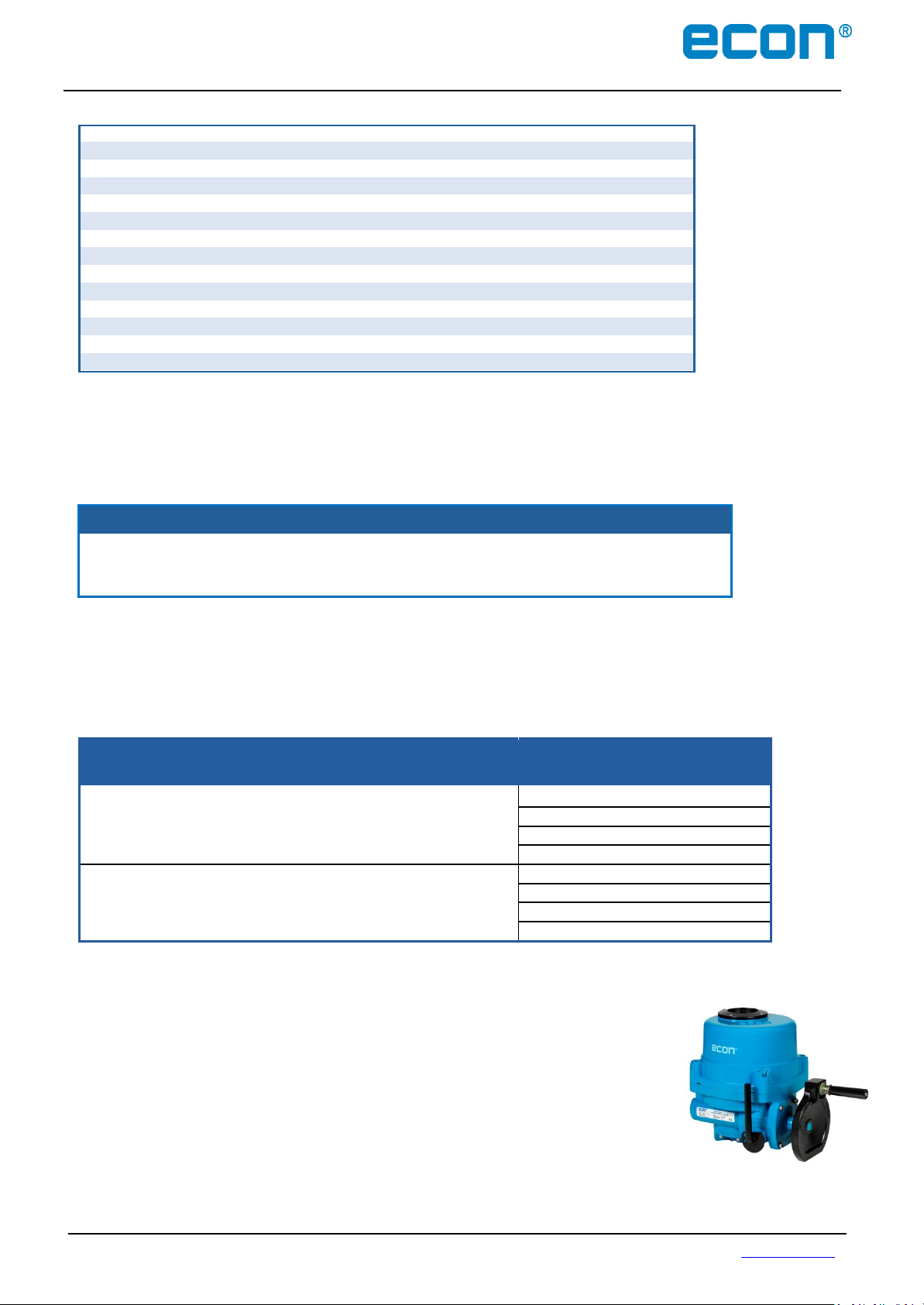
3.1.6 Hand Wheel and Declutching
ELA-series actuators are provided with a declutchable manual override
system.
In order to manually operate the actuator, pull the manual
override lever towards the hand-wheel until. It will remain in position.
Turn the hand-wheel until the valve reaches the required position.
Turn clockwise to close and counter-clockwise to open.
Note: The manual override lever returns automatically to auto-
position when the actuator is operated electrically.
ECON actuator Fig. 7907, type ELA80 – 3000 www.eriks.com
Rev.13 - January 7, 2019 7
Page 9
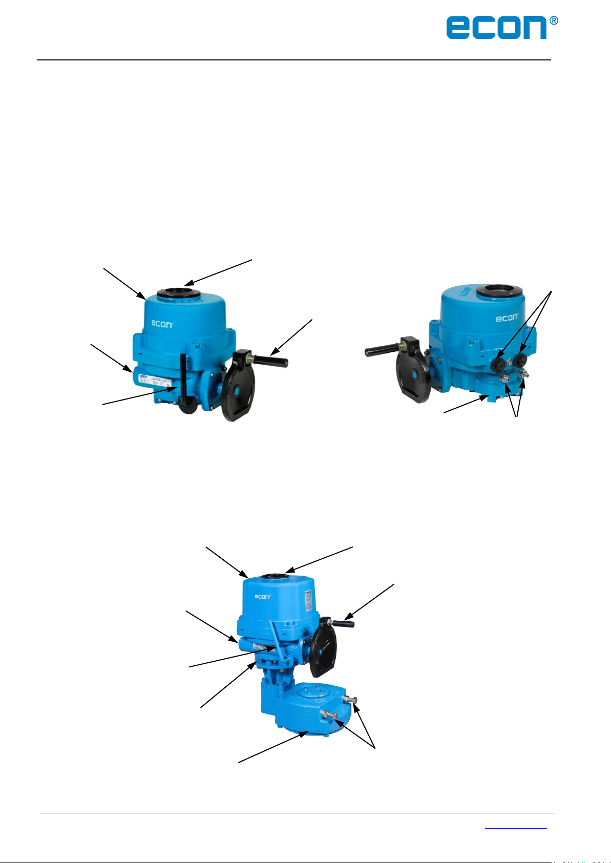
Body
Handwheel
Top cover
Lever
Window & Indicator
Mechanical
travel stops
Actuator base and
Driving bushing
Conduit
entries
Body
Gear box including
Driving bushing
Mechanical
travel stops
Handwheel
Top cover
Lever
Window & Indicator
Actuator base
Installation & Operation Manual Proven Quality since 1892
3.1.7 Lubrication
ELA-series are totally enclosed units with a permanent lubricated gear train (Moly EP Grease). Once
installed, lubricating the actuator should not be required. However, periodic preventative maintenance will
extend the operating life time of the actuator.
3.2 External Parts for Standard Models
3.2.1 ELA80 - 1200
3.2.2 ELA2000 - 3000 (Actuator + Gear Box)
ECON actuator Fig. 7907, type ELA80 – 3000 www.eriks.com
Rev.13 - January 7, 2019 8
Page 10
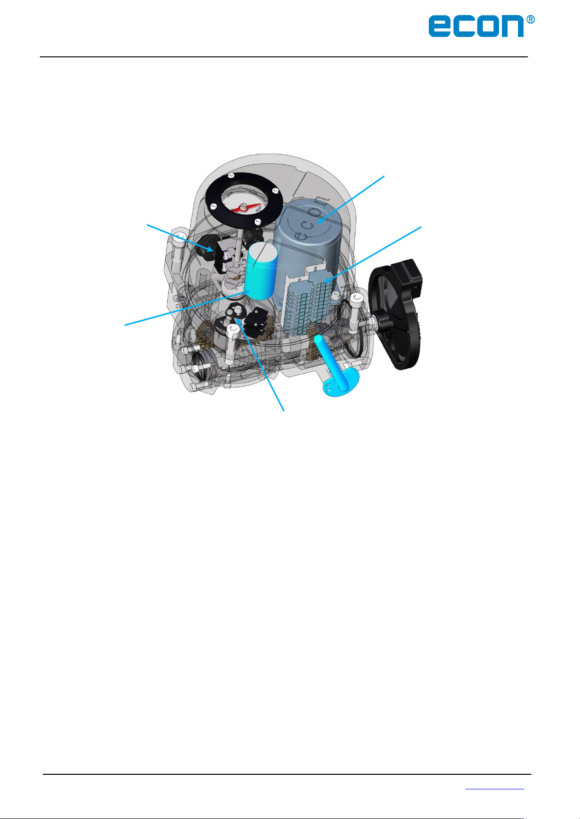
Motor
Terminal
block
Torque switch
assembly
Capacitor
Limit switch
assembly
Installation & Operation Manual Proven Quality since 1892
3.3 Internal Parts for Standard Models
3.3.1 ELA80 - 3000
Note: ELA80 and ELA100 do not have a torque switch provision!
ECON actuator Fig. 7907, type ELA80 – 3000 www.eriks.com
Rev.13 - January 7, 2019 9
Page 11
Installation & Operation Manual Proven Quality since 1892
4 INSTALLATION
4.1 Pre-installation
Please check if the electric power supply corresponds with your specification and the information on
the actuator type plate.
Make sure the power supply has been switched off before you start wiring the actuator.
4.1.1 Use in General Service
Verify the actuator’s nameplate to ensure that model number, torque output, operating speed, voltage
and enclosure type are correct before installation or use.
It is important to verify that the torque output of the actuator is appropriate for the torque requirements
of the valve and that the duty cycle of the actuator is appropriate for the intended application.
Make sure the power supply has been switched off before the actuator is being wired.
4.1.2 Use in Potentially Explosive Atmosphere
Model: ELA80 ~ ELA3000
Type of Enclosure : IECEx: Ex db IIB T4 Gb and Ex tb IIIC T135°C Db
ATEX: II 2 G Ex db IIB T4 Gb and II 2 D Ex tb IIIC T135°C Db
Ambient Temperature: -20°C (-4°F) up to +60°C (140°F)
WARNING:
Read this installation, operation and maintenance manual carefully
and completely before attempting to install, operate, or troubleshoot
the ELA
CAUTION:
Installation, commissioning, maintenance, repairs and modification work
may only be performed by qualified personnel with extensive knowledge on
how to work on explosion-proof electrical equipment.
actuator.
4.2 Actuator Mounting
Note: Prior to mounting, the part-turn actuator must be checked for any damage.
Damaged parts must be replaced by original spare parts
Mounting is most easily done with the valve shaft pointing vertically upwards. But mounting is also
possible in any other position.
The ELA-series electric actuators are supplied with a female double square drive output. The
ISO5211 bolt patterns are provided for actuator mounting. The actuator drive bush can be replaced or
removed for machining easily.
It is mandatory for the actuator to be firmly secured to a robust mounting bracket or t o be mou n t ed
directly to the valves’ ISO mounting pad. High tensile bolts or studs with spring locking washers must be
used.
The valve stem must be in line with the actuator output drive to avoid side loads to the shaft. To avoid
backlash play between the actuator, mounting bracket and valve is not allowed.
CAUTION:
Do not attempt to work on your ECON actuator without first shutting off the power supply
Do not attach ropes or hooks to the hand wheel for li fti ng purposes
ECON actuator Fig. 7907, type ELA80 – 3000 www.eriks.com
Rev.13 - January 7, 2019 10
Page 12
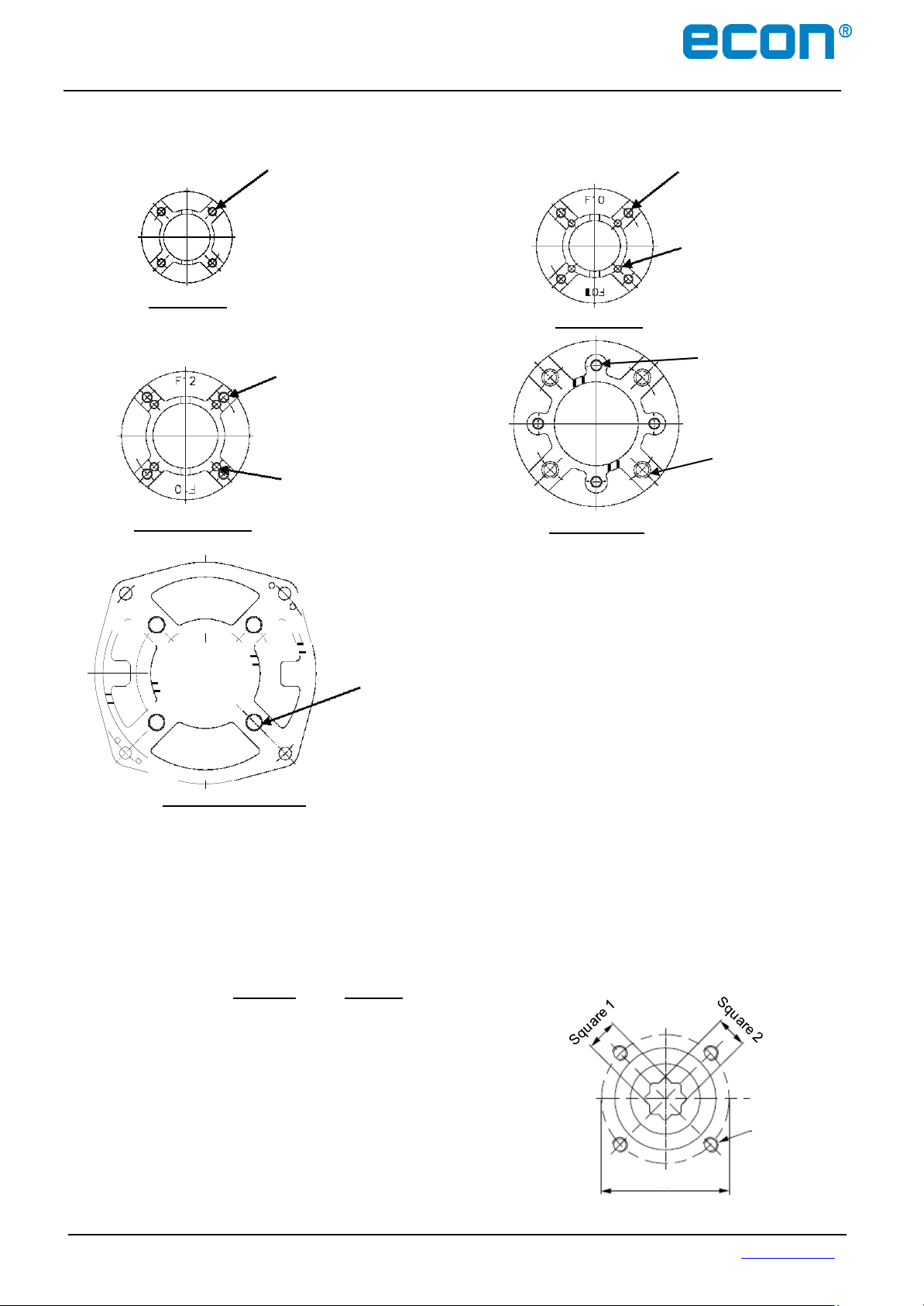
Threaded bolt
holes 4x
Pitch
Installation & Operation Manual Proven Quality since 1892
4.2.1 Actuator Mounting Base Details (ISO 5211)
4-M8TAP
D.P12
P.C.D Ø 70
ELA80/100
ELA300/500/600
(ISO 5211 F07)
4-M12TAP
D.P18
P.C.D Ø 125
(ISO 5211 F12)
4-M10TAP D.P15
P.C.D Ø 102
(ISO 5211 F10)
ELA150/200
ELA800/1200
4-M10TAP D.P15
P.C.D Ø 102
(ISO 5211 F10)
4-M8TAP
D.P12
P.C.D Ø 70
(ISO 5211 F07)
4-M12TAP D.P18
P.C.D Ø 125
(ISO 5211 F12)
4-M16TAP D.P24
P.C.D Ø 140
(ISO 5211 F14)
4-M20TAP D.P30
P.C.D Ø
(ISO
165
5211 F16
ELA2000/2700/3000
4.2.2 Actuator Drive Bushing
ELA actuators have a Double Square (star) driving bush, which can be replaced by another dimension to
fit the valve stem. This means that the actuators are suitable for valves with a parallel or diagonal stem
connection. Also drive bushings with a double-D shape or round shape with keyway are available as an
option. Hereunder the ELA-versions with standard connection
found:
Standard Optional
ELA80 DS 17mm DS 9-11-14-16mm
ELA100 DS 17mm DS 9-11-14-16mm
ELA150 DS 17mm DS 11-14-19-22mm
ELA200 DS 17mm DS 11-14-19-22mm
ELA300 DS 22mm DS 14-17-19-27mm
ELA500 DS 27mm DS 14-17-19-27mm
ELA600 DS 27mm DS 14-17-19-27mm
ELA800 DS 27mm DS 22mm
ELA1200 DS 27mm DS 22-30mm
ELA2000 DS 36mm DS 27-46-55mm
ELA2000 DS 36mm DS 27-46-55mm
ELA3000 DS 46mm DS 27-36-55mm
ECON actuator Fig. 7907, type ELA80 – 3000 www.eriks.com
Rev.13 - January 7, 2019 11
)
and possible double square options can be
Page 13
Installation & Operation Manual Proven Quality since 1892
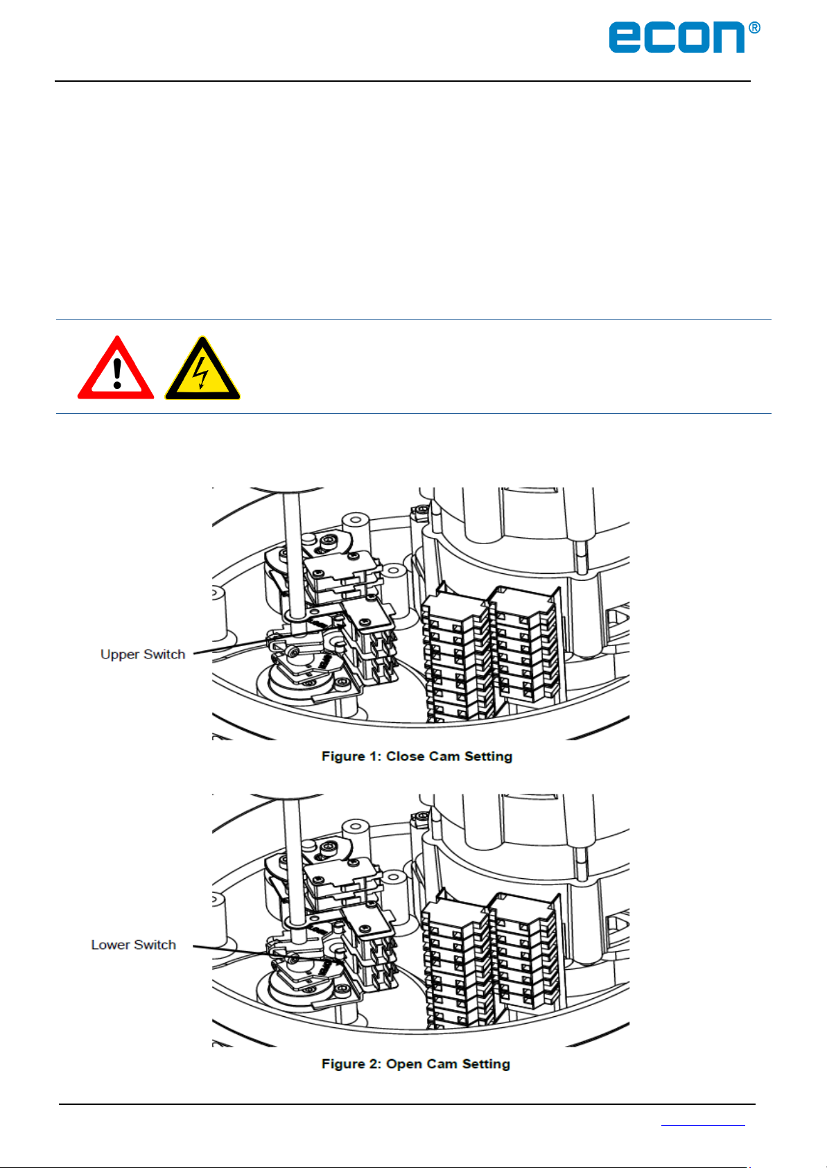
4.3 Limit Switch Setting
Rotate the hand wheel of the actuator manually to the fully closed position of the valve.
Use an Allen key, loosen the set screw of the CLOSE limit switch cam
Rotate the CLOSE cam CW until the limit switch ‘clicks’ (see Figure 1)
Tighten the set screw with the Allen key
Manually rotate the hand wheel of the actuator to the fully opened position of the valve
Use an Allen key to loosen the set screw of the OPEN limit switch cam
Rotate the OPEN cam CCW until the limit switch ‘clicks’ (see Figure 2)
Tighten the set screw with the Allen key.
DANGER:
HAZARDOUS VOLTAGE.
Make sure all incoming power is disconnected before setting the limit switches
ECON actuator Fig. 7907, type ELA80 – 3000 www.eriks.com
Rev.13 - January 7, 2019 12
Page 14
Installation & Operation Manual Proven Quality since 1892
4.4 Torque Switch Setting
The torque spring, which detects the variation of torque during the operation, is installed to prevent
damaging the valve and actuator under overload conditions. If an overload of the actuator occurs, the
torque switch will be activated and the actuator stops immediately.
The torque switches are set by manufacturer on the production site. If re-setting is necessary, please
contact the ECON actuator distributer before setting the torque switch.
CAUTION:
Do not reset t h e torque switch to a setting higher than the maximum setting
stated by the manufacturer.
4.5 Counter-Clockwise to Close Setting
Standard actuators are normally set to clockwise rotation to close. However, the rotation can be
reversed to counter-clockwise to close by simply reconfiguring the wiring as follows:
Reverse wiring on the main terminal block: 9 & 10 as well as 11 & 12.
Adjust the visual indicator to suit the counter-clockwise rotation.
If a PCU card is installed:
Reverse P1 (orange) and P3 (grey) on the PCU board.
Move the actuator manually to the half-open position and push the auto-reset button once.
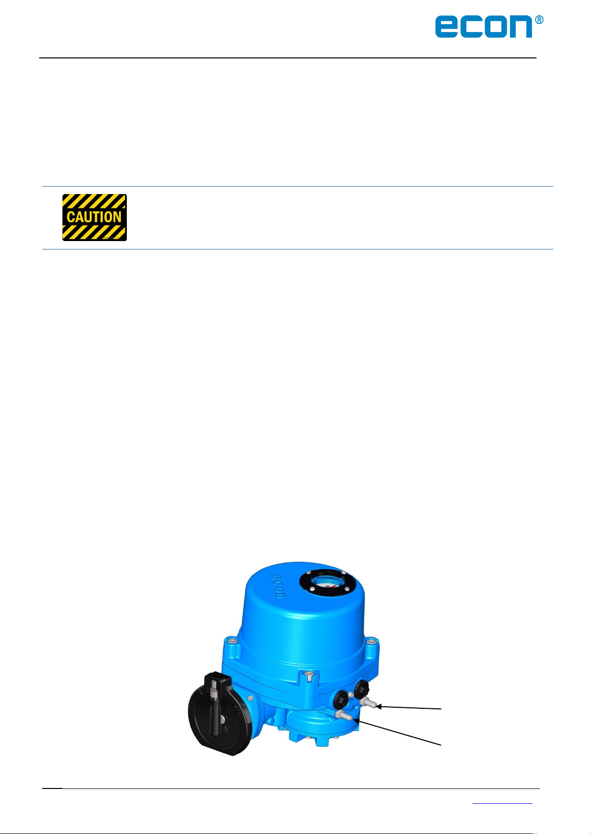
4.6 Mechanical Travel Stop Adjustment
Loosen both (open and close) travel stopper bolt nuts.
Operate the actuator manually by turning the hand wheel (the clutch lever must be
switched to “manual” first) to the closed position until the “close” open limit switch is being
activated.
Tighten the close travel stopper bolt until resistance is felt. (In this position the close travel
stopper bolt should not be able to travel any further).
Loosen back the close travel stopper bolt by only one turn and tighten the close travel stopper
bolt nut.
Repeat the same operation for setting of the open travel stopper bolt.
CLOSE TRAVEL
STOPPER BOLT
OPEN TRAVEL
STOPPER BOLT
ECON actuator Fig. 7907, type ELA80 – 3000 www.eriks.com
Rev.13 - January 7, 2019 13
Page 15
14 | P a g e
Model
CPT
Power
230(115) VAC ±5%, 50/60Hz 2VA Max
Output Signal
4~20mA DC
Output Impedance
750Ω Max
Resolution
Min 1/1000
Position Conversion Accuracy
±0.5 ~ ±1.5%
Ambient Temperature
-20°C (-4°F) up to +70C (158°F)
Ambient Humidity
90% RH Max (Non-condensing)
Dielectric Strength
1 s at (Rated VAC x 2 + 1000) x 1.2
(from Input to power ground)
Insulation Resistance
Above 500V DC 30MΩ
Vibration
10g, 0~34Hz
P1
P2
P3
Installation & Operation Manual Proven Quality since 1892
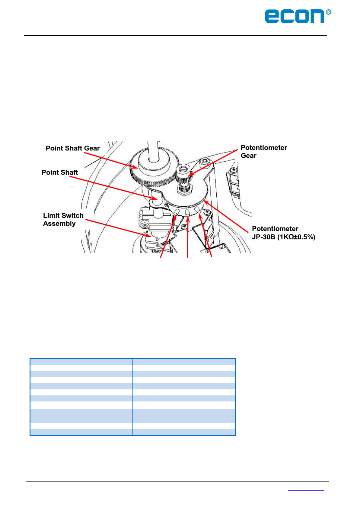
4.7 Setting Potentiometer (Optional)
The potentiometer has been calibrated at the factory. However, if re-calibration is required, proceed as
follows:
Manually rotate the hand wheel of the actuator to the fully closed position.
While measuring the resistance between P1 (black) and P2 (blue), gently rotate the
Potentiometer Gear until it reaches between 80 - 120 Ω (100 Ω preferred), by using a flat head
screw driver.
Engage the Potentiometer Gear into the Point Shaft Gear and use an Allen key to fasten the
locking bolt of the Potentiometer Gear.
4.8 Current Position Transmitter – CPT (Optional)
The potentiometer is used for the actuator signal feedback . It reads a resistance value w h i c h
corresponds with the
indicates the current position of the
si
gnal.
current position of the actuator and transfers i t to the CPT card.
actuator throughout the complete stroke by a 4 – 20mA output
The CPT
4.8.1 Standard Features
ECON actuator Fig. 7907, type ELA80 – 3000 www.eriks.com
Rev.13 - January 7, 2019 14
Page 16
Zero dial
Span dial
Installation & Operation Manual Proven Quality since 1892
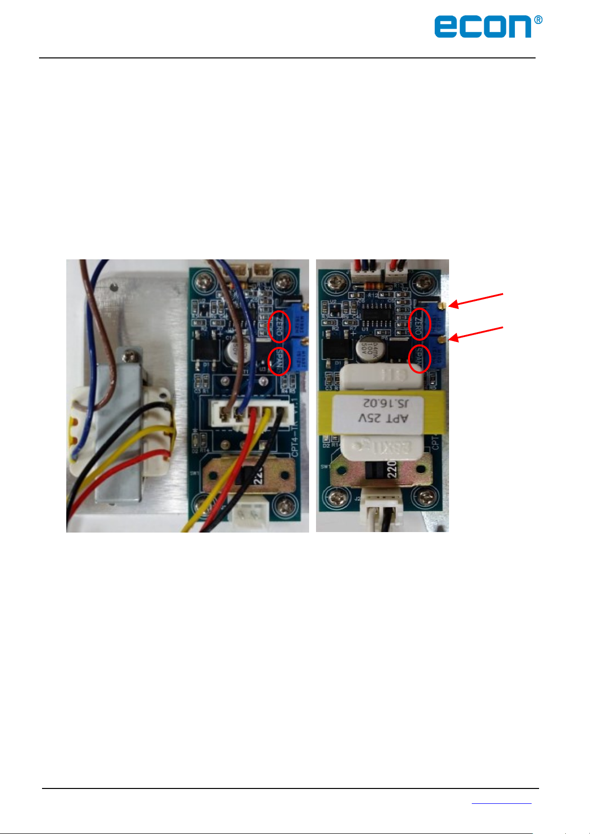
4.8.2 Calibration of Zero and Span - CPT
The settings of Zero and Span have been calibrated at the factory. However, if re-calibration is required,
proceed as follows:
Apply power (or use the manual override) to move the actuator to its fully closed position
(clockwise rotation).
When the actuator is in the fully closed position, adjust the ZERO close setting on the CPT board
until an output value of 4mA is achieved.
Apply power (or use the manual override) to move the actuator to its fully open position
(counter- clockwise rotation).
When the actuator is in the fully open position, adjust the SPAN open setting on the CPT board until
an output value of 20mA is achieved.
ECON actuator Fig. 7907, type ELA80 – 3000 www.eriks.com
Rev.13 - January 7, 2019 15
Page 17
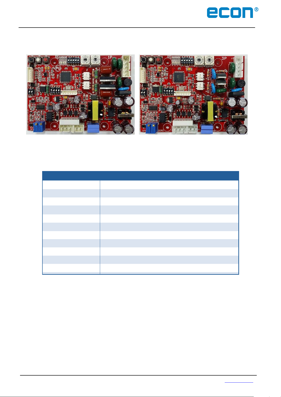
PCU-A Features
Model
PCU-A (1P and 3P)
Power
85 ~ 260 VAC Free Voltage ± 10%, 50/60Hz 4 VA Max
Input Signal
4~20mA DC, 1~5V DC, 2~10V DC, 0~5V DC, 0~10V DC
Input Impedance
250Ω
Output Signal
4~20mA DC, 1~5V DC, 2~10V DC, 0~5V DC, 0~10V DC
Output Impedance
250Ω Max
Output Contact
1 (Fault monitor)
Deadtime Adjustment
0.05~7.5 seconds
Deadband Adjustment
0.0625~1mA (0.0625mA + step no. x 0.0625mA, 15 steps total)
Ambient Temperature
-10°C (14°F) up to +70°C (158°F)
Ambient Humidity
90% RH Max (non-condensation)
PCU-A 1P
PCU-A 3P
Installation & Operation Manual Proven Quality since 1892
4.9 PCU-A – Proportional Control Unit Alternating Current (Optional)
PCU-A (1P and 3P) High performance Controller, using a 10 bit A/D converter and 8 bit
microprocessor technology.
The factory settings of the PCU card are normally set according to the customer requirements at the
time of order. However, we strongly recommend that input power, signal input selection and DIP switches
are to be verified prior to the actuator start up.
ECON actuator Fig. 7907, type ELA80 – 3000 www.eriks.com
Rev.13 - January 7, 2019 16
Page 18
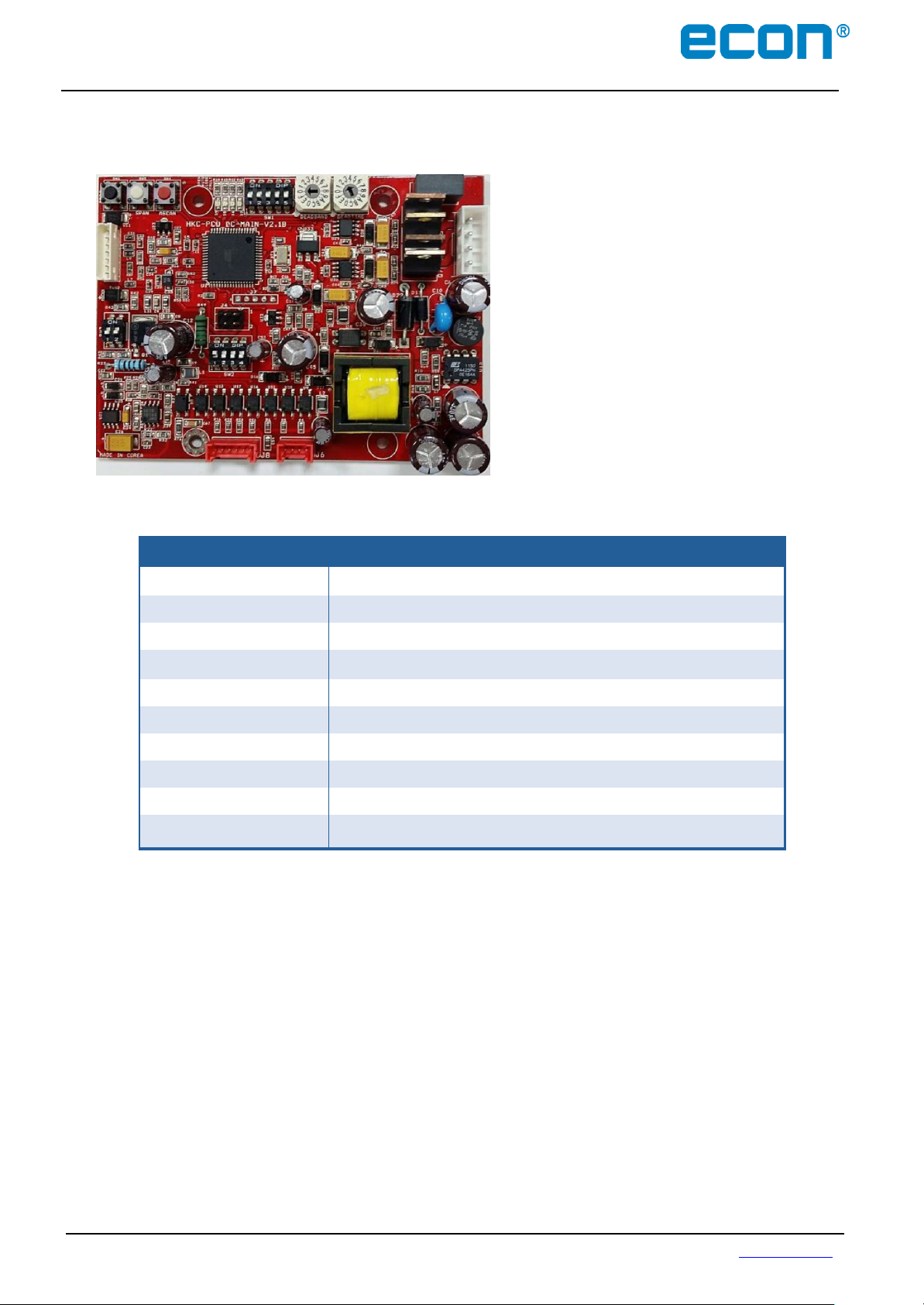
PCU-D Features
Model
PCU-D
Power
24V DC Voltage ± 15% (36V DC Max)
Input Signal
4~20mA DC, 1~5V DC, 2~10V DC, 0~5V DC, 0~10V DC
Input Impedance
250Ω
Output Signal
4~20mA DC, 1~5V DC, 2~10V DC, 0~5V DC, 0~10V DC
Output Impedance
250Ω Max
Deadtime Adjustment
0.05 ~ 7.5 seconds
Deadband Adjustment
0.0625~1mA (0.0625mA + step no. x 0.0625mA, 15 steps total)
Ambient Temperature
-25°C (-13°F) up to +80°C (176°F)
Ambient Humidity
90% RH Max (non-condensation)
Installation & Operation Manual Proven Quality since 1892
4.10 PCU-D – Proportional Control Unit Direct Current (Optional)
PCU-D High Performance Controller, using a
10 bit A/D converter and 8 bit microprocessor
technology
The factory settings of the PCU card are normally set according to the customer requirements at the
time of order. However, we strongly recommend that input power, signal input selection and DIP switches
are to be verified prior to the actuator start up.
ECON actuator Fig. 7907, type ELA80 – 3000 www.eriks.com
Rev.13 - January 7, 2019 17
Page 19

LED
State
Indication
Blue
On
Power on (auto)
Flickering
Auto calibrating
Green
On
Fully closed
Flickering
Closing
Red
On
Fully open
Flickering
Opening
Yellow
On
Manual mode
Flickering
Fault indication, either:
- no input signal
- wrong input wiring
- wrong PIU setting
Installation & Operation Manual Proven Quality since 1892
4.10.1 LED Signal Indication
4.10.2 Setting PCU Functions
A) Selecting Input
Note: If not specified, the factory setting of the input signal is 4 - 20mA.
ECON actuator Fig. 7907, type ELA80 – 3000 www.eriks.com
Rev.13 - January 7, 2019 18
Signal (SW7 on PCU-A or SW2 on PCU-D)
User can select different types of input signals by adjusting the DIP switches as follows:
DC
Input Signal
Switch
4 - 20mA DC
1 - 5V
2 - 10V DC
0 - 5V DC
0 - 10V DC
60 Hz (not applicable for PCU-D)
50 Hz (not applicable for PCU-D)
Page 20

Input signal switch No. 3
(PCU-A SW7 or
PCU-D SW2) “ON”
0 – 10V DC
Input signal switch No. 3
(PCU-A SW7 or
PCU-D SW2) “OFF”
2 – 10V DC
Input signal switch No. 3
(PCU-A SW7 or
PCU-D SW2) “ON”
0 – 5V DC
Input signal switch No. 3
(PCU-A SW7 or
PCU-D SW2) “OFF”
1 – 5V DC
Installation & Operation Manual Proven Quality since 1892
B) Selecting Output Signal (SW8 on PCU-A or SW3 on PCU-D)
User can select different types of output signals by adjusting the DIP switch as follows:
4 - 20mA DC
Output Signal
Switch
Note 1: If not specified, the factory setting of the output signal is 4 - 20mA.
Note 2: If the ELA150~3000, 115/230VAC actuators only will be operated by open and close
commands on terminal 11 and 12, the following procedure must be followed in order to select
the desired feedback signal:
• Select the output signal by adjusting the DIP switches as mentioned in this paragraph.
• Connect the power supply; Neutral on terminal 5 and Live on terminal 13.
• Make a link between terminal 13 and 14 and connect a multi-meter to terminal 17 and 18.
• Push “auto adjust” (red button on the circuit board) for 2 seconds.
• The actuator will now “auto adjust” itself.
• After the adjusting cycle has stopped, remove the link between 13 and 14.
• Now the actuator van be operated by giving the open and close commands on terminal 11
and 12. The feedback signal will be given on terminal 17 and 18.
• The feedback signal however still needs to be checked and if necessary adjusted. Therefor
measure the voltage or current on terminal 17 and 18, while opening and closing the
actuator. If necessary adjust the potentiometers “zero” and “span” on the bottom of the
circuit board until the output values are correct.
ECON actuator Fig. 7907, type ELA80 – 3000 www.eriks.com
Rev.13 - January 7, 2019 19
Page 21

Auto-Full Switch
(Switch 3) On (up)
Signal: 4.3~4mA
Fully Closed
Signal: 19.7~20mA
Fully Open
Auto-Full Switch
(Switch 3) Off (down)
Signal: 4mA
Fully Closed
Signal: 20mA
Fully Open
CH 2 Switch
CH 1 Switch
Auto-Full Switch
Fail Open Switch
Fail Close Switch
Fail Position
Setting Switch
Installation & Operation Manual Proven Quality since 1892
C) Fail Position Setting (SW3 on PCU-A or SW1 on PCU-D)
User can select the fail position of the actuator in case of control signal failure by adjusting
the DIP switches as follows:
Fail
Close
Fail
Open
Fail Last
Position
D) Special Signal Setting for Fully Open and Fully Closed
ECON actuator Fig. 7907, type ELA80 – 3000 www.eriks.com
Rev.13 - January 7, 2019 20
Page 22

Zero
Button
Span
Button
ASCAN
Button
Installation & Operation Manual Proven Quality since 1892
E) Auto Setting
This function is used for automatic setting of the PCU card to the predefined limits.
First make sure that the actuator has been mounted correctly on the valve. Secondly check the
input power and also the input and output signals. Press t h e ASCAN button once. Regardless
the position of the actuator, the actuator will now
ECON actuator Fig. 7907, type ELA80 – 3000 www.eriks.com
Rev.13 - January 7, 2019 21
perform the Auto Setting motion:
1) The blue LED starts flickering
2) The red LED starts flickering for 5 seconds
indicating that the actuator is moving to the
open position
3) Pause for 2 seconds
4) The green LED starts flickering, indicating
that the actuator is moving to the fully
closed position
5) Pause (the green LED on) for 3 seconds
6) The red LED starts flickering, indicating that
the actuator is moving to the fully open
position
7) Pause (the red LED on) for 3 seconds
8) Moving back to the command position
Note:
Since the actuator is already set at the factory, no further settings are required
unless the user has made adjustments to the Limit Switch or the Potentiometer
settings.
F) Manual Operation
This function allows the user to manually operate the
actuator.
To access this function, press the ZERO (black)
and SPAN (white) buttons simultaneously for 2
seconds and the yellow LED will be lit to indicate that
the actuator is in Manual Operation mode.
Pressing the ZERO button will move the actuator
to the close position and pressing the SPAN button
will move the actuator to the open position.
If no operation occurs within 5 seconds, the PCU
automatically terminates the Manual Operation mode
or alternatively press the ZERO and SPAN buttons
simultaneously for 2 seconds. In both cases, the
yellow LED will be lit off to indicate the termination of
the Manual Operation Mode.
Note: During the Manual Operation mode, the input signal is ignored.
Page 23

Set-points
Adjustable Range
Fully Closed
3 – 8mA DC
Fully Open
16 – 21mA DC
ZERO
Button
SPAN
Button
CH 1
Switch(4)
CH 2 Switch
(Switch 5) On (up)
4mA DC
Fully Open
20mA DC
Fully Closed
CH 2 Switch
(Switch5) Off (down)
4mA DC
Fully Closed
20mA DC
Fully Open
Dial
0 1 2 3 4 5 6
7
sec
0.05
0.2
0.4
0.6
0.8
2.5
3.0
3.5
Dial 8 9 A B C D E F
sec
4.0 4.5 5.0 5.5 6.0 6.5 7.0 7.5
CH 2
Switch(5)
ASCAN
Button
Deadtime
Dial
Installation & Operation Manual Proven Quality since 1892
G) Customizing Set-points (CH 1 Switch)
This function is used when the user wants to set
different set-points for fully open and fully closed
positions.
For example, if the user wants to assign 5mA as
the set-point for the fully closed position, first of all
switch- on (move up) the CH1 switch (switch 4).
Supply a 5mA signal and push the ZERO button
once. Hereafter, the actuator will acknowledge the
5mA signal as the set-point for the fully closed
position and transmits a 4mA feedback signal.
Similarly, for setting the set-point for the fully open
position, supply the desired signal (for example,
19mA) and push the SPAN button once. Switchoff (move down) the CH1 switch to complete the
setting. After this action, the actuator will operate
according this new setting.
H) Reversal Acting (CH 2 Switch)
This function allows the user to reverse the input
and output signals for the operation of the actuator.
For standard operation (CH 2 switch down), the
input signal of 4mA operates the actuator to the fully
closed position and the actuator transmits the output
signal of 4mA. However, if the CH 2 switch is on (
up) the input signal of 4mA operates the actuator to
the fully open position and still transmits a 4mA
output signal.
Manually move the actuator to the half-open
position and push the ASCAN button once to
execute the Auto Setting (see 4.10.2 E). Supply
signal and check the operation.
I) Deadtime
The actuator will only start to move if the change of
the input signal value is greater than the deadband
set value (see 4.10.2 J) and when the signal value
is maintained for the duration of the deadtime time.
This prevents malfunction of the actuator caused
by unwanted signals in the input signal such as
noise and interferences.
Turning the Delay Time Dial in clockwise
direction will increase the deadtime time (Range
0.05 to 7.5 seconds).
ECON actuator Fig. 7907, type ELA80 – 3000 www.eriks.com
Rev.13 - January 7, 2019 22
Page 24

Dial
0 1 2
3
mA DC
0.0625
0.125
0.1875
0.25
Dial
4 5 6
7
mA DC
0.3125
0.375
0.4375
0.5
Dial
8 9 A
B
mA DC
0.5625
0.625
0.6875
0.75
Dial
C D E
F
mA DC
0.8125
0.875
0.9375 1
Deadband
Dial
Installation & Operation Manual Proven Quality since 1892
J) Deadband Dial
The deadband adjusts the limits of the valve’s
deviation between an actual position and a target
position. The dead band is set to 0.12mA DC
max.
Deadband indicates the extent of the reaction on
the input signal.
Low deadband setting may cause the actuator
to hunt or to unnecessarily respond to a
fluctuating input signal. If so, the deadband must
be increased.
Turning the Deadband Dial in clockwise direction
will increase the resolution (Range 0.0625mA to
1mA).
4.11 AC/DC Multi-Board (Optional)
A) Power Open-Close Terminal block
1 Power 24V AC/DC (DC + signal block)
2 None
3 None
4 Open signal
5 Close signal
6 Power 24V AC/DC (DC – signal block)
B) Power Input Switch
ECON actuator Fig. 7907, type ELA80 – 3000 www.eriks.com
Rev.13 - January 7, 2019 23
Page 25

Installation & Operation Manual Proven Quality since 1892
For AC Mode, #1 switch turn “ON”
and #2 switch turn “OFF”
DC Mode, #1 switch turn “OFF” and
#2 switch turn “ON”
Note: Don’t operate both switches #1 and #2 at the same time. It may damage the board
C) Motor Terminal Block
Red motor wire must be connected to block # 1
Black motor wire must be connected to block # 2
ECON actuator Fig. 7907, type ELA80 – 3000 www.eriks.com
Rev.13 - January 7, 2019 24
Page 26

Installation & Operation Manual Proven Quality since 1892
4.12 Rechargeable Battery Pack – RBP (Optional)
Warning
Please check if the electric power supply corresponds with your specification and the information on the actuator type
plate.
Make sure the power supply has been switched off before you start wiring the actuator.
The life time of the battery is 2 years, subject to operating time and environment. It should be replaced after 2 years in
order to guarantee a good working product.
After electric power has been supplied on terminal strip number 2 and 3, please connect number 1 and 4 with a jumper
as shown on the wiring diagram. Please make sure that number 1 and 4 are connected. This connection must be
maintained as long as the electric power supply is connected.
If the actuator will not be operated for a long period of time, please disconnect terminal strip number 1 and 4 in order to
extend battery life.
The battery must be discharged and charged regularly every 2 to 3 months.
4.12.1 General
The ECON actuator with Rechargeable Battery Pack (RBP) can be operated in Local or
Remote mode by using two selector switches on the local control unit. During power failure the actuator
can be operated 5 times by the battery pack. The actuator shows high reliability due to its self-checking c
apability. The local control unit shows the position of the valve,
status of the actuator and errors if occurring.
ECON actuator Fig. 7907, type ELA80 – 3000 www.eriks.com
Rev.13 - January 7, 2019 25
Page 27

Items
Condition
Electric Power Supply
1 Phase – AC 115 V / 230 V 50/60Hz
Internal Voltage
Control Voltage : DC 24 V / 30 V
Voltage for Space Heater : AC 115/230 V
Power Consumption
40 VA
Temperature / Humidity
-20 ~ 70°C / 60 % RX, MAX.
Actuator functions by DIP
switch settings
DIP Switch setting
DIP switch 1
OFF
INCHING
ON
HOLD
DIP switch 2
OFF
Fault Contact Normal Open
ON
Fault Contact Normal Close
Power Fail action
DIP switch 3
DIP switch 4
FUNCTION
OFF
OFF
STOP
OFF
ON
CLOSE
ON
OFF
OPEN
ON
ON
NO POWER FAIL ACTION
Installation & Operation Manual Proven Quality since 1892
4.12.2 Features
The actuator unit can be operated in Local or Remote mode, also during power failure.
The DIP switch settings and functions can be found in the table in paragraph 4.
NORMAL MODE (on AC POWER): Battery LED blinks 1.5 seconds ON and 0.5 seconds OFF
BATTERY MODE (on BATTERY POWER) : Battery LED blinks 0.25 seconds ON and 1.75
seconds OFF
4.12.3 Specification
ECON actuator Fig. 7907, type ELA80 – 3000 www.eriks.com
Rev.13 - January 7, 2019 26
Page 28

5
7
6
4
8
9
10
12
3 2 1
11
Installation & Operation Manual Proven Quality since 1892
4.12.4 PCB Layout
1. DC Power Connector
2. Battery Connector
3. Battery Switch Connector
4. Limits / Torque Signal Connector
5. Remote Control Signal
6. Status Contactor
7. PCU Signal
8. Motor Connector
9. AC Power Monitor (option)
10. DIP Switches
11. Power check
12. Battery active switch
Note:
If the actuator does not work on battery power, despite of a fully charged battery and a jumper
has been placed on terminal strip connection number 1 and number 4, please press the battery
active switch (12).
ECON actuator Fig. 7907, type ELA80 – 3000 www.eriks.com
Rev.13 - January 7, 2019 27
Page 29

LED status
1. BLUE
BLINK
REMOTE MODULATING
MODE
ON
REMOTE MANUAL MODE
2.WHITE
OFF
AC POWER OFF
ON
AC POWER ON
3.GREEN
BLINK
CLOSING
ON
FULLY CLOSED
4.RED
BLINK
OPENING
ON
FULLY OPEN
5. AMBER
OFF
NO ERROR/FAULT
ON
ERROR message
6.BATTERY
(BLINKING)
GREEN
HIGH CHARGING
BLUE
MIDDLE CHARGING
RED
LOW CHARGING
RED STEADY ON
NO BATTERY
1
2
6
3
4
5
Installation & Operation Manual Proven Quality since 1892
ECON actuator Fig. 7907, type ELA80 – 3000 www.eriks.com
Rev.13 - January 7, 2019 28
Page 30

Local Operation
1. Put the selector switch into Local Mode.
2. Use the open/close switch to operate the actuator.
3. In Local Mode the LED indicators will show the below status:
RED LED – ON : Fully Open
GREEN LED – ON : Fully Close
RED or Green LED – Blinking : Opening or closing
Remote (Manual mode) Operation
1. Put the selector switch into Remote Mode.
2. Manual Mode is functional if terminal strip number 5 and 9 are NOT wired.
3. In Manual Mode the LED indicators will show the below status:
BLUE LED – Steady ON : Manual mode
For wiring diagrams see drawings D7907-3 RBP and D7907-4 RBP on page 41-49
Remote (Modulating mode) Operation
1. Put the selector switch into Remote Mode.
2. Modulating Mode is functional if terminal strip number 5 and 9 are wired.
3. In Modulating Mode the LED indicators will show the below status:
BLUE LED – Blinking: Modulating mode
4. For actuator operation please refer to the paragraph 4.10 (PCU settings).
For wiring diagram see drawing D7907-4 RBP+PCU on page 50
Battery Mode Operation
1. If the power supply has been switches off, the actuator will be powered by the battery.
2. LOCAL MODE: Operate the Open/Close switch in order to put the actuator in the open or closed
position.
3. REMOTE MODE: During power failure, the actuator will follow the power failure settings (DIP
switch settings – see paragraph 4.12.4)
4. NO FAIL ACTION : The actuator will operate the same way as if there was not power failure.
Installation & Operation Manual Proven Quality since 1892
4.12.5 Operations
ECON actuator Fig. 7907, type ELA80 – 3000 www.eriks.com
Rev.13 - January 7, 2019 29
Page 31

Item
Description
Input power
87V ~ 270V ac ±10% , 50/60Hz ±2% 4VA max.
Input power must match motor ratings
Communication
ProfiBus communication (RS-485 base)
Max. range
1000m @ 9.6 ~ 187.5 k Baud
Bit rate
Up to 12mega
Wiring terminals
SMW250-3P * 4 ( ProfiBus signal )
YW396-5P (Main power & Motor)
SMW250-8P (CTS, OTS, CLS, OLS contact input)
SMW250-6P (Firmware update connector)
SMW250-4P (Debug connector)
Visual indicators
Power white, blue LED
Fault yellow LED
Motor open red LED
Motor close green LED
Control configuration
PC software
Output contact
Triac 250V ac, 16A max. (Inductive load)
Ambient temperature
-10℃ ~ +60℃
Ambient humidity
90% RH max. (non-condensing)
ProfiBus PCB
Termination PCB
ModBus PCB
Installation & Operation Manual Proven Quality since 1892
5 FIELDBUS COMMUNICATION PROTOCOL
5.1 ProfiBus Contoller
The ProfiBus Controller is providing multiple communication
functions by using a 8 bit microprocessor and ProfiBus controller.
Providing the operator with actuator status information in order to
confirm if the ProfiBus device and actuator is working
correctly
The maximum transmission speed is 12Mbit/s.
Easily can be switched between PCU-version and ON-
OFF-version.
Providing System Redundancy by using dual ports and
high reliability.
LED lamps indicate the actuator status.
5.1.1 Specification
5.2 ModBus Controller
This clause explains the ModBus-RTU Slave
Module (MBRSM). Positioned at level 7 of the
OSI model, ModBus is an application layer
messaging protocol that provides client/server
communication between devices connected on
different types of buses or networks.
As a ModBus Serial Line protocol, ModBus-RTU
(Remote Terminal Unit) is a Master-Slave
protocol which takes place at level 2 (Data Link
layer) of the OSI model. The master initiates the
communication by transmitting the Function Code
(a ‘request’) to the address of a slave and after
receiving and processing the Function Code, the slave returns a message (a ‘response’).
The slaves shall not communicate with each other without the request of the master. Since the
ECON actuator Fig. 7907, type ELA80 – 3000 www.eriks.com
Rev.13 - January 7, 2019 30
Page 32

Installation & Operation Manual Proven Quality since 1892
MBRSM is based on the 2 wire (half-duplex) RS-485 communication, the network length limit or
the number of station should follow the standards of the RS-485 communication. To extend the
network, such as adding another segment, repeaters can be used. To ensure stability of the
network system, the network redundancy can be configured to slave redundancy.
ModBus manages the access of data simply and flexibly. ModBus supports two data types: A
Boolean value and an unsigned 16-bit integer. Generally, it is common for field devices to have
certain values defined as inputs while other values are outputs, such as current temperature or
valve position.
5.2.1 Specification
Communication Protocol: ModBus-RTU according to IEC 61158 and IEC 61784
Topology: Line topology with termination
Number of nodes: 32 nodes in each segment without repeater, with repeaters expandable to 247
Number of repeaters: Max. 9 with signal refreshing
Cable length: Max. 1.2 Km with Repeater 10 Km
Transfer Mode: RS-485
Transmission Medium: Twisted, shielded 2-Wire cable according to IEC 61158
Bus Access: Polling between master and slaves (query response)
Supported Baud Rates: 1200, 2400, 4800, 9600, 19200, 38400, 57600, 115200
Supported Parity Bit: Odd, Even, None
Supported Stop Bit: 1, 2
For more detail information, please refer to separate ModBus operation manual.
ECON actuator Fig. 7907, type ELA80 – 3000 www.eriks.com
Rev.13 - January 7, 2019 31
Page 33

Installation & Operation Manual Proven Quality since 1892
6 OPERATION
6.1 Electrical Connections and Preliminary Test
WARNING:
If working in potentially explosive areas, observe the European
Standards EN 60079-14 “Electrical Installation in Hazardous Areas” and
EN 60079-17 “Inspection and Maintenance of Electrical Installations in
Hazardous Areas”. Work on the electrical system or equipment must
only be carried out by a skilled electrician himself or by specially
instructed personnel under the control and supervision of such an
electrician and in accordance with the applicable electrical engineering
rules.
For cable gland or conduit entries that are not used, user or installer
shall close those entries by certified blanking elements in order to
maintain the enclosure protection. Extra attention is required for
selecting the correct “Ex db IIC” or “Ex tb IIC” blanking elements.
For cleaning a dust ignition proof closure, a damp cloth shall be used.
An explosion proof enclosure must be treated with care. Seals and
sealing surfaces may not be damaged in any way. Do not jam during
assembly.
Dust ignition proof enclosures may not be charged with an electrostatic
load. It therefor shall be installed in such a way, that the risk from
electrostatic discharge and propagation brush discharge, caused by
rapid flow of dust, is avoided.
For testing purposes, loosen the bolts of the actuator cover and remove the cover.
Make sure that the power supply voltage is in accordance with the information on the
nameplate of the actuator.
Cables shall be passed through the cable glands: M25 or NPT ¾” for “Ex db” versions. M25, M20
and NPT ¾” with M30 adapter shall only be applied for “Ex tb” versions.
Connect wires according to the enclosed wiring diagram (See Appendix I)
Manually move the valve to the half-open position. Then electrically operate the actuator to
the fully open position and check if the motor rotates in the correct direction. According to the
applicable standards, the actuator must be closing in counter-clockwise direction.
Test the actuator and check whether the limit switches work correctly
After testing, check if all cable glands are correctly tightened. Applicable cable glands must be
selected to meet the application’s condition. It is recommended to use at least IP67 cable glands.
Put the cover back on the actuator and tighten the bolts.
DANGER:
HAZARDOUS VOLTAGE. Electrical power must not be connected
until all wiring and limit switch adjustments have been
completed. Once the power is supplied to the actuator,
precautions must be taken if the cover is not mounted.
Note: For more information, refer to Appendix II
ECON actuator Fig. 7907, type ELA80 – 3000 www.eriks.com
Rev.13 - January 7, 2019 32
Page 34

Installation & Operation Manual Proven Quality since 1892
7 MAINTENANCE
7.1 Maintenance
WARNING:
Turn off all power before performing maintenance on the actuator.
POTENTIALLY HIGH PRESSURE VESSEL. Before removing or
disassembling your actuator, ensure that the valve or other actuated
device is isolated and not under pressure.
Under normal conditions, maintenance should be carried out at six month intervals. But when the
conditions are more severe, more frequent inspections may be advisable.
Ensure that the actuator is properly aligned with the valve (stem) or other actuated device
Ensure that all wires are insulated and connected properly
Ensure that all screws are present and tightened
Ensure that all internal electrical devices are clean (dry and free of dust)
Ensure that conduit connections are properly installed and are dry
Check the internal devices for any condensation
Check the power supply of the internal heater
Check the enclosure O-ring seals and verify that the O-rings are not pinched
Check the declutch mechanism
Visually inspect the open/close cycle
For Ex-actuators the cover seal O-ring needs to be inspected and replaced if damaged.
Inspect the identification labels for wear and replace it if necessary
Damaged or broken parts may only be replaced by genuine parts
WARNING:
Flameproof Enclosure! Before opening, ensure the absence of any
gas and voltage
Treat cover with care. Seals and sealing surfaces may not be damaged
or dirty in any. Do not jam the cover during mounting.
7.2 Tools
Metric Allen Key (Hex Wrench) × 1
Screw Driver × 1
Metric Spanner × 1
Wrench 200mm × 1
Wrench 300mm × 1
Wire Stripper Long Nose × 1
Multi-meter (AC, DC, Resistance) × 1
PCU Board Option: DC Signal Generator (4 – 20mA DC) × 1
In case a PCU-A or –D board has been mounted: DC signal generator (4-20mA DC) x 1
In case a PCU and CPT board has been mounted: mA Meter (0~25mA) x 1
ECON actuator Fig. 7907, type ELA80 – 3000 www.eriks.com
Rev.13 - January 7, 2019 33
Page 35

Installation & Operation Manual Proven Quality since 1892
8 TROUBLE SHOOTING
The following instructions are listed in the order of the most common difficulties encountered
during the installation and start-up.
► The actuator does not respond
Visually inspect the actuator and check if no damage has occurred during shipping and handling of
the actuator.
Verify the line voltage supplied to the actuator; it must match with the rating on the actuator’s
nameplate
Compare and check the internal wiring with the supplied wiring diagram of the actuator
Check the limit switch cams
► The actuator is supplied with power but does not operate
Verify the line voltage supplied to the actuator; it must match with the rating on the actuator’s
nameplate.
Make sure that the actuator output torque is greater than the required valve torque
Check the limit switch cams
Check if the torque switches have not been tripped
Check the mechanical travel stop adjustment
Check if the rotating direction matches (According to the applicable standards, valves and actuators
must open in counter-clockwise direction)
Check the internal wiring
Check for any corrosion and condensation. Electrical or mechanical devices may have been
affected
Verify if coupler/bracket is correctly installed and may not block the actuator rotation
► Actuator runs erratically
Check the ambient temperature
Verify that the duty cycle has not been exceeded
Check the position of the manual override lever
► Optional Equipment(s)
1) Potentiometer
Check the resistance value
Check the potentiometer gear for jamming
Check the ZERO and SPAN calibration and confirm input/output signal
Check the board for any damage
2) Current Position Transmitter
Verify the input signal
Check the configuration of the dip switches
Check the board for any damage
ECON actuator Fig. 7907, type ELA80 – 3000 www.eriks.com
Rev.13 - January 7, 2019 34
Page 36

Installation & Operation Manual Proven Quality since 1892
9 INSTALLATION AND MAINTENANCE TIPS
WARNING:
If working in potentially explosive areas, be sure to comply with the
standard EN 60079-14 “Electrical Installation in Hazardous Areas”
Work on an actuator with an open cover and which is under voltage,
may only be performed if there is no explosion danger for the duration
of the work.
In case of an explosion proof enclosure, the actuator may only be
opened in the absence of flammable gas, dust and voltage.
During operation, installation and maintenance, treat cover with care.
Seals and sealing surfaces may not be pinched, damaged or dirty in
any way. Damaged seals (O-rings) must be replaced.
Dust ignition proof enclosures may not be charged with an electrostatic
load. It therefor shall be installed in such a way, that the risk from
electrostatic discharge and propagation brush discharge, caused by
For any installation and maintenance work, the followings should be noted:
Check the actuator visually. Ensure that no external damage or changes are visible. The
electrical cables must not be damaged and wired correctly.
Cable entries, cable glands, plugs, etc. have to be checked whether they are correctly
tightened and sealed.
Check if the Ex-connections are correctly fastened.
Check for possible discoloration of the terminal strip and wires as this may indicate an
increased temperature.
Check the flame path seals of the explosion proof enclosures for any dirt and corrosion. Since
the dimensions of all Ex seals are strictly defined and inspected, no mechanical work shall be
performed on them.
All cables and motor protection elements have to be checked.
If any defects are detected during maintenance that may affect the safety, repair measures have
to be taken immediately.
Any kind of coating for sealing surfaces is not permitted.
When replacing parts, seals, etc., only original spare ones must be used.
ECON actuator Fig. 7907, type ELA80 – 3000 www.eriks.com
Rev.13 - January 7, 2019 35
rapid flow of dust, is avoided.
CAUTION:
Regular inspection and maintenance should be performed by
qualified and trained personnel
If working in potentially explosive areas, be sure to comply with the
standard EN 60079-14 “Electrical Installations in Hazardous Areas”.
Working on the actuator that is in open position and under voltage
must only be performed if it is assured that there is no danger of
explosion for the duration of the work.
Pay attention to national regulations
Page 37

Installation & Operation Manual Proven Quality since 1892
APPENDIX 1 : Wiring Diagrams
DANGER: HAZARDOUS VOLTAGE. Electrical power must not be connected
until all wiring and limit switch adjustments have been completed.
ECON actuator Fig. 7907, type ELA80 – 3000 www.eriks.com
Rev.13 - January 7, 2019 36
Page 38

Installation & Operation Manual Proven Quality since 1892
DANGER: HAZARDOUS VOLTAGE. Electrical power must not be connected
until all wiring and limit switch adjustments have been completed.
ECON actuator Fig. 7907, type ELA80 – 3000 www.eriks.com
Rev.13 - January 7, 2019 37
Page 39

Installation & Operation Manual Proven Quality since 1892
DANGER: HAZARDOUS VOLTAGE. Electrical power must not be connected
until all wiring and limit switch adjustments have been completed.
ECON actuator Fig. 7907, type ELA80 – 3000 www.eriks.com
Rev.13 - January 7, 2019 38
Page 40

Installation & Operation Manual Proven Quality since 1892
DANGER: HAZARDOUS VOLTAGE. Electrical power must not be connected
until all wiring and limit switch adjustments have been completed.
ECON actuator Fig. 7907, type ELA80 – 3000 www.eriks.com
Rev.13 - January 7, 2019 39
Page 41

Installation & Operation Manual Proven Quality since 1892
DANGER: HAZARDOUS VOLTAGE. Electrical power must not be connected
until all wiring and limit switch adjustments have been completed.
ECON actuator Fig. 7907, type ELA80 – 3000 www.eriks.com
Rev.13 - January 7, 2019 40
Page 42

Installation & Operation Manual Proven Quality since 1892
DANGER: HAZARDOUS VOLTAGE. Electrical power must not be connected
until all wiring and limit switch adjustments have been completed.
ECON actuator Fig. 7907, type ELA80 – 3000 www.eriks.com
Rev.13 - January 7, 2019 41
Page 43

Installation & Operation Manual Proven Quality since 1892
DANGER: HAZARDOUS VOLTAGE. Electrical power must not be connected
until all wiring and limit switch adjustments have been completed.
ECON actuator Fig. 7907, type ELA80 – 3000 www.eriks.com
Rev.13 - January 7, 2019 42
Page 44

Installation & Operation Manual Proven Quality since 1892
DANGER: HAZARDOUS VOLTAGE. Electrical power must not be connected
until all wiring and limit switch adjustments have been completed.
ECON actuator Fig. 7907, type ELA80 – 3000 www.eriks.com
Rev.13 - January 7, 2019 43
Page 45

Installation & Operation Manual Proven Quality since 1892
DANGER: HAZARDOUS VOLTAGE. Electrical power must not be connected
until all wiring and limit switch adjustments have been completed.
ECON actuator Fig. 7907, type ELA80 – 3000 www.eriks.com
Rev.13 - January 7, 2019 44
Page 46

Installation & Operation Manual Proven Quality since 1892
DANGER: HAZARDOUS VOLTAGE. Electrical power must not be connected
until all wiring and limit switch adjustments have been completed.
ECON actuator Fig. 7907, type ELA80 – 3000 www.eriks.com
Rev.13 - January 7, 2019 45
Page 47

Installation & Operation Manual Proven Quality since 1892
DANGER: HAZARDOUS VOLTAGE. Electrical power must not be connected
until all wiring and limit switch adjustments have been completed.
ECON actuator Fig. 7907, type ELA80 – 3000 www.eriks.com
Rev.13 - January 7, 2019 46
Page 48

Installation & Operation Manual Proven Quality since 1892
DANGER: HAZARDOUS VOLTAGE. Electrical power must not be connected
until all wiring and limit switch adjustments have been completed.
ECON actuator Fig. 7907, type ELA80 – 3000 www.eriks.com
Rev.13 - January 7, 2019 47
Page 49

Installation & Operation Manual Proven Quality since 1892
DANGER: HAZARDOUS VOLTAGE. Electrical power must not be connected
until all wiring and limit switch adjustments have been completed.
ECON actuator Fig. 7907, type ELA80 – 3000 www.eriks.com
Rev.13 - January 7, 2019 48
Page 50

Installation & Operation Manual Proven Quality since 1892
DANGER: HAZARDOUS VOLTAGE. Electrical power must not be connected
until all wiring and limit switch adjustments have been completed.
ECON actuator Fig. 7907, type ELA80 – 3000 www.eriks.com
Rev.13 - January 7, 2019 49
Page 51

Installation & Operation Manual Proven Quality since 1892
DANGER: HAZARDOUS VOLTAGE. Electrical power must not be connected
until all wiring and limit switch adjustments have been completed.
ECON actuator Fig. 7907, type ELA80 – 3000 www.eriks.com
Rev.13 - January 7, 2019 50
Page 52

Installation & Operation Manual Proven Quality since 1892
DANGER: HAZARDOUS VOLTAGE. Electrical power must not be connected
until all wiring and limit switch adjustments have been completed.
ECON actuator Fig. 7907, type ELA80 – 3000 www.eriks.com
Rev.13 - January 7, 2019 51
Page 53

Installation & Operation Manual Proven Quality since 1892
DANGER: HAZARDOUS VOLTAGE. Electrical power must not be connected
until all wiring and limit switch adjustments have been completed.
ECON actuator Fig. 7907, type ELA80 – 3000 www.eriks.com
Rev.13 - January 7, 2019 52
Page 54

Installation & Operation Manual Proven Quality since 1892
DANGER: HAZARDOUS VOLTAGE. Electrical power must not be connected
until all wiring and limit switch adjustments have been completed.
ECON actuator Fig. 7907, type ELA80 – 3000 www.eriks.com
Rev.13 - January 7, 2019 53
Page 55

Installation & Operation Manual Proven Quality since 1892
DANGER: HAZARDOUS VOLTAGE. Electrical power must not be connected
until all wiring and limit switch adjustments have been completed.
ECON actuator Fig. 7907, type ELA80 – 3000 www.eriks.com
Rev.13 - January 7, 2019 54
Page 56

Installation & Operation Manual Proven Quality since 1892
APPENDIX II :
ELA80 - 100 Grounding
Internal Ground External Ground
Grounding
Terminal Block #1 should be used for internal ground
ELA150 - 3000 Grounding
Internal Ground External Ground
Terminal Block #1 should be used for internal ground
DANGER:
Flameproof Enclosure! Before opening, ensure that there
is no explosive gas or voltage
ECON actuator Fig. 7907, type ELA80 – 3000 www.eriks.com
Rev.13 - January 7, 2019 55
Page 57

56 | P a g e
Installation & Operation Manual Proven Quality since 1892
If you have questions about this product,
Please contact the nearest ECON distributor.
You can find them on www.eriks.com
ERIKS Flow Control
Cypresbaan 63,
2908 LT Capelle aan den IJssel,
The Netherlands
Phone: +31 (0)10 284 1100
ECON actuator Fig. 7907, type ELA80 – 3000 www.eriks.com
REV.13 - January 7, 2019 54
 Loading...