

Page 1

Installation & Operation Manual Proven Quality since 1892
ECON Limit Switch Box Fig. 79652 www.eriks.com
Rev.0 1
ECON Limit Switch Box
Fig. 79652
Scan for manual
Installation & Operation Manual for Limit Switch Box: Fig. 79652
Page 2

Installation & Operation Manual Proven Quality since 1892
ECON Limit Switch Box Fig. 79652 www.eriks.com
Rev.0 2
Contents Page
1. INTRODUCTION 3
2. SWITCH BOX SPECIFICATION 3
3. SWITCH TYPE SELECTION 3
4. SWITCH BOX MARKING 3
5. STANDARD FEATURES 4
6. INITIAL INSPECTION 5
7. STORAGE 5
8. INSTALLATION 5
8.1 Mounting of the Limit Switch Box 5
8.2 Setting of switch/sensor cams 6
8.3 Cam types 6
8.4 Wiring of the Limit Switch Box 6
8.4.1 Mechanical switch - 2 SPDT (Standard) 7
8.4.2 Proximity switch - P&F NBB2-V3-Z4L 7
8.4.3 Proximity switch - P&F NBB2-V3-E2 8
8.4.4 Mechanical switch - 2 SPDT with CPT, Current Position Transmitter (Optional) 8
8.5 Setting of the Current Position Transmitter unit – CPT (Optional) 9
8.5.1 Calibration of the potentiometer 9
8.5.2 Calibration of the zero span 9
9. MAINTENANCE 10
10. TROUBLE SHOOTING 10
11. TOOLS 11
12. GENERAL INSTALLATION AND MAINTENANCE TIPS 11
Page 3

Installation & Operation Manual Proven Quality since 1892
ECON Limit Switch Box Fig. 79652 www.eriks.com
Rev.0 3
1 INTRODUCTION
The ECON Fig. 79652 limit switch box is designed to provide accurate and reliable valve position information of
actuated valves and hand operated valves.
The Fig. 79652 limit switch box consists of an aluminium body a polycarbonate visual position indicator, quick-set
cam assemblies, terminal strip, switch assemblies and an easy mounting bracket. Quick-set cams enable rapid
manual switch adjustments. Tools are not required.
2 SWITCH BOX SPECIFICATION
Model: Fig. 79652
Enclosure rating: Weather-proof IP67, NEMA 4, 4X and 6. (optional IP68, NEMA 6P)
Enclosure: High grade anodized Aluminium alloy
Ambient temperature range: -20°C (-4°F) up to +80°C (176°F)
Conduit entries: 2x M20x1,5 or 2x NPT1/2” (optional PG13,5)
Travel angle: 90° +/-10%
Visual position indicator: Open: Yellow; Close: Red. Language: English (Open / Closed)
Switch types: See chapter 3 for standard switch types
Terminal strip 8 point; 0,08-2,5mm
2
(optional : 9 to 14 points)
External coating: Dry powder polyester
Potentiometer (optional): 1kΩ (optional : 0~5kΩ , 0~10kΩ)
Current output signal unit (optional): 4~20mA, 20~4mA
3 SWITCH TYPE SELECTION
ECON code
Position feedback devices
Switch/Sensor specification
EC79652000AMS
Micro Switch, 2-SPDT
Starion, SZM-V16-5FA-61
EC79652004AMS
Micro Switch, 4-SPDT
Starion, SZM-V16-5FA-61
EC7965200APS22
Proximity Sensor, 2-wire (minimum off-state current)
Pepperl & Fuchs, NBB2-V3-Z4L
EC79652000APS3
Proximity Sensor, 3-wire
Pepperl & Fuchs, NBB2-V3-E2
EC79652000CPT
4-20mA position transmitter (CPT) and
Micro Switch, 2-SPDT
Starion, SZM-V16-5FA-61
Other switches or sensors can be fitted upon request. Please contact your local distributer.
4 SWITCH BOX MARKING
ECON-logo
Figure number (Fig.)
Switch type specification
Switch certification information
QR-code for I.O.M (Installation and Operation Manual)
Enclosure rating
EC79652000AMS & EC79652004AMS EC79652000CPT
EC7965200APS22 EC79652000APS3
Page 4
Installation & Operation Manual Proven Quality since 1892
ECON Limit Switch Box Fig. 79652 www.eriks.com
Rev.0 4
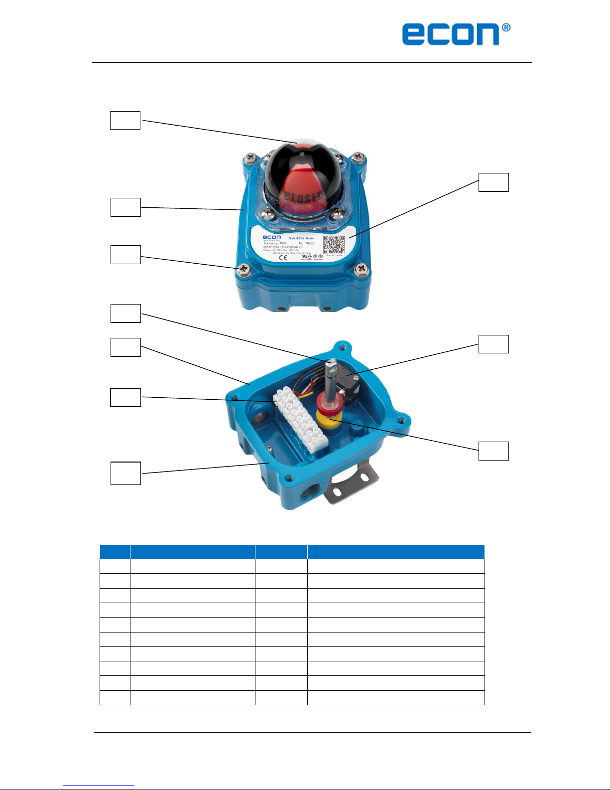
5 STANDARD FEATURES
No.
Part Name
Q’ty
Description
1
Window / Indicator
1
Polycarbonate / ABS
2
Cover Captive Cover Bolt
4
Stainless steel
3
Cover
1
Aluminium Die casting
4
Name Plate 1 Sticker
5
Shaft 1 Stainless steel
6
Body
1
Aluminium Die casting
7
Terminal Strip
1
8 positions
8
Cams 2 PC
9
Switch
2
See switch type specification (chapter 3)
10
Grounding Lug
1
Stainless steel
4 2 3 1 5 6 7
8
9
10
Page 5

Installation & Operation Manual Proven Quality since 1892
ECON Limit Switch Box Fig. 79652 www.eriks.com
Rev.0 5
6 INITIAL INSPECTION
Upon on the receipt of the switch box, the user should inspect the condition of the product and ensure that the
product specification stated on the name plate matches with the order sheet.
Remove the packing wrap or cardboard box carefully. Inspect the product for any physical damage that may
have occurred during shipment.
Check the product specification of the received product. If a wrong product has been supplied, please
immediately report this to the distributing company.
7 STORAGE
Limit switch boxes must be stored in a clean, cool and dry area. The unit should be stored with the cover installed
and the conduit openings sealed. Storage must be off the floor, covered with a sealed dust protector.
8 INSTALLATION
8.1 Mounting of the limit switch box
CAUTION: PREVENT INJURIES
Before installing the limit switch box on the actuator, air supply and
power supply of the pilot valve must be shut off.
ECON limit switch boxes are supplied with a mounting bracket according to the VDI/VDE 3845 (NAMUR) standard.
This standard bracket is selected for actuators with a VDI/VDE connection 30x80 mm and an actuator shaft height of
30mm. Brackets for other VDI/VDE dimensions are available upon request and are mentioned in the table below.
Available bracket sizes
ECON code
30x80mm, Height: 30 mm (standard)
EC7965X0BR80X30
30x80mm, Height: 20 mm
EC7965X0BR80X20
30x130mm, Height: 30 mm
EC7965X0BR130X30
Put the actuator in the fully open or closed position.
Mount the bracket on the switch box.
Put the switch box with bracket on the actuator and do not
tighten the bolts yet (4 pieces).
Check the actuator shaft and switch box shaft alignment
Check if the position of the open and closed switches/sensors
and also the visual position indicator corresponds with the valve position.
Tighten the bolts in order to secure the bracket to the actuator (4 pieces).
Check again if the position of the open and closed switches/sensors
and also the visual position indicator corresponds with the valve position.
Page 6

Installation & Operation Manual Proven Quality since 1892
ECON Limit Switch Box Fig. 79652 www.eriks.com
Rev.0 6
8.2 Setting of switch/sensor cams
The colour of the cams corresponds with the visual position indicator. Cams can be easily set without using any tools.
ECON cams have a spline connection and can be set by lifting or pushing down the cams over the shaft . The cams
are spring loaded and therefore self-locking.
Note : Cams are pre-set by the factory for most standard applications. This setting however must always be
checked before commissioning.
Loosen the switch box cover bolts.
Remove the cover carefully.
Setting of the open-cam setting:
- Put the actuator in the fully open position.
- Lift the yellow (lower) cam and rotate it until the switch is activated.
- Release the cam and it will lock itself to the shaft.
Close cam setting
- Put the actuator in the fully closed position.
- Push the red (upper) cam down and rotate it until the switch is activated.
- Release the cam and it will lock itself to the shaft.
8.3 Cam types
8.4 Wiring of the limit switch box
DANGER:
HAZARDOUS VOLTAGE. Electrical power must not be connected until all
wiring and limit switch adjustments have been completed. Once the
power is supplied to the actuator, precautions must be taken if the cover
is not mounted.
Cams for mechanical switches
Cams with metal insert for
proximity sensors
Splined cam
Page 7

Installation & Operation Manual Proven Quality since 1892
ECON Limit Switch Box Fig. 79652 www.eriks.com
Rev.0 7
ECON limit switch boxes have prewired switches. All user connections must be made on the numbered terminal strip.
A wiring diagram, located inside the cover, indicates which terminal numbers correspond with switch contacts. Follow
the wiring diagram in order to make a correct connection to your system.
A solenoid valve may also be wired through the ECON limit switch box. Two auxiliary terminals (EXT) are included as
a standard.
ECON limit switch boxes have two cable entries and are being supplied with a blanking cap/plug. A cable gland must
be selected by the user or installer and must meet the applicable enclosure rating
8.4.1 Mechanical switch – 2 SPDT (Standard)
8.4.2 Proximity switch - P&F NBB2-V3-Z4L
Page 8

Installation & Operation Manual Proven Quality since 1892
ECON Limit Switch Box Fig. 79652 www.eriks.com
Rev.0 8
8.4.3 Proximity switch - P&F NBB2-V3-E2
8.4.4 Mechanical switch - 2 SPDT with CPT, Current Position Transmitter (Optional)
Note:
The limit switch box must be grounded at all times.
At least a 2 sq. mm wire is recommended for grounding.
Page 9

Installation & Operation Manual Proven Quality since 1892
ECON Limit Switch Box Fig. 79652 www.eriks.com
Rev.0 9
8.5 Setting of the Current Position Transmitter unit – CPT (Optional)
A potentiometer reads the current position of the actuator (valve) and transmits a resistance value to the
position transmitter PCB. The transmitter indicates the actuator (valve) position throughout the complete stroke and
converts resistance value it into a 4 to 20mA output signal.
Technical features
Power supply range : 12.5 to 37VDC (25V typical)
Current signal output: 4 to 20mA
Max. load resistance: Max. resistance (Ohm) = (Supply voltage – 12.5) / 0.02
Potentiometer: 0 to 500Ω / 10kΩ
Operation temperature: -20 to 60°C (-4°F to 140°F)
Dimension: 40 x 60 x 15mm
DC power supply
8.5.1 Calibration of the potentiometer
Operate the actuator into the closed position.
Connect an Ohm-meter to the P1 and P3 resistor. The value shall be approximately 1kΩ.
Loosen the potentiometer gear wheel from the shaft and connect the Ohm-meter to P1 and P3
and rotate the gear wheel gently until a value between 80 to 120Ω is achieved (100Ω preferred!).
While maintaining the value, tighten and lock the gear wheel to shaft.
8.5.2 Calibration of the zero span
The zero span setting has been calibrated by manufacturer. However, if re-calibration is required, please
follow the hereunder mentioned instruction:
Operate the actuator to the middle position and thereafter to the fully closed position.
As soon as the actuator reaches the fully closed position, adjust the “zero” rotary switch on the
PCB until a value of 20mA is achieved.
Page 10

Installation & Operation Manual Proven Quality since 1892
ECON Limit Switch Box Fig. 79652 www.eriks.com
Rev.0 10
9 MAINTENANCE
The ECON Fig. 79652 limit switch box is designed to provide accurate and reliable valve position signalling and
indicating of most automated valves.
WARNING:
Inspection and maintenance work must be performed by qualified and trained
personnel
When working in potentially explosive areas, the standard EN 60079-14
“Electrical Installations in Hazardous Areas” must be observed.
Work on an open limit switch box, which is under voltage, may only be
performed if there is no explosion risk.
Observe local and national regulations and legislation.
Flame proof enclosures may only be opened if there is no explosion risk.
CAUTION:
Shut-off all incoming power or air supply on the valve actuator before starting
maintenance work on the limit switch box.
Be sure that the working area is clean before disassembling the limit
switch box. Clean all parts and seals before re-assembling.
Use only genuine spare parts, which can be purchased from your local ECON
distributer.
Maintenance should be performed every six month or after every 100,000 operation cycles. In severe operation
conditions inspections must be performed more frequently. During maintenance the following parts of the limit switch
box must be inspected:
Check the alignment of the valve, actuator and limit switch box.
Check the wiring insulation and the terminal strip connections.
Check the adjustment of the cams.
Check the cams on wear and replace them if necessary.
Check if al screws are present and tightened.
Check if the cable connections are installed properly and not leaking.
Check internal devices for condensation.
Check the enclosure for damages, especially on the sealing surfaces.
Check the enclosure O-ring seals and also check if the O-ring is in the correct position.
Visually inspect the limit switch box during operation.
Inspect the type plate of the limit switch box and replace it if necessary.
10 TROUBLESHOOTING
The following instructions are offered for the most common difficulties that could be encountered during installation
and start-up.
Signal errors to main control room.
Check if the wiring of the limit switches/sensors is in accordance to the wiring diagram.
Check if the cams or switches/sensors are damaged or broken.
Check the connections on the terminal strip.
Re-set the limit switch box
Check the potentiometer gear for jamming (if present)
Check the zero and span calibration if a CPT has been installed.
Check the PCB for damages if a CPT has been installed.
Page 11

Installation & Operation Manual Proven Quality since 1892
ECON Limit Switch Box Fig. 79652 www.eriks.com
Rev.0 11
11 TOOLS
For installation or maintenance the below tools may be necessary:
1 Set of metric Allen keys
1 Set of screw drivers
1 Set of metric spanners
1 Wire stripper with long nose
1 Needle nose plier
1 Multi-meter (AC, DC, Resistance)
12 GENERAL INSTALLATION AND MAINTENANCE TIPS
For any installation and maintenance work, the following should be observed:
Check the limit switch box visually. Ensure that no outside damages or changes are visible. The electric
connecting cables must be without damage and wired correctly.
Cable entries, cable glands, plugs etc. have to be checked for tightness.
Check whether Ex-connections are fastened correctly.
Take care of possible discolorations of the terminals and wires.
Check the flame path gaps of flameproof enclosures for dirt and corrosion. Since the
dimensions of all Ex gaps are strictly defined and inspected, no mechanical work shall be performed on
them.
Ensure that all enclosure seals are handled carefully and are being checked for damages. All cables and
cable entry seals have to be checked.
If defects are found during maintenance, repair measures must be taken immediately.
Sealing surfaces must not be coated.
Parts may only be exchanged by genuine parts.
 Loading...