

Page 1
Installation & Operation Manual
Proven Quality since 1892
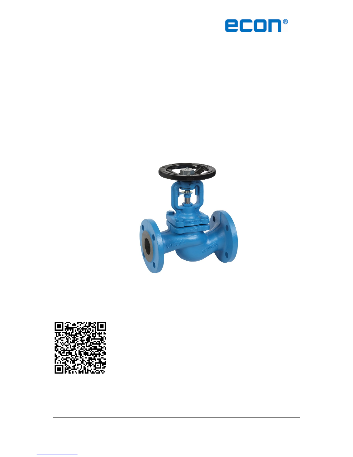
ECON bellows seal valves Fig. 430, 431, 432, 433, 434 www.eriks.com
Rev.3
ECON BELLOWS SEAL VALVES
Fig. 430, 431, 432, 433 & 434
Scan for manual
Operating and Instruction Manual for Bellows seal valves:
Fig. 431, 431, 432, 433 & 434
Page 2

Installation & Operation Manual
Proven Quality since 1892
ECON bellows seal valves Fig. 430, 431, 432, 433, 434 www.eriks.com
Rev.3
Content
1. ERIKS operating companies
2. Product description
3. Requirements for maintenance staff
4. Transport and storage
5. Function
6. Application
7. Installation
8. Maintenance
9. Service and repair
10. Features
11. Options
12. Troubleshooting
13. Removal
1. ERIKS operating companies
ECON bellows seal valves are being delivered by several ERIKS operating companies on a
worldwide basis. In this manual these will be referred to as ‘ERIKS’, the individual terms of
delivery of the ERIKS operating company having executed the order are applicable.
2. Product description
The ECON bellows seal valves are designed according EN-13789 and information in our latest
catalogue or see our website www.eriks.com and should be used in accordance with the
applicable pressure-temperature rating as stated on this website. ECON bellows seal valves are
provided with casted markings according to EN 19. The marking makes the identification of the
valve easier and contains:
- size (DN)
- pressure rating class
- body material marking
- arrow, indicating the medium flow direction
heat numbers (when required)
- CE marking when applicable
- tag plate
- ECON logo
3. Requirements for maintenance staff
The staff assigned to assembly, operating and maintenance tasks should be qualified to carry out
such jobs and in any circumstance, ensure personal safety
4. Transport and storage
Transport and storage should always be carried out with the discs complete closed and the valve
should be protected against external forces, influence and destruction of the painting layer as well.
The purpose of the painting layer is to protect the valve against rust, during transport and storage.
The valves should be stored in an unpolluted space and should also be protected against all
atmospheric circumstances. There should be taken care of the temperature and humidity in the
room, in order to prevent condensate formation.
It is not allowed to fit lifting devices to connection holes, handwheel or stem.
5. Function
ECON bellows seal valves are designed to stop the flow of a medium. The bellow gives a fully
sealed stem connection with zero leakages acc. to emission requirements of TÜV. The valve is
closed by turning the hand wheel clockwise; don’t use tools to increase the torque on the hand
wheel.
Page 3

Installation & Operation Manual
Proven Quality since 1892
ECON bellows seal valves Fig. 430, 431, 432, 433, 434 www.eriks.com
Rev.3
6. Application
ECON bellows seal valves are widely used for steam, cold and hot water, thermal oil, air, gasses,
etc. for shut off or connection of pipeline. The valves are designed for standard operating
conditions. For the use of extreme conditions e.g. aggressive or abrasive media, it is
recommended to mention this at the ordering stage, to verify whether the valve is suitable. The
installation designer is responsible for the globe valve selection, suitable for the working
conditions. The valves are unsuitable, without written permission of an ERIKS company, to apply
for hazardous media as referred into Regulation (EC) No 1272/2008.
7. Installation
During the assembly of the standard ECON bellows seal valves, the following rules should be
observed:
- the valves should be checked before installation if they have not any defects caused by
transport and/or storage.
- make sure that the applied valves are suitable for the working conditions, medium used in
the plant and the right system connections, according to pressure and temperature limits.
- protective hole plugs must be removed
- valves with fixed disc may be installed in any position but preferred is with the hand wheel
in upright position.
- valves with SDNR disc with spring may only be installed in horizontal pipelines with the
hand wheel upwards and may only be installed in vertical pipelines with a rising flow.
- valves with balancing disc may only be installed in horizontal pipelines with the hand
wheel upwards.
- during fitting, the proper flow direction has to be considered.
- the interior of the valve and pipeline must be free from foreign particles.
- the valve should be assembled in the pipeline in closed position, for a correct functioning,
the valve must be stress free mounted between the flanges, supports must be arranged to
prevent any additional stress, caused by the weight of the valve or the pipeline.
- bolted joints on the pipeline must not cause additional stress resulted from excessive
tightening, user shall select proper bolts and gaskets according the working temperature,
working pressure and medium.
- steam pipelines should be fitted in such a way to avoid condensate collection; in order to
avoid water hammer steam traps should be applied.
- for easy operating, the clear distance around the hand wheel, shall not be less than
100MM
- before plant start-up, especially after repairs carried out, flash out the pipeline.
During the assembly of ECON bellows seal valves with balancing disc, the following extra rules
should be observed:
- standard with balancing disc from size DN200 and larger
- there should be extra taken care of the flow direction marked on the valve; balancing
valves must have the flow direction above the disc. This is the opposite direction of the
flow direction of standard disc executions as flat disc, throttling disc and loose disc!!
Example of balancing disc
Page 4

Installation & Operation Manual
Proven Quality since 1892
ECON bellows seal valves Fig. 430, 431, 432, 433, 434 www.eriks.com
Rev.3
8. Maintenance
Before starting any service jobs, make sure that the medium supply to the pipeline is cut off,
pressure was decreased to ambient pressure, the pipeline is completely cleaned and ventilated
and the plant is cooled down. Always keep safety instructions in mind and take all personal safety
precautions.
During maintenance, the following rules should be observed:
- always keep personal safety precautions in mind and always use appropriate protection
e.g. clothing, masks, gloves etc.
- be alert that the temperature still can be very high or low and can cause burns.
- keep the stem well greased
- check the valve on all possible leaking possibilities.
- check if all bolts and nuts, are still fastened.
- dust, grease and medium residual, must be frequently cleaned of the valve body and all
moving parts, such as stem to maintain all operating functions.
- if there is a leakage across the stem, tighten the safety stuffing box till the leakage stops.
The bellows seal valve must be taken out of the pipeline at next opportunity to check the
interior of the valve. All necessary precautions as mentioned above have to be taken.
- if required, a new bellows seal can be installed, for safety reasons we recommend that the
bellows seal only can be changed, when depressurized, drained and ventilated.
- check if the discs still open and close in a proper manner.
- the thickness of the body must be checked to ensure safety operation at an interval of at
least three months.
9. Service and repair
All service and repair jobs should be carried out by authorized staff, using suitable tools and user
shall use valve gasket, bolt and nut of the same size and material as the original one.
- welding (repair) and drilling of the valve is forbidden.
- it is forbidden to open the bonnet or replace the bolt, nut or safety packing when the valve
is under pressure.
- before reassembling the bonnet, remember that the bearing surface must be cleaned and
two new gaskets must be inserted. One above the bellow flange and one underneath the
bellow flange. See drawing underneath.
Page 5

Installation & Operation Manual
Proven Quality since 1892
ECON bellows seal valves Fig. 430, 431, 432, 433, 434 www.eriks.com
Rev.3
- tighten the hexagon nuts evenly crosswise in there for standard order.
- the bolts should be tighten evenly and crosswise by torque wrench, see information
underneath.
Screw
Torque
M8
15 – 20 Nm
M10
35 – 40 Nm
M12
65 – 70 Nm
M16
140 – 150 Nm
- after replacement of the gasket, bolts or nuts, it is necessary to check the valve operation
and tightness of all connections. A tightness test should be carried out.
- after installation, the valve should be checked and maintained periodically at least every
3 months, depending on the medium.
10. Features
1. Lubricator
2. Locking device
3. Position indicator
4. Gland
5. Gland packing (safety packing)
6. Bellow seal (standard with double wall)
7. Bonnet gasket (2x)
Page 6

Installation & Operation Manual
Proven Quality since 1892
ECON bellows seal valves Fig. 430, 431, 432, 433, 434 www.eriks.com
Rev.3
A. Standard fixed disc B. Standard regulating disc C. Balancing disc standard
for size DN200 and bigger
11. Options
A. Cast iron handwheel
B. Angle type valve
C. SDNR disc
D. Regulating disc
E. Balancing disc
F. Special paint
Page 7

Installation & Operation Manual
Proven Quality since 1892
ECON bellows seal valves Fig. 430, 431, 432, 433, 434 www.eriks.com
Rev.3
12. Troubleshooting
It is essential that the safety regulations are observed when identifying the fault.
Problem
Possible cause
Corrective measures
No flow
Flange dust caps were not
removed
Remove dust caps
Little flow
Valve not completely open
Open valve completely
Piping system clogged
Check piping system
Valve difficult to open
Stem dry
Grease stem by using the
lubrication nipple
Safety packing too tight
Loosen gland
Wrong direction of rotation
Turn anti-clockwise to open
Leakage across the stem
Bellows seal damaged
Replace bellows seal or tighten
gland screw till leakage stops.
Replace bellows seal at earliest
possibility!!
Leakage across valve seat
Valve not properly closed
Pull hand wheel tight without
tools
Seat damaged by foreign
particles
Replace valve, or repair the
seat
Pressure difference too much
Apply valve with balancing disc.
Check if the valve was
assembled according to arrow
direction on the valve
Medium contaminated
Clean valve and install dirt
screen
Leakage between bonnet flange
Bonnet bolts loose
Proper tighten bonnet nuts
Bonnet gasket failure
Replace bonnet gaskets
Operating failure
Safety packing too tight
Loosen gland
Thread of stem nut over worn
Replace stem nut
Stem bended
Rectify or replace stem
Body and/or bonnet broken
and leaking
Water hammer
Careful operation to prevent
suddenly stopping pumping and
rapidly shutting
Broken because of freezing
Drain the water in the winter
when valve is not used, or use
proper isolation
Disc failed to open
Disc blocked
Don’t use too much force
Stem is overheated and blocks
the disc
When the valve is closed and
the pipeline is over-heated,
rotate the hand wheel
somewhat counter clockwise for
unload at interval
13. Removal
All dismantled and rejected valves cannot be disposed with household waste. The valves are
made of materials which can be re-used and should be delivered to designated recycling centres.
Page 8

Installation & Operation Manual
Proven Quality since 1892
ECON bellows seal valves Fig. 430, 431, 432, 433, 434 www.eriks.com
Rev.3
General warning:
General note for nodular cast iron products:
Nodular cast iron can be used for various applications, such as listed in our catalogue. It should
however always be observed, that frost (in combination with non-drained products) may permanently
damage the proper functioning and integrity of our product.
 Loading...