

Page 1
Installation & Operation Manual
Proven Quality since 1892
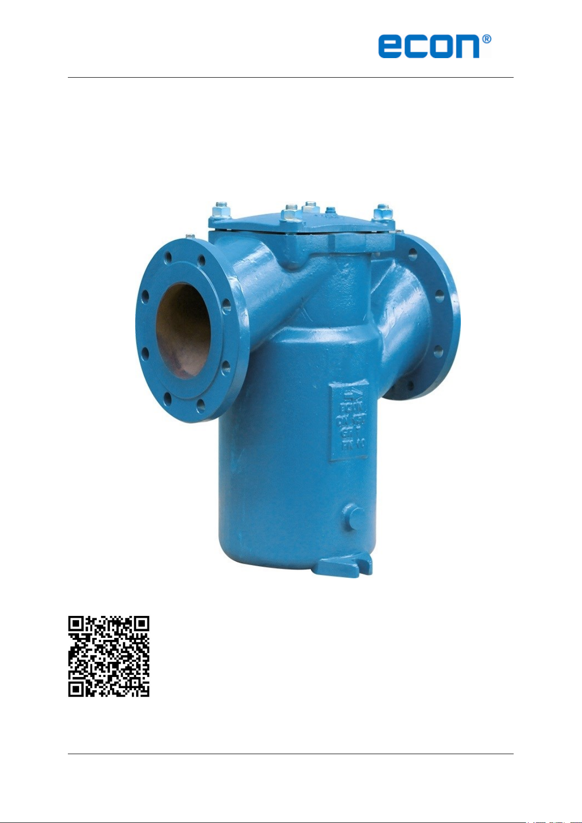
ECON BUCKET FILTER
Fig. 1096
Scan for manual
Operating and Instruction Manual for Bucket filter: Fig. 1096
ECON bucket filter Fig. 1096 www.eriks.com
Rev. 1
Page 2

Installation & Operation Manual
Proven Quality since 1892
Content
1. ERIKS operating companies
2. Product description
3. Requirements for maintenance staff
4. Transport and storage
5. Function
6. Application
7. Installation
8. Maintenance
9. Service and repair
10. Changing from mounted cover to clamped cover
11. Troubleshooting
12. Removal
1. ERIKS operating companies
ECON bucket filters are being delivered by several ERIKS operating companies on a worldwide
basis. In this manual these will be referred to as ‘ERIKS’, the individual terms of delivery of the
ERIKS operating company having executed the order are applicable.
2. Product description
The ECON bucket filters are designed according the information in our latest catalogue or see our
website www.eriks.com and should be used in accordance with the applicable pressuretemperature rating as stated on this website. ECON strainers are provided with casted markings
according to EN 19. The marking makes the identification of the strainers easier and contains:
- size (DN)
- nominal pressure
- body material marking
- heat numbers (when required)
- arrow, indicating the medium flow direction
- ECON logo
3. Requirements for maintenance staff
The staff assigned to assembly, operating and maintenance tasks should be qualified to carry out
such jobs and in any circumstance, ensure personal safety
4. Transport and storage
During transport and storage the filters should always be protected against external forces,
influence and destruction of the painting layer as well. The purpose of the painting layer is to
protect the filter against rust, during transport and storage. The strainers should be stored in an
unpolluted space and should also be protected against all atmospheric circumstances. There
should be taken care of the temperature and humidity in the room, in order to prevent condensate
formation.
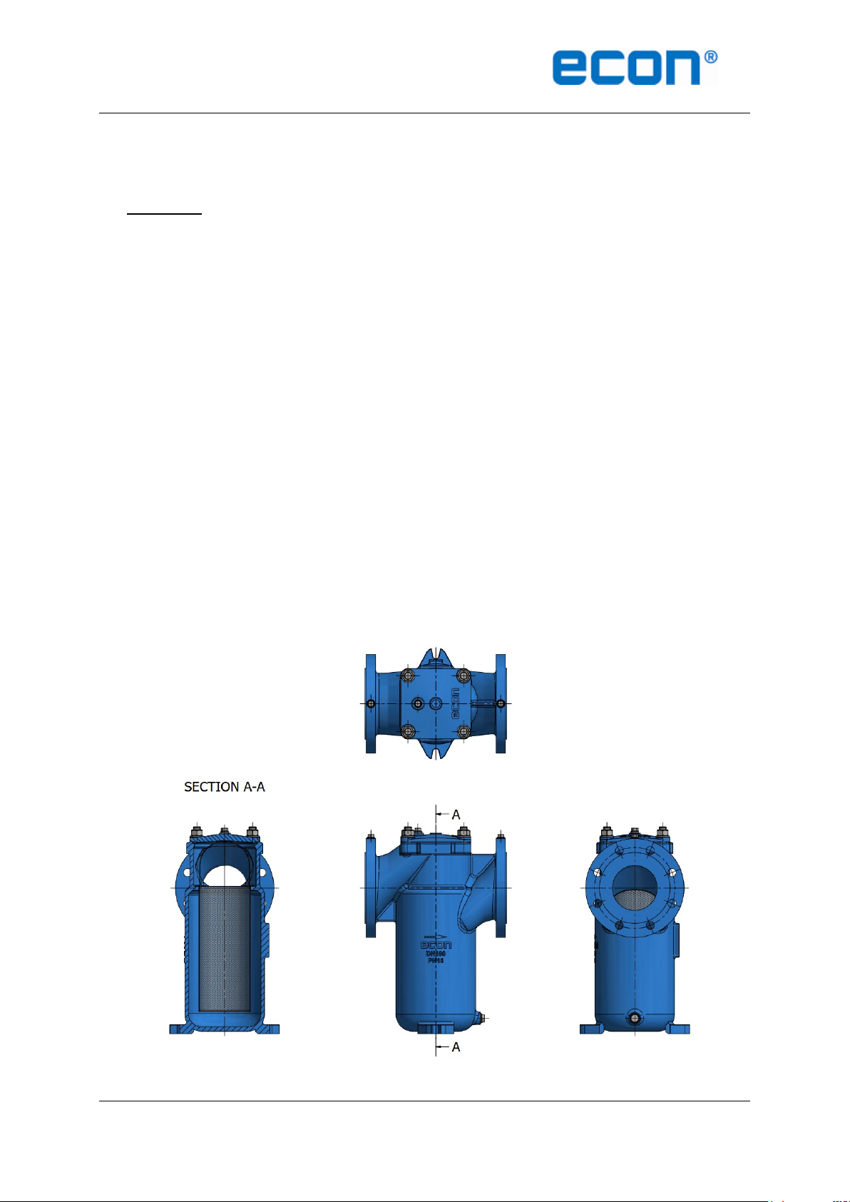
5. Function
ECON bucket filters are used to protect other pipeline components downstream from damage due
to debris and dirt in the system. The medium to be filtered flows through the filter insert from the
inside to the outside. The flow direction is marked on the body of the filter. The particles remain in
the filter and can be removed with the filter insert. The filter is only suitable for use in a horizontal
pipeline.
6. Application
ECON bucket filters are designed for standard operating conditions. The standard allowable
differential pressure/clogging rate for the insert is 1,5 bar and shall not be exceeded, this can lead
to equipment damage. For the use of extreme conditions e.g. aggressive or abrasive media, it is
recommended to mention this at the ordering stage, to verify whether the filter is suitable. The
installation designer is responsible for the filter selection, suitable for the working conditions. The
ECON bucket filter Fig. 1096 www.eriks.com
Rev. 1
Page 3
Installation & Operation Manual
Proven Quality since 1892
filters are unsuitable, without written permission of an ERIKS company, to apply for hazardous
media as referred into Regulation (EC) No 1272/2008.
7. Installation
During the assembly of the ECON bucket filters, the following rules should be observed:
- the filters should be checked before installation if they have not any defects caused by
transport and/or storage.
- make sure that the applied filters are suitable for the working conditions, medium used in
the plant and the right system connections, according to pressure and temperature limits
and that the insert is installed with the correct perforation/mesh.
- protective flange hole plugs must be removed
- bucket filters can only be used in liquid systems as MDO, oil, water and seawater and in a
horizontal pipeline, with enough clear necessary space above the filter for removing the
insert out of the filter.
- during fitting, the proper flow direction has to be considered.
- the filters must be stress free mounted between the flanges, supports must be arranged to
prevent any additional stress, caused by the weight of the filter or the pipeline.
- bolted joints on the pipeline must not cause additional stress resulted from excessive
tightening, user shall select proper bolts and gaskets according the working temperature,
working pressure and medium.
- the standard allowable differential pressure/clogging rate for the insert is 1,5 bar and shall
not be exceeded and can lead to equipment damage.
Operating instructions for startup.
- open the venting device on top of the filter until liquid escapes
- close venting device
- filter is ready for operation
ECON bucket filter Fig. 1096 www.eriks.com
Rev. 1
Page 4

Installation & Operation Manual
Proven Quality since 1892
8. Maintenance
Before starting any service jobs, make sure that the medium supply to the pipeline is cut off,
pressure was decreased to ambient pressure, the pipeline is completely ventilated and the plant is
cooled down. Always keep safety instructions in mind and take all personal safety precautions.
During maintenance, the following rules should be observed:
- always keep personal safety precautions in mind and always use appropriate protection
e.g. clothing, masks, gloves etc.
- be alert that the temperature still can be very high or low and can cause burns.
- check the strainer on all possible leaking possibilities.
- check if all bolts and nuts, are still fastened.
- the thickness of the body must be checked to ensure safety operation at an interval of at
least three months.
During cleaning the following steps have to be taken:
- relieve the pressure on the bucket filter by means of the venting device and drain unit.
- loosen the cover bolts and lift off the cover
- drain the filter through the drain unit to a level that is at least below the filterer insert
support.
- pull the filter insert upwards and out of the filter housing. The filter insert can now be
cleaned by careful blowing it out or blasting it with compressed air, steam, or water. If
necessary the filter insert must be soaked and cleaned in a suitable cleaning space. In
some circumstances optimum cleaning is achieved by means of ultrasound. For all
cleaning types ensure that the filter mesh is not damaged.
- when assembling the filter insert in the reverse sequence, check the sealing elements for
wear and replace them if necessary.
9. Service and repair
All service and repair jobs should be carried out by authorized staff, using suitable tools and user
shall use original gasket, bolt and nut of the same size and material as the original one.
- welding (repair) and drilling of the bucket filter is forbidden.
- it is forbidden to replace the bolt, nut or packing when the strainer is under pressure.
- tighten the hexagon nuts evenly crosswise in the there for standard order.
- after replacement of the gasket, bolts or nuts, it is necessary to check the strainer
operation and tightness of all connections. A tightness test should be carried out.
- after installation, the filter should be checked and maintained periodically at least every
3 months, depending on the medium.
10. Changing from mounted cover to clamped cover
- for DN15 – DN200 there is a combination cover available with clamp catch, for quick
release and easy installation of the cover after maintenance.
With the clamp on the cover and mounted behind the cams of the filter body, the cover
can be fixed by turning the bolt in the middle of the clamp clockwise till the cover is
secured. Please check if the cover is correct mounted on top of the body and bodyseal.
After checking, the lock nut of the bolt can be fasten.
When changing the bucket filter from bolted cover version to clamped cover version the
stud bolts and nuts can be forgotten.
Please note that the clamped version has a lower maximum working pressure,
depending on Nom. diameter and housing size.
ECON bucket filter Fig. 1096 www.eriks.com
Rev. 1
Page 5

Installation & Operation Manual
Proven Quality since 1892
Bolt with lock nut
Cam
Clamp
Filter body
Filter
ECON bucket filter Fig. 1096 www.eriks.com
Rev. 1
Page 6

Installation & Operation Manual
Problem
Possible cause
Corrective measures
No flow
Flange dust caps were not
removed
Remove dust caps
Little flow
Filter insert clogged
Clean/replace filter insert
Piping system clogged
Check piping system
Leakage between body and
cover
Cover bolts loose
Proper tighten cover nuts
Cover gasket failure
Replace cover gasket
Clamp connecting incorrect
Check clamp connection
Body and/or cover broken and
leaking
Water hammer
Careful operation to prevent
suddenly stopping pumping and
rapidly shutting
Broken because of freezing
Drain the water in the winter
when the filter is not used or
use proper isolation
Proven Quality since 1892
11. Troubleshooting
It is essential that the safety regulations are observed when identifying the fault.
12. Removal
All dismantled and rejected bucket filters cannot be disposed with household waste. The bucket
filters are made of materials which can be re-used and should be delivered to designated recycling
centres.
General warning:
General note for products which may be used for seawater:
Although our products can be used in seawater systems it should always be noted that, in case of
installation in a piping system made of materials which are frequently used because of their excellent
seawater resistance (e.g. Cunifer), large potential differences may occur possibly causing corrosion
which could permanently damage the proper functioning and integrity of our product.
A combination of different materials should always be mentioned prior to the purchase of our products
in order for us to give the best possible advice on a safe functioning.
General note for cast iron products:
Cast iron can be used for various applications, such as listed in our catalogue. It should however
always be observed, that frost (in combination with non drained products) may permanently damage
the proper functioning and integrity of our product.
ECON bucket filter Fig. 1096 www.eriks.com
Rev. 1
Page 7

Installation & Operation Manual
Proven Quality since 1892
ECON bucket filter Fig. 1096 www.eriks.com
Rev. 1
 Loading...