

Page 1
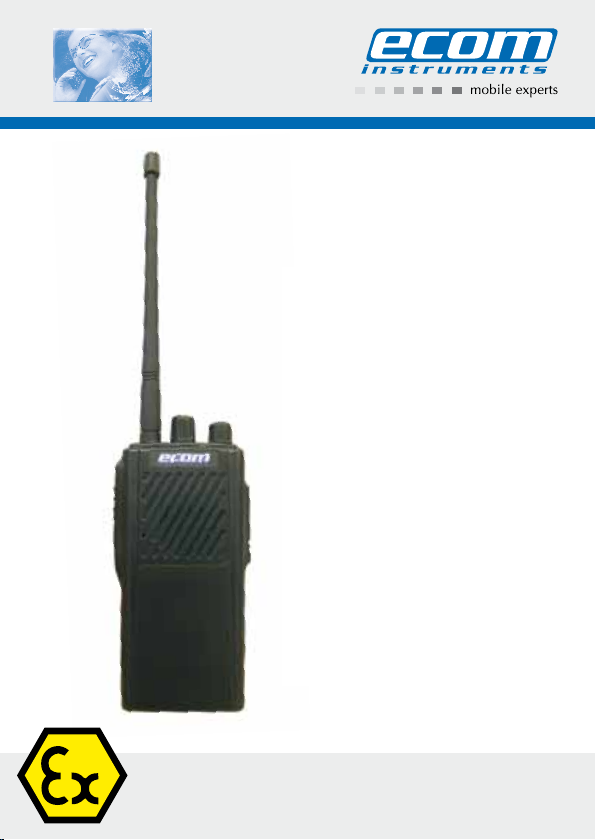
Ex-PMR 1000
Operating Instructions
Page 2

Table of Contents
1. Application 28
2. Safety instructions 28
3. Errors and load restrictions 28
4. Safety regulations 28
5. General safety instructions 29
6. Ex-data 31
7. Technical data 32
8. Functional description / operating information 32
8.1 Display and control elements, connections 33
8.2 Functions 34
8.3 Integrated Antenna 36
8.4 Getting started 36
8.4.1 Inserting the battery module 36
8.4.2 Basic functions 37
8.4.3 Changing the pre-programmed storage spaces 37
8.4.4 Checking the channel storage space settings 41
8.5 Accessories 43
9. Charging the battery module 43
9.1 General Information 43
9.2 LED display / Charging process 44
10. Legal Information 46
11. Repairs 46
12. Disposal 46
13. Cleaning, maintenance and storage 47
14. Warranty and liability 47
15. EC-Type Examination Certificate 49
16. EC Declaration of Conformity 54
Note:
The current operating instructions, EC Declaration of Conformity and the
Ex-certificate are available for download from the relevant product page under
www.ecom-ex.com; alternatively they can be requested directly from the
manufacturer.
27
Page 3

1. Application
The Ex-PMR 1000 is a radio unit that does not require registration in many
European countries (446 MHz range) for industrial use in potentially explosive
areas of zones 2 and 1 or 22 in accordance with Directive 1999/92/EC
(ATEX 137).
2. Safety instructions
These operating instructions contain information and safety regulations that
must be followed to ensure safe and reliable operation of the unit under the
described conditions. Failure to follow the information and instructions can
have dangerous consequences or may contravene applicable regulations.
Please read these operating instructions carefully before starting to use
the unit! In the event of any doubt or discrepancies (e.g. due to translation
or printing errors), the German version of these operating instructions shall
govern.
3. Errors and load restrictions
If there is any risk that the safety or integrity of the unit has been compromised, the unit must be taken out of operation immediately and removed from
the Ex-area without delay. Action must be taken to prevent the device from
being accidentally placed into operation again. We recommend that the unit
should be sent to the manufacturer to be examined.
The safety and reliability of the unit may be at risk if, for example:
- visible damage is evident on the housing.
- the unit has been subjected to excessive loads for which it is not designed.
- the unit has been improperly stored.
- the unit has been damaged in transit,
- inscriptions or lettering on the unit are illegible.
- malfunctions occur.
- permitted tolerances or threshold values have been exceeded.
4. Safety regulations
Any person using the unit must observe the standard safety regulations and
read the certificate to prevent incorrect operation or abuse of the unit.
The following additional safety regulations must also be observed:
- The unit must not be opened within the Ex-area.
28
Page 4

- The battery must only be changed outside the Ex-zone.
- Additional or spare batteries must not be carried in the Ex-area.
- Only the Ex-battery module Ex-AM PMR 1000 specified by the manufactu rer may be used.
- The use of other batteries is strictly prohibited and will result in termination
of Ex-protection.
- The battery must only be charged outside of the Ex-area with the designa ted charger LS PMR 1000 and the corresponding power supply unit
PS PMR 1000.
- Only the corresponding Remote Control Speaker Microphone Ex-HS 01
should be connected to the headset port inside the Ex-area.
- Only the corresponding EP1 earphones should be connected to the
Remote Control Speaker Microphone Ex-HS 01 inside the Ex-area.
- Only accessories approved by ecom instruments GmbH may be used
(siehe: www.ecom-ex.com)
- Accessories may only be exchanged outside the Ex-area.
- It must be ensured that the unit is not taken into zone 0, 20 or 21.
- Clean only with a damp cloth!
5. General safety instructions
5.1 Transport safety
NEVER use a hand-held radio unit while operating a vehicle. Park the vehicle
before answering a call or before placing a call yourself. To avoid having the
radio unit fly about in the event of a collision or a sudden braking manoeuvre,
do not place the radio unit on the front passenger’s seat or in a place where it
can become dislodged. Always remember the following:
Transport safety takes priority!
5.2 Operating environment
The particular regulations that apply to an area must be observed at all times.
The radio unit must always be turned off if the use of radio units is prohibited
or if it causes interference which may lead to hazardous situations. The device
must always be held in a normal operating position. Since parts of the radio
unit are magnetic, metal parts may be attracted to it.
To avoid metal parts being attracted to the radio unit, you should always
secure the device in a specially-designed holder. Do not allow credit cards
or other magnetic data carriers to come into close proximity to the radio unit,
since the data contained on these items could be deleted.
29
Page 5

5.3 Electronic devices
Today, most electronic devices are shielded from so-called RF (radio frequency) signals. It can happen, however, that some electronic devices are not
shielded from the RF signals of your radio unit.
5.3.1 Pacemakers
The following applies for persons with pacemakers:
- The general rule is to maintain a minimum interval of 20 cm between the
radio unit and the pacemaker when the radio unit is turned on.
- To keep the risk of possible disturbances as low as possible, we
recommend that you use the ear furthest from the pacemaker when
operating the unit.
- If you have cause to suspect that your pacemaker has been disturbed,
turn your radio unit off at once.
5.3.2 Hearing aids
It is especially important that persons who use hearing aids do not hold the
radio unit to the ear with the hearing aid. In the event of possible disturbances
with some types of hearing aids, please contact your local service partner.
5.3.3 Other medical devices
As is the case with other electronic devices as well, your radio unit may interfere with medical devices that are not adequately shielded. If you should need
information regarding sufficient shielding of a medical device against external
RF signals, please contact the respective physician or the manufacturer of the
medical device. To generally avoid malfunctions, you should turn your radio
unit off in all health care facilities if so requested by signs, placards or regulations.
Please note:
Devices which react sensitively to external RF signals are often used in hospitals and other health care facilities.
5.3.4 Respectively designated locations
You should turn your radio unit off in all places where such requests are fit-
ting and appropriate.
30
Page 6

5.4 Vehicles
5.4.1 Automobiles
Under certain circumstances, RF signals can have a negative impact on the
function of improperly installed or insufficiently shielded electronic systems
within your automobile (e.g. electronically controlled fuel injection, electronic
anti-lock braking systems, electronic speed regulator, air bag systems). You
can obtain information about your vehicle from your vehicle manufacturer
or his representative. To prevent disturbances, only skilled personnel should
install the radio unit in the vehicle. Faulty installation or maintenance can lead
to dangerous consequences. Please keep in mind that these mistakes may
result in the forfeiture of the valid warranty on your unit. We recommend regular inspection of all installed components of the radio unit equipment in your
vehicle. In vehicles with airbags, these airbags are filled with a great deal of
kinetic energy. To reduce the risk of injuries or malfunctions, you should not
mount any parts in the area claimed by the inflated airbag.
5.4.2 Airplanes
The use of radio units on airplanes is prohibited in most cases. Turn your
radio unit off before boarding the airplane. Since operation of a radio unit
on board an airplane can have dangerous consequences, non-compliance
with such instructions may result in the person acting contrary to instructions
being forbidden to use it and/or legal action could be initiated against him/
her.
5.5 Detonaters and detonating areas
To avoid possible interference with the detonating operation, you should take
your radio unit out of operation in the vicinity of electric detonators, in a detonating area or in environments with an appropriate instruction to "Turn off all
transmitting and receiving devices”. Follow all warnings and instructions.
6. Ex-data
EC-type examination certificate no.: ZELM 05 ATEX 0271
Ex-designation:
II 3 D Ex ibD 22 T130°C IP5x
II 2 G Ex ib IIC T4
Approved for Zones 2 and 1, device group II, gas group C potentially explosive gases, vapours or mist, temperature class T4.
Approved for zone 22, device group II, dust with increased risk of explosion, T130 °C.
31
Page 7
7. Technical data
Ambient temperature Ta: -20 °C ... +50 °C
Storage temperature: -20 °C ... +45 °C
Charging temperature: 0 °C ... +40 °C
Power supply: Ex-battery pack Ex-AM PMR 1000
Period of operation: approx. 13 hours (90% standby, 5%TX, 5%RX)
Charging time: approx. 4 hours
Dimensions: 126 x 64 x 42 mm
Frequency range: 446.00625 – 446.09375 MHz
Sensitivity: approx. 0.30 µV at 12 dB SINAD
Channels: 8
Channel grid: 12.5 kHz
Max. Transmission power: 0.5W ERP
NF – power output: max. 0.5 W
Weight: approx. 450g (including battery pack)
IP rating: IP 54
CE designation:
0678
Channel frequency table
Channel Frequency (MHz)
1 446.00625 5 446.05625
2 446.01875 6 446.06875
3 446.03125 7 446.08125
4 446.04375 8 446.09375
8. Functional description / operating information
Please take the time to carefully read through this owner’s manual to ensure
that you are familiar with all of the functions of your Ex-PMR 1000 and know
how to use them. For you own safety and information please read through the
information on the following pages.
Channel
0102
Frequency
(MHz)
32
Page 8

8.1 Display and control elements, connections
Antenna
Channel switch
This knob is turned to select channel storage spaces 1–S (channel S can be
programmed as a search run function) For pre-set channels and pilot tones,
see table: "Default Values of Channels” under Item 8.4.4
LED display
The red LED display illuminates when transmitting. The green LED display illuminates when receiving. The red LED flashes when the battery voltage is low.
ON/OFF and volume control
Turn the knob clockwise to turn the device on. To turn the device off, turn it
counter clockwise until a signal tone sounds. When the radio unit is turned
on, this knob is used to control the volume.
Loudspeaker / Microphone
PTT (Push to Talk)
PTT is pressed for transmitting and PTT is released for receiving.
33
Page 9

Monitor key
Press the MONI key to monitor activities on the current channel.
Loudspeaker/microphone sockets
When these accessory sockets are not being used, cover them up with the
protective cap.
Belt clip / Ex-battery module / Battery locking mechanism
8.2 Functions
All 8 channels are very easy to switch
The Ex-PMR 1000 can be operated on all 8 channels.
FM for crystal-clear connections
Transmission is in frequency modulation (FM), which ensures lifelike and lowdisturbance playback, as with the UKW.
16 channel storage spaces
So you always have sufficient fixed alternatives for your radio partners.
CTCSS & DCS
With CTCSS/DCS, you can ignore unwanted calls from other parties on the
same channel. When CTCSS/DCS is set, the user can only receive the calls
on the same channel with the same CTCSS/DCS.
Please observe: Although you can ignore unwanted calls with CTCSS/DCS,
this does not mean that your conversations are private.
TOT Switch-off Timer
The Time-out function is used so as not to use the same channel too long and
to prevent damage to the device due to continuous transmission.
If the transmission exceeds the prescribed time (60 s), it is interrupted and an
alarm sounds. This is stopped by releasing PTT. Press PTT again to transmit.
TOT-Reset Time
If the send pause is longer than the set time (TOT-Reset Time), the TOT –
shut-off timer will be reset. If the send pause is shorter than the set time (TOTReset Time), the TOT – shut-off timer will be added on.
The function is deactivated. Changing the setting is only possible with optional
software.
34
Page 10

TOT – Rekey Time
After activating the TOT – shut-off timer, the send function is blocked until the
pre-set time (TOT-Rekey Time) has lapsed.
The function is deactivated. Changing the setting is only possible with optional
software.
TOT – Alert Time
An alarm sounds at a programmed point in time before activating the TOT
– shut-off timer. Subsequent send interruption by TOT – shut-off timer. The
function is deactivated. Changing the setting is only possible with optional
software.
Monitor
Radio activities on the current channel can be monitored by pressing and holding the ”MONI” key. This is especially useful for setting the volume or if you
are receiving a weak signal.
When holding the "MONI” key, the green LED display illuminates.
Channel search run
Set the channel switch to "S”; the radio unit then only automatically records
the channels that have been programmed for search run in channels 1-15. If
a signal is detected on a channel, the radio unit stops on this active transmission channel.
Preferred channel search run
Each programmed channel can be set as a preferred channel. The radio
unit records the preferred channel at regular intervals and interrupts a nonpreferred channel. If a signal is detected on the preferred channel, the radio
unit automatically goes to this channel.
The function is deactivated. Changing the setting is only possible with optional
software.
Revert Channel Search Run
This function brings you to the right channel, while you are initiating a call
during channel search run. Press PTT and the unit will stop search run and
transmit on the revert channel (channel 1).
Busy Channel Lockout
If the selected channel is set as "Busy Channel Lockout" and being used by
35
Page 11

others, a warning signal sounds when activating PTT. The signal is not transmitted. The warning signal is stopped by releasing PTT. When the channel is
free, press PTT again to transmit.
The function is deactivated. Changing the setting is only possible with optional
software.
Battery saving function
This function can be used to save current when no signal is being received
and none of the functions are being carried out (when no keys are being
pressed and no knobs are being turned). The battery saving function switches
on when there is no radio activity on a channel for 25 seconds and no functions are being carried out. As soon as a signal is received or the device is
otherwise being used, this function switches off.
Low Battery Warning
The "Low Battery Warning” Imeans that you must charge or replace the battery module. If the battery module goes below a pre-set voltage during operation, the red LED display flashes. If an alarm sounds, the transmission process
is aborted. Please charge the battery module or replace it with a replacement
module.
Sockets for loudspeaker and microphone
A headset or microphone/loudspeaker combination can be connected to the
sockets on the side of the device. Please note: only accessories approved by
ecom instruments GmbH may be connected.
8.3 Integrated Antenna
The Ex-PMR 1000 comes with a flexible, integrated rubber antenna and only
this antenna may be used! This integrated antenna is connected together
non-detachably with the handheld radio telephone (radio unit).
Note:
- Never carry the radio unit by the integrated antenna!
- Connecting a different antenna is punishable!
8.4 Getting started
8.4.1 Inserting the battery module
First insert the Ex-battery module Ex-AM PMR 1000 included in the scope of
supply into the gui
guides until the battery locking mechanism locks in position on the radio unit.
36
de rails of the Ex-PMR 1000. Slide the battery module on the
Page 12

8.4.2 Basic functions
1. To switch on, turn the ON/OFF or volume control clockwise until a signal
tone sounds.
2. To control the volume, turn the ON/OFF or volume control while simulta-
neously holding down the monitor key.
3. To select a channel, turn the channel switch to select the respective
channel.
4. To transmit, press and hold PTT and speak into the microphone in a normal
voice. Hold the microphone about 5 cm from your mouth.
5. Release PTT to receive.
Please observe: If the battery voltage is too low, the transmission process will
stop and the red LED display will flash. Further information can be found at:
8.2 Functions - Low Battery Warning
8.4.3 Changing the pre-programmed storage spaces
8.4.3.1 Channels
You can change the frequency allocation of the 16 pre-programmed channel
storage spaces. Select a value from 0 – 8 to change the frequency allocation
of the selected channel.
Please observe: After programming is complete, switch the unit off and back
on again, so that it is back in the operating mode.
If "0” is selected, the programmed channel is empty (no frequency).
1. Turn the radio unit on while pressing PTT and the monitor key.
Only release PTT and the monitor key when the LED display illuminates
in orange.
2. Press PTT until the LED display changes from orange to green and a signal
tone sounds, which means that the radio unit is in the frequency setting
mode.
3. Select the desired channel using the channel switch.
37
Page 13

4. Using PTT, select the frequency number from the 9 different numbers 0-8.
Each time you press it, the frequency number changes accompanied by a
signal tone.
Operation Channel number Signal tone
Press and hold
PTT for 2 seconds
Press PTT one time 1 .
Press PTT two times 2 ..
Press PTT three times 3 ...
Press PTT four times 4 ....
Press PTT five times 5 .....
Press PTT six times 6 -.
Press PTT seven times 7 -..
Press PTT eight times 8 -...
Please observe:
Select channel number "0" when not selecting any channel. To do so, press
PTT for about 2 seconds until a 1-second long signal tone sounds.
If PTT is pressed more often than 8 times, a signal tone sounds and no value
is selected.
5. The respective signal tone of the selected number sounds after 2 seconds.
6. Press the monitor key to end this setting. The red LED flashes two times.
Press the monitor key again to confirm the signal tone of the desired number.
7.
8. Program another channel as described in steps 3 through 7 above.
0 1 second tone
Example: Changing a channel storage space (11) to channel number 8
1. Select channel storage space 11 in the set mode.
2. Press PTT 8 times to select 8 as the channel number. Each time you
press it, a signal tone will sound.
3. After 2 seconds, one long and three short signal tones sound, to confirm
your selection of channel number 8.
4.
Press the monitor key to complete the setting. The red LED display flashes
38
Page 14

two times.
5. Press the monitor key again. One long and three short signal tones confirm
that channel number 8 has been selected.
8.4.3.2 Pilot tones
Please observe:
After programming is complete, switch the unit off and back on again, so that
it is back in the operating mode.
All of the CTCSS/DCS pilot tones are listed in the following table.
After confirmation of a signal number ≥ 10, a short trace occurs between the
tens and the units.
No. CTCSS/DCS No. CTCSS/DCS No. CTCSS/DCS No. CTCSS/DCS
0 OFF 25 156,7 Hz 50 D072 75 D261
1 67,0 Hz 26 162,2 Hz 51 D073 76 D263
2 71,9 Hz 27 167,9 Hz 52 D074 77 D265
3 74,4 Hz 28 173,8 Hz 53 D114 78 D271
4 77,0 Hz 29 179,9 Hz 54 D115 79 D306
5 79,7 Hz 30 186,2 Hz 55 D116 80 D311
6 82,5 Hz 31 192,8 Hz 56 D125 81 D315
7 85,4 Hz 32 203,5 Hz 57 D131 82 D331
8 88,5 Hz 33 210,7 Hz 58 D132 83 D343
9 91,5 Hz 34 218,1 Hz 59 D134 84 D346
10 94,8 Hz 35 225,7 Hz 60 D143 85 D351
11 97,4 Hz 36 233,6 Hz 61 D152 86 D364
12 100,0 Hz 37 241,8 Hz 62 D155 87 D365
13 103,5 Hz 38 250,3 Hz 63 D156 88 D371
14 107,2 Hz 39 D023 64 D162 89 D411
15 110,9 Hz 40 D025 65 D165 90 D412
16 114,8 Hz 41 D026 66 D172 91 D413
17 118,8 Hz 42 D031 67 D174 92 D423
18 123,0 Hz 43 D032 68 D205 93 D431
19 127,3 Hz 44 D043 69 D223 94 D432
20 131,8 Hz 45 D047 70 D226 95 D445
39
Page 15

21 136,5 Hz 46 D051 71 D243 96 D464
22 141,3 Hz 47 D054 72 D244 97 D664
23 146,2 Hz 48 D065 73 D245 98 D723
24 151,4 Hz 49 D071 74 D251 99 D754
1. Turn the device on while holding down PTT and the monitor key at the
same time. Only release PTT and the monitor key when the LED display
illuminates in orange.
2. Press the monitor key until the LED display changes from orange to green
and a signal tone sounds, which means that the radio unit is changing to
the CTCSS/DCS set mode.
3. Select the desired channel storage space using the channel switch.
4. Select the "tens” digit of the signal number between 0-9 by pressing PTT.
Each time you press it, the signal number changes and is accompanied by
a signal tone.
5. The respective signal tone of the selected number sounds after 2 seconds.
6. By pressing PTT, select the unit of the signal number from 10 different
numbers 0-9. Each time you press it, the signal number changes and is
accompanied by a signal tone.
Operation Number Signal tone
Press PTT and hold for 2 seconds 0 1 second tone
Press PTT one time 1 .
Press PTT two times 2 ..
Press PTT three times 3 ...
Press PTT four times 4 ....
Press PTT five times 5 .....
Press PTT six times 6 -.
Press PTT seven times 7 -..
Press PTT eight times 8 -...
Press PTT nine times 9 -....
40
Page 16

Please observe:
In order not to select any pilot tone, select the pilot tone number "0”. Press
PTT and hold it for approx. 2 seconds, until a one-second tone sounds.
If PTT is pressed more often than 9 times, a warning tone sounds and no
value is selected.
7. The respective signal tone of the selected number sounds after 2 seconds.
8. The setting is completed by pressing the monitor key.
The green LED display flashes two times.
9. Pressing the Monitor key again confirms the signal tone of the selected
number.
10. Program another channel just the same as in the above steps 3-9.
Example: Changing a channel storage space (2) with CTCSS – pilot tone No. 25
1. Select channel storage space 2 in the CTCSS/DCS set mode.
2. Press PTT 2 times to select 2 for the "tens” digit.
3. After 2 seconds, 2 short signal tones confirm that 2 has been selected.
4. Press PTT 5 times to select 5 for the "units” digit. Each time you press it,
a signal tone will sound.
5. After 2 seconds, 5 short signal tones confirm that 5 has been selected.
6. Press the monitor key and the green LED display flashes two times.
7. Press the monitor key again. Two short signal tones will sound and - after a
short pause - 5 short signal tones, to confirm the selection of 25.
8.4.4 Checking the channel storage space settings
You can check the settings of your radio unit.
Please observe:
After checking is complete, switch the unit off and back on again, so that it is
back in the operating mode. No signal tone will sound if "0” is selected for the
"tens” digit.
1. Turn on the unit while pressing the PTT key. The radio unit goes into the
check mode.
2. Select the channel storage space which you would like to check.
3. Press PTT and the signal tone sounds (that is, when channel number 8 is
set, one long and three short signal tones sound).
41
Page 17

4. Press the Monitor key and a signal tone sounds (that is, when pilot tone 25
is set on the channel, two short signal tones and after a short pause, five
additional tones will sound).
5. Turn the unit off when the check is complete.
Confirming the signal tone
Number Signal tone Number Signal tone
0 1 second tone 5 .....
1 . 6 -.
2 .. 7 -..
3 ... 8 -...
4 .... 9 -....
Default values of the channel
Channel number Frequenz CTCSS / DCS
1 1 (446,00625) 0 (OFF)
2 2 (446,01875) 0 (OFF)
3 3 (446,03125) 0 (OFF)
4 4 (446,04375) 0 (OFF)
5 5 (446,05625) 0 (OFF)
6 6 (446,06875) 0 (OFF)
7 7 (446,08125) 0 (OFF)
8 8 (446,09375) 0 (OFF)
9 1 (446,00625) 1 (67,0 Hz)
10 1 (446,00625) 39 (D023)
11 2 (446,01875) 1 (67,0 Hz)
12 2 (446,01875) 39 (D023)
13 3 (446,03125) 1 (67,0 Hz)
42
Page 18

14 3 (446,03125) 39 (D023)
15 4 (446,04375) 1 (67,0 Hz)
16 (S) search run
8.5 Accessories
8.5.1Approved accessories within the Ex-area
Battery compartment:
- Battery pack Ex-AM PMR 1000
Headset connection:
- ExTRA 300 A headsets
- Microphone/loudspeaker combination Ex-HS 01
Ex-HS 01 earphone connection:
- Earphones EP 1
Additional accessories are available at: www.ecom-ex.com
8.5.2 Charger
The battery must only be charged outside of the Ex-area with the designated
charger LS PMR 1000 and the corresponding power supply unit PS PMR 1000.
9. Charging the battery module
9.1 General Information
Turn the radio unit off before charging the battery module. Using the device
while charging can result in charging problems.
Use only the approved charger LS PMR 1000 and the corresponding power
supply unit PS PMR 1000 for charging. The battery may only be charged
outside the Ex-area! The battery module can be charged together with the
Ex-PMR 1000 or separately (see illustration). Please observe:
Charging temperature range: 0 °C ... +40 °C.
43
Page 19

9.2 LED display / Charging process
An LED display is located on the front side of the charger to indicate the
charge status.
ERROR
CHARGING
FULLY CHARGED
If the charger is connected to the power supply unit, The LED will not illuminate. When an Ex-PMR 1000 with mounted or individual Ex-AM PMR 1000 is
inserted, the LED illuminates in red (CHARGING).
Charging is complete after about 4 hours and the LED illuminates green
(FULLY CHARGED).
In case of failure, the LED flashes red (ERROR) and the Ex-PMR 1000, or the
battery module, must be removed from the charger immediately. The battery
module and charger should be sent off to ecom instruments GmbH for inspection.
44
Page 20

Battery care
- The battery should be completely charged before use.
- Note that the maximum capacity of the battery is achieved only after about
six charging and discharging cycles.
- Since the performance of batteries declines over time, they should be
completely discharged occasionally to maintain their full capacity. When
doing this, leave the unit turned on until it turns itself off. Subsequently fully
charge the battery pack Ex-AM PMR 1000 outside of the Ex-area.
Battery replacement
- Only the approved battery module Ex-AM PMR 1000 may be used!
- Please ensure that all used batteries are properly disposed of in an
environmentallyfriendly manner.
Note:
Please use only the LS PMR 1000 charger to charge the Ex-battery module
Ex-AM PMR 1000!
High quality lithium-ion batteries are used in your Ex-PMR 1000. These batteries have numerous advantages in everyday use, such as a low weight and
high capacity in a nevertheless compact construction. In addition these batteries also exhibit practically no memory effect.
However, these batteries are susceptible to a natural ageing process which
impairs their functionality. Modern batteries today have a lifespan of around
500 charge cycles, which, when used daily, corresponds to a service life of
approximately 2 years. The ageing process increases rapidly after this period,
which means that the batteries are deemed technically defective after 500
charge cycles. Moreover, the batteries could blow up and cause irreparable
damage to your device in a worst case scenario.
For this reason rechargeable batteries with lithium cells should be replaced
after 2 years at the latest or after reaching a battery capacity that is 50% of its
initial value.
Note: The battery used in this unit poses a fire hazard and can cause chemical injuries if it is used improperly. Neither the battery nor the battery
cells should be opened or disassembled and they should not be burned or
exposed to temperatures exceeding 100°C.
45
Page 21

10. Legal Information
No registration – no fees
Your radio unit is approved for short-range radio in many European countries
without requiring registration or fees.
The handheld radio telephones (radio units) in a frequency range of
446.00625 – 446.09375 MHz are intended for the transmission of speech.
Only handheld radio units with integrated antennas may be used.
Please also observe the respective directives and telecommunications laws
which are in effect for your specific country.
11. Repairs
Repair work is subject to the nationally valid regulations and directives. We
therefore recommend that such work be performed by ecom instruments
GmbH, Germany, as all repairs must be examined to ensure functional safety.
12. Disposal
Old electrical equipment and „historic“ old electrical equipment from ecom
instruments GmbH will be disposal obligation and disposed of at no cost in
accordance with the EC Directive 2002/96/EC and the German Electrical and
Electronic Equipment law of 16/03/2005. The costs of the transport of the
equipment to ecom instruments GmbH are borne by the sender.
In accordance with Article 1, Section 18 and Article 2 of the Act revising the
law of Waste-Related Product Responsibility for Batteries and Accumulators
(Gesetz zur Neuregelung der abfallrechtlichen Produktverantwortung für Batterien und Akkumulatoren) dated 25 June 2009, we are obligated to provide the
following information.
Your device contains a rechargeable lithium battery.
Depleted batteries or rechargeable batteries that can no longer be recharged should never be disposed of along with normal or household waste.
Old batteries can contain harmful substances that are hazardous to health
and damaging to the environment. Please return the batteries/rechargeable
batteries. Return is free of charge and required by law. Please only dispose of
discharged batteries in the designated containers and tape the terminals of
lithium batteries.
46
Page 22

Note: The battery used in this unit poses a fire hazard and can cause chemical
injuries if it is used improperly. Neither the battery nor the battery cells should
be opened or disassembled and they should not be burned or exposed to
temperatures exceeding 100 °C.
If the battery needs to be disposed of, it can be removed as described under
point (8.4.1). The disposal regulations specified above are also applicable for
old devices.
All batteries and rechargeable batteries can be recycled. Precious raw materials such as iron, zinc and nickel can therefore be reused.
The symbol
Batteries and rechargeable batteries should not be disposed of along with
normal or household waste.
13. Cleaning, maintenance and storage
- Only use a suitable cloth or sponge to clean the unit. Do not use solvents or
abrasive cleaning agents to clean the unit.
- We recommended having the function and the accuracy of the unit checked
by the manufacturer every two years.
- The storage temperature should be within the permitted ranged
of -20 °C to +45 °C.
- When the unit is not in use, the accessory sockets should be covered with
the protective cap.
14. Warranty and liability
Under the general terms and conditions of business, ecom instruments GmbH
offers a 2-year warranty for function and materials on this product under the
specified operating and maintenance conditions. Not covered are all wearing
parts (e.g. batteries, sensors, displays, lamps, etc.) as well as calibrations.
We give a manufacturer's warranty of six months especially for the supplied
Ex-batteries.
This warranty does not extend to products that have been used improperly,
altered, neglected, damaged by accident or subjected to abnormal operating
conditions or improper handling.
In the event of a warranty claim, the faulty device should be sent in. We reser-
has the following meaning:
47
Page 23

ve the right to readjust, repair or replace the unit.
The above warranty terms represent the sole rights of the purchaser to compensation and apply exclusively and in place of all other contractual or statutory warranty obligations. ecom instruments GmbH does not accept liability
for specific, direct, indirect, incidental or consequential damages or losses,
including the loss of data, regardless of whether they are caused by breach of
warranty, lawful or unlawful actions, actions in good faith or other actions.
If in certain countries the restriction of statutory warranty and the exclusion
or restriction of incidental or consequential damages is unlawful, then it may
be possible that the above restrictions and exclusions do not apply for all
purchasers. If any clause in these warranty terms should be found to be
invalid or unenforceable by a competent court, then such a judgement shall
not affect the validity or enforceability of any other clause contained in these
warranty terms.
48
Page 24
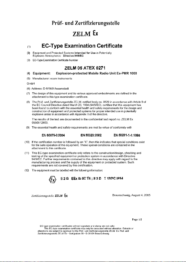
15. EC-Type Examination Certificate
49
Page 25

Prüf- und Zertifizi erungsstelle (Test and Certification Body)
ZELM Ex
First addition
(addition in accorda nce with EC Directive 94/9 Annex III Clause 6)
to the EC type- examination certificat e
ZELM 05 ATEX 0271
Device: Explosion-proof ha ndheld two-way radio, Type Ex-PMR 1000
Manufacturer: ecom Instrument s GmbH
Address: D-97959 Assams stadt
Description of the a ddition
The first addition to the EC type-examination certificate particularly conc erns the internal design
without significant modifications to the circuit-board layout.
The tec hnical data and id entification as well as the information provided in the EC typeexamination certificat e remain unchanged.
Test Report No.
ZELM Ex 1500515433
Special conditions
Not applicable
Fundamental safety and health requirements
The fundamental s afety and health requirements a re fulfilled through compliance with
EN 60079-0 : 2004 EN 50020: 20 02 EN 50281-1-1 : 1998
Certification Body Z ELM Ex Braunschweig, 10.0 1.2006
((Signature, stamp: T est and Certification Body ZEL M Ex))
Dipl.-Ing. Harald Zel m Page 1 of 1
EC type-ex amination certificates without signatur e and without stamp are not valid. This EC typeexamination certificate may only be distribute d with out c hange. Excerpts or changes must be
approved by the Test and Certification Body ZELM Ex .
Prüf- un d Zertifizierungsstelle (Test and Certification Body) ZEL M Ex * Siekgraben 56 * D-38124
Braunschweig, Ger many
50
Page 26

51
Page 27

Prüf- und Zertifizierungsstelle
(Test and Certification Body)
ZELM Ex
Translation
1st A ddend um
(Add end um i n ac cord anc e w ith EC d irec tiv e
4/ 9, ap pen dix I II nu mber 6)
9
to E C t ype ap pro val test
xpl osio n-pro tec ted h andh eld r adio Ex -P
Dev ice :
Manufactu
rer:
A
ddr es
s:
T
he 1 st ad dend um to the E C typ e app rova l tes t ce rti fic ate p art icul arl y
on cer ns inte rna l desi gn cha ng
c
he PCB lay out.
t
he te ch nica l dat a and t he lab elin g, as we ll as th e indi cat ions i n t he EC ty pe
T
ppr ova l te st cer tifi c
a
Test report no.
1
5005 15433
S
pe cia l co ndi tion s
ppl ica ble
a
B
asi c h eal th and saf ety requ irem ent s
T
he b asic h eal th a nd saf ety r equ irem ent s are m et by v irtu e of co nfor man ce
it h
w
er tifi zie rung sste lle
Z
(
Cer tif ica tion Bo dy)
EL M ex
Z
E
000
1
co m in stru men ts G mbH
e
-9
7959
D
ssa mst adt
A
at e, r ema in u nch ang ed.
Z ELM Ex
no t
E
N 6
0079 -0:
004
2
c
er tif ica te
ZE LM 05 AT EX 02 71
MR
es an d does no t invo lve sig nifi can t cha nges t o
EN 50020 : 200 2
N 5
E
998
1
0281 -1-1:
52
Bru nsw ick , 10 .01.06
EC t ype app rova l te st c ert ific ate s wi thou t a sign atur e and stam p ar e not vali d. Th is EC
ype app rova l te st c ert ific ate may on ly be ci rcu lat ed w itho ut a lter atio n. !
t
" Pr üf #
Prüf - und Z erti fizi eru ngsst elle ( Test a nd Ce rtif ica tion B ody) Z ELM Ex • Siek gra ben 5 6 • D 38124 Br aun sch weig
" !
age 1 o f 1
P
Page 28

2nd Addend um
(Addendum in accordance with EC directive 94/9, appendix III number 6)
Tr ans latio n
to EC ty pe ap proval test cer tifica te
ZELM eX
ZELM 05 ATEX 0271
Device:
Manufacturer:
Address:
Description of the addendum
The 2nd addendum to the EC type approval test certificate relates to the Ex-PMR
changes to the internal configuration, updates to existing standards and a change of the certification for dust approva l to "protection by
intrinsic safety - iD".
The "electrical data", includ ing the perm itted ambient tem perature range, as well as the information specified in the EC type approval test
certificate remain unaffected and a re also applicable for this 2nd addendum.
In the future the Ex-PMR
addendum and designated as follows:
Ignition protection class / designatio n:
The electrical d ata and all other specifications, as w ell as the details specified in the EC type approval test certificate remain unaffe cted and
shall continue to apply.
Test report no. ZELM Ex
1660812675
Basic health and safety requirements
Furthermore, the basic health and safe ty requirements are met by virtue of conformance with:
Brunswick, 04.05.09
Zertifizierungsstelle (Certification B ody) ZELM ex Dipl.-Ing. Harald ZELM ex
Page 1 of 1
ZELM ex
Prüf- und Zertifizierungsstelle (Test and Certification Body) • Siekgraben 56 • D-38124 Braunschweig
EC type approval test certificates without a signature and stamp are not valid. This EC ty pe approval test certificate may only be circulated without alteration. Extracts or alterations are subject
to approval by the Prüf- und Zertifizierungsstelle (Test and Certification Body) ZE LM ex
Explosion-protecte d handheld radio Ex-PMR 1000
ecom instruments GmbH
D-97959 Assamsta dt
1000 exp losion-protected handheld radio and considers
1000 explosion-protected handheld radio may also be manufactured in accordance with this 2nd
II 2 G Ex ib ll C T4
II 3 D Ex ib D2 2 T1 30 °C IP5x
EN 60079-0:2006
EN 60079-11:2007
EN 61241-0:2006
EN 61241-11:2006
53
Page 29

16. EC Declaration of Conformity
ecom instruments GmbH hereby declares that the unit meets all underlying
requirements of the European Directive R&TTE 1999/5/EC.
Further details relating to the declaration of conformity can be found at the
following Internet address:
http://www.ecom-ex.com in the Product Download area.
54
Page 30

Kommunikation
Mobile Computing
Portable Handlampen
Mess- & Kalibriertechnik
©
Copyright
Der Inhalt dieses Dokuments darf ohne vorherige schriftliche Genehmigung durch die ecom
instruments GmbH in keiner Form, weder ganz noch teilweise vervielfältigt, weitergegeben, verbreitet oder gespeichert werden.
Der Inhalt dieses Dokuments wird so präsentiert, wie er aktuell vorliegt. Die ecom instruments
GmbH übernimmt weder ausdrücklich noch stillschweigend irgendeine Gewährleistung für die
Richtigkeit oder Vollständigkeit des Inhalts dieses
schränkt auf die stillschweigende
bestimmten Zweck, es sei denn, anwendbare Gesetze oder Rechtsprechungen schreiben zwingend eine Haftung vor. Die ecom instruments GmbH behält sich das Recht vor, jederzeit ohne
vorherige Ankündigung Änderungen an diesem Dokument vorzunehmen oder das Dokument
zurückzuziehen.
Copyright© 2010 ecom instruments GmbH.
The contents of this document, either in part or in their entirety, may not be reproduced, forwarded, distributed or saved in any way without ecom instruments GmbH prior written consent.
The contents of this document are presented as they currently exist. ecom instruments GmbH
does not provide any express or tacit guarantee for the correctness or completeness of the
contents of this document, including, but not restricted to, the tacit guarantee of market suitability or fitness for a specific purpose unless applicable laws or court decisions make liability
mandatory. ecom instruments GmbH reserves the right to make changes to this document or to
withdraw it any time without prior notice.
2010 ecom instruments GmbH.
Dokuments, einschließlich, aber nicht be-
Garantie der Markttauglichkeit und der Eignung für einen
Communication
Portable Lighting
Mobile Computing
Measuring & Calibration
PA000223 / 1500 / 01/2010
WEEE-Reg.-Nr. DE 934 99306
0260AL01A02 01/10 Änderungen vorbehalten! Subject to change without notice!
ecom instruments GmbH · Industriestr. 2 · 97959 Assamstadt · Germany
Tel.: + 49 (0) 62 94 / 42 24 0 · Fax: + 49 (0) 62 94 / 42 24 100
E-Mail: sales@ecom-ex.com · www.ecom-ex.com
 Loading...