

Page 1

Operating Instructions
Page 2

Page 2
ecom-
J2KN
pro
TECH
Index Page
Important hints 4
1. Instrument design
1.1. Basic module 6
1.2. Control module 7
2. Gas flow scheme 8
3. 2-stage Peltier cooler 9
4. Heated sampling system 10
5. Converter (option) 11
6. Power supply 13
7. Radio communication basic/control module 14
8. Data record 15
9. Starting 16
10. Input or selection of combustion plants 18
11. Flue gas analysis
11.1. Gas analysis 21
11.2. Flow measurement (option) 25
11.3. Pressure measurement (option) 26
11.4. Soot dot...Oil trace (option) 27
11.5. Measurement record and printout 29
11.6. Mean value measurement 30
11.6. After measurement 32
12. Adjustments 33
13. Control 39
14. Data processing
14.1. Communication 40
14.2. Automatic Measurement 41
14.3. Data logger 42
14.4. Data logging with DASNT2 43
14.5. Data processing with DAS5 43
14.6. Data processing with App 44
15. Diagnostics
15.1. Fault diagnostic 45
15.2. dT-measurement 47
16. Maintenance tips 48
17. Technical data 52
18. FAQ 53
Page 3

ecom-
J2KN
pro
TECH
Page 3
___________________________
Congratulations!
With your purchase you have decided on a high-quality product of
ecom GmbH.
Get to know the product before you start using it while reading carefully the following instructions of use and the safety indications. Use
the product only as described and only for the given areas of application in order to ascertain its longevity.
___________________________
Page 4
Page 4
ecom-
J2KN
pro
TECH
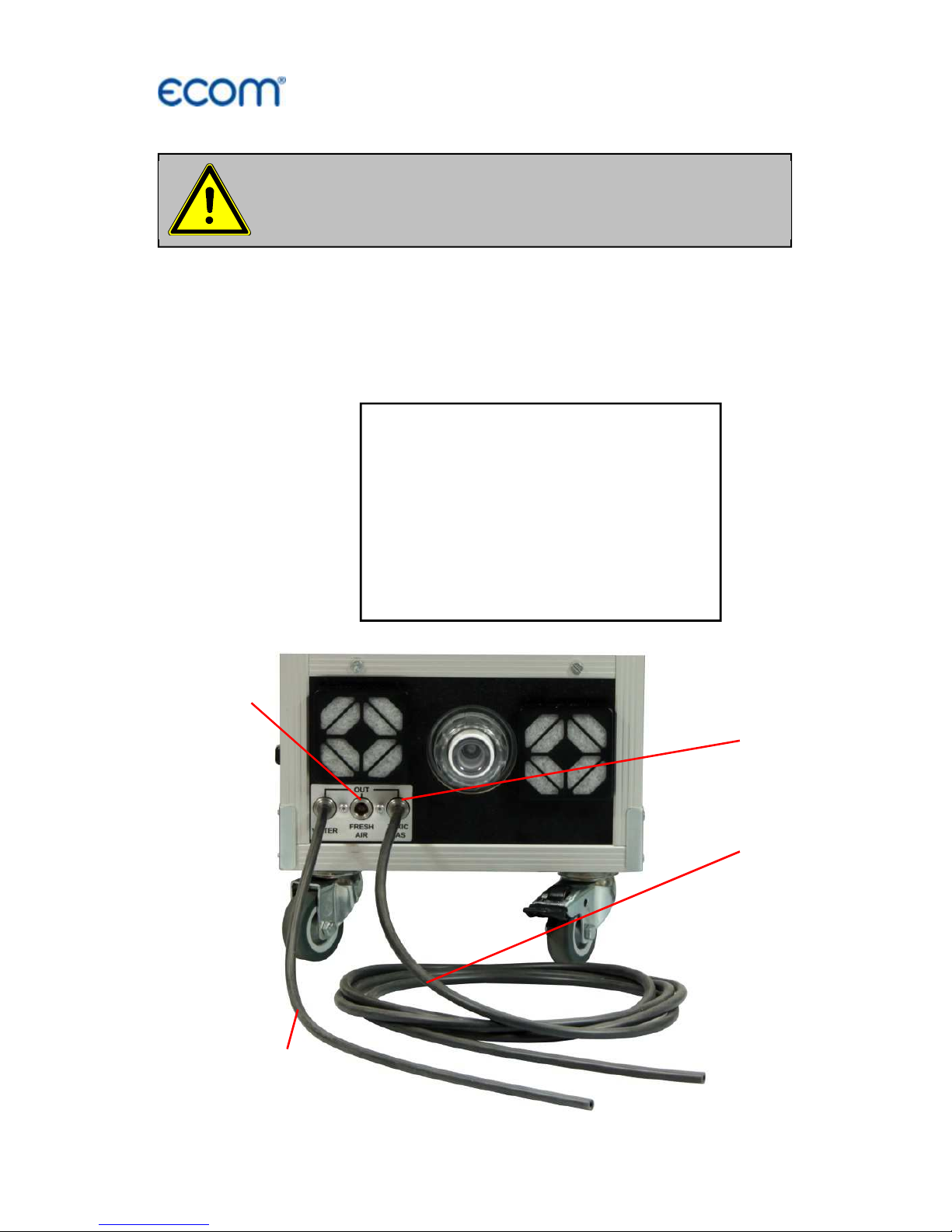
Important hints
To exclude any risk to persons, it is necessary to connect the sample
gas outlet (TOXIC GAS) of the instrument with the flue gas hose to
the flue gas duct.
Please confirm after successful connection the security message at
the instrument with <OK>.
Please connect flue gas hose to flue
gas duct before starting!
S
ecurity
message
:
Please confirm (OK) before
starting, that the sample gas outlet
(TOXIC GAS) has been connected
through the flue gas hose to the
flue gas duct!
Sample gas outlet
(TOXIC GAS)
Flue gas hose
Condensate
hose
Fresh air
connection
Page 5
ecom-
J2KN
pro
TECH
Page 5
Before starting connect the condensate hose
(possibly collect condensate in a vessel)!
To ensure sufficient airflow, a minimum distance
of 0.5 m must be kept to walls or objects!
Adjustments at burners and boilers
should be
made only by specialists, who are familiar
with this installations!
Page 6
Page 6
ecom-
J2KN
pro
TECH
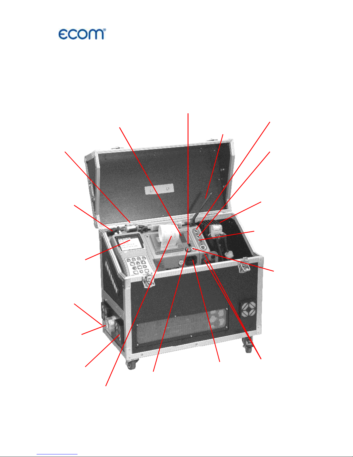
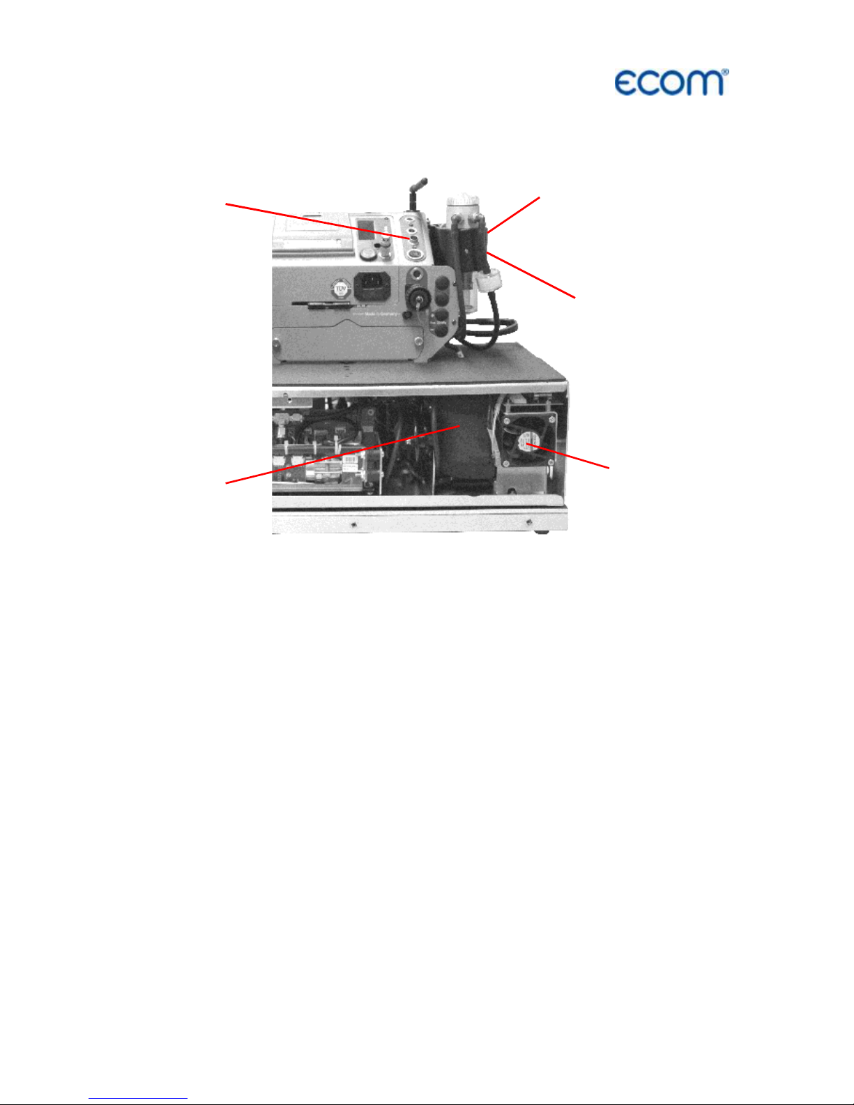
1. Instrument design
1.1. Basic module
Connection mains
power plug
with fuse
(630 mA / 250 V)
Connection
heated probe
PTFE
filter 2
Connection
air
temperature
Condensate trap
with gas cooler 1
and fine dust filter
Connection
gas hose
Connection
pressure
Connection
draught
Radio antenna
Cable socket
by wire transfer
basic / control modules
Integral
printer
PTFE
filter 1
Control
module
(see next page)
Info display
(see chapter Control)
Basic
ON / OFF
Converter
cartridge
Fresh
air 1
Fresh
air 2
Page 7
ecom-
J2KN
pro
TECH
Page 7
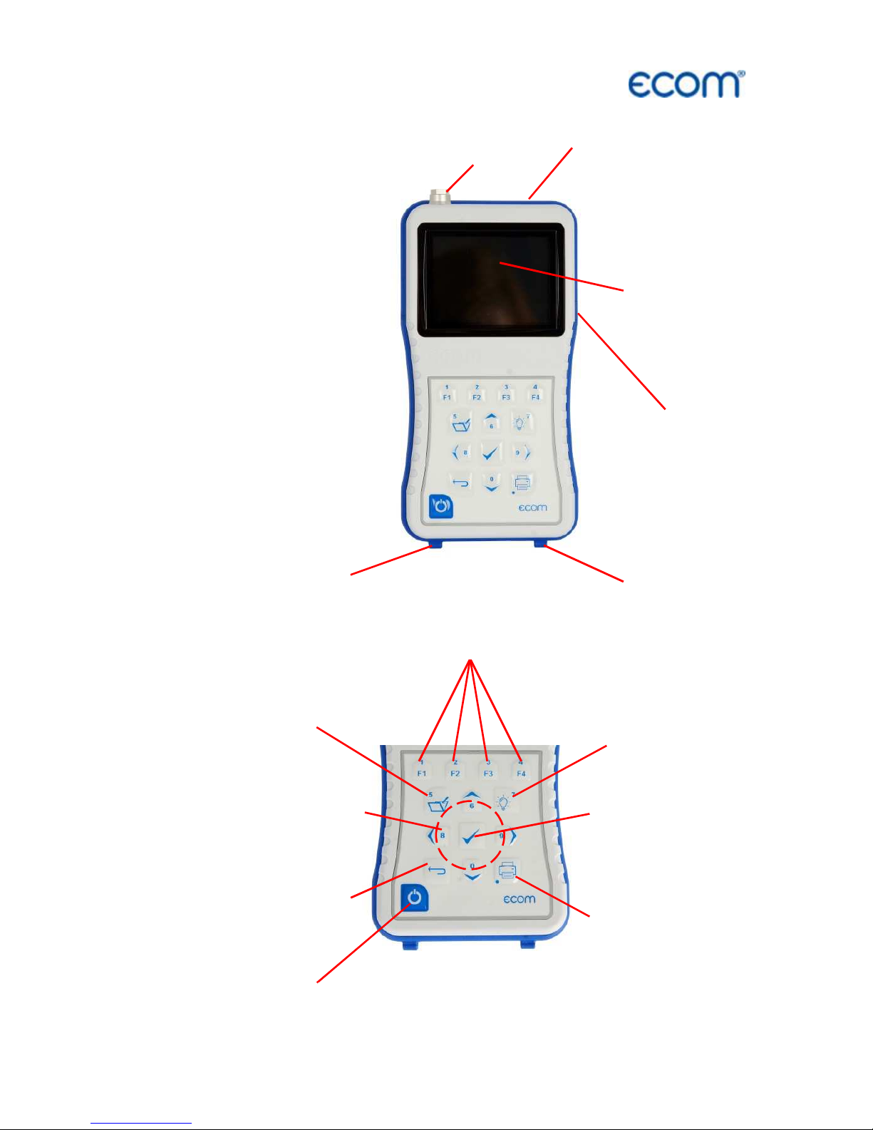
1.2. Control module
Slot for Multi-
Media-Card
Graphics
Display
Connection
USB
Connection
keyboard
Connection air
temperature
Socket for connection
cable by wire
transfer basic
ESC key
(quit/
escape menu)
In the input mode,
the keys are used
for numerical in-
puts
OK key
(confirm
selection)
Cursor keys
(Up/Down/Right/
Left/Scroll)
Measurement
values recording
Print key
(access to print-
ing menu)
Switch ON/OFF
control module
Display back-
lit ON/OFF
Function keys
(function shown on display)
Page 8
Page 8
ecom-
J2KN
pro
TECH
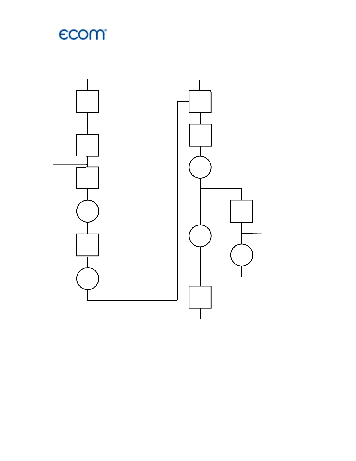
2. Gas flow scheme
Sample gas outlet
(TOXIC GAS)
Gas cooler 1
(with filter and
safty filter)
Heated filter
Heated hose
Electrochemical
sensors
PTFE Filter 1
NDIR Standard
Gas cooler 2
PTFE filter 2
NDIR Advanced
PAS/
UV
CLD
Converter
Gas pump 1
Gas pump 2
Fresh air 2
Fresh air 1
Flue gas duct
Ozon
Page 9
ecom-
J2KN
pro
TECH
Page 9
3. 2-stage Peltier cooler
Flue gas with a temperature above the dew point is sucked spiral via
a long gas path thru a surface coated metal body with good thermal
conductivity. The gas radiates its heat to this metal body
A Peltier
element (semiconductor cooling element) flown by a continuous
current is thermally connected with this body and with a second
metal body with cooling ribs and ventilation slots. The current thru
the Peltier element creates a heat transfer from hot to cold, drains
the heat of the metal body flown by gas and transfers it to the outer
cooling body. This heat is transferred thru ventilation to the
surrounding air.
The condensation issued by the heat loss of the gas drops in a
receptacle and is pumped out by a permanent working hose pump.
The sucking capacity of the gas conveying pump avoids a sufficient
dwell time of the gas with the condensate, so that wash out reactions
(NO
2+H2
O > H2NO3) do not take place. At the cooler outlet the gas
has a temperature of ca. 5 °C with a relative saturation of nearly 100
% relative humidity (corresponds to a water steam content < 7 g/ m
3
).
Fan 1
Gas
cooler 1
Gas
inlet
Gas
cooler 2
Fan 2
Page 10
Page 10
ecom-
J2KN
pro
TECH
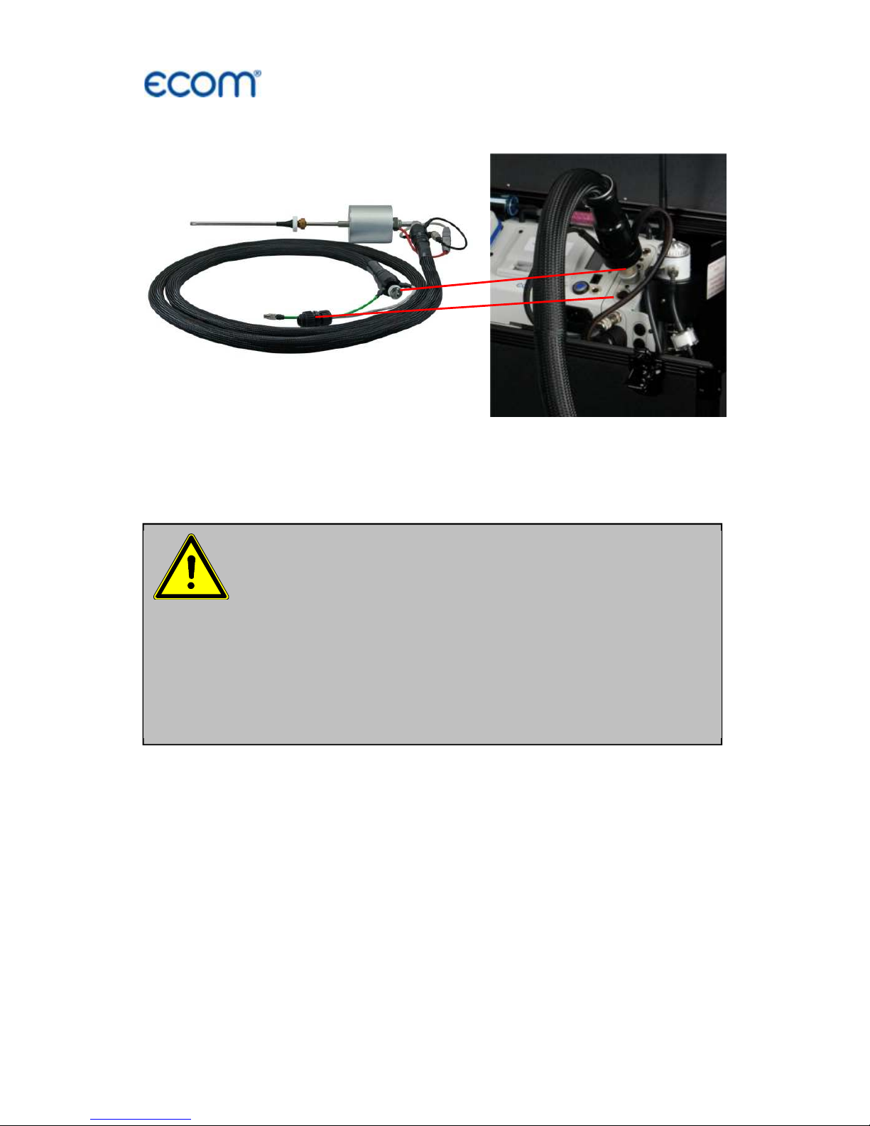
4. Heated sampling system
By using a heated sampling system (option) is possible to measure
water-soluble substances (NO
2
and SO2) without washout. A built-in
hot gas filter protects the instrument especially for long-term
measurements from fouling. The maximum exhaust gas temperature
when using the heated sampling system is 500 ° C.
Please note:
- Do not bend the tube
- Heated tube has to be cooled out after the
measurement
- Heated tube may not be folded too tight
(use the whole under case)
- Do not put the heated tube in water
- Clean or replace PTFE filter regularly
Direct connection at the front
of the J2KNpro TECH
Heated sampling system
Page 11
ecom-
J2KN
pro
TECH
Page 11
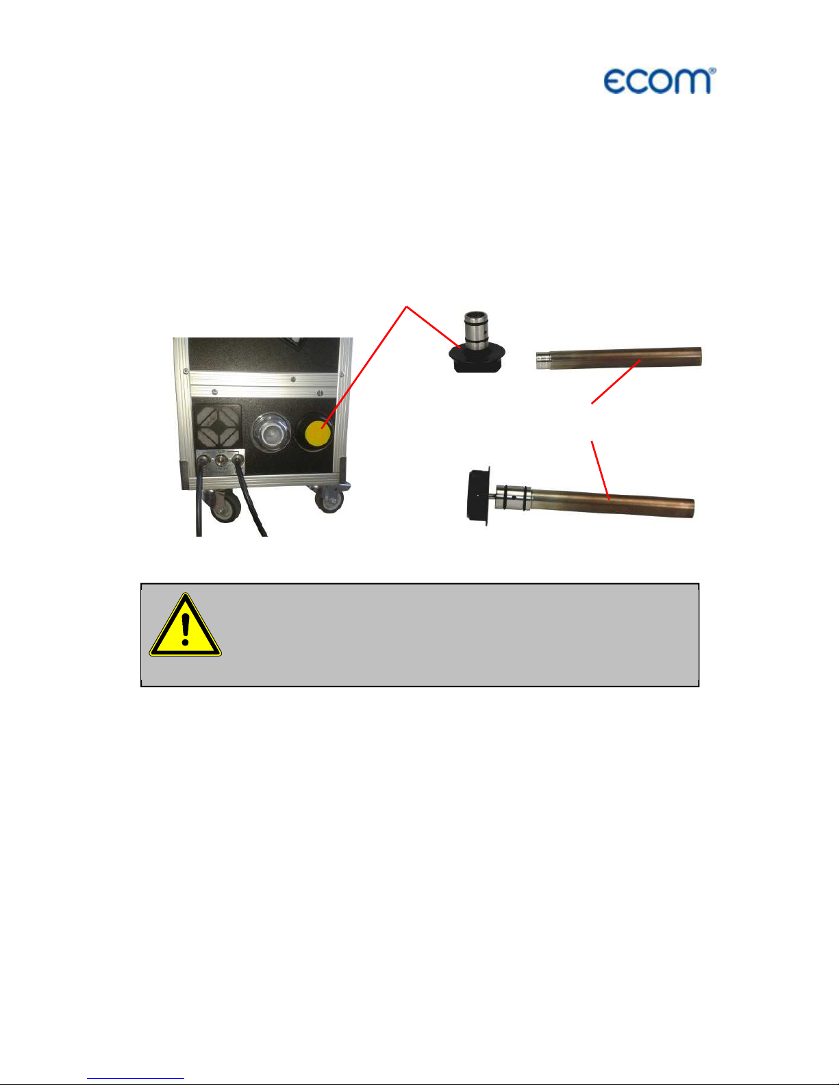
5. Converter (option)
The NO2 / NO Converter converts catalytically the NO2 content of
the sample gas into NO. For this purpose, the sample gas is passed
through a converter cartridge from stainless steel having a catalyst
filling. This conversion allows an indirect measurement of NO2
(switch function key <F1> at the control unit to toggle between NO
and NOx measurement).
Replace reactor cartridge
:
Replace the reactor cartridge if the conversion rate from NO2 => NO
falls below the required value. Changing the reactor cartridge is
possible without tools in a very short time. We recommend turning off
the instrument and letting cool down for approximately 1 hour before
changing the cartridge. This minimizes the hazard of burning. There
is also the possibility of changing cartridges in a heated instrument,
but the converter cartridge has a temperature of about 200 ° C.
The converter cartridge is hot! Touching may cause
severe burns! Wear suitable protective gloves and
protect the converter cartridge against access!
Reactor fastener
Reactor cartridge
Page 12

Page 12
ecom-
J2KN
pro
TECH
How to change the reactor cartridge:
- Stop sample gas flow (deactivate NOx measurement).
- Before opening the reactor fastener make sure that no toxic or
dangerous gases or components are provided within the gas way.
(Purge the tubes with inert gas or air).
- Turn the reactor fastener counter anticlockwise up to the end of the
thread.
- Pull out the fastener with the reactor cartridge carefully.
- Let the cartridge cool down if needed.
- Pull the reactor cartridge out carefully from the reactor fastener
(wear protective gloves).
- Replace new reactor cartridge to the reactor fastener.
- Push the cartridge carefully to the reactor opening and turn the
reactor fastener clockwise up to the end of the thread.
Use only spare parts and
consumables from ecom!
Page 13
ecom-
J2KN
pro
TECH
Page 13
6. Power supply
The basic module of the ecom-J2KN
pro
TECH is delivered with
internal loading unit. The connection of the power plug is needed to
operate the instrument.
The control module of ecom-J2KN
pro
TECH is powered by 3 nickelmetal-hydride accumulators (type AA). In case of need, the
accumulators can be recharged by docking the control module to the
basic module.
Used accumulators can be returned to us or brought
to recycling stations of public waste disposal compa-
nies respectively accumulators selling stores!
Never use batteries, to operate the control
module of the ecom-J2KN
pro
TECH!
Page 14

Page 14
ecom-
J2KN
pro
TECH
7. Radio communication basic / control module
Thanks to the detachable control
module the basic module can be
monitored wireless. The basic module
can be unlocked as follows:
1. Press to unlock.
2. Tip control module forwards
3. Release control module from basic
module
The information exchange between
control and basic module is performed
via radio transmission (868 MHz) with
coverage of approx. 70 m (by free
sight). The quality of the radio
transmission is documented by a bar
indication in the main menu of the
instrument (long bar = good radio
communication).
By interruption of the radio
communication, an error message is
displayed. By persisting disturbances of
the radio communication, a cable
(option) can take over the transfer
(connection betwen socket DATA on
control unit and socket DATA on basic
module).
If the basic module is switched off and
the control module not, so the display
will show an error message inviting to
fix the control module in its docking
station (helps also not to forget the
control module). Observe this order, quit
with <ESC> and finally switch off the
control module.
Gas
analysis
Pressure
Soot..Oil trace
Data processing
Adjustments
Control
Diagnostics
Unlocking
Bar indication
radio quality
-- ECOM-J2KN --
Radio connection
interrupted!
Use cable or
switch on basic
module!
Quit
with:
-- ECOM-J2KN --
Place J2KN in
basic mod.!
Quit with:
Page 15
ecom-
J2KN
pro
TECH
Page 15
8. Data record
The multi-media card enables the storage of both punctual
measurements and data logger records.
The values of punctual measurements are written in a text file
(J2KDV.txt). Those of data logger records in a csv file (J2KDL-xx.csv
/ xx = records numbered consecutively).
Both file types have the same structure and can be imported
respectively opened in Excel. See chapter „Technical Data“ for data
format information. The files can be transferred on the PC using a
card reader. The following conditions must be fulfilled for using a
multimedia card:
- ecom-J2KN
pro
TECH
- min. card volume 32 MB - max.32 GB (UHC)
- card formatted on 16 bit FAT or FAT32
- SD cards from SanDisk recommended
- PC with card reader
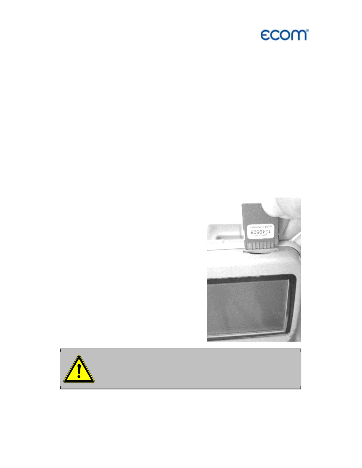
Insert the multi-media card as shown.
Take care that the card does not stand
out and hooks on.
Never pull out cards during data record
- data loss
and damaging of the data carrier possible!
Page 16
Page 16
ecom-
J2KN
pro
TECH
9. Starting
Once the control module has been switched on (key <I/0>), the main
menu is displayed.
8 sub-menus with the following functions are displayed (non-visible
sub-menus can be called up scrolling the arrow keys):
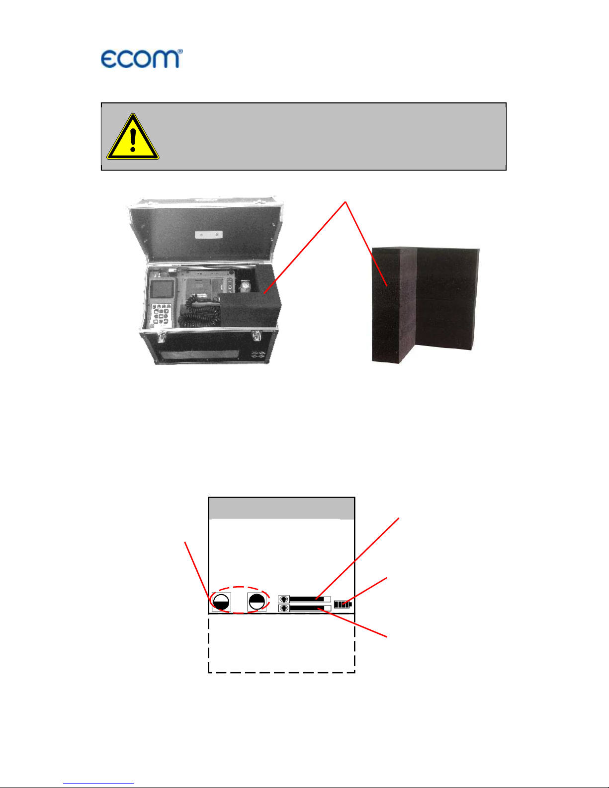
Before starting up please remove
the transport protection!
Transport protection
Gas analysis
Mean value
Pressure
Soot..Oil trace
Data processing
Adjustments
Control
Diagnostics
Bar indication
radio quality
Bar indication
transfer quality
Battery voltage
(charging status)
Display con-
trast adjusta-
ble with
F1 and F2
Page 17
ecom-
J2KN
pro
TECH
Page 17
- Gas analysis : Perform gas analysis
- Mean value : Measurement with mean value calculation
- Pressure : Perform draught or pressure measurement
- Soot...Oil trace : Input of soot measurements results
- Data processing : Assign measurements / Load or send data
- Adjustments : Modify instrument adjustments
- Control : Check operation state of instrument
- Diagnosis : Read-out of firing automats
(only in connection with ecom-AK) /
dT-measurement
If measurements are carried out first the basic module has to be
turned on (switch below the info display). Select the sub-menu "Gas
analysis" with the cursor keys and confirm with <OK>. The
instrument starts with a warm-up phase (max. 30 min.). After the
sensors are at operating temperature, a 15-minute stabilization
phase follows followed by a 3-minute calibration with fresh air.
Simultaneously, the message appears asking if you want to use the
data processing. If you want to assign the sampled data to a specific
plant, so press <F1> (<F4> = no: measurement will be performed
without assignment).
Fuel types acc. to 1
st
BImSchV*:
Fuel oil (B)
Natural gas (B)
City gas (B)
Coke oven gas (B)
Liquid gas (B)
Use the cursor keys to select the
desired fuel type and confirm with
<OK>.
* Country specific fuel types programmable on demand.
Make sure that the instrument is turned on in
clean air, because the zero point of the sensors
will be updated with fresh air!
Fuel type
Fuel oil (B)
CO2max
A1 B
15.4
0.50
0.007
Select:
Do you wish to
use the data
processing?
YES Quit with
! NO
Page 18
Page 18
ecom-
J2KN
pro
TECH
Input number
25.11.2017
Please use the
numeral keys!
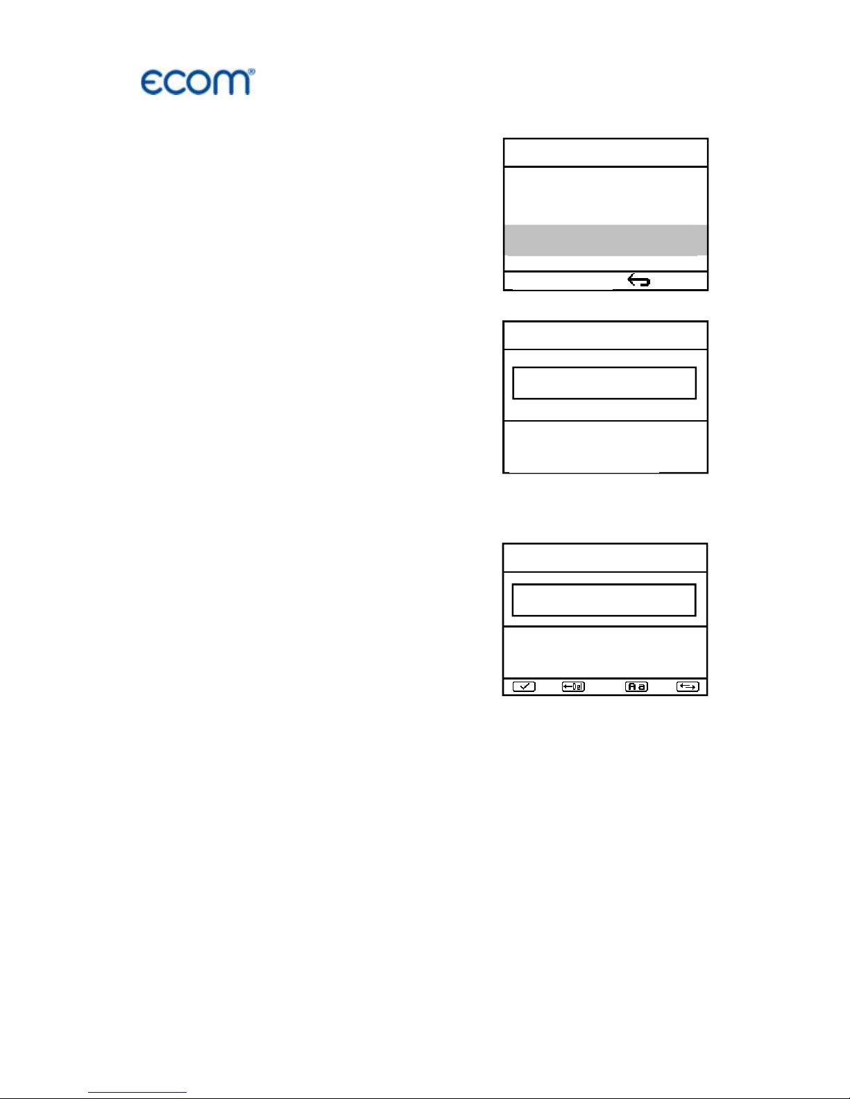
10. Input or select plant specific data
To call up plant data recorded in the
ecom-J2KN
pro
or to create a new file,
the following possibilities are available:
Create new (is automatically selected
by first use of a MM card): To create a
new file, a numerical number can be
assigned.
-Select „Create new“
-Confirm with <OK>.
-Input a number (max. 16 numbers):
Example: "25.11.2017"
Tip: We suggest a date-related input to easily find the data record
later on via the search function (search per date).
After confirming with <OK> it is possible
to enter a text (max. 6 lines with 20
indications) with a software keyboard
(for print out or data processing).
Proceed as follows:
-choose Text line 1 with the cursor keys
<up/down> and confirm with <OK>
-select keyboard (4 keyboards are available) with <F3>
-select with the cursor keys <up/down/right/left> a character
(selected character is black deposited)
-choose the character with <OK> (the last character can be deleted
by pressing <F2>)
-repeat procedure, until line is complete
-if you want to correct a character, proceed as follows:
-interrupt choosing characters with <F4>
-select character with the cursor keys <right/left>
-activate choosing characters with <F4> and set a new character
-select the next line after pressing <F1>
You can close the text input with <ESC>. Activate the next free record number with <OK> and start flue gas measurement with <F1>.
Insert Text
25.11
A B C D E F G H I J K L M
N O P Q R S T U V W X Y Z
Ä Ö Ü .
- ( ) [ ] { }
Selection upon:
Search word
Memory number
Create new
Quit with:
Page 19

ecom-
J2KN
pro
TECH
Page 19
Record number: For check of the plant
already stored in the instrument, the
selection upon record number is most
appropriate.
- Select „Record number“
- Confirm with <OK>.
- Input a random record number:
Example: "1" for record number 1
- Press <OK> once the input is completed to call up said data
record number. The cursor keys <Up/Down> enable the check of
the record numbers.
- Press <F1> to select the first record number and <F2> for the last.
- Press <F4> to delete the content of the selected record number.
- Press <OK> to activate the record number.
- Finally press <F1> to start the gas analysis.
Memory number
1
Please use the
numeral keys!
Selection upon:
Search word
Memory number
Create new
Quit with:
Page 20

Page 20
ecom-
J2KN
pro
TECH
Search word: If the plant code is known, it is possible to find the
plant data stored with help of a search machine.
-Select "Search word" and press <OK>.
-Input with software keyboard 4 related
figures of the plant code:
Example: "25.11"
for plant code 25.11.2017
-Press <F1> after input to start the
searching process. All possible
correspondences with these figures
sequence will be filtered. The selection
can be stepped thru with the arrow keys
(<F1> for selection beginning, <F2> for
selection end)
-Press <OK> to activate once the desired
data block is found
-Press / „View“ / <OK> to view the
previous analysis at this plant
All measured and calculated values can
be called up on 4 display pages using the
arrow keys to step thru.
Press <F1> to quit the previous measurement and start recording of
the current measurement values.
Memory number 1
25.11.2007
Data record 12:15:53 25.11.17
Further pages:<↑↓> Memory number 1
Gas analysis 12:15:53 25.11.17
Further pages:<↑↓> Memory number 1
O2 3.2 %
CO2 13.1 %
CO 0 ppm
Eff. 92.5 %
Losses 7.5 %
Exc. air 1.18
T.Gas 184.4 °C
T.Air 20.3 °C
Draught -0.03 hPa
CO measurement 12:15:53 25.11.17
Further pages:<↑↓> Memory number 1
O2 17.5 %
CO 0% 738 ppm
CO 123 ppm
Lambda 7.00
O2 value in air
O2 value in air 12:15:53 25.11.17
Further pages:<↑↓> Memory number 1
O2 19.5 %
CO 3 ppm
Zug 0.01 hPa
Soot..Oil trace
Mean value
: 0.5
Boiler temp. : 65°C
1st Soot meas.: 0.5
2nd Soot meas.: 0.3
3rd Soot meas.: 0.7
Oil trace : NEIN
dT measurement
dT measurement 12:15:53 25.11.17
Further pages:<↑↓> Memory number 1
T1 70.4 °C
T2 56.3 °C
dT 14.1 °C
Measurement
available
Search word
25.11
A B C D E F G H I J K L M
N O P Q R S T U V W X Y Z
Ä Ö Ü .
- ( ) [ ] { }
Memory number 1
25.11.2017
End with : !
F1:First record
F2:Last record F4:Delete
Page 21

ecom-
J2KN
pro
TECH
Page 21
11. Flue gas analysis
11.1. Gas analysis
After warm-up and calibration phase, the instrument switches over to
the measurement mode. The gas measurement values can be
viewed on different display pages. Use the cursor keys to scroll the
pages.
With <F1> you can switch from the measured value display to a
menu or selected before (see chapter Adjustments). Possible menu
options are: Soot... Oil trace, Data processing, Adjustments, Control,
Fuel type, Standby, Purge, Eff. (C), Memory -> M, CLD NO <-> NOx,
WLAN, Pressure. Further you can switch with <F1> from any menu
back to the measured value display.
With <F2> you can print and store the measured values into the
intermediate memory at the same time.
With <F3> you can switch off the CO sensor, in order to protect the
sensor against too high concentrations (only required for
electrochemical CO sensor). The automatic disconnection will switch
off the CO sensor at approx. 2500 ppm (also for CO IR).
With <F4> you can switch from the measured value display to a
menu selected before (see chapter Adjustments). Possible menu
options are: Soot... Oil trace, Data processing, Adjustments, Control,
Fuel type, Standby, Purge, Eff. (C), Memory -> M, CLD NO <-> NOx,
To compensate a possible sensor drift, it is
important to calibrate the instrument with fresh
air at regular Intervals!
Hotkey
<F1>
Hotkey
<F4>
Store and print
measured
values <F2>
Switch off
CO-Sensor
<F3>
O2 3.2 %
CO2 13.1 %
T.Gas 184.4 °C
T.Air 20.3 °C
Gas analysis
25.11.07
Page 22

Page 22
ecom-
J2KN
pro
TECH
WLAN, Display values, Pressure. Further you can switch with <F1>
from any menu back to the measured value display.
The position of the measured and calculated values (gas analysis)
on the display pages is free selectable (choose „Display values“ for
<F4> Hotkey). For alteration of the existing succession respectively
personal listing, proceed as follows:
-Press <F4> to activate the function.
-select the line with the cursor keys <up/down>,
-select the measured or calculated value with the cursor
keys <right/left>,
-repeat this procedure until all modifications are completed.
-Press <F4> to deactivate the function.
Instruments with magnetic valve and fresh air connection
Instruments that are equipped with magnetic valve technology and
fresh air connection are able to be purged or calibrated with fresh air
without taken out the probe out of the flue gas duct:
For fresh air purging, press the <Enter> key from the measured
value display, select the menu item "Fresh air purge" and press the
<Enter> key again. The fresh air purging can be ended with <F3> in
the measured value display.
For fresh air calibration, press the <Enter> key from the measured
value display, select the menu item "Re-Calibration" and press the
<Enter> key again. After the following query has been answered
with "YES" (<F1>), the 1-minute calibration phase starts.
Core stream search
Position the sampling probe in the exhaust channel so that the
thermocouple is fully surrounded with the gas.
Page 23

ecom-
J2KN
pro
TECH
Page 23
Perform the measurement in the core stream of the exhaust gas
channel (probe placed in the highest gas temperature area).
A trend indication for T.Gas easies the core stream search. As long
as the display shows a + symbol, the measured temperature
increases, it means the probe tip moves towards the core stream. If
a - symbol is displayed, pull the probe out of the core stream and the
temperature sinks. If no temperature change is shown for at least 3
seconds, so the trend indication will be deleted.
CO
2
, efficiency, losses, excess air and dew point are calculated
values. They can only be calculated if realistic values for the basic
parameters O
2
and temperatures are available. It must be
ascertained that:
O
2
< 20,5 % and T.Gas - T.Air > + 5 °C
are given. The dew point can only be calculated accurately if, in the
menu "Adjustments", the current barometric air pressure value has
been entered. This value cannot be determined by the ecom-
J2KN
pro
. If the gas temperature falls below the dew point (between
25 and 65 °C), ETA will be calculated with condensation. In the
display (C) appears behind ETA.
Correct measurement values are displayed first after a short delay,
necessary for the gas transport and the build-up of a stable
electrochemical reaction at the sensors. This time period lasts
approx. between 1 and 1.5 minute. For recording, printout and
evaluation wait until the values do not change anymore. If deviations
higher than 2 ppm still occur by the gas values, they can be due to
unstable pressure conditions in the exhaust channel.
Core stream
search
T.Gas °C
Gas analysis
25.11.17
180.4
Zoom Display:
Adjust parameter
with Cursor keys
<right/left>
Page 24

Page 24
ecom-
J2KN
pro
TECH
If the measurement values are stable
and the results can be printed out, press
the key <Record> (disc symbol) to
transfer the values in the intermediate
memory (caution: store gas analysis
and CO measurement values
separately). The values are stored for a
later printout and, if need be, for a final
data record storage.
If a printout of the values should be made simultaneously to the
intermediate recording, so press <F2> (the complete content of the
intermediate memory will be printed).
Measurement stored in
intermediate memory
O2 3.2 %
CO2 13.1 %
T.Gas 184.4 °C
T.Air 20.3 °C
Gas analysis 25.11.17
recorded!
Page 25

ecom-
J2KN
pro
TECH
Page 25
11.2. Flow measurement (option)
This measurement can be done with a
pitot tube. At first the pitot factor of the
pitot tube must be entered
(„Adjustments“ / „Internal“ / „Pitot
factor“). After connecting the pitot tube
to the instrument, the zero point of the
sensor can be set with <F4>. With <F1>
the cross section of the flow channel
can be entered (needed for calculation
of the flow rate). After the pitot tube is
positioned in the flow channel, the
display shows the speed (m/s), the flow
rate (Nm
3
/h) and the differential
pressure (Pa). If the value indicated is
stable, press <Record> to store the
value in the intermediate memory. If a
printout of the values should occur
simultaneously to the recording in the
intermediate memory, press <F2> (the
complete content of the intermediate
memory will be printed out).
Connections for
pitot tube
Measurement stored in
intermediate memory
V.Gas
0.4 m/sec
M.Flow
44 Nm3/h
dP 0.1 Pa
Flow measurem. 25.11.17
recorded!
Flow measurement
Page 26

Page 26
ecom-
J2KN
pro
TECH
11.3. Pressure measurement (option)
A trend indication for the draught conditions in the exhaust channel
can already be determined during the gas analysis. Nevertheless the
value for the chimney draught will not be stored together with the gas
values while pressing the key <Memory>.
Indeed the difference pressure sensor tends to drifts because of its
sensibility and, for an exact measurement it is consequently advised
to re-calibrate the sensor immediately before sampling and
documenting the value.
Access the menu while selecting the
sub-menu "Pressure". The current
value is displayed as well as the
instruction to adjust the zero point of the
sensor. Release hereto the draught
hose from the instrument for a short
moment and press <F4>. The sensor is
herewith re-calibrated.
Fix the draught hose again. The display
shows the exact measurement value
which can be stored while pressing
<Memory> and added to the previous
results in the intermediate memory. The
stored value is shown on the display.
Press <ESC> to quit the differential
pressure measurement menu.
For this option a
probe
type SB is required!
Pressure
-
0.12
hPa
--.-- hPa
New 0
point
Pressure
-
0.12
hPa
-
0.12 hPa
New 0
point
Measurement stored in
intermediate memory
Page 27

ecom-
J2KN
pro
TECH
Page 27
11.4. Soot...Oil trace (option)
The sub-menu "Soot...Oil trace"
enables the input of measured results
for boiler temperature, soot dots and oil
trace. Select the line „Boiler temp.“
and press <OK> to activate the input.
The input can be made using the
numerical keys. Press <OK> to store
the value in the data record of the
measurement.
The soot dot measurement is to be performed with the optional
heated pistol grip probe which heating function prevents the filter
paper to become wet because of the humidity issued by the
combustion condensate. The filter paper slot is hereby heated up to
approx. 70 °C. Switch hereto the probe heating of the pistol grip
probe while selecting „Adjustments / Internal / Probe heating /
<F1>“.
Proceed as follows:
-Switch on the probe heating while selecting „Adjustments / Probe
heating / <F1>“.
-Insert a filter paper in the paper slot.
-Select the line „1st. Soot meas.“.
-Press <OK> to start the measurement. The display shows the
volume to be sucked and the pump starts sampling.
If the soot dot analysis are made with a manual pump the sucking
procedure can be interrupted while pressing <F4> (result value can
immediately be entered).
Once 1,63 litres has been sucked in, the instrument will instruct to
input the opacity degree. Proceed as follows:
-Release the filter paper from the probe slot.
For this option a
probe
type SB is required!
Soot..Oil trace
Mean value
:
-.- Boiler temp.: 66°C
1st Soot meas.: -.2nd Soot meas.: -.3rd Soot meas.: -.Oil trace : ----
Page 28

Page 28
ecom-
J2KN
pro
TECH
-Compare the greyness with the opacity scale.
-Input the result using the numerical keys and press <OK>.
-Repeat this procedure until all 3 soot dot analyses are completed.
The mean value will be calculated and automatically stored.
The result of the oil trace check is to be documented as follows:
-Set the cursor on the line "Oil trace".
-Input the result with <OK>
("NO", "YES" or "- - - ")
-Press <ESC> to quit the menu once all necessitated inputs have
been entered. The measurement is now completed.
Get the probe cooled down before putting
it back in its fixation!
Soot..Oil trace
Mean value
:
1.0 Boiler temp.: 66°C
1st Soot meas.: 1.0
2nd Soot meas.: 0.5
3rd Soot meas.: 1.5
Oil trace : NO
Page 29

ecom-
J2KN
pro
TECH
Page 29
11.5. Measurement record and printout
Press <Print> (printer symbol) to enter
the printing menu. The sampled data
can be checked one more time („View
memory“, <OK> and scroll with the
cursor keys).
The software keyboard enables the
input or correction of the 6 x 20character text. Select hereto „Input
text“, press <OK> and input text (see
page 13).
Press „Memory -> M“ and <OK> to
store the all data -if correct- in the
internal memory or on the multi-media
card. Once the transfer is completed, a
"Memory symbol" appears on the
bottom right of the display. The entered
text will only be recorded in the data
record by use of the multi-media card.
Select „Start printout“ and press
<OK>) to start a printout.
Press <ESC> to turn back to the gas
analysis menu.
Once the gas analysis is completed, transfer the va
l-
ues recorded in the intermediate memory to the
Multi-Media-Card otherwise they could get
lost by switch-off of the instrument!
Memory symbol
Start printout
View memory
Memory -> M
Insert Text
--
ECOM
-
J2KN
--
Quit with:
Start printout
View memory
Memory -> M
Insert Text
--
ECOM
-
J2KN
--
Quit with:
Start printout
View memory
Memory -> M
Insert Text
--
ECOM
-
J2KN
--
Quit with:
Start printout
View memory
Memory -> M
Insert Text
--
ECOM
-
J2KN
--
Quit with:
Page 30

Page 30
ecom-
J2KN
pro
TECH
11.6. Mean value measurement
By mean value measurement function measurements can be taken
in an adjustable time frame and mean values can be calculated.
Should the several measurement values or the mean value result be
stored a storage place has to be selected as described in chapter 7.
If the function “Store” is activated, based on this storage place all
measurements will be written consecutively on the next storage
places. If the function “Store” is not activated, the mean value result
can be stored on MMC with <Print> / „Memory -> M.
After run through fresh air calibration
the menu point “Mean value” can be
chosen. Before the mean value
measurement can be started the
settings for “Meas.time”, “Scanning”,
“Printer” and “Storage” should be
checked and if necessary be changed.
The meanings are:
-Meas. time = Time frame in which the
mean values will be calculated
-Scanning = time between the
measurements taken for mean value
calculation
-Printer = logging of measurements
taken for mean value calculation
-Store = all measurements for mean
value calculations will be stored
“Measurement time” and “Scanning” can be adjusted as follows:
-select menu point and confirm with <OK>
-with the numeric keys set the desired time:
0.01 = 1 sec. = minimum value
59.59 = 59 min and 59 sec. = maximum value
-confirm with <OK>
Gas analysis
Mean value
Pressure
Soot..Oil trace
Data processing
Adjustments
Control
Diagnostics
Start measurement
Meas. time
Scanning
Printer
Store
Mean value
Quit with:
Page 31

ecom-
J2KN
pro
TECH
Page 31
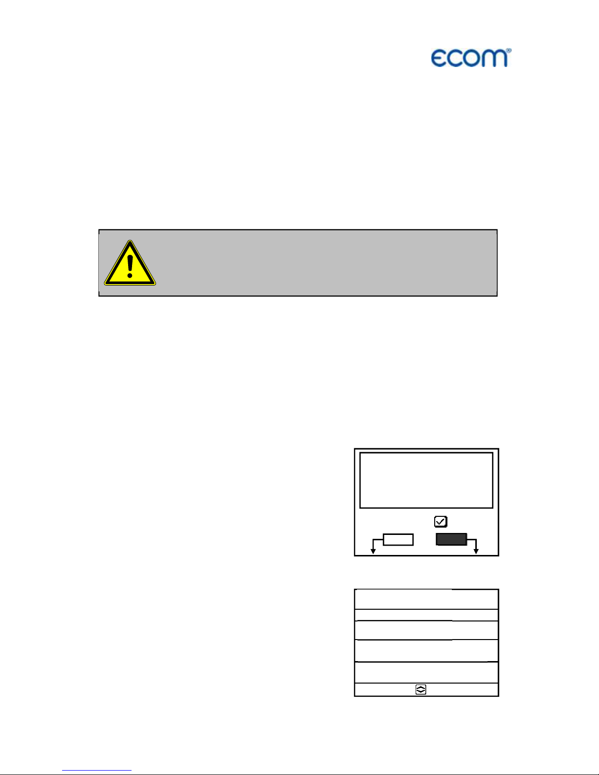
The setting for “Printer” can be changed as follows:
-select menu point and confirm with <OK>
-select desired setting with the curser keys
-confirm with <OK>
The setting for “Store” can be changed as follows:
select menu point and confirm with <OK>
activate storage function with <F1>
deactivate storage function with <F4>
By ‘Start measurement’ / <OK> the
evaluation of the measurement values
will be started. On the display the actual
mean values will be shown (will be
updated with new measurement values
/ switch to the actual values with cursor
keys <up/down>). It is possible to scroll
through the values with the cursor keys
<right/left>. With <F2> you can
interrupt and with <F4> stop the
measurement.
After finishing the measurement time a protocol of the results with all
mean values can be printed (key <Print>).
O2 3.2 %
CO2 13.1 %
CO 0 ppm
Eff. 92.5 %
Losses 7.5 %
Exc. air 1.18
T.Gas 184.4 °C
T.Air 20.3 °C
Mean value 25.11.17
15:59 min
Page 32

Page 32
ecom-
J2KN
pro
TECH
11.7. After measurement
Fold radio antenna before
closing the case!
Get the heated sampling system cooled down
before putting it back in its case!
Radio antenna
Heated sampling
system
Please place transport protection
before transport!
Transport protection
Page 33

ecom-
J2KN
pro
TECH
Page 33
12. Adjustments
Additionally to the ecom-J2KN
pro
TECH
functions described previously, various
adjustments can be made in the
instrument.
From the main menu select the submenu "Adjustments" and confirm with
<OK>. A selection of modifiable
parameters, adjustable according to the
application, is displayed.
Place the cursor on the desired line and
press <OK> to call up or modify the
adjustment.
The modifiable parameters are:
Calibr. sensors:
-Select calibration menu ("Calibr. sensors" <OK>)
-Choose sensor with cursor keys and confirm with <OK>
-CO / NO / NO2 / SO2 etc. calibration
(Important: Span gas must get pressure-free to the instrument!)
-Flow with span gas
-Wait for stabilisation of value
-By drift press <OK>
-Set correct value with number keys
-Confirm input with <OK>
-T. Gas / T. Air calibration
-Create reference temperature
-By drift press <OK>
-Set correct value with number keys
-Confirm input with <OK>
-Pressure calibration
-Set draught sensor on 0 with <F4> key
-Create reference pressure
-By drift press <OK>
-Set correct value with number keys
-Confirm input with <OK>
Calibr. sensors
Re-Calibration
Unit
Second unit
Ref. O2
Fuel type
Set clock
Paper feed
Internal
Tightness test
Quit with:
Page 34

Page 34
ecom-
J2KN
pro
TECH
-Soot measurement calibration
-Connect suitable reference principle for volume determination
-Insert filter paper
-Confirm with <OK>
-Start soot measurement with <OK>
-After 1,63 l volume has been sucked, press again <OK>
(operation time of the pump will be memorised)
-Press <ESC> to return to the main menu
Unit (adjustment with cursor keys):
-Calculation of gas concentrations in:
-ppm = volume concentration (parts per million)
-mg/m
3
= mass concentration per volume unit
-mg/kWh (undiluted) = mass concentration per power unit
-mg/MJ (undiluted) = mass concentration per power unit
-ppm (undiluted) = volume concentration (parts per million)
-mg/m
3
(undiluted) = mass concentration per volume unit
Undiluted:
-Conversion of the gas concentration on selected reference oxygen:
-mg/kWh and mg/MJ are always calculated on 0% O2 basis
-Conversion formula:
E
ref
= E
meas
*
21 - O
2ref
21 - O
2meas
Page 35

ecom-
J2KN
pro
TECH
Page 35
Second unit (adjustment with cursor keys):
-two different unit for one gas concentration possible
Ref. O
2
(for ppm and mg/m
3
units - Input after <OK> pressing):
-Input of O
2
reference value O
2ref
Fuel type (press <OK> to access selection list):
-Modification of adjusted fuel type (e.g. by measurements at
combination plants)
Set clock (press <OK> to access setting menu):
-Correction of internal clock with cursor keys
Paper feed (press <OK> to activate paper feeding):
-Paper feed line by line
Tightness test (Start with <OK>):
-Leakage test of gas system of the
ecom-J2KN
pro
TECH
-Lock probe with a plug and start
test with <OK>
Internal (press <OK> to open menu):
-Further instrument settings:
Printout contrast (0..9)
(press <OK> to access input menu):
-Printer contrast adjustment
Recharging function
(<F1> for ON / <F4> for OFF):
-Recommended setting = OFF
Key beep (<F1> for ON / <F4> for OFF):
-Acoustical signal by key pressing
Print contraste
Reload function
Key beep
Graphic menu
Probe heating
Low power mode
Language: English
F1 Hotkey
F4 Hotkey
Eff.(C)
RF-connect. only
USB
Bluetooth
WLAN
Pitot factor
Printout
Quit with:
Page 36

Page 36
ecom-
J2KN
pro
TECH
Graphic menu (<F1> for ON / <F4> for OFF):
-Activation of graphic mode
Low power mode (<F1> for ON / <F4> for OFF):
-Switching on / off the probe heating and the gas cooler at battery
operation
Probe heating (<F1> for ON / <F4> for OFF):
-ON/OFF switch for probe heating for soot measurement
Language: English
-Info about language (3 languages selectable)
F1 Hotkey (Choose after pressing <OK>):
-Change the menu you get to after pressing <F1> in measured value
display
F4 Hotkey (Choose after pressing <OK>):
-Change the menu you get to after pressing <F4> in measured value
display
Eff.(C) (<F1> for ON / <F4> for OFF):
-ON/OFF switch for calculation of efficiency with and without
condensation
RF-connect. only (Choose after pressing <OK>):
-Standard: no radio connection if control module is located
in basic module
-RF-connect. only: radio connection also if control module is
located in basic module
-Remote: without function
USB (selection after pressing <OK>):
-Adjustment of transfer speed (Cursor keys <Up/Down>) and
Protocol (Cursor keys <Right/Left>) for the USB interface
(connection USB):
-Protocol DAS = Protocol for the program DASNT
-Protocol Enhanced = Protocol for the program DAS5
Page 37

ecom-
J2KN
pro
TECH
Page 37
Bluetooth (selection after pressing <OK>):
-Adjustment of protocol for the Bluetooth interface with the cursor
keys <Right/Left>:
-Protocol DAS = Protocol for the program DASNT
-Protocol DAS (DELAY) = Protocol for giant display with
adjustable (Cursor keys <Up/Down>) delay (0 = low / 9 = high /
adjust to a value that shows a stable indication at the giant
display)
-Protocol Enhanced = Protocol for the program DAS5
WLAN (selection after pressing <OK>)
Instrument as Access Point (for connection with mobile terminals):
-(Start/Stop WLAN: manual switching of WLAN connection
– available only with deactivated Auto Connect)
-Access Point: (<F1> for ON / <F4> for OFF)
-(W.O.) Auto Connect: Automatically connection
(<F1> for ON / <F4> for OFF)
-Security: use password for connection
(<F1> for ON / <F4> for OFF)
the password is „1234567890“
-Channel: Input channel (1 – 13)
(selection after pressing <OK>)
Connection with existing network:
-(Start/Stop WLAN: manual switching of WLAN connection
– available only with deactivated Auto Connect)
-Existing Network: available only with deactivated Access Point
-(W.O.) Auto Connect: Automatically connection
(<F1> for ON / <F4> for OFF)
-Network scan: Search for available networks
(selection with <OK>)
-WPA password: Input of password for selected network
With first use of the Bluetooth connection to PC type
in the shown password!
Page 38

Page 38
ecom-
J2KN
pro
TECH
Pitot factor (selection after pressing <OK>):
-Input of pitot factor for flow rate calculation (ecom flow probe =
0.93). If the flow rate calculation is not needed, set pitot factor to 0
Printout (selection after pressing <OK>):
- Text input for printout on measurement protocol (8 x 24 characters)
- Input the text of line 1 as follows:
1. Activate character selection list with <OK>.
2. Select keyboard type with <F3>
(4 different keyboards available).
3. Use the cursor keys to select the desired character
(selected character is outlined by black background).
4. Confirm selection while pressing < OK >.
5. Repeat procedure until desired text is complete.
6. Once input for line 1 is completed, deactivate the characters
selection mode with <F1> and move to the second line with the
cursor key <Down>.
7. Once all lines have been processed as desired, exit the menu
with <ESC>.
Page 39

ecom-
J2KN
pro
TECH
Page 39
13. Control
The sensors alter their output values along the operation period. The
programme controls the sensors and corrects drifts. If the drifts and
the correlated measurement errors increase, an error message is
displayed. In this case the corresponding sensor must be changed
by an authorised service centre. The control menu informs about the
current status values for the sensors as well as about (page 2 and 3
with cursor keys <up/down>):
ecom GmbH O2 10744 mV
Am Großen Teich 2
CO 7 mV
58640 Iserlohn Batt 4.50 V
--------------------- Bat.B 6.09 V
Tel.: 02371-945-5
Fax : 02371-40305
eMail : info@ecom.de
Operation hours : 8.45 hrs
Serial no. : J2KN 12345
Service tel. : 02371-945-5
Programm version : V3.0 / 12.07.16
Next unit check : 20.04.17
Control
Next service
centre
Serial number
Software
version
Radio quality
Sent frames
(radio)
Received
frames (radio)
Number of
frames (USB)
Accu voltage
control module
basic module
Operation
hours
Recommended
maintenance
date
Number of CO-
switch
-
offs
ppm hours of
CO sensor
Number of
errors
Number of
instrument
switch
-
ons
Date of last service
O2 10744 mV
CO 7 mV
Batt 4.50 V
Bat.B 6.09 V
Operation hours : 8.45 hrs
Serial no. : J2KN 12345
Service tel. : 02371-945-5
Programm version : V3.0 / 12.07.10
Next unit check : 20.04.17
Control
20
4.2 /s
4.2 /s
0.0 /s
1 X
22 ppm
4 X
11 X
O2 10744 mV
CO 7 mV
Batt 4.50 V
Control
Last service (history)
19.12.16 133 hrs
--.--.--
2.24
ltr /
min
Gas pump is running
Air valve is open
CO purging is running
Gas cooler ready for use
Heated hose ready for use
Sensors ready for use
Heated head ready for use
Gas flow
(liter per minute)
Radio mode
Calibration phase
Mains operation
(Battery operation
not possible)
Page 40

Page 40
ecom-
J2KN
pro
TECH
14. Data Processing
14.1. Communication
If a MM card is inserted in the slot, so it
will be used as record medium. The
menu „Data processing“ offers the
following functions:
Select:
For search or creation of plants files for measurement values
assignment (compare chapter “Input or selection of combustion
plants”).
View:
Recorded values to a selected plant can be viewed
(compare chapter “Input or selection of combustion plants”).
Memory (M):
Here all stored measurements (sorted
by record number) can be seen.
Individual measurement values can be
called as follows:
-Choose record number with the cursor
keys and confirm with <OK>
-Scroll with the cursor keys
-Leave record number with <ESC>
DRT <-> PC !:
Load data:
Enables the data import with USB cable
from e.g. ecom software “miniDV”
(available on our website
„www.ecom.de“). See chapter
„Technical Data“ for data format
information (please observe the transfer
options of your software!).
Select
View
Memory (M)
DRT <-> PC !
Format
Automatic measu.
Quit with:
DRT <
-
> PC !
Send dada
Load data
Quit with:
Date Time Fuel type
1 01.09.17 11:01:24 Fuel oil
2 01.09.17 11:02:34 Fuel oil
3 01.09.17 11:04:20 Fuel oil
4 01.09.17 11:07:44 Fuel oil
5 01.09.17 11:11:25 Fuel oil
6 01.09.17 11:23:02 Fuel oil
7 01.09.17 11:44:09 Fuel oil
8 01.09.17 11:53:13 Fuel oil
9 01.09.17 11:59:59 Fuel oil
10 01.09.17 11:59:59 Fuel oil
Select:
Page 41

ecom-
J2KN
pro
TECH
Page 41
Proceed as follows:
-Connect ecom-J2KN
pro
TECH and PC via USB cable.
-Select “Load data“ and confirm with <OK>.
-Answer the displayed question with YES (<F1>).
-Decide if the data recorded can be cancelled
(<F1> for YES / <F4> for NO).
-Start the data transfer on your PC.
Send data:
With this function the data records completed with measurement
values can be transferred to the PC programme (procedure similar to
chapter „Load data“).
Format:
This function is usually needed by the initial adjustment of the
instrument at our factory (preparation of internal memory for data
record).
Caution: All stored values will be cancelled!
14.2. Automatic measurement
The configuration of the ecom-J2KN
pro
TECH with operation
securing, self-regulating additional components like the condense
trap, the gas cooler and the magnetic valve technique permits even a
long term operation of the instrument. By setting time intervals for the
measurement the instrument switches autonomously to fresh air
purge after the measurement phase (gas will be sucked via the
connection fresh air) and operates a calibration phase for the
sensors.
This cycle repeats itself until the
automatic measurement will be finished.
For setting the time intervals select from
the menu “Data processing” the menu
item “Automatic measu.”. The time
intervals have following meanings:
Automatic measu.
Automatic
Data logger
Automatic time
120 min
Measurem.
time 115 min
Save to MMC 1 sek
CSV+Header
Quit
with:
Page 42

Page 42
ecom-
J2KN
pro
TECH
Automatic time (min. 10 minutes / max. 120 minutes)
Time interval from one calibration phase to the next one.
Measurement time (max. Automatic time minus 5 minutes)
Time interval within the automatic time in which the instrument
gather measurement values, i.e. in which the measurement gas will
be sucked. The difference between the measurement time and the
automatic time is used for purging the sensors with fresh air.
Save to MMC (min. 1 second / max. 255 seconds)
Adjustment of the interval time for data logger recordings.
CSV+Header (<F1> for ON / <F4> for OFF)
Adjustment of data logging with or without column headings.
Start the automatic measurement by setting the cursor to line
“Automatic” and pressing the key <OK> (on top right on the display
appears “A” for automatic).
14.3. Data logger
Here a Data logger record (“Data logger” and key <OK> / on top
right on the display appears the disk symbol) can be started or
finished (just available when using the multi-media card). With
<Memory> you can interrupt and continue the record (only in gas
analysis). For each recording one file will be written on the card. The
files will be numbered consecutively (J2KDL-00.csv, J2KDL-01.csv
and so on) and can be transferred to PC with a card reader. The
length of a dataset is 500 byte which means that on a 32 MB card
64000 measurements could be recorded.
Page 43

ecom-
J2KN
pro
TECH
Page 43
14.4. Data logging with DASNT2
In addition to data logger recordings the data could also be
transferred online via USB, Bluetooth (option) or via data interface to
the software "DASNT2". For the USB connection, a driver is
required. Software and USB driver are available free of charge from
the ecom website. The following transfer parameters must be set at
ecom-J2KNpro TECH ("Adjustments" /" Internal "/" USB "):
- 1200 Baud
- Protocol DAS
Please note the hints in the software manual.
14.5. Data processing with DAS5
To display and storage of measured values and measured value
gradients the software "DAS5" is available. With the help of a multimedia card customer and measurement data can be exchanged
between software and instrument. An online connection to store
measured values and measured value gradients is possible with
USB or WLAN. For the USB connection, a driver is required.
Software and USB driver are available free of charge from the ecom
website. The following transfer parameters must be set at ecomJ2KNpro TECH ("Adjustments" / "Internal " / "WLAN"):
- 1200-38400 Baud (setting as in the software "DAS5")
- Protocol Enhanced
For the wireless connection (WLAN), the following transfer
parameters have to be set at ecom-J2KNpro TECH ("Adjustments"
/ "Internal " / "WLAN"):
- Access Point = ON
- Auto Connect = ON
Please note the hints in the software manual.
Page 44

Page 44
ecom-
J2KN
pro
TECH
14.6. Data processing with App
To display and storage of measured values, the App “ecom
connect WiFi” for smartphones (iOS or Android) is available. Test
results are stored along with customer information in a pdf-file and
can be sent f.e. as email attachment. Links to free download of the
Apps can be found on the ecom website. For the wireless connection
(WLAN), the following transfer parameters must be set at ecomJ2KNpro TECH ("Adjustments" / "Internal" / "WLAN"):
- Access Point = ON
- Auto Connect = ON
Page 45

ecom-
J2KN
pro
TECH
Page 45
15. Diagnostics
15.1. Fault diagnostic
The ecom-J2KN
pro
TECH is able to
receive and to process information sent
via cable by the ecom-AK (read-out
head for digital firing automats).
In the main menu select the sub-menu
"Fault diagnosis" and confirm with
<OK>. The ecom-J2KN
pro
TECH tries to
get into contact with the ecom-AK
(message: „Searching“) Once the
connection is realized, the current
operation stand of the burner is shown
graphically on the display. The
operation stand can be recorded (max.
100 sec).
Press <OK> to start a new recording
phase (reset).
1/0
RM
OV
RZ
BV1
BV2
FL
Err
ON
Off
228
D K O 9 7 2 / 2 2
2.3 1.2
Ignition is
active
Flame
identified
Current
flame signal
Min. flame
signal
Model
name
Engine
on
Oil pre-warmer /
Air pressure
monitor is on
Operation
voltage
Valve 1
is on
Valve 2
is on
Recording of operation
stand (max. 100 sec):
1/0 = Continuous phase
RM = Fan motor
OV = Oil preheater
RZ = Ignition
BV1 = Valve 1st stage
BV2 = Valve 2nd stage
FL = Flame identified
Err = Disturbance
Reset = Start a new
recording (press <OK>)
ecom-AK
ecom-J2KN
pro
TECH
Cabel
connection
to AUX
Page 46

Page 46
ecom-
J2KN
pro
TECH
Use the <Up/Down> keys to call up further data of the firing
automat. The 2
nd
display page lists information about the disturbance
history (type and volume of information depending on firing automat).
The 3
rd
display page lists information about the monitoring times
(type and volume of information depending.
Number of burner
starts at a total resp.
since reset of firing
automat
Last 2 errors (Satronic)
Last 5 errors (Siemens)
Current error
Error statistics
(errors number)
Monitoring times of
firing automat
Error history
Number of startups total 677
Service counter actual 142
No error
No flame at the end 004 9:23 min
Of safty time 0.0 µA 227 V
Flame signal during 001 12 sec
Straylight check 2.2 µA 225 V
Total : 46
Straylight : 22
Safty time : 9
Loss of flame : 17
FT/LW : 0
Safty time 4.9 sec
Delay time valve 2 40.0 sec
Pre-ignition time 17.0 sec
Post-ignition time 20.0 sec
Delay straylight sup. 11.5 sec
Straylight supervision 5.0 sec
Rest time TSA 4.1 sec
Further pages:
Timing values
Page 47

ecom-
J2KN
pro
TECH
Page 47
15.2. dT measurement
With the ecom-J2KN
pro
TECH a difference temperature measurement
is possible. For measurements at pipes (e.g. in and out of heating
systems) special temperature sensors are needed, that can be
ordered from your responsible ecom distributor. Select from the main
menu point "Diagnostics" the submenu "dT measurement" and
confirm with <OK>.
The instrument indicates the
temperature T1 (sensor at connection
„gas temperature“), the temperature T2
(sensor at connection „air temperature“)
and the difference of both temperatures
(T1 - T2). With the key <Memory> the
result of the measurement are stored in
intermediate memory. A printout can be
started with <Print>.
T1 70.4 °C
T2 56.3 °C
DT 14.1 °C
DT-measurement 25.11.17
recorded!
dT measurement
Measurement stored in
intermediate memory
Page 48

Page 48
ecom-
J2KN
pro
TECH
16. Maintenance tips
To secure the accuracy of your measuring instrument we
recommend the annual check by an authorized ecom partner. All
ecom partners are listed under www.ecom.de.The following advices
will be of help for the daily check and maintenance of single parts or
assemblies:
Pre filter heated head
Loosen the bayonet lock (press and turn it 90 °) and check the state
of the pre filter. It should be changed when the filter has a grey color
(number 2-3 of the soot comparison scale).
Fine dust filter
Screw off the cover of the gas cooler 1 and check the state of the
fine dust filter. Change it once the filter has a grey colour (number 23 of the soot comparison scale).
Do not use other sensors or feelers from other
manufacturers otherwise the TÜV approval
will not be valid anymore!
Service made by service centres not authorised by
ecom GmbH will result in a complete
and immediate loss of any warranty!
Fine dust filter
Pre filter (PTFE / 2 µm) Bayonet lock
Page 49

ecom-
J2KN
pro
TECH
Page 49
Safety filter
Check the state of the safety filter. Change it once the filter has a
grey colour (number 2-3 of the soot comparison scale).
PTFE filter 1
Check the state of the PTFE filter. Change it once the filter has a
grey colour (number 2-3 of the soot comparison scale).
PTFE filter 2
Screw off the cover and check the state of the PTFE filter. Change it
once the filter has a grey colour (number 2-3 of the soot comparison
scale).
Safety filter
PTFE filter 2 (2 µm)
PTFE filter 1 (20 µm)
Page 50

Page 50
ecom-
J2KN
pro
TECH
Ventilation filter 1
The ventilation filter should be changed, if the filter is grey coloured
(number 2-3 of the soot comparison scale). Remove for this the filter
holder with the help of a screw driver (recesses on the right of and
left side). Change the filter cartridge and fasten the filter holder.
Ventilation filter 2
The ventilation filter should be changed, if the filter is grey colored
(number 2-3 of the soot comparison scale). Remove for this the filter
holder (pull it off). Change the filter cartridge and fasten the filter
holder.
No ventilation filter
Ventilation filter
Filter cartridge
Recesses
Filter holder
Ventilation filter
Page 51

ecom-
J2KN
pro
TECH
Page 51
Sensors
The sensors get calibrated with the reference gas fresh air by each
switch-on procedure. The state of the sensors is permanently
controlled by the instrument. If an error message is displayed during
calibration and cannot be eliminated despite several calibration
phases, so the instrument must be checked by a qualified and
authorised service centre.
SO
2
/NOx filter (only with electrochemical CO sensor)
In the tubing leading to the electrochemical CO sensor on the top of
the instrument there is a chemical filter for filtering SO
2
and NOx out
of the flue gas. The filter material is manganese-4-oxide granules
and should be changed once it has turned grey (colour change:
pink> brown> black> grey> white).
Probe and hose (only probe type SB)
Depending on the frequency of use, probe and hose should be
regularly cleaned in order to release particle deposits and to prevent
early wearing due to corrosion:
-Release the connections at the instrument and at the probe
grip to free the hose.
-Clean the hose (flow warm water in then dry respectively blow
water drops out).
Change printer paper roll
-Release the printer cover.
-If necessary, extract the paper rest out of the printer
("Adjustments" / "Paper feed" / <OK>).
-Remove the printer shaft and place the new paper roll on the
printer shaft.
-Insert the paper end in the slot (future printed side must be ahead).
-Press ("Adjustments" / "Paper feed" / <OK>) to transport ± 10 cm
paper thru the printer.
-Place the printer shaft back in the fixation.
-Insert the paper thru the cover of the printer compartment.
-Close the printer compartment while fixing the cover.
SO2/NOx filter
Page 52

Page 52
ecom-
J2KN
pro
TECH
17. Technical data
Parameter Range Principle
O
2
0 ... 21 vol.% Electrochemistry
CO (option) 0 ... 1000 ppm Infrared
CO (option) 0 ... 2500 ppm Electrochemistry
CO% (option) 2500 ... 63000 ppm Electrochemistry
NO (option) 0 ... 1000 ppm Chemiluminescence
NO (option) 0 ... 5000 ppm Electrochemistry
NO
2
(option) 0 ... 1000 ppm Photoacoustic
NO
2
(option) 0 ... 1000 ppm Electrochemistry
NO
2
/SO2 (option) 0 ... 100 (2000) ppm Ultraviolet
SO
2
(option) 0 ... 1000 ppm Infrared
SO2 (option) 0 ... 5000 ppm Electrochemistry
H
2
S (option) 0 ... 1000 ppm Electrochemistry
H
2
(option) 0 ... 2000 ppm Electrochemistry
C
xHy
(option) 0 ... 4 vol. % (CH4) Catalytic
C
xHy
(option) 0 ... 2000 ppm (C3H8) Infrared
C
xHy
(option) 0 ... 30000 ppm (CH4) Infrared
CO% (option) 0 ... 63000 ppm Infrared
CO
2
(option) 0 ... 20 vol. % Infrared
CO
2
0 ... CO
2max
Calculation
Air pressure 300 ... 1100 hPa DMS bridge
T-Gas 0 ... 500 °C NiCr/Ni
T-Air 0 ... 99 °C Semi-conductor
Differential pressure 0 ... +/- 100 hPa DMS bridge
Efficiency 0 ... 120 % Calculation
Losses 0 ... 99,9 % Calculation
Excess air 1 ... ∞ Calculation
Ref. O
2
adjustable 0 ... 21 vol.% Calculation
Taupunkt der Abgase Calculation
Power supply Mains power 230 V / 50 Hz~
Battery 7,2 V / 11,6 Ah
Dim. (L x H x D) 525 mm x 845 mm x 270 mm
Weight approx. 34 kg with heated sampling system
Application limits +5 °C to +40 °C;
max. 90 % RH, non-condensing
Subject to technical changes
V3.83 / 06.2018
Page 53

ecom-
J2KN
pro
TECH
Page 53
18. FAQ
Where do I find important instrument information?
The instrument shows the error
message „O2 sensor 0 mV“!
The instrument shows the message „Check required“!
The instrument shows the error
message „T-Gas“ or „T-Air“!
The instrument shows wrong or
inaccurately CO
2
values!
My instrument cannot be
switched on!
My instrument does not print!
Can I change the printout?
In the menu „Control“ all important instrument
information are shown (e.g. battery voltage,
sensor values, unit number, next service date,
operation hours etc.). With the arrow keys
stands you can switch to the second page.
The sensor must be renewed.
This message appears automatically every 12
months. Note: This is a recommendation to let
check the instrument. The instrument is however still ready for use.
Possible reasons could be:
- Cable is broken (at the plug)
- T-Air sensor is broken
- Thermocouple is broken
- Cable is defective
Note: The error messages can be ignored at
the J2KN
pro
TECH by pressing „OK“. Calculations that depend on these temperatures are
not implemented.
Possible reasons could be:
- O
2
is defective (CO2 values are calculated
from the O
2
values)
- Pump is not working correctly
- Leakage in the gas way
- Condensate trap / gas cooler is clogged
- Please check the mains cable
- Please check the fuse
- Please check mains connection (Plug socket
switched on?)
- Please load the accumulator min. 8 hours
(Accumulator could be over-discharged)
Please check whether the printer paper is
correctly inserted. The thermal printer writes
only on the thermally sensitive side. Please
use always the correct paper for the printer,
you will prevent defects at the printer. Please
make sure that the printer is clean (no chads
in the drive).
You can change the printout (Menu: Adjustments).
Page 54

Page 54
ecom-
J2KN
pro
TECH
Hint: If you have several instruments of the same type, you can locate an error by
exchanging the accessories (probe, hose, temperature sensor etc.).
If further questions or problems should arise, please contact the next authorised service centre.
Page 55

ecom-
J2KN
pro
TECH
Page 55
Description of dat
a record
ecom
-
J2KN
pro
TECH
with Multi Media Card
Format data logger records: J2KDL-xx.csv (separation mark between values = comma)
Format punctual measurements: J2KDV.txt (separation mark between values = comma)
Column
Description
Remark /
Example
A Date DD.MM.YYYY (also US-Version)
B Time HH:MM:SS (also US-Version)
C O
2
in vol.% 0,0 - 21,0
D CO in ppm 0 - 4000
E NO in ppm 0 - 5000
F NO
2
in ppm 0 - 1000
G SO
2
in ppm 0 - 5000
H CO converted*
I NO converted*
J NO
2
converted*
K NO
x
converted*
L SO
2
converted*
M T.Gas in °C or °F 0 - 500 (US-Version with other range in °F)
N T.Air in °C or °F 0 - 99 (US-Version with other range in °F)
O Draught in hPa 0,00 - 20,00
P CO
2
in vol.% 0,0 - 25,0
Q Efficiency in % 0,0 - 120,0
R Losses in % 0,0 - 100,0
S Excess air > 1,00
T Dew point in °C or °F 0 - 500 (US-Version with other range in °F)
U Poisoning index > 0,0
V O
2
(gas channel check) in vol.% 0,0 - 21,0
W CO (gas channel check) in ppm Related to 0,0 vol.% O
2
X CO (gas channel check) in ppm Measured value
Y O
2
(O2 check) in vol.% 0,0 - 21,0
Z T.Boiler 0 - 999
AA T.Sensor 0 - 99
AB O
2
reference 0,0 - 21,0
AC Unit 0=ppm; 1=mg/m
3
; 2=mg/kWh; 3=mg/MJ
AD Norm N = converted to O
2
ref.
AE Fuel type number Index acc. to instrument table
AF Fuel type text Text acc. to instrument table
AG Soot 1 0,0 - 9,9
AH Soot 1 0,0 - 9,9
AI Soot 1 0,0 - 9,9
AJ Oil trace 0=no; 1=yes;
AK 20 characters text
AL 20 characters text
AM 16 characters text
AN Serial number
AO CO (O
2
check) in ppm
AP Zug (O
2
check) in hPa
AQ CxHy
AR Number copy data
AS T1 (deltaT-measurement)
AT T2 (deltaT-measurement)
AU Velocity m/s
AV CO Environment CH-version = Kind of control
AW free CH-version = Load range
AX Comment text
AY Comment text
AZ Comment text
BA Comment text
BB H
2
in ppm CH version = Oil consumption
BC H
2
converted* CH version = Thermal output
BD Sensor 6 in ppm CH version = Operation hours counter
BE Sensor 6 converted * CH version = Code
BF dP (velocity) in Pa 0 – 1000,00
Page 56

Page 56
ecom-
J2KN
pro
TECH
BG Air pressure in hPa 300 – 1100
BH Unit 2 0=ppm; 1=mg/m
3
; 2=mg/kWh; 3=mg/MJ; 4=ppmN; 5=mg/m3; 6=--BI CO (Unit 2)
BJ NO (Unit 2)
BK NO
2
(Unit 2)
BL NO
x
(Unit 2)
BM SO
2
(Unit 2)
BN Analogue input 1
BO Analogue input 2
BP Sensor 7 in ppm
BQ Meas. gas volume in l/min
BR CO%
BS last column 0
* converted to unit (column AC) and converted on O
2
ref. (Column AB) when column AD = N
Page 57

ecom-
J2KN
pro
TECH
Page 57
Data transfer
ecom
-
J2KN
pro
TECH
to PC (USB)
The transfer occurs with 1200 - 38400 BAUD; 1 stop bit; no parity (ANSI character set)
CR / LF is send after each data record
Column
Description
Length
1-5 Storage number 5
6-7 Hour 2
8-9 Minute 2
10-11 Day 2
12-13 Month 2
14 Fuel type number (0 – 9) 1
15-19 T.Air in °C or °F 5
20-24 T.Gas in °C or °F 5
25-29 O
2
in vol.% (without comma) 5
30-34 CO in ppm 5
35 Draught (sign / - = minus; blank character = plus) 1
36-39 Draught in Pa 4
40 Oil trace (0 = no; 1 = yes 1
41 Soot 3 1
42 Soot 2 1
43 Soot 1 1
44-48 free 5
49-53 NO in ppm 5
54-58 T.Boiler 5
59-78 20 character text (1st display line) 20
79-98 20 character text (2nd display line) 20
99-114 16 character text (3rd display line) 16
115-116 2 signs (HEX $80, $00) 2
117-121 O
2
(CO measurement) in vol.% (without comma) 5
122-126 CO (CO measurement) in ppm related to 0,0 vol.% O
2
5
127-131 free 5
132-136 free 5
137-141 free 5
142-146 free 5
147-151 free 5
152-156 O
2
(O2 check) in vol.% (without comma) 5
157-161 CO (O
2
check) in ppm 5
162 Draught (O
2
check / sign / - = minus; blank character = plus) 1
163-166 Draught (O
2
check) in Pa 4
167-168 CR-LF (#13#10) 2
Data transfer PC to
ecom
-
J2KN
pro
TECH
(ANSI character set):
First send: $00 $01
Then send: 56 characters text
Then send: $80 $00
Once the
ecom
-
J2KN
pro
TECH
has processed the data, it sends $FF back. If the data volume is too large,
it sends another byte back. If the data transfer should be terminated, so just 60 byte $00 need to
be sent to the instrument.
Page 58

Page 58
ecom-
J2KN
pro
TECH
ecom GmbH
Am Großen Teich 2
D-58640 Iserlohn
Telefon: +49 (0) 23 71 - 9 45-5
Telefax: +49 (0) 23 71 - 4 03 05
Internet: http://www.ecom.de
eMail:
info@ecom.de
 Loading...