

Page 1
ECOM America Ltd, 1628 Oakbrook Drive, Gainesville, GA 30507
Toll free (877) 326-6411 Phone (770) 532-3280 Fax (770) 532-3620
w w w . ec o musa.com
Operations Manual
version 3.6.2
Page 2

Page 2
Page 3

Page 3
Table of Contents Page(s)
J2KN PRO DESIGN AND HOW IT WORKS
1. Important Things to Remember …………………………………………4
2. Instrument Design
2.1. J2KN Pro Base Unit………………………………………………5
2.2. Remote Display Unit …………………………………………….6
2.3. Accessories…………………………………………………………7
2.4. Consumables……………………………………………………….8
3. Peltier Cooler ..…………………………………………………………………9
4. Gas Path Diagram…………………………………………………………….10
5. Power Supply…………………………………………………………………..11
6. Radio Communication……………………………………………………….12
EMISSIONS ANALYSIS AND RECORDING
7. J2KN Pro Start-up…………………………………………………………….13
8. Emissions Measurement
8.1 Gas Analysis ...……………………………………..………………14-15
8.2 Printing……………………………………………………………….16
8.3 Soot Test..……………………………………………………………17
9. Capturing Data on Memory Card…………………………………………18
10. Averaging Tests ……………………………………………………………….19
11. Software Communication.........................................................20
12. Frequently Asked Questions ....................................................21-22
13. Draft/Pressure………………………………………………………………...23
MAINTENANCE AND ANALYZER SETTINGS
14. Adjustments…………………………………………………………………….23-24
14.1 Internal..…………………………………………………………..25-26
15. Control..……………………….…………………………………………….27
16. Maintenance Tips
16.1 Filters......................................................................28-29
16.2 Sample Line and Probe............................................29
16.3 Sensors ..................................................................29-30
16.4 Printer Paper...........................................................30
16.5 Changing the Fuse...................................................30
SERVICE & CALIBRATION
17. How to Change Sensors
17.1 O2 Sensor................................................................31
17.2 A5F CO Sensor.........................................................32-33
17.3 MEM CO Sensor........................................................34
17.4 NO, NO2, SO2, & High CO Sensors ...........................35-37
18. How to Calibrate Sensors.........................................................38-39
TECHNICAL INFORMATION
19. Flow Velocity Measurement (Option).......................................40
20. Technical Data.........................................................................41
21. Description of Data on Memory Card........................................42
22. Calculations.............................................................................43
Page 4
Page 4
1. Important Things to Remember
The J2KN Pro meets the requirements of EPA
CTM-030 and CTM-034 and ASTM D-6522 test-
ing protocols for portable emission analyzers.
In order to receive accurate measurements,
please allow reading to stabilize
for at least 2 minutes.
The J2KN Pro is not suitable for continuous
emission testing. Please allow at least 10
minutes of fresh air purge for each hour of
testing.
The following substances may cause damage
to the electrochemical sensors:
Cleaning agents
Degreasers
Wax polishes
Adhesives
Formaldehyde
1. Charge the battery after each use
2. Always store unit with fully charged battery
3. Charge the battery at least once a month if
not in frequent use
Page 5
Page 5
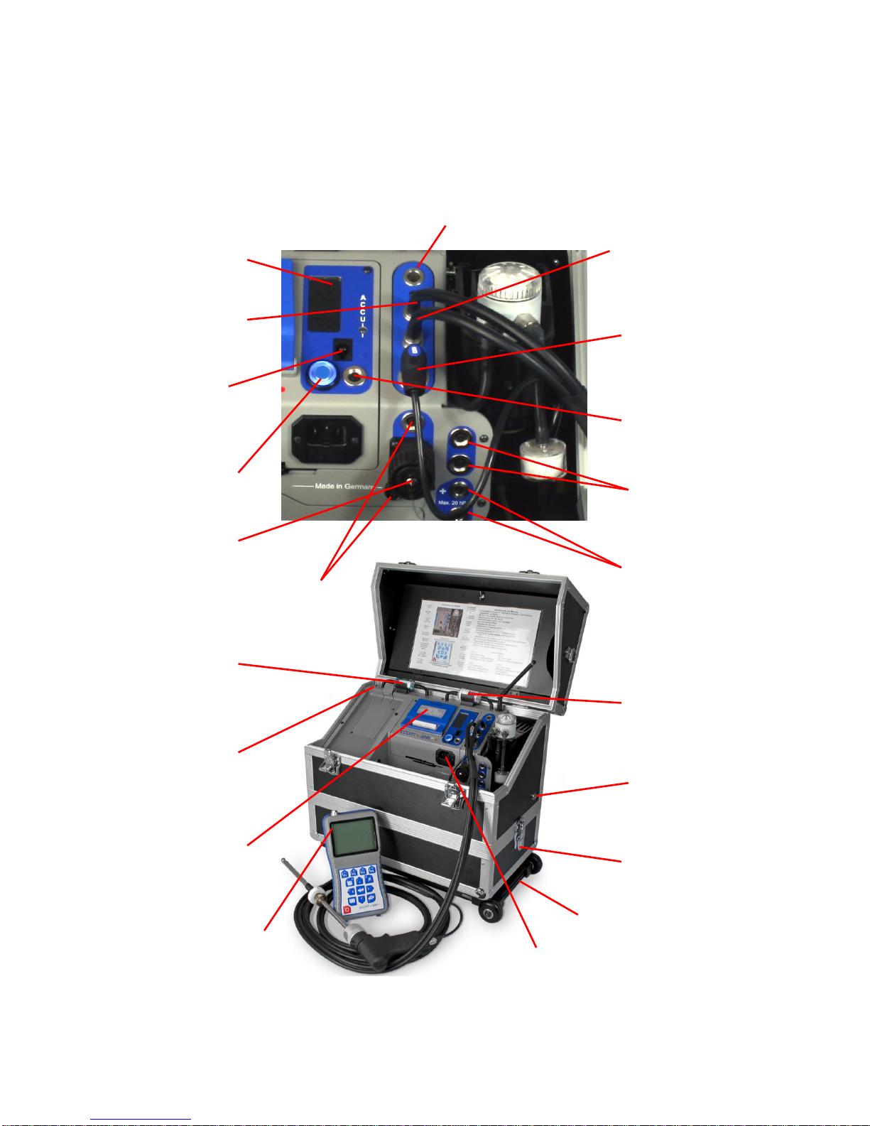
2. Instrument Design
2.1 J2KN Pro Base Unit
Ambient air
temperature
sensor
Thermocouple
connection
Main gas
connection
Draft/Pressure
connection
Draft/Pressure
connection
Water trap
drain hose
connection
On-board
printer
Filter for
IR bench
(if applicable)
Remote Display
Unit
(see next page)
Power cord
socket
Info display
(see 15. Control)
ON / OFF
button
Analogue
inputs
(optional)
Auxiliary
temperature
connections
Nox/SOx
filter for
CO sensor
Pitot tube
connections
(see 19. Flow
Measurement)
Data cable
connection
(used by ECOM
personnel only)
Under case
(optional)
Trolley w/ wheels
(optional)
Heated line power
supply connection
(optional)
Fresh Air
Bypass Switch
(Pro IN only)
Page 6
Page 6
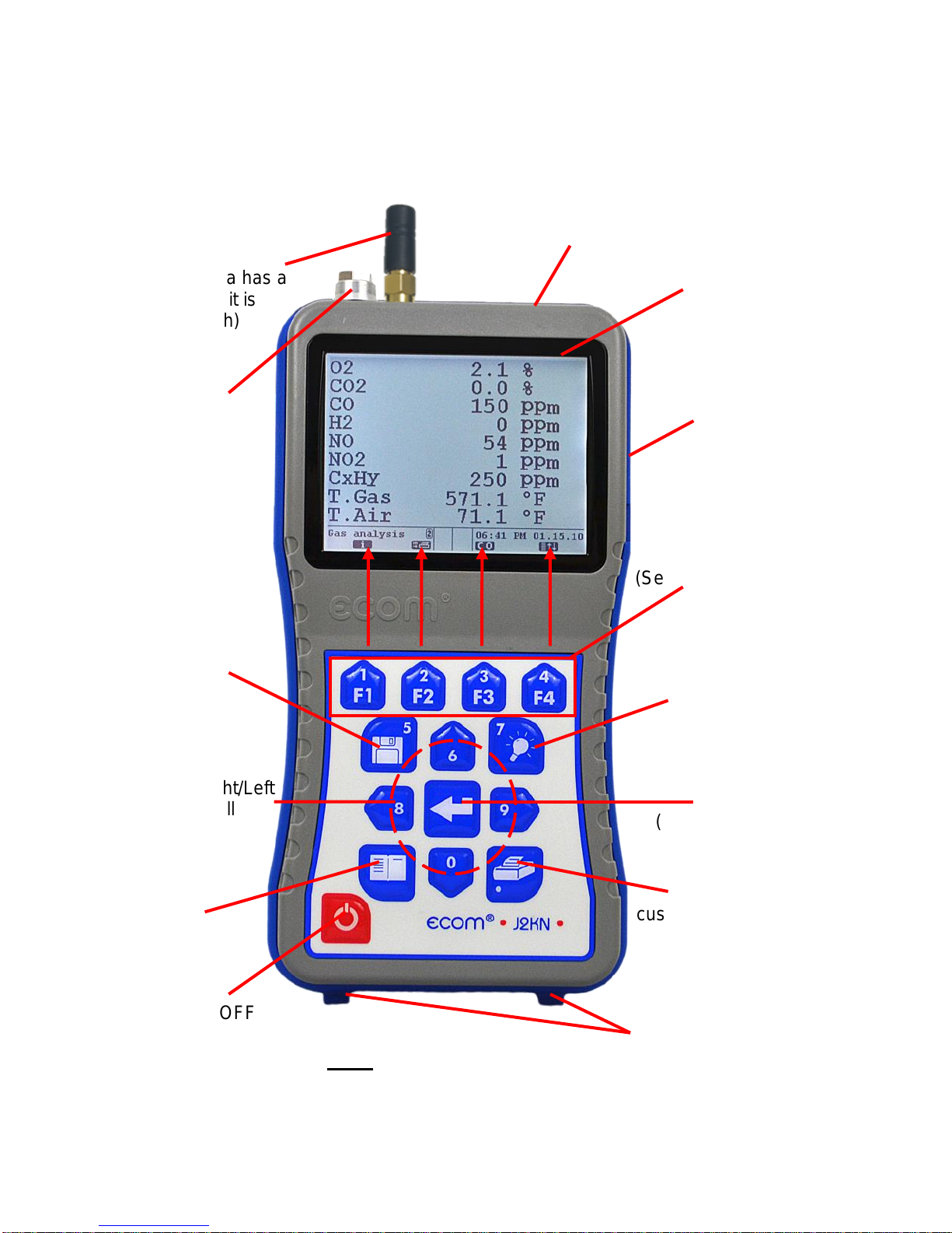
2. Instrument Design (continued)
2.2 J2KN Pro Remote Display Unit
Escape
Note: All keypad buttons
are used for input of num-
bers 0-9 and decimal point
OK
(press to confirm)
Up/Down/Right/Left
and Scroll
Capture data
Press to add
custom text to printout
(Press F2 to
print normally)
ON/OFF
Display
Backlight
ON/OFF
Function Keys
(See 8.1 Gas Analysis)
Memory card slot
LCD display
screen
USB
connection
Data cable sockets
(used by ECOM per-
sonnel only)
WiFi antenna
(If your antenna has a
pink band, it is
Bluetooth)
Air temperature
connection
(not an antenna)
Page 7
Page 7
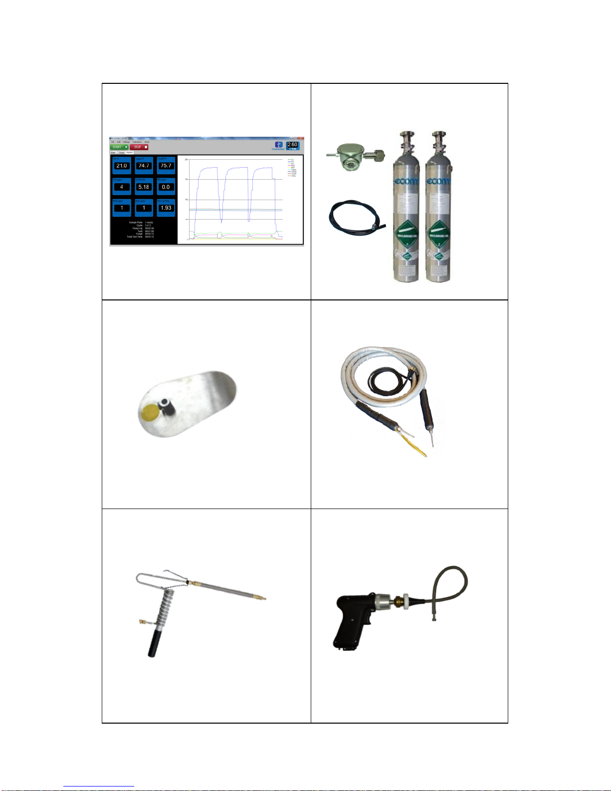
2.3 Accessories
e-Comply Testing Software
Part no. 9038001H
(Records mass emissions in
g/bhp-hr, lbs/hr, & tons/year)
Calibration Gas Kits
Part no. available upon request
Probe Shield
Part no. 3025006G
(Recommended for high temp
applications to protect grip)
15ft/30ft Heated Sample Line
Part no. 7952501H
(Custom lengths available
from 0 to 100ft)
Tail Pipe Probe Assembly
Part no. 7126631H
(Recommended for tail pipes
when inserting 180 into stream)
Flex-Tip Probe Assembly
Part no. 7129601H
(Recommended for hard-toaccess sampling ports)
Page 8
Page 8
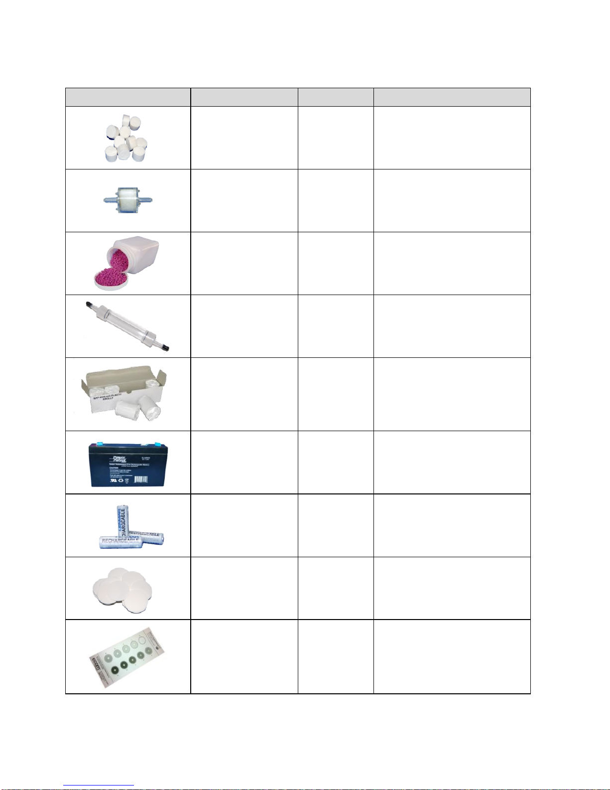
2.4 Consumables
PART
PART #
DESCRIPTION
Particulate
Filter (10/PK)
3015840G
10/PK - Particulate
filter located on top of
water trap assembly
In-line Smoke
Filter (1 EACH)
7118501H
1 EACH - Standard 3/4"
in-line filter in clear
plastic casing.
NOx/SOx Filter
Media (1LB)
3014457G
1LB - NOx/SOx filter
media refill container
(purple beads)
NOx/SOx
Media Tube
7128601H
NOx/SOx Media Tube
Thermal Onboard Printer
Paper (5/PK)
7927401H
5/PK - Printer paper for
on-board thermal
printer
J2KN-Pro Main
Battery
7929101H
Main Battery
J2KN-Pro
Remote Display
Batteries (3/PK)
7929201H
3/PK - Battery Pack for
Remote Display
Soot Test Paper
(200/PK)
3003168G
200/PK - Round smoke
test filters for smoke
dot test
Soot Test Chart
3002970G
Soot Test Chart with 09 Grayness Scale
*Please consult the J2KN Pro Parts List PDF for a list of all parts.
Page 9
Page 9
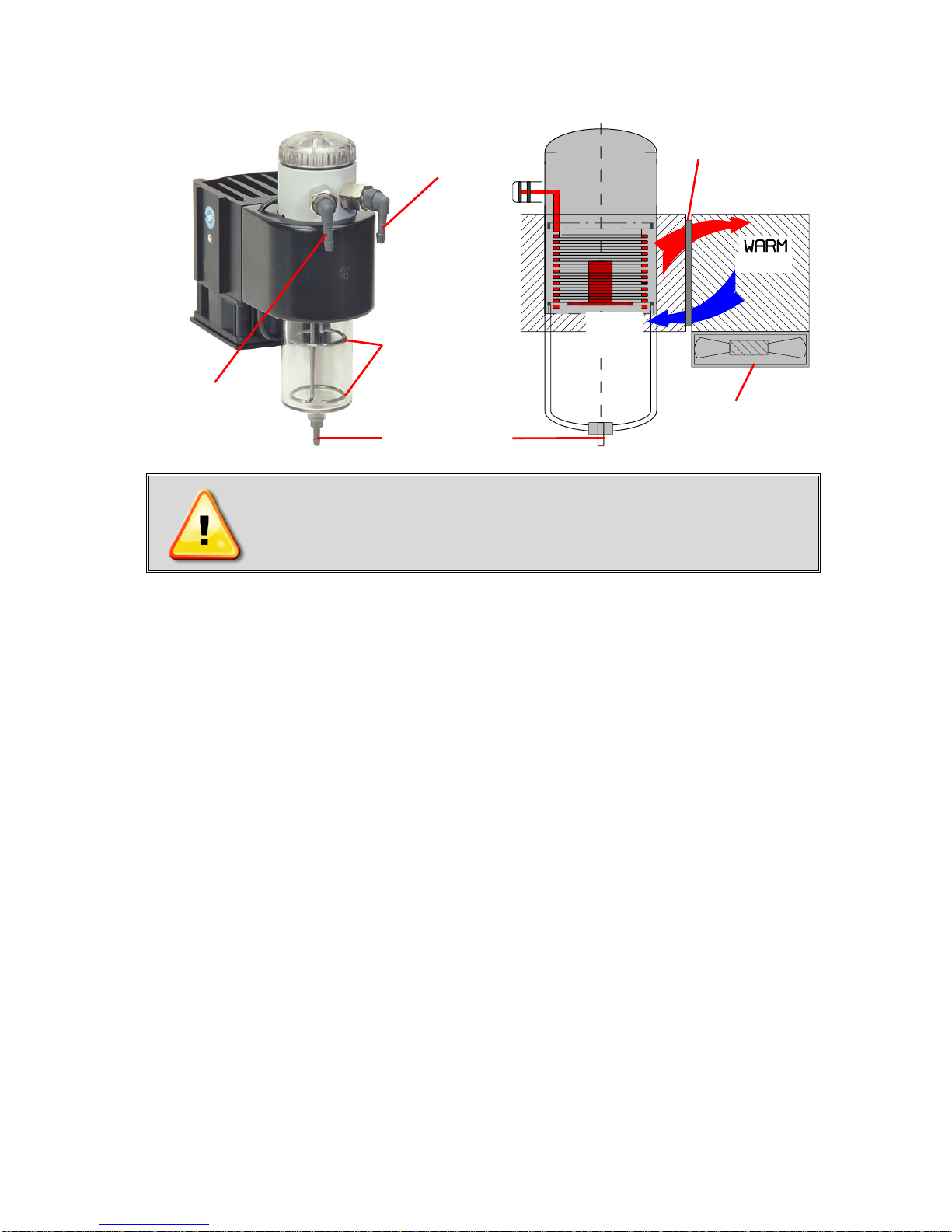
3. Peltier Cooler
J2KN Pro must be plugged in for the
Peltier cooler to operate.
Exhaust gas with a temperature above dew point is introduced into a spiralling gas path with a coated metal surface
of good thermal conductivity. The hot gas radiates its heat to
this metal coating, which is thermally connected to a Peltier
element and a second metal body with cooling ribs and ventilation slots. The flow thru the Peltier element creates a heat
transfer from WARM to COLD and this takes the heat from
the metal coating and transfers it to the outer cooling body.
The heat is then released to the surrounding air via a ventilation fan.
Condensation forms when the gas temperature drops below dew point. This moisture drains into the water trap bowl
and is pumped out by a peristaltic pump when the water
reaches a high enough level to link both monitoring electrodes.
The high speed pump allows for enough flow to avoid excess exposure time between the gas sample and water, so
that drop-out reactions (for example, NO2+H2O > H2NO3) do
not occur, which is necessary for measurement accuracy.
Fan
Peltier
Element
Gas
Outlet
Gas
Inlet
Water Level
Monitoring
Electrodes
Water drain
COLD
Page 10
Page 10
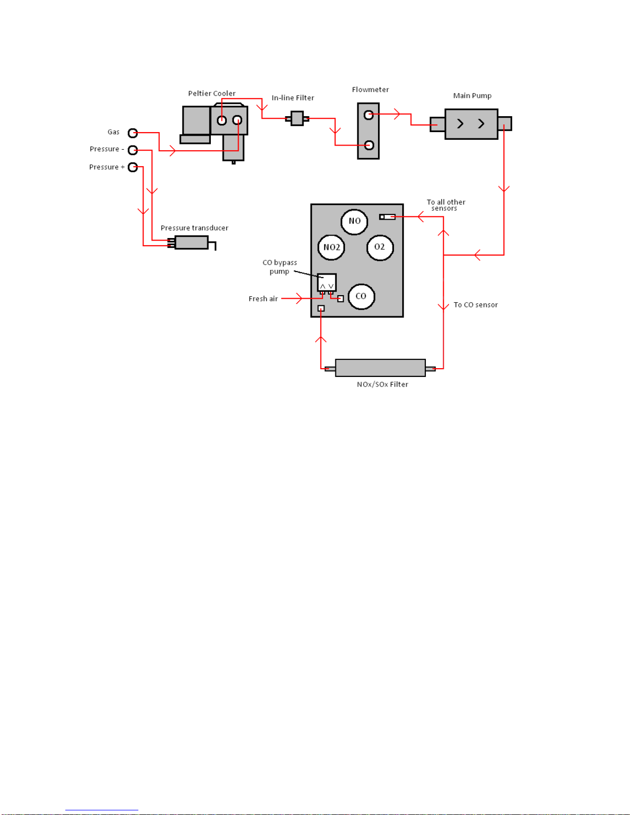
4. Gas Path Diagram
Response Time
After inserting the probe into the sample gas, there is a
short delay before the values start changing since the gas
has to pass through the sampling system. This is referred to
as response time, and it usually takes about 4-6 seconds for
the readings to start to change. Since the CO sensor has an
elongated gas path with the NOx/SOx filter (see diagram),
the response time for the CO is approximately 10 seconds.
Stabilization Time
Different from the response time is the stabilization time.
This is the time it takes for the sensors to build up a stable
electrochemical reaction in the electrolyte solution, and it
usually takes about 60-90 seconds for the readings to stabilize. NO2 readings may take slightly longer. For this reason,
wait 2-3 minutes for the readings to stabilize before printing
or recording emission results. Minor drifting of a few ppm can
be caused by minor pressure changes and may be negligible.
*All times listed here are based on using a 15ft sample line*
Page 11
Page 11
5. Power Supply
The J2KN Pro base unit has an internal power supply, and
it is recommended to always run the unit on AC power. For
testing locations where an AC plug-in is not available, the
instrument can be operated from 6-8 hours on battery power
when fully charged. Connecting the J2KN-Pro to AC power
charges the battery and is necessary to operate the Peltier
cooler and heated probe.
When the battery level gets low, the analyzer will start to
beep and display a low battery warning. The voltage reading
on the battery is displayed in the Control screen. The warning is activated when the charge drops below 6 V. When it
reaches 5.8V, the battery charge is not sufficient to power
the unit.
Only use batteries supplied by ECOM.
Contact ECOM with any questions.
The J2KN remote control unit is powered by 3 nickelmetal-hydride batteries (type AA). These batteries are recharged by docking the remote control unit onto the J2KN
base unit. To change the settings for recharging these batteries, go to:
Adjustments > Internal > Reload function > OK
1. Recharging function ON (<F1> = YES)
- Batteries slowly and carefully recharged
- Recommended for frequent use
2. Recharging function OFF (<F4> = NO)
- Batteries quickly recharged
- Recommended for occasional use
- Note: Battery run-time is reduced on quick charge!
1. Charge the battery after each use
2. Always store unit with fully charged battery
3. Charge the battery at least once a month if
not in use
Page 12
Page 12
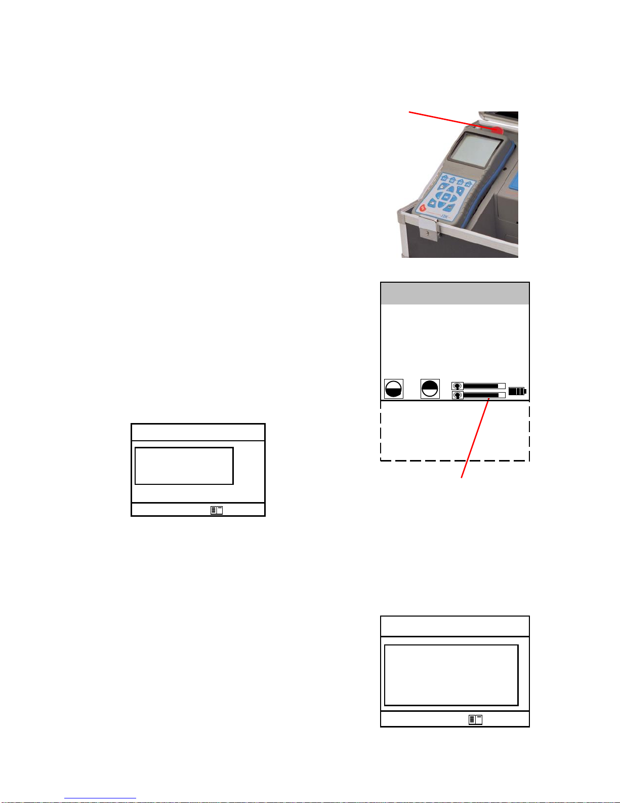
6. Radio Communication
The J2KN Pro base unit communicates wirelessly to the remote display
unit via radio transmisision. To unlock
the remote control unit, press on the tab
to unlock and release from the cradle on
the base unit.
The information exchange between
the remote control and base unit is
performed via radio transmission (915
MHz) with a coverage of approximately
100ft by free sight. The quality of the
radio transmission is documented by a
bar indication in the Main Menu.
If the J2KN base unit is switched off
and the remote control unit is on, the
display will show a message telling the
user to place the remote control unit
into the docking station (see below).
Troubleshooting Communication Issues
If there is interruption of the radio communication, an error
message is displayed (see below right). If this occurs frequently,
it may be necessary to re-sync the remote to the base unit:
1. Place remote unit into cradle
2. Go to Adjustments > Internal > RF
Connect > Standard > OK
3. The base and remote are now synced
4. Go to Adjustments > Internal > RF
Connect > Remote > OK
5. The remote can now be used as normal
Unlock
Bar indication
radio quality
-- ECOM-J2KN --
Radio connection
interrupted!
Use cable or
switch on basic
module!
Quit with:
-- ECOM-J2KN --
Place J2KN in
basic mod.!
Quit with:
Gas analysis
Averaging
Draft/Pressure
Soot Test
Automatic meas.
Adjustments
Control
Diagnostics
Page 13

Page 13
7. J2KN Pro Start-up
Make sure the probe is in fresh air when you
turn on the J2KN Pro.
1. Switch on the J2KN base unit and the remote control
unit. The Main Menu is displayed with 8 sub-menus:
- Gas analysis View gas readings & calculations
- Averaging Perform averaging tests
- Draft/Pressure Calibrate pressure sensor
- Soot Test Perform soot/smoke density test
- Automatic meas. Data logging onto memory card
(Pro Easy & IN) and set up automatic test cycles (Pro IN only)
- Adjustments Modify J2KN settings
- Control Diagnostic info/Calibration mode
- Diagnostics (Only used with ECOM AK tool)
2. Select Gas Analysis and press <OK>
3. Press Up/Down to select Fuel Type
and press <OK>
4. Analyzer will complete auto-zeroing
of all sensors, except the O2 sensor
which is calibrated to 20.9%
Fuel type
Gas-Natural
CO2max A1 B
11.7 0.35 0.006
Select: (
Radio Link
Quality Indicator
Battery Charging
Indicator
Display contrast:
Lighten F1
Darken F2
Gas analysis
Averaging
Draft/Pressure
Soot Test
Automatic meas.
Adjustments
Control
Diagnostics
Page 14

Page 14
8. Emissions Measurement
8.1 Gas Analysis
Calibrate the sensors before
each emission test for best results.
After the 1-minute auto-zeroing phase, the instrument switches
to Gas Analysis mode. The measurement values can be viewed
on 3 display pages: a zoomed in 4-line display and 2 full 9-line
displays. All line items are user-selectable (see Display Values
below). Press Up/Down to scroll between the pages.
Bypass Switch (Pro IN)..Turn on/off fresh air bypass to purge
Info Screen (Pro Easy)....View diagnostic info on Control screen
Quick Print............Prints on-screen measurement values
CO Bypass.............Manually turn on/off CO bypass pump
Display Lines.......Choose measurement values to display by
pressing F4 then Up/Down/Right/Left
To change F1 hotkey from default, go to
Adjustments > Internal > F1 Hotkey
Turn on CO bypass pump to protect CO
sensor from high concentrations
Pump automatically activates at 4000ppm!
To change F4 hotkey from default, go to
Adjustments > Internal > F4 Hotkey
Edit Display
Lines
<F4>
Control Screen (Pro Easy)
Purge Valve On/Off (Pro IN)
<F1>
F1:
F2:
F3:
F4:
Tip: To apply O2 correction, go
to Adjustments>Ref. O2 and input
your O2 correction % value. Then
go to Adjustments>Unit and change
unit to ppm %O2 corrected.
Quick Print
<F2>
CO Bypass
Pump ON/OFF
<F3>
O2 8.2 %
CO 431 ppm
NO 126 ppm
NO2 65 ppm
Gas Analysis 25.11.07
Page 15

Page 15
8.1 Gas Analysis (continued)
Heated Probe
If you are testing in a cold temperature environment, you
may require a heated probe so that condensation does not
form (or freeze) in the probe or probe grip. To turn on the
heated probe, go to Adjustments>Internal>Probe heat-
ing>F1. Remember to turn it off when the probe is not in
use, and allow the probe to cool before placing it in the case.
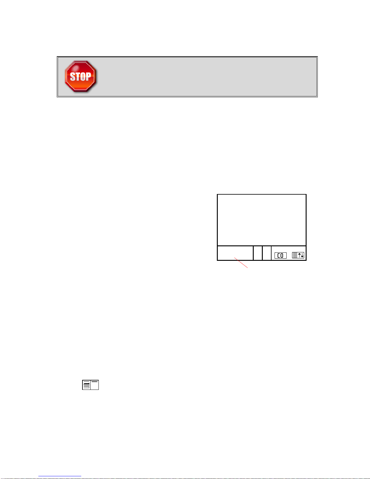
Core Stream Search
To obtain the most accurate gas
sample, the end of the probe should be
positioned in the center of the exhaust
stream or the “core stream.”
A + or – symbol displays in the core stream box (see figure above), indicating a trend towards positive or negative
temperature. As long as the display shows a + symbol, the
measured temperature is increasing and the probe tip is
moving towards the core stream. If a - symbol is displayed,
the measured temperature is decreasing and the probe tip is
past the core stream. Pull the probe back slightly to reach
the core stream, and adjust the probe cone so that the probe
is firmly in place.
Calculated Values
Calculated values include CO2, efficiency, losses, and excess air and are defined only when realistic values for O2 and
temperature are available. Otherwise, the values will dash
out on the display. For the calculated values to appear on the
display, the O2 concentration must be less than 20.5%
O
2
< 20.5 % and T.Gas - T.Air > +5°C
When these conditions are met, all calculations will display.
Gas temp. trend indicator
O2 8.2 %
CO 431 ppm
NO 126 ppm
NO2 65 ppm
Gas analysis
Gas stream
Probe tip
Thermocouple hook
Page 16
Page 16
8.2 Printing
Quick Print
The easiest and quickest way to print is to press <F2> for
quick print, which immediately prints the measurement values
currently on the screen. This also saves a snapshot to memory.
Print in Timed Intervals or Print an Average Over Time
To print in timed intervals (for example, every 10 seconds or
each minute) or to print an average over time, please refer to
10. Averaging Tests.
Print from Memory
1. Press 5/Save (disk icon)
2. Press Print key (printer icon)
3. Select Start printout
4. Press 5/Save to clear memory
Measurement recorded
Print with Text (i.e. site and equipment)
1. Press Print key (printer icon) to display printing options
2. Select Insert Text and press OK to select first line of text
(maximum 6 lines of text, 20 characters per line)
3. Using the directional keys and OK, select the alphanumeric
characters to insert text. Press F3 to change grid to lower case,
numbers, or other characters. To delete a character, press F4 to
toggle up then F2 to delete. Press F1 to accept text. If you wish
to insert more lines of text, select the next line and repeat.
4. Press twice to return to Gas Analysis
5. When ready to print, press <F2> for quick print
6. To clear text from printout, press Print key, select Insert Text,
select text line, press F4 to toggle up, move the cursor to the
right of the text, and press F2 to delete each character.
Wait for the measurement values to stabilize
for at least 2 minutes before printing the
results.
O2 8.2 %
CO 431 ppm
NO 126 ppm
NO2 65 ppm
Gas Analysis
Recorded!
Page 17

Page 17
8.3 Soot Test
The soot test is a measure of soot or
smoke density in the exhaust sample.
The soot test must be performed with the heated probe turned
on in order to prevent the filter paper from becoming wet due to
condensation. To turn probe heating on, go to
Adjustments > Internal > Probe heating > F1
J2KN Pro must be plugged in for the probe
heating function to activate. Allow 3 minutes
for the probe to heat up before soot test.
Soot Test Procedure
1. Turn on probe heating: Adjustments>Internal>Probe heating>F1
2. Press the trigger on the probe handle to open the filter slot
and insert a filter paper (will insert about half-way)
3. Select the line 1st. Soot meas
4. Press <OK> to start the measurement.
The display shows flow volume and the
pump starts sampling
5. Once 1.63 liters have been sucked in,
the J2KN-Pro will prompt to input the
opacity number
6. Press the trigger on the probe handle
to open filter slot and pull out the filter
paper
7. Compare the greyness on the filter paper with the soot test
chart 0-9 opacity scale
8. Input the number and press <OK>
9. Repeat steps 2-8 until all 3 soot tests are completed. The
mean value will be calculated and automatically stored.
10. Turn off probe heating: Adjustments->Internal->Probe heating->F4
Select NO for Oil trace.
Remember to let the probe cool down
before putting it back in the case.
Soot Test
Average: -.-
Boiler temp.: ---°F
1st Soot meas.: -.2nd Soot meas.: -.3rd Soot meas.: -.-
Oil trace : ----
Soot Test
Mean value: 5.0
Boiler temp.: 166°F
1st Soot meas.: 5.0
2nd Soot meas.: 4.5
3rd Soot meas.: 5.5
Oil trace : NO
Page 18

Page 18
9. Capturing Data on Memory Card (2GB max)
Data Logging in Timed Intervals
1. Go to Automatic Meas. > Save to MM
Card. This is the time interval that each
data point is recorded to the memory card
(min. 1sec, max 255sec). Input desired
amount in seconds and press OK.
2. Select Datalogger > “Start dl? Are you
sure?” > Press F1
3. Analyzer is now in Datalogging mode. The
blinking disk in the top right corner indicates that the analyzer
is currently logging data. Press to return to the main menu
and select Gas Analysis to view real-time measurements.
4. To complete data logging and save the file, press to return
to the main menu, go to Automatic Meas. > Datalogger >
“Finish dl? Are you sure?” > Press F1.
Capturing Data Snapshots On-Demand
1. Go to Automatic Meas. > Save to MM Card and input 255.
2. Select Datalogger > “Start dl? Are you sure?” -> Press F1
3. Press to return to the main menu and go to Gas Analysis
to view real-time measurements.
4. Press 5 (disk symbol). You will see an X over the disk icon
in the top right corner. This is normal and expected.
5. When you are ready to capture the first data point, press 5
(disk symbol), wait 2 seconds, and press 5 again. The
data point was captured during the 2 second interval.
6. Repeat step 5 for all desired data points.
7. To complete data collection and save the file, press to
return to the main menu, go to Automatic Meas., select
Datalogger -> “Finish dl? Are you sure?” -> Press F1.
Each data file will be saved separately as J2KDL-00, J2KDL-01, etc.
Open in Microsoft Excel. You can also import the data from the SD
card into ECOM’s free DAS 5 software to create formal reports.
Page 19

Page 19
10. Averaging Tests
The Averaging function allows you to take a sample of
emissions data and compute an average over time.
1. Go to Averaging -> Select Meas. Time
2. Input total measuring time in minutes or
seconds (for seconds, press decimal 1st)
3. Select Scanning and input interval time
in minutes or seconds
For example: If the Meas. Time is 1 minute and the
Scanning time is 10 seconds, the mean value will take
into account 6 scans and find the average
4. Select Printer and choose from the following options:
No Value. This prints only the final averaged values.
Each Value. This prints a snapshot for every scan.
Each Value of 2, 3, etc. This prints a snapshot for every
other scan, every third scan, etc.
5. Do not select Store. Please leave to default.
6. Select Start Measurement.
Mean value measurement has initiated.
Press up/down to toggle between mean
value and real-time results. You will see
the time counting down in the bottom
left of the display screen.
7. After the Meas. Time has elapsed, press Print key to print
averaged results if it does not print automatically
8. Press , select Averaging, and press F1 to quit
averaging calculation
Start measurement
Meas. time
Scanning
Printer
Store
Averaging
Quit with:
O2 3.2 %
CO2 13.1 %
CO 0 ppm
Eta 92.5 %
Losses 7.5 %
Lambda 1.18
T.Gas 184 °C
T.Air 20 °C
Averaging 25.11.07
15:59 min
Page 20

Page 20
11. Software Communication
If you need help with installation or operation of your DAS
or e-Comply software, please consult the User Manual for your
software product. If you are having trouble communicating
from the analyzer to a computer, please check the following:
Adjustments > Internal > RF Connect
Make sure it is in Remote setting.
Adjustments > Internal > USB
For both DAS and e-Comply, make sure the Baud rate is
38400 and the Protocol is enhanced.
Adjustments > Internal > WLAN (if applicable)
If you have WiFi communication problems, refresh the WiFi
signal by selecting Auto Connect > F1. You will see the IP
address dash out and come back again. Note: You can’t connect to both the software and mobile app simultaneously.
Adjustments > Internal > Bluetooth (if applicable)
For both DAS and e-Comply, make sure the Baud rate is
9600 and the Protocol is enhanced. To reset the Bluetooth
signal on your computer, right-click on > Show Bluetooth
Devices > Right-click on BT connection> Remove Device. Now
click Add a Device and re-connect to the analyzer. PIN=1234
If communication issues persist, re-sync the remote & base
1. Place remote unit into cradle. Go to Adjustments >
Internal > RF Connect and select Standard.
2. The base and remote are now synced.
3. Change the RF Connect setting back to Remote.
4. The remote can now be used as normal.
If all else fails, do a hard reset of the analyzer:
1. Power down the analyzer.
2. Disconnect analyzer from AC power.
3. Open the battery drawer and disconnect the lead from the
battery (white plastic clip). Wait at least 1 minute.
5. Reconnect the battery, reconnect the power cord, and
restart analyzer. You have just completed a hard reset.
Page 21

Page 21
12. Frequently Asked Questions
Where do I find important instrument information?
How long is the life span of the
sensors?
Which sensors can I exchange?
The instrument shows the error
message “O2 sensor 0 mV“
The instrument shows the error
message “T-Gas“ or “T-Air“
The instrument shows wrong or
inaccurately CO2 values
Can I change the printout?
In the Control screen, all important instrument information is shown (e.g. battery voltage, sensor values, serial number, next service date, operation hours, etc.).
The life span depends on the operating hours
and the instrument equipment. The life span
of the toxic sensors (CO, NO, SO2, NO2) is
affected by high gas concentrations or insufficient purging. The life span for these sensors
is on average 3 years. The life span of the O2
sensor is independent of the operating hours
and amounts to approximately 2 years.
The following sensors are exchangeable:
- O2 sensor
- CO sensor (pre-calibrated available)
- NO sensor (pre-calibrated available)
- NO2 sensor (pre-calibrated available)
- SO2 sensor (pre-calibrated available)
The O2 sensor must be changed.
Note: The error messages can be bypassed by
pressing . Calculations that rely on these
temperatures will not display.
Possible reasons could be:
- Cable is broken (at the plug)
- T-Air sensor error – check all connections
- T-Gas sensor error – check all connections
- Thermocouple is defective
Possible reasons could be:
- O2 is defective (CO2 values are calculated
from O2 value)
- Pump is not working correctly
- Air leakage in the gas path
- Peltier cooler is clogged
Yes, go to Adjustments > Internal > Printout
Page 22

Page 22
12. Frequently Asked Questions (continued)
If you have any further questions, do not hesitate to contact
the ECOM America Service Department at 770-532-3280
J2KN-Pro cannot be
switched on
J2KN-Pro doesn’t print all of
the values I want
Pump flow seems too low
The water is not pumping
out of the water trap bowl
When trying to connect using
software, the analyzer is not
connecting to my PC.
No flow is getting to the
sensors
J2KN-Pro display is blank
when I turn it on but the
analyzer is clearly powered
on
My memory card is not working
- Check the main power cable
- Check the fuse (located inside the power socket)
- Recharge the batteries for a minimum of 8 hours
(Battery could be completely discharged)
You must press F2 (quick print) while in Gas
Analysis to print all of the values on the screen.
Any dashed out values will not print. The button
with the printer icon is only for printing from
memory.
Check all hose connections for tearing/cracking
and check Peltier cooler for blockage
Check the white peristaltic tubing to make sure it’s
not pinched. If necessary, open up the unit and
check the rollers in the white housing. Call ECOM
service for assistance.
Check these 3 items:
1-Adjustments -> Internal -> RF Connect… Make
sure it is in Remote setting
2-Adjustments -> Internal -> Bluetooth… See
section 12.1 Internal for the correct setting
3-Adjustments -> Internal -> USB… See section
12.1 Internal for the correct setting
Check all connections and bypass the water trap to
pinpoint if the lead is in the water trap
Display contrast may be set incorrectly – press F2
many times after you turn on the remote unit to
see if screen comes back
Verify that you have a memory card storage of
between 32MB and 32GB
Hint: If you have several J2KN-Pro analyzers, you
can find the source of an error by exchanging the
accessories (probe, hose, temperature sensor, etc.)
Page 23

Page 23
13. Draft/Pressure
A trend indication for the draft conditions in the exhaust
channel is displayed in the Gas Analysis screen. Note that the
pressure sensor tends to drift because of its sensitivity, and it
is necessary to calibrate the sensor immediately before sampling to get an accurate measurement.
To calibrate, go to Draft/Pressure.
The current value is displayed. Disconnect the draft hose from the J2KN for a
short moment and press <F4>.
The pressure sensor is now calibrated.
Reconnect the draft hose. The display shows the current draft measurement value. This can be stored into
intermediate memory by pressing
5/Save. The stored value is shown on
the display. Press to quit the differential pressure menu.
14. Adjustments
Most of the settings of the J2KN-Pro
that are user-selectable can be changed
in Adjustments in the Main Menu.
Auto-Zero (J2KN-Pro IN only)
Press <OK> to set new zero points
for sensors. Before using this function,
the sensors must be flushed with fresh
air, and the J2KN-Pro IN must be in a
fresh air environment during the autozero phase.
Unit
The default setting for gas concentration units is ppm
(parts per million). The options for units include:
Auto-Zero
Unit
Mass Emission
Ref. O2
Fuel type
Set clock
Paper feed
Internal
Air Leak Test
Quit with:
Page 24

Page 24
14. Adjustments (continued)
Mass Emissions
The J2KN-Pro calculates mass emissions in units of lbs/hour, tons/year,
or gr/bhp. First, under Adjustments, set the Unit to ppm and choose
the correct Fuel Type. Then select Mass Emission and press <OK>.
Press up/down to select the correct unit.
For lbs/hour or tons/year:
For gr/bhp:
-If fuel flow is known, press F2 to
input Fuel consumption (scf/hr for
gaseous fuel & gal/hr for liquid fuel)
-If fuel flow is known, press F2 to input Fuel
consumption (scf/hr for gaseous fuel &
gal/hr for liquid fuel)
-If fuel flow is not known, press F4 to
input mmBTU/hr for a calculated
fuel consumption
-If fuel flow is not known, press F4 to input
mmBTU/hr for a calculated fuel consumption
-No need to input Horsepower@test
-Press F3 to input Horsepower@test
-Press <OK> to accept
-Press <OK> to accept
Ref. O2
Enter the reference %O2 value using
the number keys and decimal point.
The conversion equation is shown to
the right. You must then change the
Unit to %O2 corrected.
Fuel type
Options for fuel type include natural gas, propane, butane, diesel, oil,
coal, and wood. This is necessary for CO2 and Mass Emissions calcs.
Set clock
Set time and date
Paper feed
Press <OK> to start paper feed and to end paper feed
Air leak test
Cover the end of the probe with the yellow cap supplied with the unit and
press <OK> to start checking the sampling system for air leaks.
E
ref
= E
meas
*
21 - O
2 ref.
21 - O
2 meas.
ppm parts per million
mg/m3 milligrams per cubic meter
mg/kWh %O2 Corrected milligrams per kilowatt-hours corrected to O2%
mg/MJ %O2 Corrected milligrams per megajoules corrected to O2%
ppm %O2 Corrected parts per million corrected to O2%
mg/m3 %O2 Corrected milligrams per cubic meter corrected to O2%
lbs/mmBTU %O2 Corrected pounds per million BTU corrected to O2%
Page 25

Page 25
14.1 Internal
(Go to Adjustments > Internal)
Print contrast
Choose print contrast from 0-9
Reload function
Choose remote unit battery recharging
settings (see 5. Power Supply)
Key beep
Press F1/F4 to turn key beep on/off
Graphic menu
Press F1/F4 to turn graphic menu on/off
Probe heating
Press F1/F4 to turn probe heating on/off
for soot measurement test (see 8.3 Soot
Measurement Test)
Power saving mode
Press F1/F4 to turn on/off power saving
mode, which turns off the Peltier cooler
and the heated probe option
Language: English
Press OK to choose between French and English
F1 Hotkey
Press Up/Down to choose F1 shortcut (see 8.1 Gas Analysis)
F4 Hotkey
Press Up/Down to choose F4 shortcut (see 8.1 Gas Analysis)
Eff.(C)
Press F1/F4 to turn on/off the efficiency calculation with and without condensation
C/F
Press up/down to choose your temperature unit and then press OK
RF-connect
-Standard: choose this option to sync the base and remote units if
radio communication problems occur
-RF-connection: do not choose this option
-Remote: allows for remote operation of controller (default)
Printout contrast
Reload function
Key beep
Graphic menu
Probe heating
Power saving mode
Language: English
F1 Hotkey
F4 Hotkey
Eff.(C)
°C/°F
RF-connect
USB
Bluetooth
Pitot Factor
Printout
Quit with:
Page 26

Page 26
14.1 Internal (continued)
USB
For DAS 5 & e-Comply: Set Baud rate to 38400
Set Protocol to Enhanced
WLAN (if applicable)
Wireless Local Area Network. If you have internal WiFi, this
option will appear and the IP address will display at the bottom
-Access point: turn on/off internal WiFi
-Auto connect: if turned on, WiFi will intitiate upon start-up
-Channel: change the WLAN channel if interference occurs
(If WiFi communication errors occur, go to this screen and select Access point and press F1. This will refresh the IP address.)
Bluetooth (if applicable)
For DAS 5 & e-Comply: Set Baud rate to 9600
Set Protocol to Enhanced
The first time you connect to a computer
via Bluetooth, use “1234” pairing PIN.
Pitot factor
(See section 19. Flow Velocity Measurement)
Printout
This feature allows you to add 8 lines of text at the bottom of
the printout at 20 characters per line. Usually this is reserved
for company information such as company name, address,
phone number, and website. (To add a special note for a specific test, please see 8.2 Printing.)
To change printout text, press Up/Down to select the line you
would like to edit. Press F4 to toggle up and down between the
insert text box and the alphanumeric grid. Using the directional
keys and OK, select the characters to insert text. Press F3 to
change grid to lower case, numbers, or other characters. To
delete a character, press F4 to toggle up, then F2 to delete.
Press F1 to accept text and continue to the next line.
Page 27

Page 27
15. Control
The electrochemical sensors change their output values
over time based on frequency of use. The J2KN-Pro is programmed to monitor the sensors and correct drifts. If the
drifts and the correlated measurement errors increase, an error message is displayed and it is time to change the sensor.
The control menu displays the status of the sensors, batteries, radio quality, error count, number of times the J2KN-Pro
has started up, and other analyzer information.
Info Display
2.24
ltr /
min
Main pump is running
Fresh air valve is open
CO purging is running
Gas cooler ready for use
Heated line ready for use
Heated head ready for use
Probe heating is switched on
Gas flow
(liters per minute)
Radio mode
Battery operation
Calibration phase
O2 10744 mV
CO 7 mV
Batt 4.50 V
Bat.B 6.09 V
Operation hours : 8.45 hrs
Serial no. : J2KN 12345
Service tel. : 02371-945-5
Programm version : V3.0 / 12.07.10
Next unit check : 20.04.11
Control
20
4.2 /s
4.2 /s
0.0 /s
1 X
22 ppm
4 X
11 X
-rbr- Messtechnik O2 10744 mV
Am Großen Teich 2 CO 7 mV
58640 Iserlohn Batt 4.50 V
--------------------- Bat.B 6.09 V
Tel.: 02371-945-5
Fax : 02371-40305
eMail : info@rbr.de
Operation hours : 8.45 hrs
Serial no. : J2KN 12345
Service tel. : 02371-945-5
Programm version : V3.0 / 12.07.10
Next unit check : 20.04.11
Control
Company name
on printout
(editable)
Serial number
Firmware
version
Radio quality
Radio frame
rate (sent)
Radio frame
rate (received)
USB frame rate
Battery voltage
Batt. = remote
Batt.B = base
Operation hours
Recommended
maintenance date
CO bypass coun-
ter
PPM hours of CO
sensor
Error counter
J2KN start-up
counter
Millivoltage of
sensors
(see section 16.3)
Page 28

Page 28
16. Maintenance Tips
Only use sensors, filters, and filter media
provided by ECOM. Do not use desiccant!
16.1 Filters
Particulate filter (water trap filter)
Unscrew the cover of the water trap and check the particulate filter for grayness. Change the filter when it is dark gray.
Tip: use the elbow piece as a reference since it is dark gray.
In-line smoke filter
The round in-line smoke filter should be checked periodically
for grayness. Change the filter when it is dark gray. Tip: use
the elbow piece as a reference since it is dark gray.
NOx/SOx filter
The CO sensor has an independent gas path (see 4. Gas
Path Diagram) which includes a potassium permanganate
chemical filter for filtering SO2 and NOx from the gas sample.
Color change: purple -> brown -> grey-> white
Filter media should be changed once it has turned grey!
Particulate filter
In-line smoke filter
Elbow piece
Page 29

Page 29
16.1 Filters (continued)
Ventilation filter
The ventilation filter should be changed if the filter has a
darkness of 2-3 on the soot chart scale. Use a screwdriver to
pry open the filter holder from the slots on each side. Change
the filter cartridge and refasten the filter holder.
Ventilation filter
Filter cartridge
Filter holder
16.2 Sample Line and Probe
The sample line and probe should be cleaned regularly to
release particle deposits and to prevent early wearing due to
corrosion.
To clean the hose, disconnect from the analyzer end and
the probe end, blow out the line with short bursts of air from
an air compressor, and hang up to dry overnight so that excess water may drain out.
16.3 Sensors
During the J2KN-Pro start-up procedure, each sensor is zeroed using fresh air as the reference point, except for the O2
sensor which is calibrated to 20.9%. The status of each sensor is permanently monitored by the instrument. The sensor’s
life span is shortened by the exposure to high concentration
gases above the measurement range. The output values of
the sensors should be in the range of:
O2 OO/105 (white) 11000 mV to 13000 mV
O2 5FO (black) 17000 mV to 24000 mV
All others -100 mV to +100 mV
If an error message is displayed during the start-up phase
and cannot be cleared despite several restart attempts,
please call an authorized service center for troubleshooting
advice.
Slots
Page 30
Page 30
16.3 Sensors (continued)
The CO sensor is protected from exposure to high concentrations by the automatic CO bypass pump. If the limit
value of 4000 ppm is exceeded, a second pump switches on
and purges the sensor with fresh air.
14.4 Printer Paper
To change the printer paper, please follow these steps:
1. Release the printer cover
2. Take out the used paper roll
3. Remove the used paper roll from the shaft and place the
new paper roll onto the shaft
4. Insert the paper end into the black ribbon cartridge slot
5. Feed approximately 2 inches of paper by going to
Adjustments > Paper feed and pressing <OK>
6. Place new paper roll and shaft back into place
7. Insert the paper end into the blue printer cover slot
8. Close the printer cover
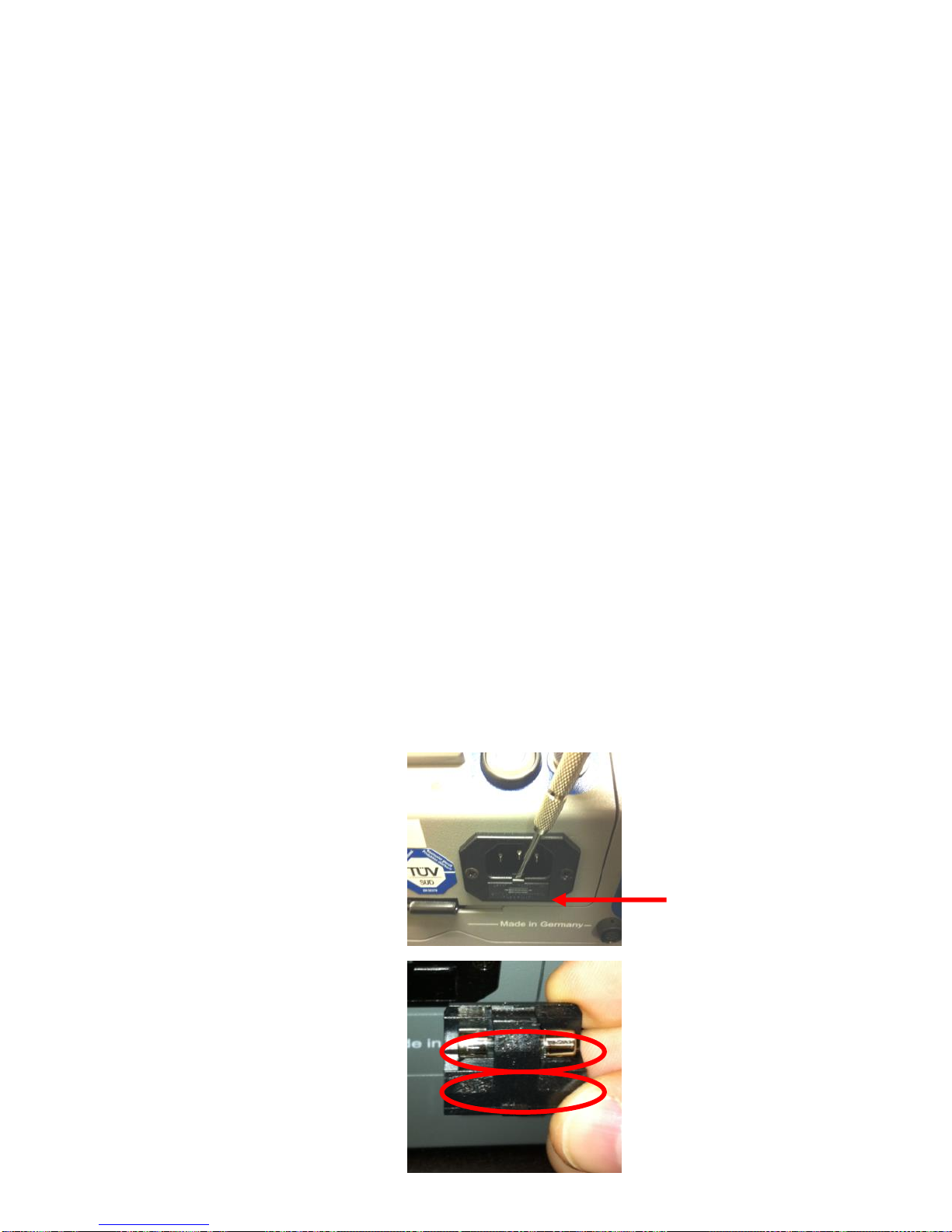
16.5 Changing the Fuse
A 1 amp fuse is located in a small drawer just below the
power cord socket. If the J2KN-Pro is not powering up when
plugged into AC power, this may be due to a blown fuse. To
change the fuse, please follow these steps:
1. Use a small
screwdriver to
release the fuse
drawer
2. Take out the
spare fuse and
insert into the
active fuse spot
3. Re-insert fuse
drawer
Fuse drawer
Active fuse (exposed)
Spare fuse (hidden)
Page 31

Page 31
17. How to Change Sensors
17.1 How to Change O2 Sensor
Step 1:
Use a T-10
torx wrench
to remove
screws from
O2/CO cover
plate
Step 2:
The O2
sensor is
attached to
2 wires,
located
below the
CO sensor
Step 3:
Disconnect
the lead
wires and
unscrew
counter
clockwise
until loose,
then pull
directly out
Step 4:
Install new
O2 sensor
by screwing
clockwise
until locked
& reconnect
wires
Improper installation voids warranty!
Please mark connector when removing old
sensor and insert new sensor into correct
connector to prevent destruction of the
sensor and main board.
Step 5: Replace O2/CO cover plate and tighten screws with a T-10 torx
wrench
Step 6: Turn on analyzer and select Gas Analysis to start self-calibration
of O2 sensor to 20.9% in ambient air (must be in fresh air)
Page 32

Page 32
17.2 How to Change A5F CO Sensor
Step 1:
Use T-10 torx
wrench to
remove
screws from
O2/CO cover
plate
Step 2:
The A5F CO
sensor is in
gray
housing
attached to
a ribbon
cable
Step 3:
Disconnect
ribbon cable
from CO
sensor
Step 4:
Remove CO
sensor using
coin or
fingers
Turn 45
degrees
counter
clockwise
and pull
directly out
(continued on next page)
Improper installation voids warranty!
Please mark connector when removing old
sensor and insert new sensor into correct
connector to prevent destruction of the
sensor and main board.
Page 33

Page 33
17.2 How to Change A5F CO Sensor (continued)
Step 5:
Pop open the
gray cap
using a small
screwdriver
Use the side
of the housing as a
leverage
point
Step 6:
After the
cap is
removed,
slide the
sensor out
of the
housing as
shown here
Step 7:
Remove the
board from
the sensor
using a small
screwdriver
Warning! PTC
embedded in glue
Pry from beneath the
dried glue so the PTC
does not separate from
the board
Failure to do so may
destroy PTC
Step 8: Place board onto new sensor
Step 9: Insert new sensor into gray housing and replace cap by
snapping into place
Step 10: Insert new sensor into analyzer, turn 45 degrees clockwise
to lock into place and replace ribbon cable
Step 11: Replace O2/CO cover plate and tighten screws with T-10
torx wrench
Step 12: Calibrate your new CO sensor using certified calibration gas
Page 34

Page 34
18. How to Calibrate Sensors
For best results, the calibration gas concentration should be as
close to the expected levels of emissions as possible. However,
because each sensor is linear through a nominal range, one calibration
gas concentration can be used for a reasonably wide range of emission
levels. For applications with extremely low or extremely high levels of
emissions, you will need to tailor your calibration gases accordingly.
Fully charge analyzer:
Place unit on charge the night before you plan to use analyzer to
ensure full charge of battery.
Initiate analyzer:
1. Attach T-gas thermocouple, sample line, and power cord.
2. Switch on analyzer.
3. Select Gas Analysis on main menu.
4. Select Fuel Type, press OK.
5. Allow instrument to complete self-calibration/auto-zero sequence.
Put analyzer in calibration mode:
1. Press to return to main menu and go down to select Control.
2. While in the Control screen, swipe calibration magnet over the Cal
Magnet sticker, located at bottom left of keypad.
3. The analyzer is now in calibration mode. You will see the sensor
readings with a cursor that you can move up and down. The O2%
reading is located at the bottom of the screen.
Check for air leaks:
1. To check for air leaks, you must introduce a gas with zero O2%
through the entire sample train. This is necessary to check that the
system has no leaks to atmosphere. We recommend NO gas
balanced in N2 because you can check for air leaks and calibrate the
NO sensor at the same time (2 birds, one stone). If you have a
CO/NO mix balanced in N2, you can use this as your leak check gas
as well (3 birds, one stone).
2. To connect the calibration gas cylinder to the analyzer, use one of
the following three set-ups:
Page 35

Page 35
18. How to Calibrate Sensors (continued)
On-Demand Regulator: (Recommended) Use an on-demand
regulator which uses the analyzer pump draw to establish flow.
Connect the on-demand regulator to the sample train and open
the cylinder valve. The analyzer pump controls the flow as to not
over or under pressurize the sensors.
Adjustable Flow Meter: Connect an adjustable flow meter to the
sample train and measure the pump draw. Then connect the gas.
Use the cylinder valve for course adjustments and the flow meter
for fine adjustments to match the flow of the pump draw.
Vented Flow Meter: Connect a vented flow meter to the sample
train and connect the gas. Open the cylinder valve until a small
amount of gas is exiting through the vented flow meter. This
prevents air from entering system and allows pump to control
internal pressure within analyzer.
3. After you have connected the gas to the analyzer, watch the O2
reading until it is 0.0%. If it does not reach 0.0%, you may have
an air leak. Troubleshoot the source of the leak and correct it. It is
also possible that the system is tight but your O2 sensor is aged.
4. Do not proceed to calibrate the analyzer until you have verified that
the O2 reading goes down to 0.0%!
Calibrate your analyzer:
1. Apply the gas and wait for the reading to stabilize. (If you used a
cal gas for the leak test, the readings should be stabilized already.)
2. After the reading has stabilized, you may calibrate the sensor. To
calibrate, move the cursor beside the target sensor and press OK.
Input the concentration value from the gas cylinder and press OK.
3. The reading will change to the calibration gas value. Watch the
reading to make sure it doesn’t drift. If it does, wait until it stabilizes and re-calibrate. If it keeps drifting, the sensor may be aged.
4. After you have verified calibration, disconnect the gas.
5. Repeat steps 1-4 for each sensor.
6. After the calibration is complete, allow the analyzer to flush with
fresh air for 5 minutes or until readings are below 10 ppm.
Page 36

Page 36
19. Flow Velocity Measurement (Option)
Stack flow or exhaust gas flow can be measured by the
J2KN-Pro using a special flow probe. If you are using a standard
ECOM probe, set this to 0.93.
First, the Pitot factor must be entered in the Adjustments
menu to get the correct flow rate calculation. Input 0.93 for the
Pitot factor if you are using a standard ECOM probe. To do this,
go to:
Adjustments > Internal > Pitot factor
After connecting the Pitot tube to the
analyzer, go to Flow Measurement
Press <F4> to set the zero point of the
flow sensor.
Press <F1> to input the cross section
of the stack or exhaust stream, which
is required for the flow rate calculation.
Position the Pitot tube in the stack or
exhaust stream.
The display will show the speed (m/s),
flow rate (Nm3/h) and differential pressure (Pa). After the values have stabilized, press <F2> to print the results.
*Call ECOM at 877-326-6411 if you would like the flow measurement
option added to your J2KN-Pro. You will have to get a return authorization number and send the analyzer to our service department in Gainesville, Georgia, USA.
V.Gas 0.4 m/sek
M.Flow 44 Nm3/h
dP 0.1 Pa
Flow measurem.
25.11.07
Flow measurement
Connections for
pitot tube
Measurement stored in
intermediate memory
Page 37

Page 37
20. Technical Data
Parameter Range Principle
O2 0 ... 21.0 vol-% Electrochemical
CO 0 ... 4000 ppm Electrochemical
CO% (Option) 4000 ... 63000 ppm Electrochemical
NO 0 ... 5000 ppm Electrochemical
NO2 0 ... 500 ppm Electrochemical
SO2 (Option) 0 ... 5000 ppm Electrochemical
CxHY (Option) 0 ... 4.00 vol-% (CH4) Catalytic
CxHY (Option) 0 ... 2000 ppm (C3H8) Infrared
CxHY (Option) 0 ... 3.00 vol-% (CH4) Infrared
CO% (Option) 0 ... 63000 ppm Infrared
CO2 (Option) 0 ... 20.0 vol-% Infrared
Air pressure 300 ... 1100 hPa DMS bridge
CO2 0 ... CO2max Calculation
T-Gas 0 ... 1000 °C NiCr/Ni
T-Air 0 ... 99 °C Semi-conductor
Differential pressure 0 ... +/- 100 hPa DMS bridge
Efficiency 0 ... 120 % Calculation
Losses 0 ... 99.9 % Calculation
Excess air 1 ... Calculation
Op. Temp: 20-122°F
CO sensor purges thru separate fresh air pump
Electronic water trap monitoring with Peltier cooler
Power Supply Main Power 110V...60 Hz / 220V...50 Hz
Base Unit Battery 6V/7.0 AH Lead Acid
Remote Unit Batteries AA Nickel Metal Hydride (set of 3)
Pump Flow rate of 2.0+ lpm
On-board Printer Thermal printer / 58mm paper width
Display Screen LCD Display with Backlight
Dimensions (LxWxH) (Pro Easy) 17.5 x 9.75 x 12 inches
(Pro IN) 20 x 9.75 x 12 inches
Weight (Pro Easy) 28 lbs with sampling system
(Pro IN) 29 lbs with sampling system
Subject to technical changes
V3.6.2 / January 2015
Page 38

Page 38
21. Description of Data Fields using J2KN-Pro
Data Logging onto Memory Card
File format: J2KDL-xx.csv (comma-separated-values)
Column
Description
Remark / Example
A
Date
DD.MM.YYYY
B
Time
HH:MM:SS
C
O2 in vol.%
0.0 – 21.0
D
CO in ppm
0 – 4000
E
NO in ppm
0 – 4000
F
NO2 in ppm
0 – 500
G
SO2 in ppm
0 – 5000
H
CO converted*
CO corrected to reference O2%
I
NO converted*
NO corrected to reference O2%
J
NO2 converted*
NO2 corrected to reference O2%
K
NOX converted*
NOx corrected to reference O2%
L
SO2 converted*
SO2 corrected to reference O2%
M
T. Gas in °C or °F
0 – max temp.
N
T. Air in °C or °F
0 – max temp.
O
Draft in hPa
0.00 – 20.00
P
CO2 in vol.%
0.0 – 25.0
Q
Efficiency in %
0.0 – 120.0
R
Losses in %
0.0 – 100.0
S
Excess air
> 1.00
T
Dew point in °C or °F
0 – max temp.
U
Poisoning index
> 0.0
V
O2 (gas channel check) in vol.%
0.0 – 21.0
W
CO (gas channel check) in ppm
Related to 0.0 vol.% O2
X
CO (gas channel check) in ppm
Measured value
Y
O2 (O2 check) in vol.%
0.0 – 21.0
Z
T. Boiler
0 - 999
AA
T. Sensor
0 - 99
AB
O2 reference %
0.0 – 21.0
AC
Unit
0=ppm 1=mg/m3 2=mg/kWh 3=mg/MJ
AD
Norm
N = corrected to reference O2%
AE
Fuel type number
Index acc. to instrument table
AF
Fuel type text
Text acc. to instrument table
AG
Soot 1
0.0 – 9.9
AH
Soot 1
0.0 – 9.9
AI
Soot 1
0.0 – 9.9
AJ
Oil trace
0=no 1=yes
AK
20 characters text
AL
20 characters text
AM
16 characters text
AN
Serial number
AO
CO (O2 check) in ppm
AP
Zug (O2 check) in hPa
AQ
CxHy
AR
Number copy data
AS
T1 (T-measurement)
AT
T2 (T-measurement)
AU
Velocity
m/s
AV-AW
Comma
Reserved
AX
Comment text
AY
Comment text
AZ
Comment text
BA
Comment text
BB
H2 in ppm
BC
H2 converted*
H2 corrected to reference O2%
BD
Sensor # 6 in ppm
BE
Sensor 6 converted *
Sensor 6 corrected to reference O2%
BF
dP (velocity) in Pa
0 – 1000.00
BG
Air pressure in hPa
300 – 1100
BI-BM
Mass emissions
lbs/hr, gr/bhp, tons/year
BQ
Internal flow in lpm
0.00-3.00
* converted to unit (column AC) and converted on O2 ref. (Column AB) when column AD = N
Page 39

Page 39
22. Calculations
Note: A1, B, CO2max & Eta
max
are constants based on fuel type.
Excess Air (Lambda) Range=1-infinity
Excess air =
21
21 – O2 measured
Combustion Efficiency (Eta) Range=0-99.9%
Efficiency = Eta
max
- ( A1
+ B) x (T
Gas
– T
Air
)
CO2
Carbon Dioxide (CO2) Range=0-CO2max
CO2 = CO2 max
X (21 – O2 measured)
21
Losses Range=0-99.9%
Losses = 100 – Efficiency
O2 Correction Range=0-max
E
O2%
= E
meas
*
21 - O
2
reference
21 - O
2
measured
Page 40

Page 40
RUGGED. RELIABLE. ACCURATE.
ECOM AMERICA LTD
1628 OAKBROOK DRIVE
GAINESVILLE, GA 30507
TOLL FREE (877) 326-6411
PHONE (770) 532-3280
FAX (770) 532-3620
ecom.info@ecomusa.com
w w w . e c o m u s a . c o m
 Loading...