

Page 1

Operating Instructions
The ecom-EN3 meets the requirements of the
DIN EN 50379 Part 2.
Page 2
SAFTEY INSTRUCTIONS
Please observe all safety instructions in this manual carefully, in order to avoid danger and
damage to people and property values.
REGULATIONS
The ecom-EN3 meets the requirements of:
- DIN EN 50379 Part 2
- VDI 4206 Sheet 1
Observe the relevant, valid standards, regulations and guidelines when working with the
instrument!
TARGET GROUP
This manual is intended exclusively for authorized professionals.
WARNING
Adjustments at burners and boilers should be made only by specialists who
are familiar with these installations.
Symbols
WARNING
Indicates that personal injury, or even life-threatening injury, may occur.
DANGER
Indicates how the hazard can be avoided.
Indicates that material damage can occur.
Indicates how the hazard can be avoided.
In both cases it is stated how the danger can be avoided.
Hints
Hints are marked with an information symbol.
Text sections marked with an arrow call for an action.
Page 2 ecom-EN3
Page 3

WARNING
The ecom
-
EN3 is explicitly NOT intended for the following applications:
or processes
DANGER
The following substances impair the instrument´s operation:
- Formaldehyde
Information on the instrument
INTENDED USE
The ecom-EN3 is designed for the following applications:
- Analysis of exhaust gases from combustion processes in combustion engines
and combustion plants in the context of control measurements
- Analysis of pressure differences in combustion engines and combustion plants
- CONTINUOUS analysis of exhaust gases from combustion processes
- Use as a safety device or safety alarm device in gaseous environments
- Solvent-containing vapours from cleaning agents,
degreasers, wax polishes, adhesives
The unauthorized use leads to the exclusion of any liability claims.
LIFE EXPECTANCIES SENSORS AND BATTERY
Following life expectancies apply to sensors and battery:
- O2 sensor: approx. 4 years
- CO sensor: approx. 4 years
- Li-Ion battery: approx. 2 years
CE DECLARATION OF CONFORMITY
The product complies with the relevant directives and is therefore CE marked. The
conformity declaration can be requested from the manufacturer.
HINT
Strong electromagnetic fields can impair the function of the measuring instrument.
Make sure that the measuring instrument is not exposed to strong
electromagnetic radiation sources.
DISPOSAL
- Dispose the packaging material of the instrument in an environmentally sound manner.
- Old electrical equipment must be disposed in an environmentally sound manner by an
authorized body. On request, we take back your old instrument purchased from us
and guarantee for an environmentally friendly disposal.
- Defective batteries can be dispensed both at the factory and at the collection
points of public waste disposal companies or at points of sale for rechargeable
batteries!
ecom-EN3
Page 3
Page 4

WARNING
Electric shock!
Current
-
carrying components at
open housing
!
instrument from the mains supply at all poles.
Before opening the instrument housing, disconnect the
WARNING
DANGER
The instrument is operated with a Li-Ion battery!
The replacement of the battery must be carried out only by qualified
personnel or by an ecom authorized service center.
Electrostatic discharge!
Electrostatic discharge can lead to damage to electronic components!
Before handling the housing, ensure that you are unloaded. To do
this, touch a grounded component (eg water pipes, radiators, etc.).
Page 4 ecom-EN3
Page 5

ecom-EN3
Page 5
Page 6

Content
Information on the instrument 3
1. Instrument Design 8
1.1 ecom-EN3/-R, Transport variant aluminium-framed transport case 8
1.2 ecom-EN3-F, Transport variant professional case 9
1.3 ecom-EN3, Keyboard controls 10
1.4 ecom-EN3, Connections at the instrument 11
1.5 ecom-EN3, Option heated probe for soot measurement 12
1.6 ecom-EN3, Option hand soot pump set 13
1.7 Gas Cooler (Option) 14
1.8 Data Memory 15
1.9 ecom-EN3, Option Interfac Wi-Fi (WLAN) 16
1.10 ecom-EN3, Option interface BLE (Bluetooth Low Energy) 16
2. Measurement Preparations 17
2.1 Turn on the instrument and check the battery 17
2.2 Navigation in the menu 18
2.3 Calibration of the sensors, use of the database and fuel type selection 19
3. Carry out gas analysis 21
4. Measurement procedure gas analysis 22
4.1 Gas analysis 22
4.1.1 Adaptation of the displays for gas analysis 23
4.1.2 Positioning the probe, search the core stream 23
4.1.3 Printing measured values 24
4.1.4 CO-Overload Protcektion 25
4.2 Measurement procedure gas analysis: CO measurement 26
4.3 Measurement procedure gas analysis: O2 Check 27
4.4 Measurement procedure gas analysis: Draught measurement 27
4.5 Measurement procedure gas analysis: Flow measurement pitot tube (option) 28
4.6 Measurement procedure gas analysis: Soot...Oil trace 28
4.6.1 Soot measurement 29
4.6.2 Oil trace 29
4.7 Measurement procedure gas analysis: Data processing 30
4.7.1 Create new 30
4.7.2 Memory number 31
4.7.3 Search word 32
5. Measurement procedure mean values 33
6. Measurement procedure Diagnostics 35
6.1 Fault diagnostic 35
6.2 delta-T Measurement 37
6.3 Heating Check (option) 38
6.4 4 Pa Measurement (option) 41
6.5 Pressure Tests (option) 42
6.5.1 Pressure Test 43
6.5.2 Loading Test 44
6.5.3 Tightness Test 45
6.5.4 Usage property 46
Page 6 ecom-EN3
Page 7

7. After Measurement 48
7.1 Save measurement, print measurement 48
7.2 To-Dos before switching off 49
8. Control 50
9. Adjustments 51
10. Data processing 56
10.1 Storage on MM card 56
10.2 Data logger 57
10.3 Data connection to PC 58
10.3.1 Data recording with PC Software ecom-DAS NT 2 58
10.3.2 Data recording with PC Software ecom-DAS 5 59
10.3.3 Data recording with PC Software: Import and Export of Data 60
10.4 Data recording with App via WiFi 61
10.5 Data recording with App via BLE 62
11. Maintenance Tips 63
11.1 Fine dust filter 63
11.2 Gas sensors 64
11.3 Probe and tubing 64
11.4 Printer paper 65
11.5 Air leak test 66
12. Technical Data 67
ecom-EN3
Page 7
Page 8
1. Instrument Design
1
2
3
1
2
3 4 5 6
7
10
12
14
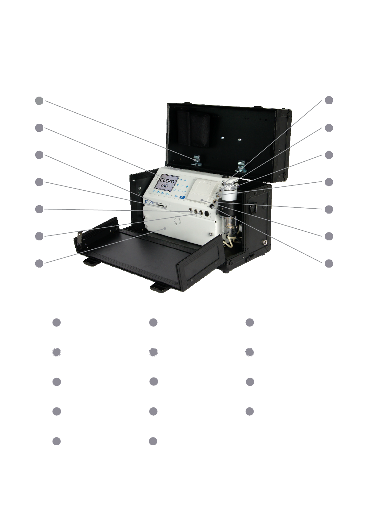
1.1 ecom-EN3/-R, Transport variant aluminium-framed transport case
Holding clamp for
the probe
Graphic display
Slot for multi-media
card (SD)
8
9
11
13
Page 8
4
Connection USB
7
Battery and sensors
compartment
10
Condensation trap (with
peltier cooler) with fine
dust filter
13
Integral thermal printer
5
Connections for Pa
pressure sensor
8
Connection sampled gas
11
Connection gas temperature
14
Connection AUX
6
9
12
Connection pressure
Connection draught
Connection air
temperature
ecom-EN3
Page 9
1 2
3
4 5 6 7
11
13 14
6
10
11 12
13
14
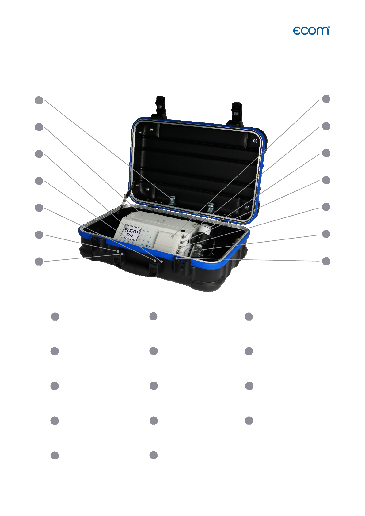
Connection USB
1.2 ecom-EN3-F, Transport variant professional case
Holding clamp for
1
the probe
Battery and sensors
2
compartment
Graphic display
3
8
9
10
12
4
7
ecom-EN3
Connection
Pressure
Condensation trap
(with Peltier cooler)
with fine dust filter
Connection air
temperature
Connections for Pa
5
pressure sensor
Integral thermal printer
8
Connection draught
Connection AUX
Slot for multi-media
card (SD)
Connection sampled gas
9
Connection gas
temperature
Page 9
Page 10
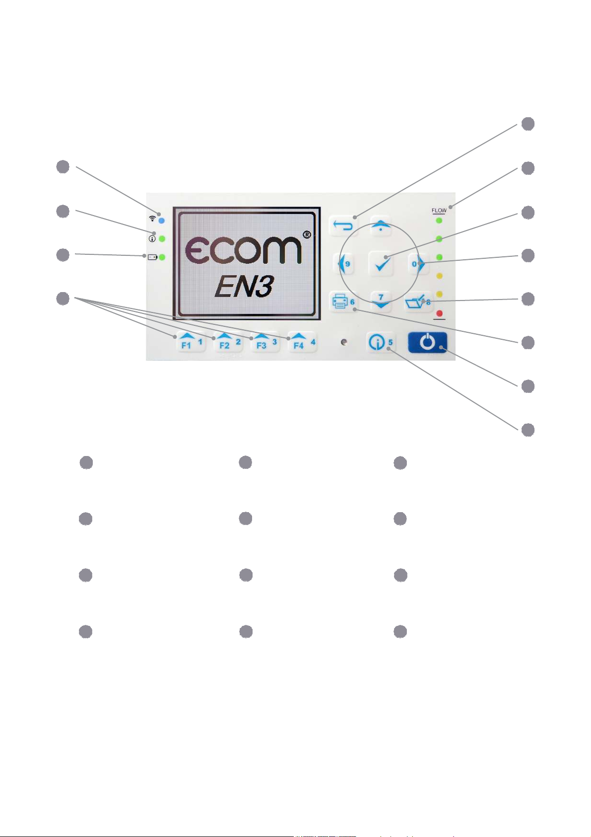
1.3 ecom-EN3, Keyboard controls
5 8 9 10 11 12
8 9
10
11 12
Battery LED to display the
Enter key (confirm
1
6
2
7
3
4
Connection LED (active with
1
existing BT or WiFi connection)
Info LED to display the
2
device status
3
charge state
Page 10
Function key (function
4
shown on display)
7
selection)
Print key
ESC key (quit/exit menu)
5
Digital flowmeter
6
Cursor keys
Save key
(Up/Down/Right/Left/Scroll)
ON / OFF key
Info key (access to control
menu)
ecom-EN3
Page 11
4
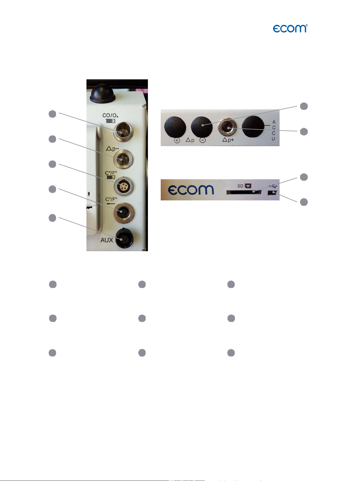
1.4 ecom-EN3, Connections at the instrument
1
2
3
4
5
1
Connection sampled gas Connection draught
2 3
Connection gas temperature
6
7
8
9
Connection air temperature Connection AUX Connection Pa-Sensor
7 9
Connection pressure
ecom-EN3
5 6
8
Slot for multi-media
card
Connection
USB
Page 11
Page 12
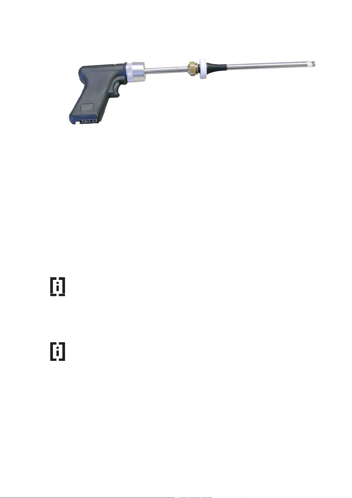
1.5 ecom-EN3, Option heated probe for soot measurement
Heated probe for soot measurement
In order to perform a measurement of the soot content in the flue gas from oil firing systems,
a filter paper is introduced into the exhaust path of the probe where the soot deposits during
the measurement.
On the basis of the deposited amount of soot on the filter paper (blackening), it is possible to
compare optically with a scale, which is the soot number. This makes it possible to evaluate
the amount of soot in the flue gas.
The filter paper is heated in the probe to prevent the flue gas from cooling too much. This
cooling of the flue gas would lead to condensation of water vapour from the flue gas and will
distort the result of the measurement.
Hint
As an alternative to the heated probe, a hand soot pump can be used. The
possible condensation of water vapour is however not prevented with a hand
soot pump.
Hint
For further information on the procedure for soot measurement with the heated
probe, please refer to chapter "4.7 Soot...Oil trace"
Page 12
ecom-EN3
Page 13
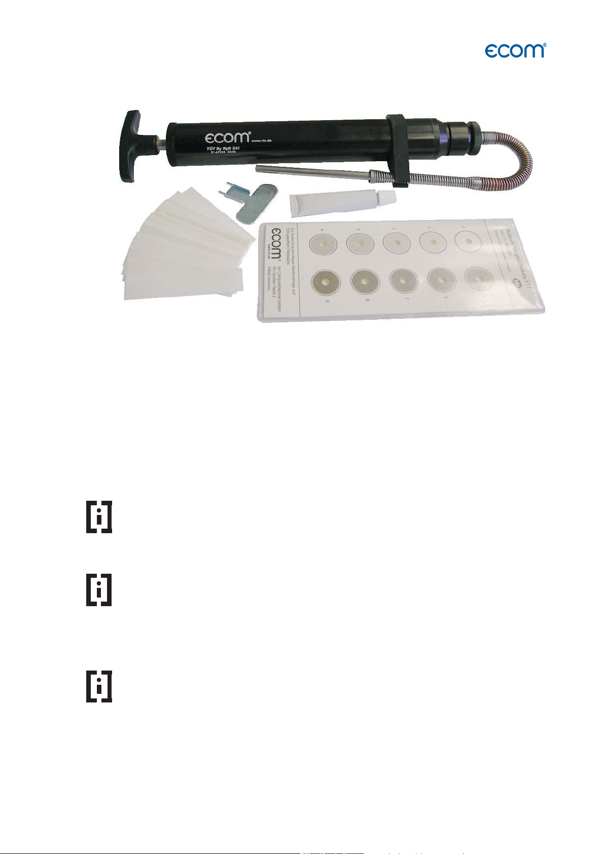
1.6 ecom-EN3, Option hand soot pump set
Hand soot pump set
In order to perform a soot measurement in the flue gas from oil firing systems, a hand soot
pump can be used.
By a prescribed number of suction strokes with the hand soot pump, a defined amount of flue
gas is drawn through an inserted filter paper. On the basis of the deposited amount of soot
on the filter paper (blackening), it is possible to compare optically with a scale, which is the
soot number. This makes it possible to evaluate the amount of soot in the flue gas.
Hint
The hand soot pump is TÜV tested and characterized by high quality in its
processing and construction. This guarantees a long-term reliable function.
Hint
As an alternative to the hand soot pump, a heated probe can be connected
directly to the measuring instrument. With this heated probe, the possible
condensation of water vapour and thus falsification of the measuring result
can be reliably prevented.
Hint
For further information on the procedure for soot measurement with the hand
soot pump, please refer to the manual for the hand soot pump set.
ecom-EN3
Page 13
Page 14
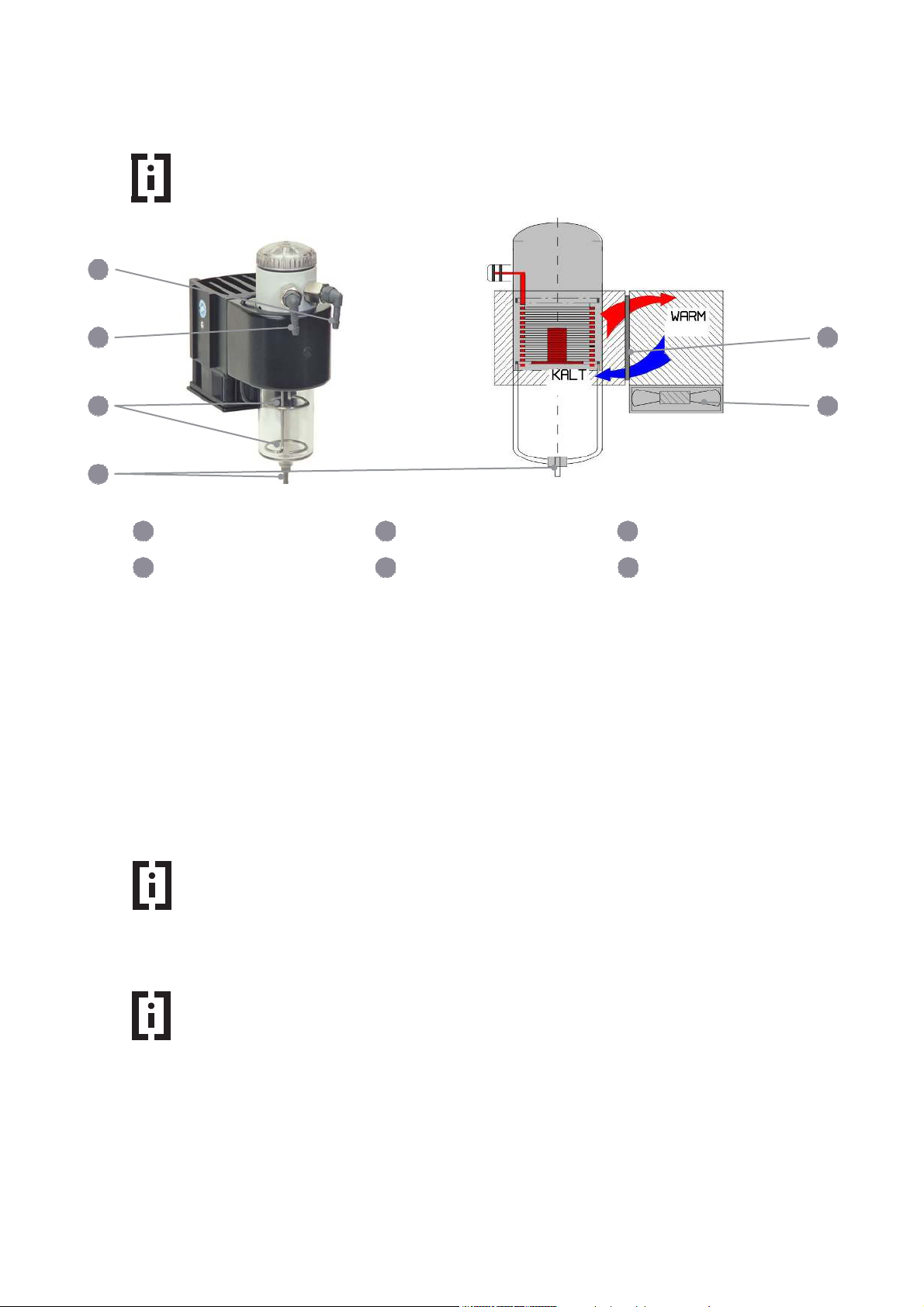
1.7 Gas Cooler (option)
6 1 4
Hint
The ecom-EN3-F transport variant professional case is standard with a gas
cooler.
1
2
3
4
5
Gas outlet Gas inlet Level monitoring
Condensate
evacuation
Exhaust gas with a temperature over the steam dew point (35 - 65 °C) is flown spiral via a
long gas path thru a surface coated metal body with good thermal conductivity. The gas
radiates its heat to this metal body. A Peltier element (semi-conductor cooling element) flown
by a continuous current is thermal connected with this body and with a second metal body
with cooling ribs and ventilation slots.
The flow thru the Peltier element creates a heat transfer from WARM to COLD, drains the
heat of the metal body flown by gas and conveys it to the outer cooling body. This heat is
conveyed thru a vertical forced ventilation to the surrounding air.
The condensation issued by the heat loss of the gas drops in a receptacle and is pumped out
on request by a periodically working hose pump.
2 3
5 6
Peltier element Fan
Hint
When the gas cooler is active, the power requirement of the instrument
increases considerably. Therefore the cooling capacity of the gas cooler in the
battery operation is reduced.
Hint
The gas cooler can be deactivated in battery operation.
To deactivate the activated gas cooler, press the <Enter>
key when the measuring menu is active. Choose the menu
point "Peltier I / 0" and press the <Enter> key again.
To reactivate the deactivated gas cooler, repeat the
above steps.
Page 14
ecom-EN3
Page 15
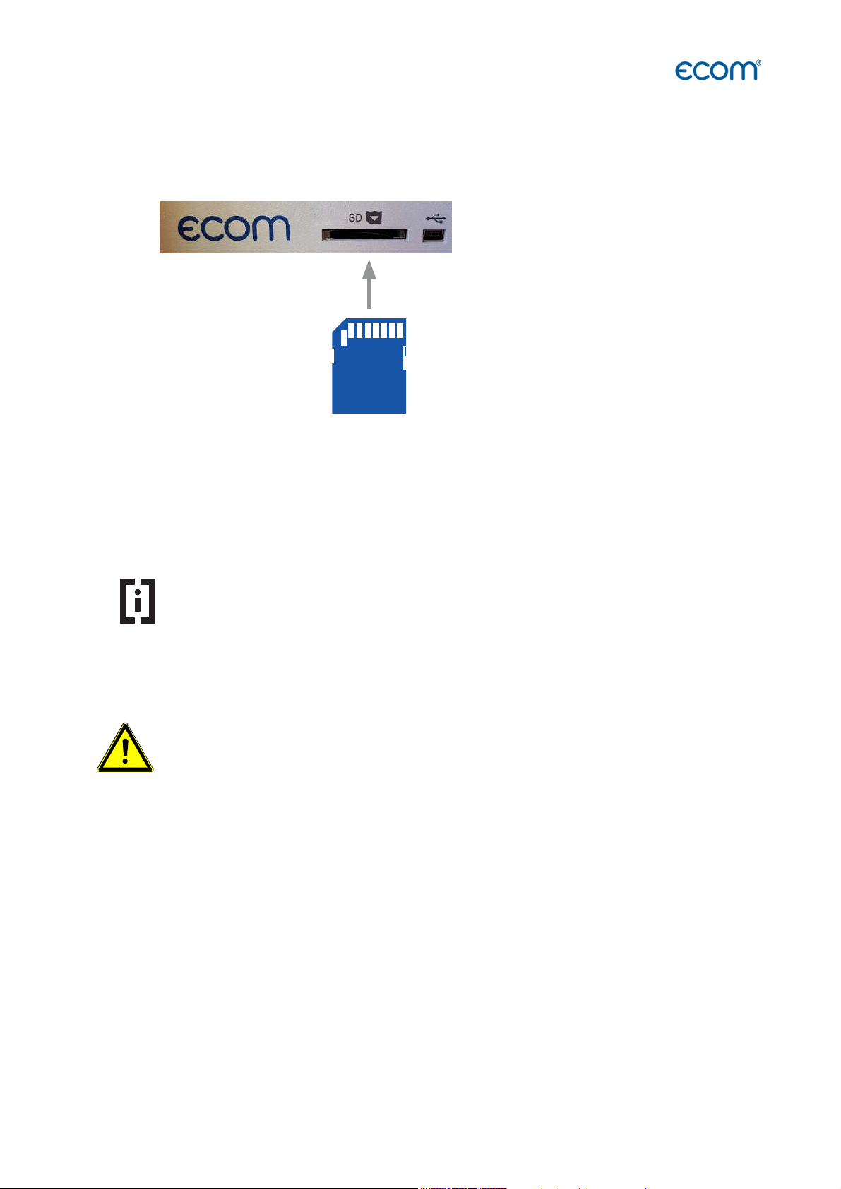
1.8 Data Memory
When an SD card is inserted into the device, point measurements and data logger records
can be stored.
Insert SD card as shown
°
To start point measurements or data logger records, insert the SD card as
shown in the SD card slot and let it fully engage.
WARNING
All values of a point measurement are stored in a text file with the name "J2KDV-xx.txt". The
text file is stored automatically in the main directory of the SD card.
All values of a data logger record are stored in a csv file with the naming
"J2KDL-xx.csv". Sequential files are automatically numbered from 0 ... 99.
The data in the text file and the csv file are stored in the same structure.
You will find further information on the data format in the chapter "Technical data".
The files can be transferred to a PC using a card reader. Both file types can be imported or
opened using MS Excel.
Hint
The SD card must have the following characteristics:
- min. card volume 32 MB - max.32 GB (UHC)
- card formatted on 16 bit FAT or FAT32
Never pull out cards during data record - data loss and damaging of the multimedia-card are possible!
ecom-EN3
Page 15
Page 16

1.9 ecom-EN3, Option Interface Wi-Fi (WLAN)
If the instrument is equipped with the Wi-Fi option, this interface can be used to display the
current measured values in an App of ecom. The following functions can be used in the App:
- Live display of current measured values
- Export of stored measured values as * .pdf or * .csv
- Activate the function "Print measured values" on the measuring instrument
- Activate the function "fresh air purge CO sensor" on the measuring instrument
Hint
For the start-up of the Wi-Fi interface and for further information on the
corresponding settings, please refer to the chapter "Adjustments".
1.10 ecom-EN3, Option interface BLE (Bluetooth Low Energy)
If the device is equipped with the BLE option, this interface can be used to display the current
measured values in an App of ecom. The following functions can be used in the App:
- Live display of current measured values
- Export of the stored measured values as * .pdf or * .csv
- Activate the function "Print measured values" on the measuring instrument
- Activate the function "fresh air purge CO sensor" on the measuring instrument
Hint
For the start-up of the BLE interface and for further information on the
corresponding settings, please refer to the chapter "Adjustments".
Page 16
ecom-EN3
Page 17
2. Measurement Preparations
Hint
Make sure that before each measurement
- the device has no visible defects
- the measuring system is tight (see leak test chapter 11.5)
2.1 Turn on the instrument and check the battery
The instrument is switched on with the <I / 0> key.
Hint
After switching on the instrument or before starting a measurement, check the
charging status of the battery.
Check the charging status of the battery in the status line and /
or in the menu "Control".
The instrument is supplied with charging power supply. The instrument can also be operated
with the internal battery for an extended period of time.
When recharging the battery is necessary, the instrument will emit a battery warning. This is
done acoustically and via a message in the display.
Hint
The battery warning is activated when the battery voltage is less than 6.5
V. Less than 6.0 V the operation with battery is no longer possible
The operation must continue via the charging power
supply.
WARNING
ecom-EN3
The instrument is operated with a Li-Ion battery!
The battery must be replaced only by qualified personnel or by ecom or an
ecom authorized service center.
Page 17
Page 18

2.2 Navigation in the menu
Gas analysis
When the instrument is switched on, the start screen is displayed, followed by the main menu.
Soot..Oil trace
Data processing
Adjustments
Control
Diagnostics
menu. Hidden submenus can be displayed by scrolling with
the arrow keys.
Menu Meaning Comment
Up to 5 submenus are displayed simultaneously in the main
Gas analysis Perform gas analysis
Mean value Perform gas analysis with mean value calculation
Soot...Oil trace Input of soot measurement results Start soot measurement (units with soot
Data processing Assign measurements / Data transfer only with inserted MM card
Adjustments Modify instrument adjustments
Control Check operation state of instrument
Diagnostics - Read-out of firing automate Only with ecom-AK
- delta-T measurement
- Heating check
- 4 Pa test
measurement)
Page 18
ecom-EN3
Page 19

YES
NO
CO2max
A1
B
15.4 0.50 0.007
Select:
2.3 Calibration of the sensors, use of the database and fuel type selection
Before you can start the measurement procedures, the instrument performs the following
steps:
1. Automatic adjustment of the sensors (calibration phase)
2. Query: Use of the database
3. Query: Selection of the fuel type
Select the sub-menu "Gas analysis" and confirm with <Enter>.
The instrument starts the automatic calibration of the sensors (calibration phase). This
calibration phase is completed after 60 s.
Hint
Position the probe only in the exhaust pipe when the calibration phase of 60 s
has been completed!
While the calibration phase is active, the query for using the
Do you wish to
use the data
processing?
Select:
database is displayed:
If the measured values of the subsequent gas analysis are to
be assigned to a plant or a customer, confirm the query with
"Yes".
Press the <F1> key.
For the following steps see chapter "4.8 Data processing during the measurement"
If the measured values of the subsequent gas analysis are not to be assigned to a plant or to
a customer, e.g. for a fast control measurement, confirm the query with "No".
Press the <F1> key.
Then select which fuel type is used in the combustion.
Fuel type
Fuel oil
To scroll through the list of fuel types stored in the
instrument, scroll up or down with the arrow keys.
Select the appropriate fuel by confirming with the
<Enter> key.
ecom-EN3
Page 19
Page 20
The following fuel types are stored in the instrument as standard:
Fuel type CO2 max Factor A2 Factor B
Fuel oil 15,4 0,68 0,007
Natural gas 11,8 0,66 0,009
City gas 11,7 0,63 0,011
Coke oven gas 10,2 0,60 0,011
Liquid gas 14,0 0,63 0,008
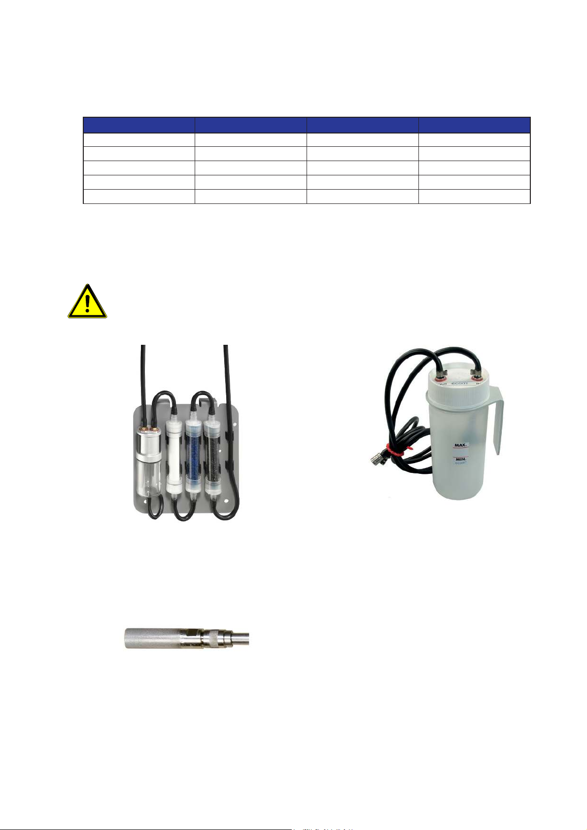
WARNING
For the combustion of solid fuels (wood / pellets / wood chips), a filtering
device recommended by ecom must always be used (see illustration)!
Filter plate for combustion of solid fuels Washing bottle for combustion of solid fuels
Probe prefilter
Page 20
ecom-EN3
Page 21

3. Carry out gas analysis
If the calibration has been successfully completed and all previous queries have been
answered, the instrument is ready for operation.
Hint
The following minimum times must be observed in order to obtain correct
measured values:
- 1 minute for fresh air calibration of the sensors
- 2 minutes for stable measured values at the instrument
Hint
To obtain accurate measurement values it’s important to re-calibrate the
instrument after each measurement (at the latest after one hour)!
- Switch off the instrument and wait for the switch off phase
- Switch on the device and refer to chapter "2. Measurement Preparations".
The current measured values of the active sensors are displayed in the measurement menu.
In addition, various measuring procedures are available:
Display Meaning Comment
Gas analysis 1 Display of 4 definable measured values Select the measured values with the <F4>
Gas analysis 2 Display of 4 definable measured values Select the measured values with the <F4>
Gas analysis 3 Display of 8 definable measured values Select the measured values with the <F4>
CO measurement Display of 4 measured values for testing CO with O2 reference Gas path check
O2 Check
Draught
measurement
Display of 3 measured values for testing the O2 in combustion air Set the zero point of the pressure sensor
Display of the measured value Draught / Pressure and storing a
reference value
To calibrate the sensors, proceed as follows:
key
key
key
with the <F4> key
While this measurement procedure is
active, the gas pump remains inactive
Set the zero point of the pressure sensor
with the <F4> key
Storing a reference value with <save>
Flow measurement
Display of 3 measured values for testing the flow inside an exhaust
pipe
Set the zero point of the pressure sensor
with the <F4> key
Enter the cross-section in the exhaust pipe
with the <F1> key
Hint
For a detailed description of the individual measuring procedures, see the
following sections.
ecom-EN3
Page 21
Page 22
4. Measurement procedure gas analysis
5 1 2 3
4 5
4.1 Gas analysis
The measurement procedure for gas analysis can be used for most control measurements in
order to determine the gas components, temperatures and ratios in the measured
combustion process.
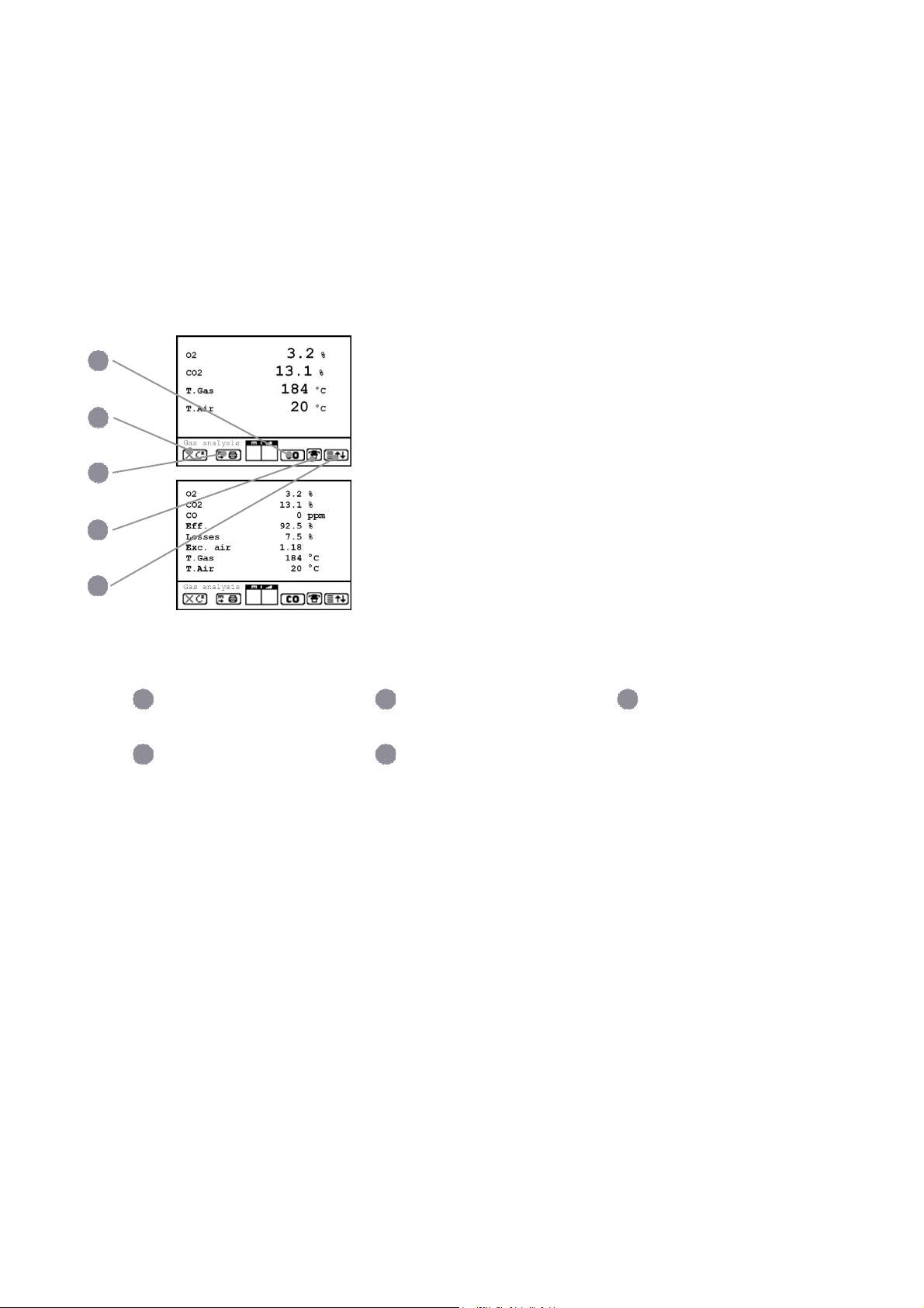
Design of the measurement displays gas analysis 1..3
The following measurement displays are available for the gas analysis procedure:
Measurement display: Gas analysis 1 + 2
Measurement display: Gas analysis 3
1
Switch-off CO-Sensor
key <F3>
4
Symbol cooler ON /OFF
The following functions are available in all 3 measurement displays:
Pressing <F1> enables to switch, from the values display, to a menu point selected before or
on „Standby“ (see chapter Adjustments). Possible menu points are: Soot...Oil trace, Data
processing, View memory, Display values, Fuel type, Efficiency (K), Internal, Adjustments.
Furthermore you can switch back from any random menu point to the values display with
<F1>.
Press <F2> to print out the values simultaneously to their recording in the intermediate
memory.
Press <F3> to cut the CO sensor from the gas path so that it is protected against too high
concentrations.
Pressing <F4> also enables to switch, from the values display, to a menu point selected
before or on „Standby“ (see chapter Adjustments).
2 3
Hotkey key <F1>
Hotkey key <F4>
Store and print values
key <F2>
Page 22
ecom-EN3
Page 23

4.1.1 Adaptation of the displays for gas analysis
Hint
The position of the measured and calculated values (gas analysis sub-menu)
on the display pages is free selectable
For alteration of the existing succession, proceed as follows:
- Press <Enter> / „Display values“ / <Enter> to activate the function
- Select line with cursor keys (Up/Down)
- Select desired parameter with cursor keys (Right/Left)
- Repeat procedure until desired layout is completed
- Press <Enter> to deactivate the function
4.1.2 Positioning the probe, search the core stream
Hint
The correct positioning of the probe in the gas stream is necessary in order to
achieve an impressive measuring result.
To correctly position the probe in the gas stream, proceed as follows:
- Connect the probe hose to the device "connection gas temperature"
- Position the sampling probe in the exhaust channel, so that the thermocouple is fully
1
3
1
4
If an arrow in downwards direction is displayed, it means you move the probe away from the
core stream and the temperature sinks.
surrounded with the gas (see drawing).
Gas stream Protection bow Probe tip
2
3
Position the sampling probe in the exhaust channel
(Position in the hottest gas temperature area).
Observe trend for T.Gas in the measurement display.
As long as the display shows an arrow in upwards
direction, the measured temperature increases, it means
the probe tip moves towards the core stream center.
Core stream search
2
ecom-EN3
Page 23
Page 24

, efficiency, losses, excess air and dew point are calculated values. They can only be
CO
2
calculated if realistic values for the basic parameters like O2 and the temperatures are
available. It must be ascertained that:
O2 < 20,7 % and T.Gas - T.Air > 0 °C
are given. If the gas temperature falls below the dew point (between 25 and 65 °C), so
efficiency will be calculated with condensation gain. In this case a (K) is displayed after
„Efficiency“. Correct measurement values are displayed first after a short delay, necessary
for the gas transport and the build-up of a stable electrochemical reaction to the sensors.
This time period lasts approx. 1 to 1.5 minute. For recording, printout and evaluation, wait
until the values do not change anymore. If deviations higher than 2 ppm still occur by the gas
values, they can be due to unstable pressure conditions in the exhaust channel.
If the measurement values are stable and the results can
be printed out, press the key <Save> to transfer the
values in the intermediate memory (caution: store
separately gas analysis, CO, O2 check and draught
measurements). They will be kept there for a later printout
and, if need be, for a final data record storage.
1
Measurement stored in intermediate memory
4.1.3 Printing measured values
There are two ways to print measurements:
1. Print of the measurements stored in intermediate memory
To print the measured values stored in the previous step, press the <Print> key. The
complete content of the intermediate memory will be printed.
2. Printing the currently displayed values, including storage in intermediate memory
To print the measured values currently displayed, press the key <F2>. At the same time the
measured values are stored and overwrite existing intermediate stored values.
Hint
Use the option "Print the currently displayed values" to adjust the time of optimal
measurement results and to print them immediately.
Page 24
ecom-EN3
Page 25

WARNING
4.1.4 CO-Overload Protection
The CO sensor is protected against overload by the system.
If the limit of 4000 ppm at the CO sensor is exceeded, the internal additional fresh air purging
pump is switched on, which supplies fresh air to the CO sensor.
When the CO overload protection is active, the CO indicator flashes in the status bar of the
measurement screen, and the <Info> status LED changes from "green" to "red".
If the opening for the supply of fresh air to the CO sensor is closed, the
sensor can not be purged with fresh air and will be damaged or destroyed
during overload.
1
Do not lock fresh air opening for fresh air pump!
1
Fresh air opening
If the CO sensor has been purged sufficiently with fresh air (X disappears behind CO) and
the measured values are within the permissible range, the fresh air flushing pump is switched
off.
The CO indicator in the status bar of the measurement screen no longer flashes and the
status LED <Info> changes from "red" to "green".
Hint
The "CO automatic" option can be used to set how the fresh air flushing pump is
switched off after sufficient purging of the CO sensor:
- automatically
- must be triggered manually
To deactivate the CO automatic option, deactivate the
corresponding option in the menu Adjustments \ Internal \ COAutomatic with "No".
To switch off the fresh air flushing pump with the CO automatic
deactivated, press the <F3 <key.
ecom-EN3
Page 25
Page 26

Page 27

4.2 Measurement procedure gas analysis: CO measurement
The gas channel check, called also CO measurement, is used for the technical check of gasfired plants in regards of safety aspects. Hereby the CO concentration in the gas channel is
measured after the flow safety device and calculated on an undiluted value (oxygen rest
content in flue gas = 0%). As the gas conditions after the flow safety device are no more
homogeneous because of the flow in of secondary air and consequently the core stream
measurement can be erratic, the analysis of the exhaust gas is performed along the totality of
the exhaust pipe diameter. A multi-hole probe (optional accessory) is hereby used as
sampling probe.
The calculated value shown on the line „CO 0 %“ corresponds to the measured CO
concentration supposed the oxygen content would amount 0% by the same exhaust gas
volume. It is consequently the undiluted CO content in exhaust gas. If the values indication is
stable, press <Record> to store the result in the intermediate memory. If a printout of the
values should occur simultaneously to the recording in the intermediate memory press <F2>
(the complete content of the intermediate memory will be printed out).
1
Measurement stored in intermediate memory
4.3 Measurement procedure gas analysis: O2 Check
This measurement is performed by room-independent plants like gross calorific value plants.
It is determined if exhaust gas flows into the combustion air (O2 content drops down / CO
content can be present) and herewith influence on the combustion quality. For this analysis,
a special multi-hole probe (optional accessory) should be used. If the value indicated is
stable, press <Save> to store the value in the intermediate memory. If a printout of the values
should occur simultaneously to the recording in the intermediate memory, press <F2> (the
complete content of the intermediate memory will be printed out).
Measurement display: O2 Check
ecom-EN3
Page 27
Page 28
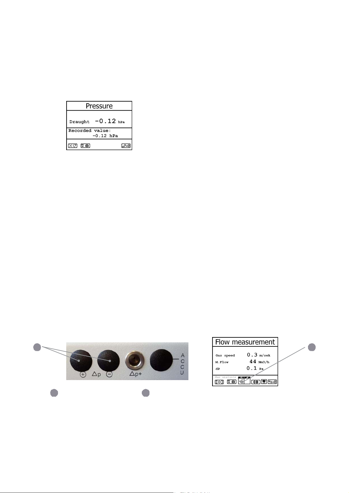
4.4 Measurement procedure gas analysis: Draught measurement
1
A trend indication for the draught conditions in the exhaust channel can already be viewed
during the gas analysis. Nevertheless the value for the chimney draught will not be stored
together with the gas values while pressing <Save> because the differential pressure sensor
tends to drifts because of its sensibility. For an exact measurement, it is consequently
advised to re-calibrate this sensor just before sampling and documenting the value.
The display shows the current value as well as the recommendation to re-set the zero point
of the sensor. Disconnect the draught hose from the instrument for a short moment and
press <F4>. The sensor is herewith re-calibrated.
Re-connect the draught tubing. The display shows the exact measurement value which can
be stored while pressing <Record> and added to those results previous stored in the
intermediate memory. The stored value is shown on the display. Press <ESC> to exit the
draught measurement menu.
4.5 Measurement procedure gas analysis: Flow measurement Pitot tube (option)
This measurement can be done with a Pitot tube. At first the pitot factor of the pitot tube must
be entered („Adjustments“ / „Internal“ / „Pitot factor“). After connecting the Pitot tube to the
instrument, the zero point of the sensor can be set with <F4>. With <F1> the cross section of
the flow channel can be entered (needed for calculation of the flow rate). After the Pitot tube
is positioned in the flow channel, the display shows the speed (m/s) and the flow rate
3
/h). If the value indicated is stable, press <Save> to store the value in the intermediate
(Nm
memory. If a printout of the values should occur simultaneously to the recording in the
intermediate memory, press <F2> (the complete content of the intermediate memory will be
printed out).
2
1
Connections for Pitot tube Measurement stored
2
in intermediate
memory
Page 28
ecom-EN3
Page 29
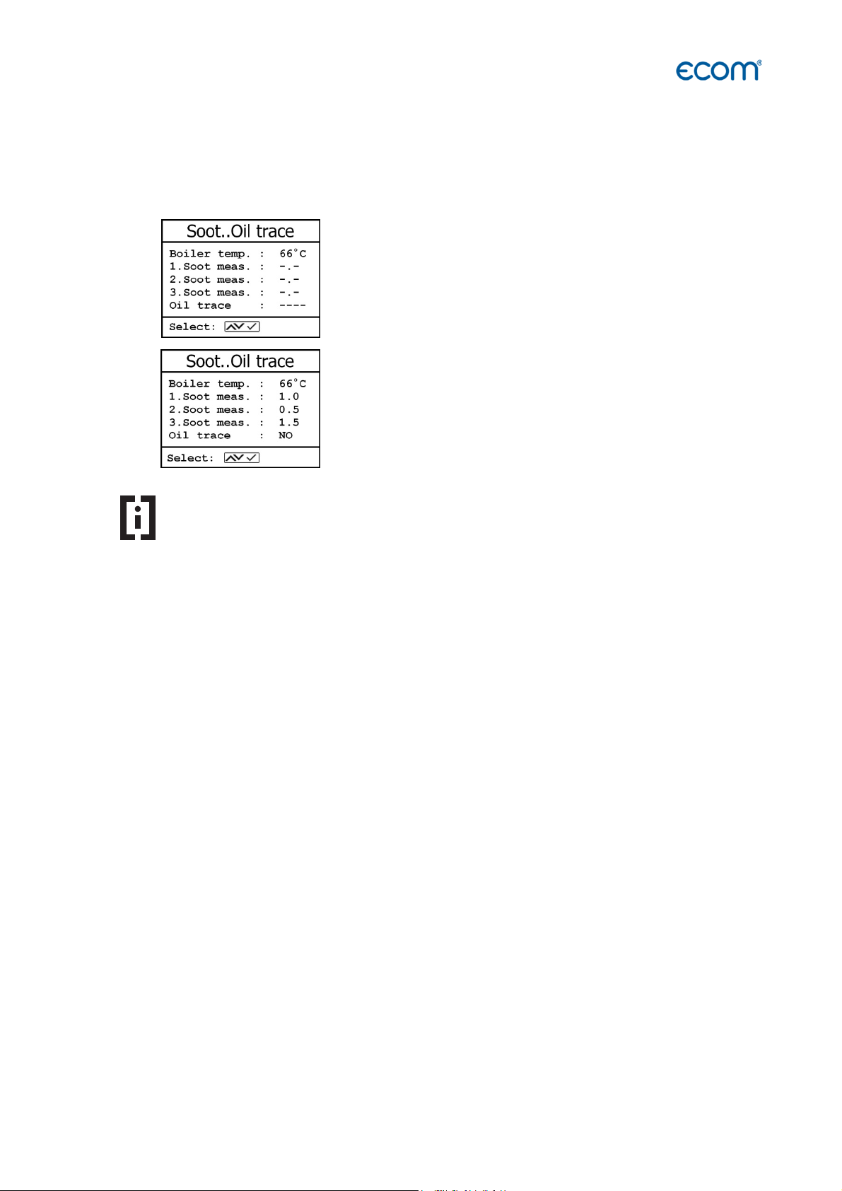
4.6 Measurement procedure gas analysis: Soot...Oil trace
The sub-menu "Soot...Oil trace" enables the input of measured results for boiler temperature,
soot dots and oil trace. Select the desired line on the display and activate the input with
<Enter>. The input for boiler temperature can be made one with help of the instrument
keyboard. Press <Enter> to store the value in the data record of the measurement.
Hint
To use the automatically soot measurement, you have to select the fuel type
oil!
4.6.1 Soot measurement
The soot dot measurement is to be performed with the optional heated pistol grip probe
which heating function prevents the filter paper to become wet because of the humidity
issued by the combustion condensate. The filter paper slot is hereby heated up to approx.
70 °C. Switch hereto the probe heating of the pistol grip probe while selecting „Adjustments /
Internal / Probe heating / <F1>“.
Insert a filter paper in the paper slot. Select the line „1st Soot meas.“. Press <Enter> to start
the measurement. The display shows the volume to be sucked and the pump starts sampling.
If the soot dot analysis are made with a manual pump the sucking procedure can be
interrupted while pressing <F4> (result value can immediately be entered).
Once 1,63 litre has been sucked in, the instrument will instruct to input the opacity degree.
Release the filter paper from the probe slot. Compare the greyness with the opacity scale.
Input the result using the numerical keys and press <Enter>. Repeat this procedure until all 3
soot dot analysis are completed. The mean value will be calculated and automatically stored.
4.6.2 Oil trace
The result of the oil trace check will be documented as follows:
- Place cursor on line "Oil trace"
- Consign the result with <Enter> ("No", "Yes" or "- - - ")
Once all inputs have been entered, press <ESC> to exit the menu. The measurement is now
complete.
ecom-EN3
Page 29
Page 30

4.8 Measurement procedure gas analysis: Data processing
To call up plant data already recorded or to create a new file, the following possibilities are available:
4.8.1 Create new
(is automatically selected by first use of a MM card)
To create a new file, a numerical number should be assigned. Select „Create new“ and
confirm with <Enter>. Input a random number (max. 16 figures) using the keyboard:
- use the cursor keys <Up/Down/Right/Left> to select
the figure (selected figure outlined by a black background)
- press <Enter> to accept the figure (press <F2> to delete
the last figure if needed)
- repeat this procedure until the desired number is complete.
Example: "25.09.2009"
Tip: We suggest a date-related input to easily find the data
record later on via the search function.
After confirming with <F1> it is possible to enter a text via the keyboard (max. 6 lines
with 20 characters each) which is printed out and can be used for data processing
purposes. Proceed as follows:
- select text line 1 using the cursor keys <Up/Down> and confirm with
<Enter>
- select with <F3> the keyboard mode (4 keyboard modes are available)
- select with the cursor keys <Up/Down/Right/Left> the desired
character (selected character outlined by a black background)
- press <Enter> to accept the character
(press <F2> to delete the last character)
- repeat this procedure until the desired text is complete.
- proceed as follows to correct a character:
- press <F4> to interrupt the character selection
- use the cursor keys <Right/Left> to select the character requiring correction
- activate with <F4> the character selection and correct character
- return with <F1> to character selection and call up next line for
process
The input is closed with <ESC> and the next available data record is activated. Press
<ESC> to return to the gas analysis menu.
Memory number: For check of the plant already stored in the instrument, the selection
upon record number is most appropriate.
Page 30
ecom-EN3
Page 31
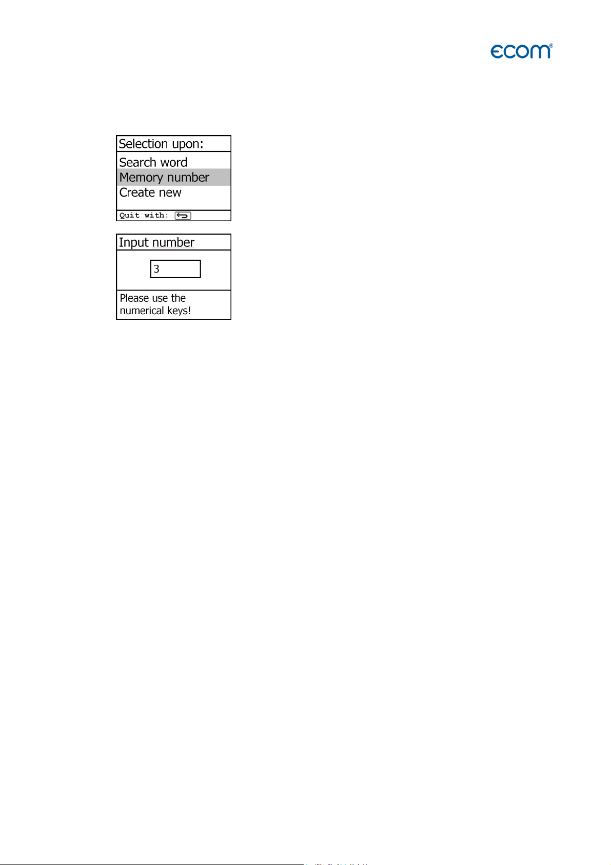
4.8.2 Memory number
For check of the plant already stored in the instrument, the selection upon record number is
most appropriate.
Select „Memory number“ and confirm with <Enter>. Input a
random data memory number:
Example: "3" for data record number 3
Press <Enter> once the input is completed to call up said data memory number. The cursor
keys <Up/Down> enable the check of the record numbers.
Press <F1> to select the first memory number.
Press <F2> to select the last memory number.
Press <F4> to delete the content of the selected memory number.
Press the <Enter> to select the currently displayed memory number and store the following
measurements under this memory number.
Finally press <ESC> to start the gas analysis.
ecom-EN3
Page 31
Page 32

4.8.3 Search word
Measurement available
If the plant code is known, it is possible to find the plant data stored with help of a search
machine. Select hereto "Search word" and confirm with <Enter>. Using the software
keyboard, input at least 3 connected figures of the plant
After input completion, press <F1> to start the search. All files matching this code will be
filtered. The resulting selection can be scrolled using the cursor keys:
- <F1> for selection start
- <F2> for selection end
1
Example: "25.09" for plant code 25.09.2009
Once found, activate the desired data record with <Enter>. The last measurement on this
plant can be viewed pressing <Enter> / „View memory“ / <Enter>.
All measured and calculated values can be called up on 5 display pages, using the cursor
keys to step thru.
Press <ESC> to escape the previous measurement data and the recording of the current data
can start.
Page 32
ecom-EN3
Page 33
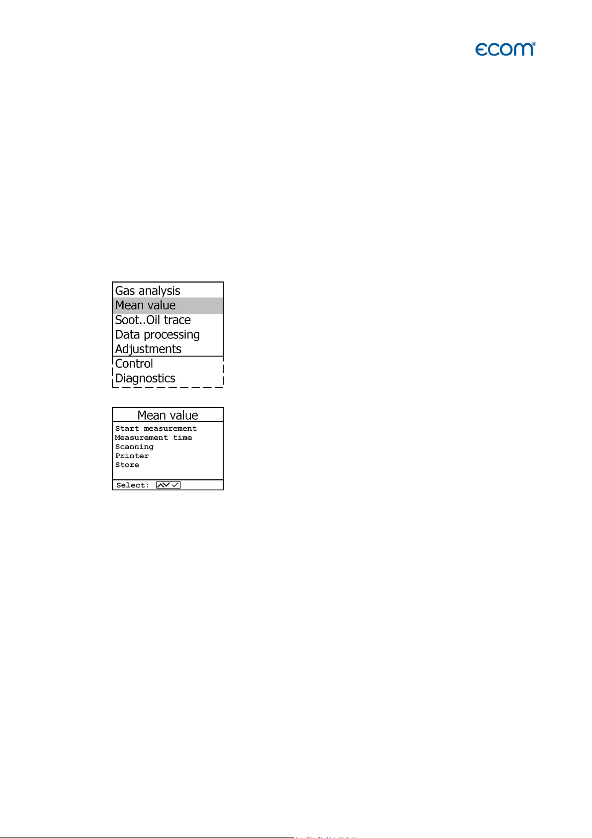
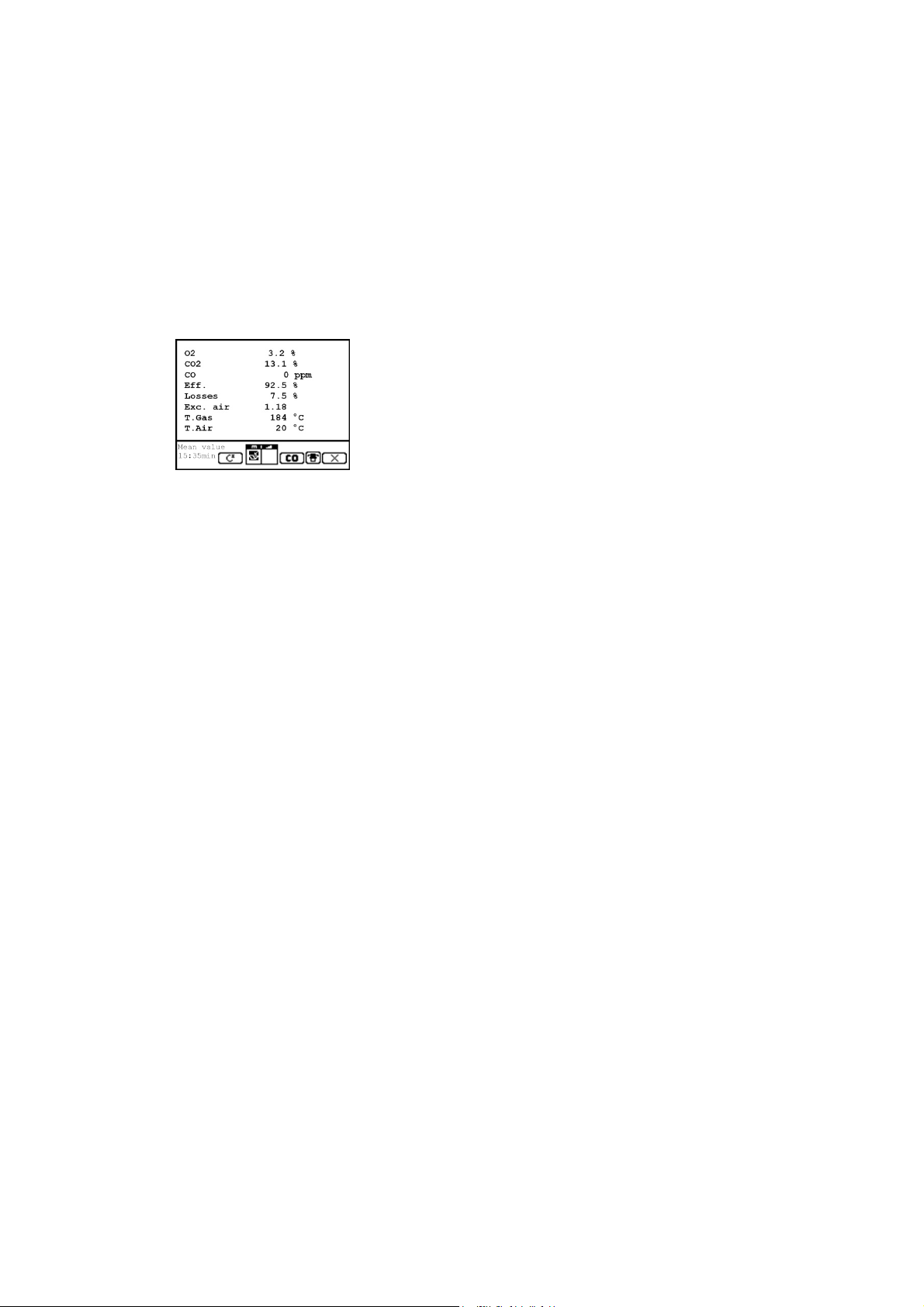
5. Measurement procedure mean values
By mean value measurement function, measurements can be sampled within an adjustable
time frame and mean values can be calculated. Should the several measurement values or
the mean value result be stored a storage place has to be selected as described in chapter 7.
If the function “Store” is activated, based on this storage place all measurements will be
written consecutively on the next storage places. If the function “Store” is not activated, the
mean value result can be stored on MMC with <Print> / „Memory -> M.
Once the fresh air calibration is completed, select the menu point „Mean values“. Before
starting, the parameters „Measurement time“, „Scanning“, „Printer“ and „Record“ should be
checked or modified if need be. The meaning is respectively:
- Measurement time = Time frame during which the mean values will be sampled
- Scanning = Time interval between the measurements considered for mean value
calculation
- Printer = Documentation of measurements serving to the mean value calculation
- Store = All measurements for mean value calculation will be stored
„Measurement time“ and „Scanning“ can be adjusted as follows:
- select menu point and confirm with <Enter>
- set the desired time using the numerical keys:
0.01 = 1 sec = minimal value
59.59 = 59 min : 59 sec = maximal value
- confirm with <Enter>
The settings for „Printer“ can be changed as follows:
- select menu point and confirm with <Enter>
- select desired adjustment with cursor keys
- confirm with <Enter>
The setting for „Store“ can be changed as follows:
- select menu point and confirm with <Enter>
- activate memory function with <F1> or
- deactivate it with <F4>
ecom-EN3
Page 33
Page 34
By ‘Start measurement’ / <Enter> the evaluation of the measurement values will be started.
On the display the actual mean values will be shown (will be updated with new measurement
values / switch to the actual values with cursor keys <up/down>). It is possible to scroll
through the values with the cursor keys <right/left>. With <F2> you can interrupt and with
<F4> stop the measurement.
After finishing the measurement time a protocol of the results with all mean values can be
printed (key <Print>).
Page 34
ecom-EN3
Page 35
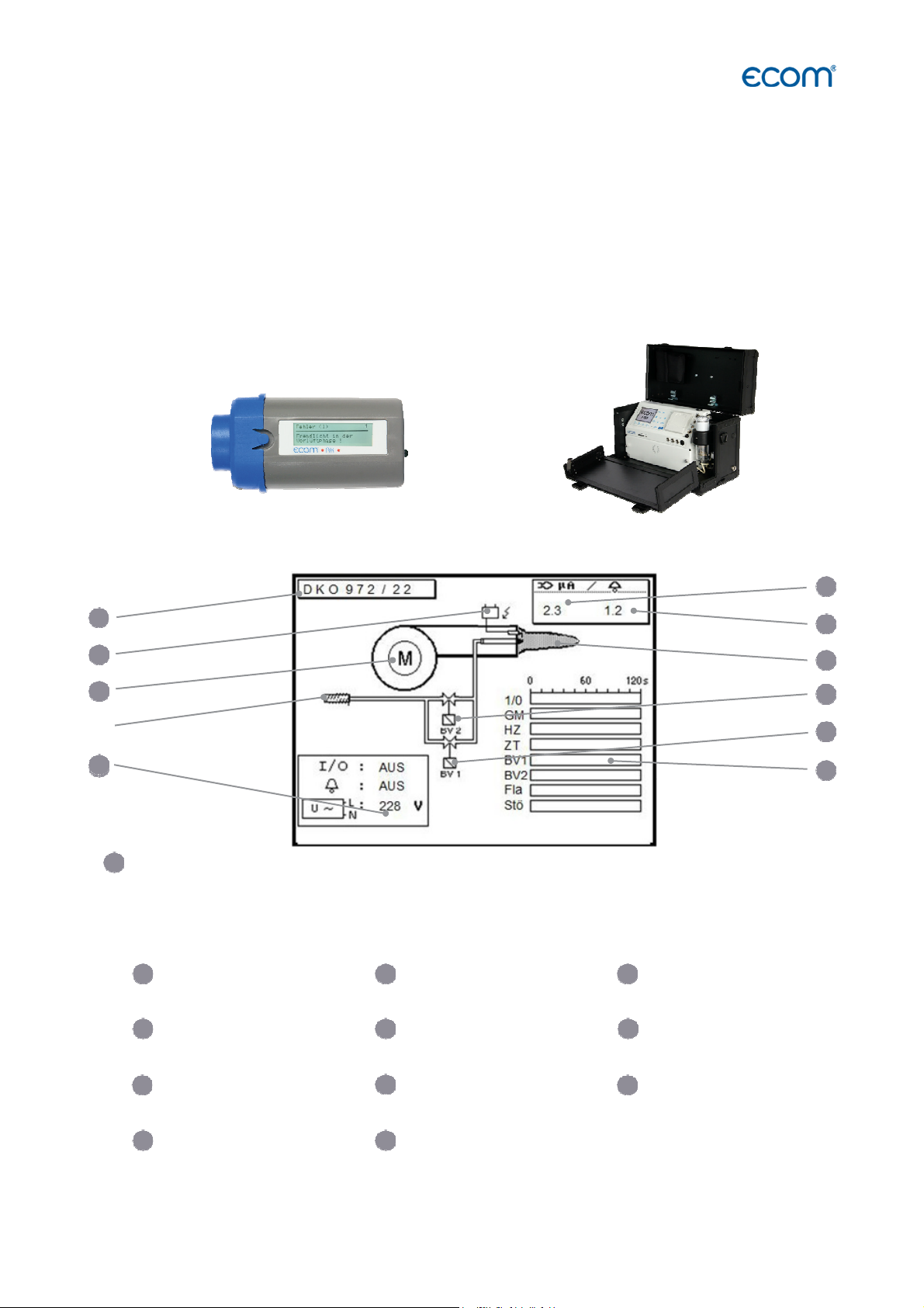
1/0 = Continuous phase
RM = Fan motor
OV
= Oil preheater
RZ = Ignition
BV1 = Valve 1st stage
BV2 = Valve 2st stage
FL = Flame identified
Err = Disturbance
ecom
-
EN3 ecom
-AK
3
11
4
7
10
5
11
6. Measurement procedure Diagnostics
6.1 Fault diagnostic
The ecom-EN3 is able to receive and to process information provided via cable transfer by
the ecom-AK (read-out head for digital firing automates).
Out of the main menu, select the sub-menu "Fault diagnostic" and confirm with <Enter>.
The ecom-EN3 tries to establish a connection with the ecom-AK (display message:
„Search in process“).
By successful attempt, the current burner operation stand is displayed as a graphic on the
display. The operation stand can be recorded (max. 120 sec). Press <Enter> to initiate a new
recording (reset).
1
2
4
Recording of operation stand (max. 120 sec.):
6
7
8
9
10
ecom-EN3
Reset = Starts a new recording (confirm with <Enter>)
1
Model name Ignition is active Engine on
Oil heater/
2 3
5 6
Operation voltage
Air pressure monitor is on
Flame signal min Flame identified Valve 2 is on
8
9
11
Valve 1 is on
Recording of operation stand
(max. 120 sec.)
Flame signal is
Page 35
Page 36

Use the cursor keys (Up/Down) to call up further data of the firing automate. On the 2nd display page
the current error and the number of burner starts are displayed.
1
2
1
Current error Number of burner starts at a
4
Error statistics (number of
errors)
2
total resp. since reset of firing
automate
5
Monitoring times of firing automate
Last 2 errors (Satronic) Last 5
errors (Siemens) (Scroll errors
using <Right/Left>)
The 3rd display lists information about error history (type
3
and volume of information depending on firing automat).
4
5
The 4th display page lists information about the
monitoring times (type and volume of information
depending on firing automate).
Page 36
ecom-EN3
Page 37

6.2 delta-T Measurement
With the ecom-EN3 a difference temperature measurement is possible. For measurements at
pipes (e.g. water-in and water-out of heating systems), special temperature sensors are
needed, available from your authorized ecom agency. Out of the main menu point
"Diagnostics" select the sub-menu "dT measurement" and confirm with <Enter>.
The instrument indicates the temperature T1 (sensor at connection „Gas temperature“), the
temperature T2 (sensor at connection „Air temperature“) and the difference between both
temperatures (T1 - T2). Press <Save> to store the result in the intermediate memory. A
printout can be started with <Print>.
1
Measurement stored in intermediate memory
ecom-EN3
Page 37
Page 38

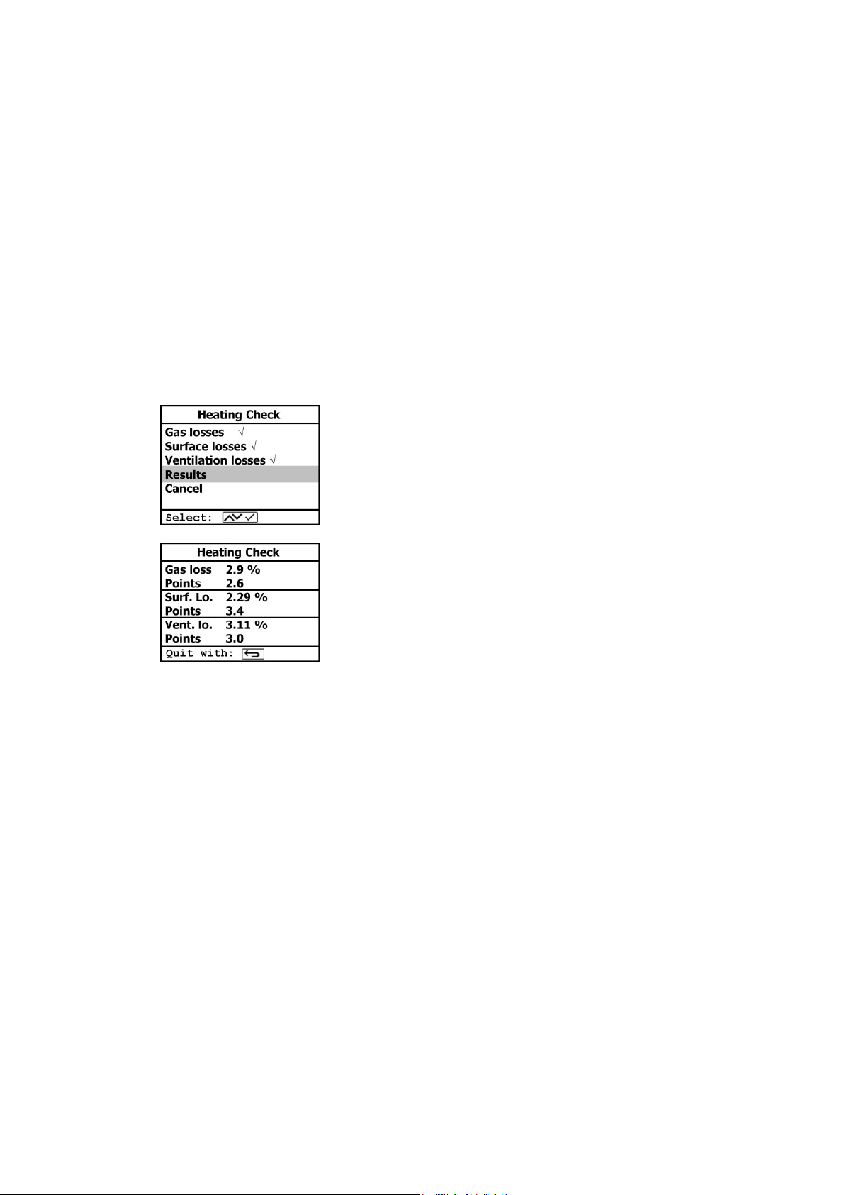
6.3 Heating Check (option)
The heating check is a simple, expressive process to evaluate a complete heating plant (heat
production, distribution and transfer) from the energetic point of view. Hereby the single plant
components get inspected by the heating engineer in a combination of measurements and
visual assessment and valued in regards of their energetic quality acc. to a negative point
system of maximum 100 points. The higher the score, the farer the current plant is away from
the desirable energetic stand and the higher the energy saving potential would be if
modernization measures are conducted. In combination with the special probes required
hereto, the ecom-EN3 is able to perform the measurement of the heating check parameters:
gas losses, ventilation losses and surface losses. Out of the main menu point "Diagnostics",
select the sub-menu "Heating Check" and confirm with <Enter>.
The gas losses measurement is to be performed with the
instrument´s sampling probe in the gas core stream after
menu call up. Once the measurement is recorded with
<Save> (disk symbol) the conversion of the measurement
results in negative points is available under the menu
point „Results“.
The surface losses measurement is performed by a temperature sensor specific for surfaces.
The temperature difference between boiler surface and room temperature (air temperature
sensor) is determined and the percentage loss is calculated. Once the menu point is called
up, the boiler performance must be inputted. To easy the measurement width, depth and
height of the boiler can also be entered (dimensions will be memorized for surface
calculation). Please proceed as follows:
- activate respective input window with <Enter>
- inputs values using the keys numerical function
- confirm input with <Enter> or:
- adjust values using the cursor keys <Right/Left>
Page 38
ecom-EN3
Page 39

If no boiler dimensions are inputted, press <F1> (Start) to activate the measurement
recording. Here the dimensions for all surfaces must be inputted.
Press <F3> (Start + ->) to start the real measurement. Proceed as follows:
- select surface (boiler side) to be measured with <F1> or <F2>
- position surface sensor record temperature difference with <Memory>
- up to 10 values can be recorded per surface out of which a mean value will be
calculated automatically
- if need be, cancel measurements with <F4>
- repeat this procedure for each surface
Flow probe
ecom-EN3
Once all surface temperatures have been determined, quit the menu with <ESC>. The
surface losses get automatically calculated. The value conversion in negative points is
available in the menu point „Results“.
The ventilation loss measurement is performed by a flow probe 30 sec. after burner switchoff. This measurement can be performed at the earliest 5 min. after instrument´s switch-on as
the pressure sensor requires this period of time for stabilization. Once the menu is called up,
the values for air pressure, external temperature, boiler performance and exhaust gas pipe
diameter must be inputted. Hereto proceed as follows:
- open respective window with <Enter>
- input figures using numerical function of keys
- confirm input with <Enter> or:
- adjust values using the cursor keys <Right/Left>
Page 39
Page 40
Press <F1> (Start) prior to going thru the following steps to start the measurement:
- release tubing of the flow probe
- wait for zeroing of pressure sensor
- re-connect tubing of the flow probe
- position flow probe into exhaust gas pipe
(observe mark for flow direction)
- switch off burner and simultaneously press <F1> or:
- press <F2> to activate timer (5 sec.) and switch off burner by beep
- after approx. 30 sec. the measurement value converted in negative points is
available
An overview of the measurements is available under „Results“. Press <Print> to print them
out.
Page 40
ecom-EN3
Page 41

6.4 4 Pa Measurement (option)
The simultaneous operation of room-dependent firing place and air evacuation system can
lead to dangerous low pressure conditions. With the ecom-EN3 it is possible to check the low
pressure limit value of 4 Pa and to document in a diagram the time course of the low
pressure value. Once the menu point is called up, the measurement is to be performed as
follows:
- connect capillary hose for room where burner is installed to „-“
- connect capillary hose for reference place (staircase or outside air to „+“
- operate firing and evacuation systems with maximal performance
- open window resp. connection door to burner room and check the correct
evacuation of the exhaust gases
- zero pressure sensor with <F4>
- position capillary hose for reference location
- start record pressure value course with <F1> (Start) (an acoustical signal is issued
every 30 sec. which can be deactivated / re-activated pressing <F2>)
- record pressure by opened window resp. connection door
- close window resp. connection door after approx. 30 sec. and check low pressure
- after approx. 30 sec. open window resp. connection door and check zero point
- close window resp. connection after approx. 30 sec. and check low pressure
- after approx. 30 sec. re-open window or connection door and check zero point
- after approx. 30 sec. close window resp. connection door and check low pressure
Once the measurement time is completed, the diagram can be viewed on the display (use
<F3> to emphasize illustration 1x, 2x, 4x, 8x times or A for automatic). Start a printout if
needed with <Print>.
ecom-EN3
Page 41
Page 42
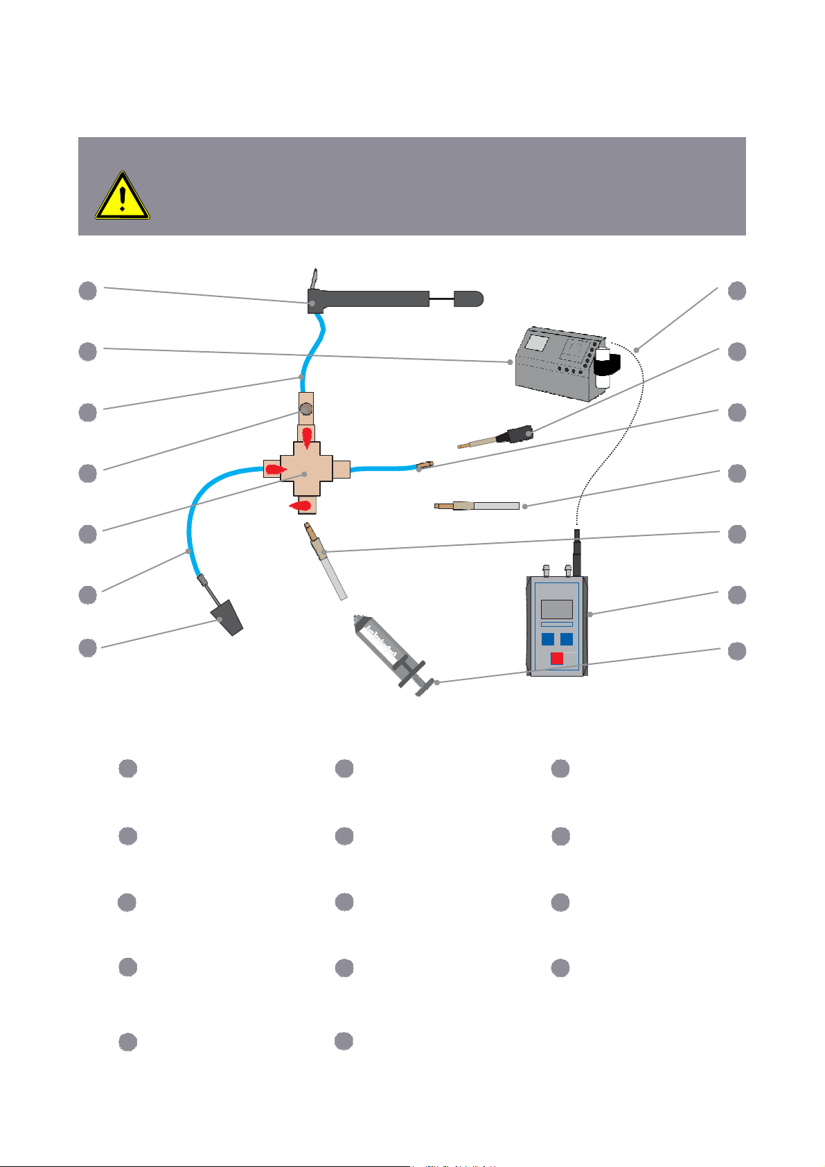
6.5 Pressure Tests (option)
WARNING
1.
2.
Use only air or inert gas for check!
Respect the „Technical Rules for Gas installations“!
10 11 12
10 11 12
7
14
13
14
1
2
3
4
5
6
1
Air pump
4
Safety valve
7
Conic test stopple, One-pipe
counter cap or High-pressure
test stopple
Connection hose
(ecom-EN3 / UNO Cross piece)
ecom-UNO (only for Loading
and Tightness Test)
2
ecom-EN3
5
Cross piece
8
Electrical connection
ecom-EN3 / UNO
Connection ecom-UNO
(+)
3
Connection hose
(Pump - Cross piece)
6
Connection hose (Gas
system - Cross piece)
9
Connection ecomEN3 (delta p-)
Connection Squirt or Soot
pump
Syringe
8
9
13
Page 42
ecom-EN3
Page 43

The following measurement procedures are available in the Pressure tests menu:
- Pressure Test
- Loading Test
- Tightness Test
- Usage property
In the menu Pressure Tests / Setup adjustments can be made for each measurement
procedure.
6.5.1 Pressure Test
The “Pressure Test” up to 100 hPa is deposited as a measurement routine in the ecom-EN3.
Proceed as follows:
1. Close the conduit with a suitable adapter (test stopple, high-pressure
stopple or one-pipe counter cap).
2. Connect the components as described before.
3. Scroll with cursor keys <Up/Down> to the menu “Pressure Test”. Activate with
<Enter>.
4. Create the pre-adjusted test pressure (max. 100 hPa) with the air pump.
5. Interrupt the connection to the air pump (switch-off the ball valve) and start “Pressure
Test” with <Enter>.
6. Wait for stabilization time (the measurement will start automatically).
7. Once the measurement time is over, the result is displayed and can be printed by
pressing <Print>.
8. If the menu “Pressure Test” is selected again, so the result can be called
up with <F4> (as long as the ecom-EN3 is on) or a new measurement
can be started with <F1>.
The following adjustments can be made in the menu Pressure Tests / Setup for the procedure
"Pressure Test":
Parameter Meaning Adjustment Factory setting
Stabilization time
Measurement time
ecom-EN3
1 … 120 min 1 min
1 … 120 min 5 min
Page 43
Page 44

6.5.2 Loading Test
The „Loading Test“ acc. to DVGW – TRGI Process Instructions G 600 by pipes (operation
pressure up to 100 hPa) is deposited as a measurement routine in the ecom-EN3. Proceed as
follows:
1. Connect the ecom-UNO to the connection AUX of the ecom-EN3.
2. Close the conduit with a suitable adapter (test stopple, high-pressure
stopple or one-pipe counter cap).
3. Connect the components as described before.
4. Scroll with cursor keys <Up/Down> to the menu „Loading Test“. Activate with
<Enter>.
5. Create the pre-adjusted test pressure with the air pump (the unit beeps as soon as
the pressure level is achieved).
6. Interrupt the connection to the air pump (switch-off the ball valve).
7. Wait for stabilization time (if the pressure remains in the range „test pressure +/10% during stabilization time, so the measurement will start).
8. Once the measurement time is over, the result is displayed and can be printed by
pressing <Print>.
9. If the menu „Loading Test“ is selected again, so the result can be called up with
<F4> (as long as the ecom-EN3 is on) or a new measurement can be started with
<F1>.
The following adjustments can be made in the menu Pressure Tests / Setup for the procedure
"Loading Test":
Parameter Meaning Adjustment Factory setting
Stabilization time
Measurement time
Test pressure
1 … 240 min 1 min
10 … 240 min 10 min
90 … 1200 hPa 1000 hPa
Page 44
ecom-EN3
Page 45
6.5.3 Tightness Test
The „Tightness Test“ acc. to DVGW – TRGI Process Instructions G 600 by pipes (operation
pressure up to 100 hPa) is deposited as a measurement routine in the ecom-EN3. Proceed as
follows:
1. Connect the ecom-UNO to the connection AUX of the ecom-EN3.
2. Close the conduit with a suitable adapter (test stopple, high-pressure
stopple or one-pipe counter cap).
3. Connect the components as described before.
4. Scroll with cursor keys <Up/Down> to the menu „Tightness Test“. Activate
with <Enter>.
5. Create the pre-adjusted test pressure with the air pump
(the unit beeps as soon as the pressure level is achieved).
6. Interrupt the connection to the air pump (switch-off the ball valve).
7. Wait for stabilization time (if the pressure remains in the range „test
pressure +/- 10% during stabilization time, so the measurement will start).
8. Once the measurement time is over, the result is displayed and can be
printed by pressing <Print>.
9. If the menu „Tightness Test“ is selected again, so the result can be called up
with <F4> (as long as the ecom-EN3 is on) or a new measurement can be
started with <F1>.
The following adjustments can be made in the menu Pressure Tests / Setup for the procedure
"Tightness Test":
Parameter Meaning Adjustment Factory setting
Stabilization time
Measurement time
Test pressure
1 … 120 min 1 min
10 … 120 min 10 min
90 … 160 hPa 150 hPa
ecom-EN3
Page 45
Page 46
6.5.4 Usage property
The „Usage property“ acc. to DVGW – TRGI Process form G 624 by conduits is memorised as
a measurement routine by the ecom-EN3.
The calculation of the leak rate happens automatically ac-cording to the following equation
and corresponds herewith to the procedure of the DVGW-TRGI Process Form G 624:
VB = V/TM * ((PA + P1)/(PA + P2)-1) * PB/P1 * f
Parameter Meaning
VB Gas leak volume in operation state (l/h)
V Pipe content in litres
TM Measurement duration in hours
PA Barometer stand in hPa
P1 Test pressure at meas. beginning in hPa
P2 Test pressure at measurement end in hPa
PB Maximal gas operation pressure in hPa
f Factor for consideration of gas type
Proceed as follows:
1. Close the conduit with a suitable adapter (test stopple, high-pressure
stopple or one-pipe counter cap).
2. Connect the components as described before.
3. Scroll with cursor keys <Up/Down> to the menu „Usage property“. Activate with
<Enter>.
4. Choose the gas type (f) with cursor keys <Up/Down> and confirm with <Enter>.
The following gas types are recorded with their respective factors:
Gas
Natural Gas
Air
Town Gas
Propane
Butane
Hydrogen
5. Type in the maximal operation pressure (PB) with the instrument keyboard
and confirm with <Enter>.
Page 46
ecom-EN3
Page 47

6. The pipe volume (V) is needed for the calculation of the leak rate. The ecomEN3 offers two possibilities:
a. Type in pipe volume (V):
- Choose NO at the inquiry „Calculate Volume automatically ?“
- Type in pipe volume (V) with the instrument keyboard and confirm with <Enter>.
b. Calculate pipe volume automatically (V):
- Choose YES at the inquiry „Calculate Volume automatically ?“.
- Connect the squirt or soot pump as described before.
- Open ball valve and wait until the pressure is stabilized.
- Choose syringe or soot pump with the cursor keys <right/left>.
- Start volume calculation with <Enter>.
- Sample the test volume with squirt or soot pump. The decrease of pressure
must be min. 2 hPa (otherwise operate squirt or soot pump several times).
- Close ball valve and confirm with <Enter>.
- Choose number of strokes with the cursor keys < right/left > and confirm with
<Enter>.
7. Create the pre-adjusted test pressure with the air pump (the unit beeps as soon as
the pressure level is achieved).
8. Interrupt the connection to the air pump (switch-off the ball valve).
9. Wait for stabilization time (if the pressure remains in the range „test pressure +/10% during stabilization time, so the measurement will start).
10. Once the measurement time is over, the result is displayed and can be printed by
pressing <Print>.
11. If the menu „Usage property“ is selected again, so the result can be called up
with <F4> (as long as the ecom-EN3 is on) or a new measurement can be started
with <F1>.
The following adjustments can be made in the menu Pressure Tests / Setup for the procedure
"Usage Property":
Parameter Meaning Adjustment Factory setting
Stabilization time
Measurement time
Test pressure
Max. operation pressure
ecom-EN3
1 … 270 min 1 min
10 … 240 min 10 min
20 … 160 hPa 50 hPa
10 … 100 hPa 23 hPa
Page 47
Page 48
7. After Measurement
After the measurements have been completed, the following things have to be observed
BEFORE turning the instrument off.
7.1 Save measurement, print measurement
Hint
Once the gas analysis is completed and a memory place is chosen before, transfer
the values recorded in the intermediate memory on the MM card, otherwise they
would get lost by switch-off of the instrument!
proceed as follows
Hint
The functions „View memory“, „Memory -> M“ and „Input text“ can also be
selected out of the measurement mode with <Enter>.
To store measured values permanently on the MM card,
Press <Print> (printer symbol) to enter the printing menu.
The sampled data can be checked one more time („View
memory“, <Enter> and scroll with the cursor keys). The
cursor keys can be used to scroll through the
measurement screens.
By selecting the "Insert text" menu item, the plant
identifier can be entered or changed.
See chapter "Measurement procedure gas analysis: Data
processing" for more information.
All data correct? Then press „Memory -> M“ and <Enter>
to transfer them in the internal memory or on the MM card
("Symbol memory" is shown in black in the measurement
mode). The inputted text is taken over into the data record
only by transfer on MM card.
Select („Start printout“ and <Enter>) to print out the data.
Press <ESC> to turn back to the gas analysis mode.
To access these functions directly via the measurement screen,
press the <Enter> key.
Page 48
ecom-EN3
Page 49

7.2 To-Dos before switching off
Before switching off the device, the following points must be observed:
- Correct stowage of the probe
- Checking the fine dust filters
- Emptying the water trap
WARNING The hot probe can cause damage to the instrument or to the transport
system.
Let the probe cool down before stowing it!
WARNING Highly contaminated filters can affect the volumetric flow in the gas path and
therefore the measurement
Check the condition of the particle filter.
Replace the particle filter when the contamination of the filter
is equivalent to a soot number of approx. 2 - 3.
WARNING For instruments without automatic condensate emptying, condensation
water from the condensation tank can flow into the gas path inside the
instrument and damage the sensors.
Empty the condensate trap before transporting the
instrument.
(Only for devices WITHOUT automatic condensate emptying.)
Emptying the water trap as follows:
1. Pull the drain hose
2. Drain the condensate
3. Re-attach the drain hose
1 2 3
ecom-EN3
Page 49
Page 50
3
8. Control
The electrochemical sensors for gas analysis are submitted to a wearing process and do
age. They alter their output values along the time depending on the gas concentration, the
exposure time and the soiling grade of the sampled gas.
The program monitors the sensors and corrects drifts. But if the drifts and the correlated
measurement errors increase, an error message is displayed. In this case the corresponding
sensor must be changed by an authorized service centre.
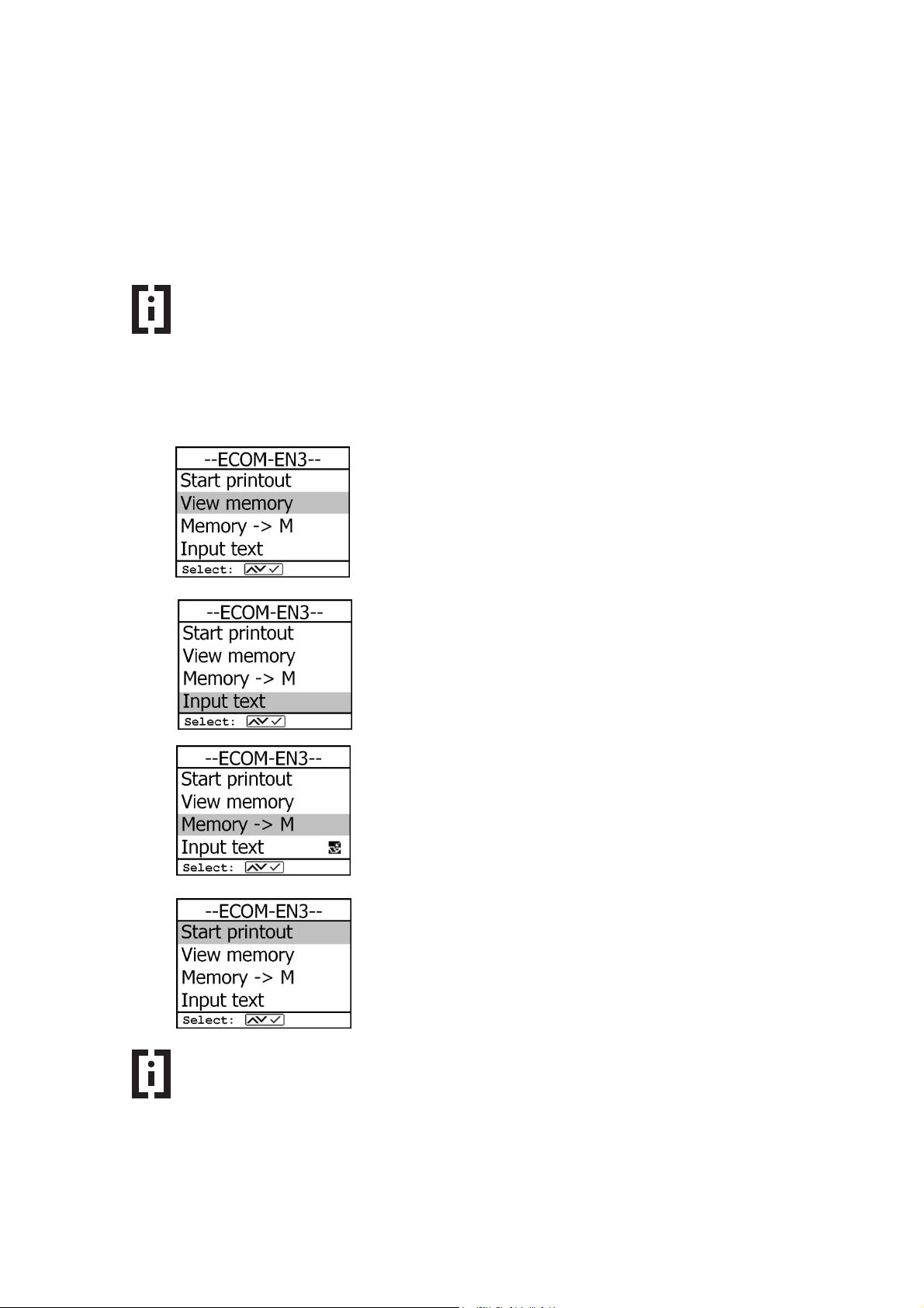
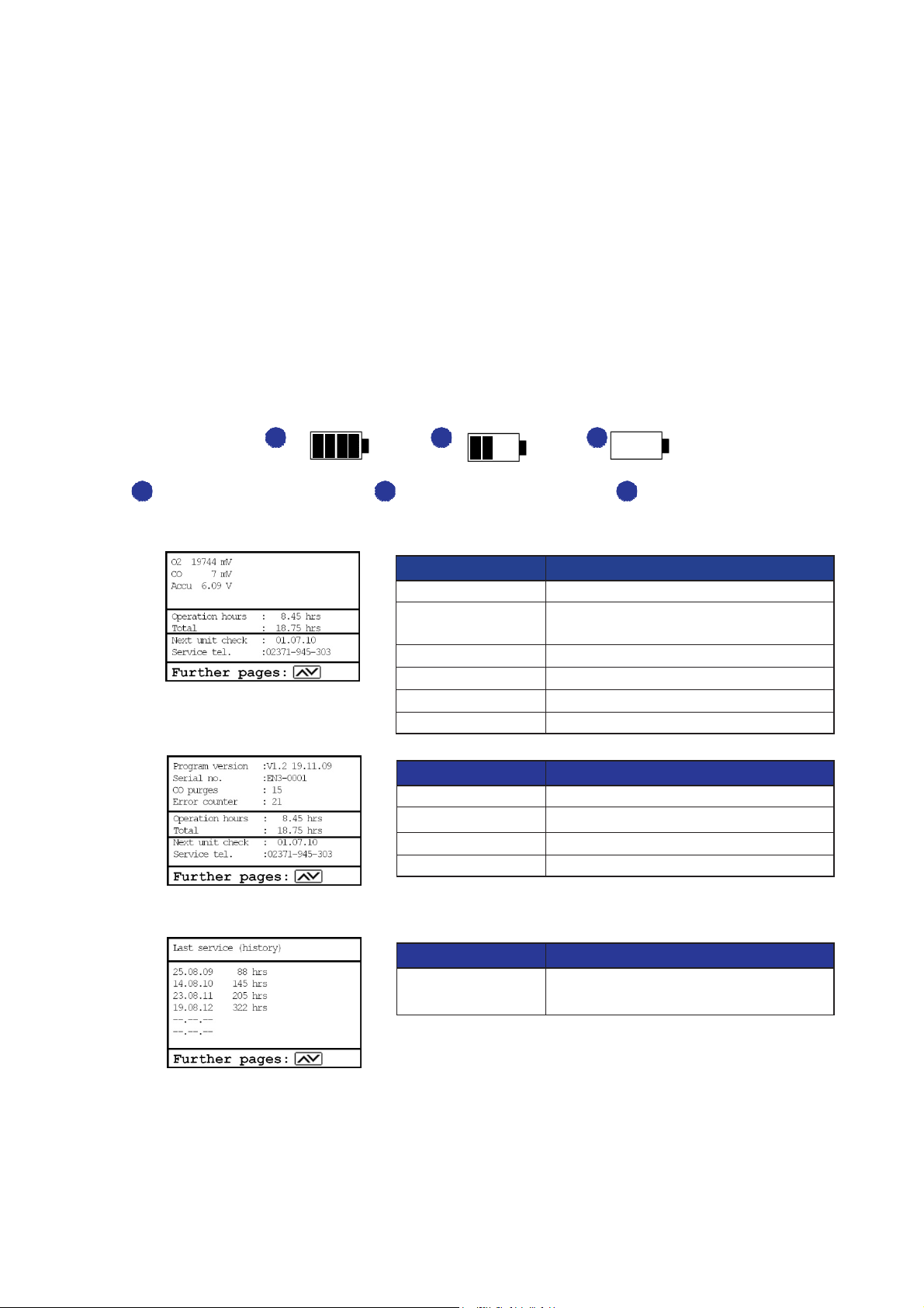
The control menu informs about the current status values for the sensors. Further
information is also consigned on 3 display pages (use cursor keys to scroll)
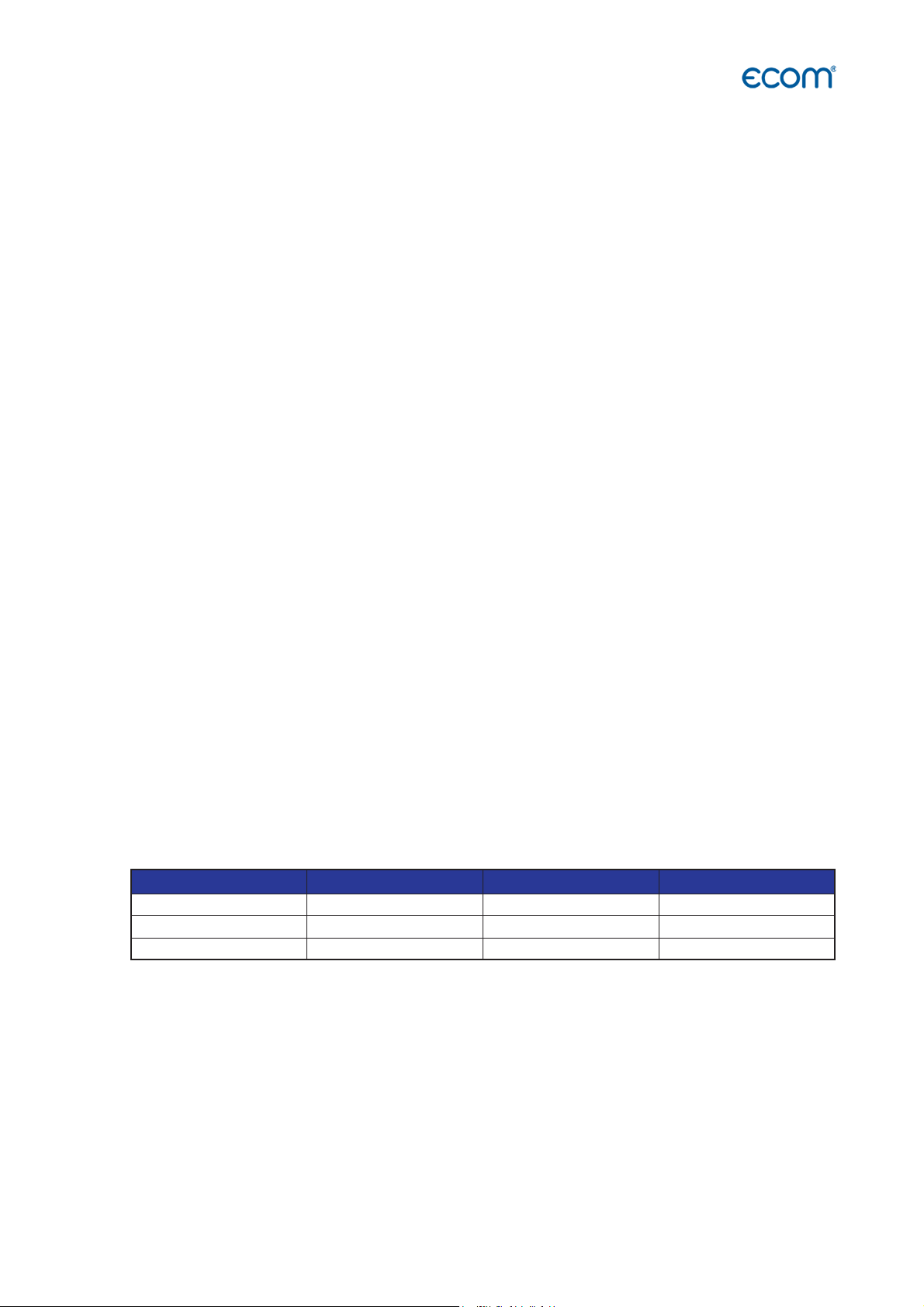
The following status values are available:
1
- battery voltage (charging status); is displayed as a symbol in all menus:
1 2
Full charge Half charge Empty
2
3
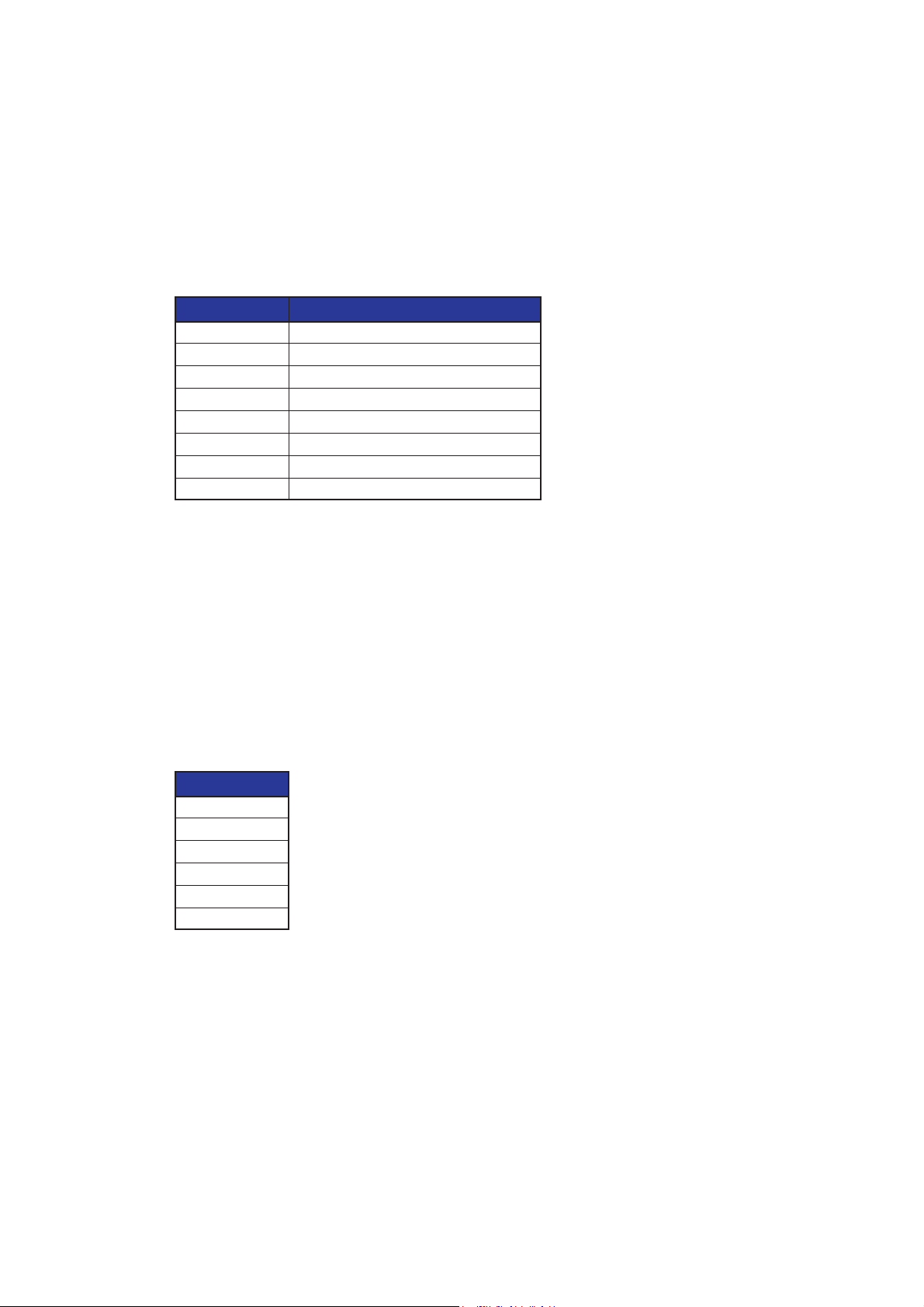
Parameter Meaning
[Sensor] #### mV Output voltage of the sensor
Akku #,## V Output voltage of the battery
Operation hours: Operation hours since last service
Total: Total operation hours
Next unit check: Date of the next recommended service
Service tel.: Phone number of the next service center
Parameter Meaning
Program version: Software version
Serial no.: Serial number of the instrument
CO purges: Amount of CO switch-offs
Error counter: Amount of errors
Parameter Meaning
Last service (history) Collection of the last maintenance
Page 50
ecom-EN3
Page 51

9. Adjustments
Additionally to those ecom-EN3 functions described previously, various adjustments can be
made in the instrument, which have an effect on the measurement procedures, the
functionality or the output and display of measured values.
Parameter Meaning Adjustment Factory setting
The following adjustments are available in the Adjustments menu:
Unit
Second unit
Ref. O2 Reference O2 0,0 … 21,0 % 0,0%
Calculation and display of gas
concentrations
Second calculation and display
of gas concentrations
ppm
mg/m³
mg/kWh (undiluted)
mg/MJ (undiluted)
ppm (undiluted)
mg/m³ (undiluted)
ppm
mg/m³
mg/kWh (undiluted)
mg/MJ (undiluted)
ppm (undiluted)
mg/m³ (undiluted)
Hint
The term "undiluted" refers to the conversion of the gas concentration to a
definable reference oxygen content according to the following formula:
E
= E
ref.
21-O2
Hint
mg/kWh and mg/MJ are always calculated on 0% O2 basis.
* 21-O2
meas
ref.
meas
ppm
ppm
ecom-EN3
Page 51
Page 52
All parameters in the table on the
Settings for the USB interface
Parameter Meaning Adjustment Factory setting
The following adjustments are available in the Adjustments menu: (continuation):
Fuel type
Set clock Correction of internal clock
Paper feed
Internal
Air leak test
Modification of adjusted
fuel type
Paper feed line by line
Further instrument
settings
-- see following table--
Check the tightness of the
instrument see Chapter 11.5
Fuel oil
Natural gas
City gas
Coke oven gas
Liquid gas
Fuel oil
The following adjustments are available in the Adjustments / Internal menu:
Parameter Meaning Adjustment Factory setting
Print contrast
Key beep
Print contrast adjustment with
cursor keys
Acoustical signal by key
pressing
9 steps Step 5
Yes, No Yes
Language: ### Selected language system dependent
Colour scheme
F1 Hotkey
F4 Hotkey
Values options
CO-Automatic
USB
Bluetooth
WLAN
Pitot factor
Printout
Sets the colours used
Assign the link using the <F1>
key
Assign the link using the <F4>
key
Adustments for efficiency,
excess air and temperature
Enable / Disable CO sensor
switches on after purging
automatically
Settings for the Bluetooth
interface
Settings for the WiFi interface All parameters in the table on
Input of Pitot factor for flow rate
calculation
Settings for defining the printout All parameters in the table on
4 schemes to choose from Colour scheme 1
see Chapter 4.1 Standby
see Chapter 4.1 Display values
following page
On, Off On
All parameters in the table on
the following page
All parameters in the table on
the following page
the following page
0,20 - 2,00 0,93
the following page
Page 52
ecom-EN3
Page 53
Not available at all instruments
Excess Air as proportionate
Efficiency
calculation with or
On, Off
Unit of draught measurement
hPa, mmH2O, “H2O, PSI, mb
ar
The following adjustments are available in the Adjustments / Internal / Values options menu:
Parameter Meaning Adjustment Factory setting
Temperature
Excess air
number or in %
Eff.(C)
without condensation gain
°C or °F °C
proportionate number or % proportionate number
On
Draught
hPa
The following adjustments are available in the Adjustments / Internal / USB menu:
Parameter Meaning Adjustment Factory setting
Transfer speed
Protocol
1200 … 115200 Baud 38400 Baud
DAS = DAS NT 2
Enhanced = DAS 5
---- = no protocol
Enhanced
The following settings are predefined in the Settings / Internal / Bluetooth (BLE) menu and can
NOT be changed:
Parameter Meaning Adjustment Factory setting
Transfer speed
Protocol
115200 Baud 115200 Baud
Enhanced Enhanced
The following adjustments are available in the Adjustments / Internal / WLAN menu:
Parameter Meaning Adjustment Factory setting
Access Point
OR
Existing Network
Set whether the instrument is to
be used as a WiFi access point
OR
to connect to an existing WiFi
network
Access Point,
Existing Network
Access Point
ecom-EN3
Hint
The Access Point setting is necessary to connect the ecom-EN3 to mobile
devices (smartphones, tablets) via the Wi-Fi interface.
Activate "Access Point" to connect the ecom-EN3 with mobile
devices via WLAN / Wi-Fi.
Page 53
Page 54

The following settings are available in the Adjustments / Internal / WiFi menu if the instrument
has been defined as an access point:
Parameter Meaning Adjustment Factory setting
Start / Stop WLAN
(Without) Auto Connect
Channel
Activate the
WiFi interface
(available only with deactivated
Auto Connect)
Enable / Disable automatic
connection
Set which radio channel is to be
used for the communication
Start WiFi, Stop WiFi -
Yes, No Yes
1 … 13 1
Security
Assign a password to secure
the WiFi connection
Yes, No
Password entry
No
1234567890
The following settings are available in the Adjustments / Internal / WiFi menu if the instrument
has been defined as an existing network:
Parameter Meaning Adjustment Factory setting
Start / Stop WLAN
(Without) Auto Connect
Existing Network
WPA-Password
Activate the
WiFi interface
(available only with deactivated
Auto Connect)
Enable / Disable automatic
connection
Search for Existing Network
Assign a password to secure
the WiFi connection
Start WiFi, Stop WiFi -
Yes, No Yes
Password entry
The following adjustments are available in the Adjustments / Internal / Printout menu:
Parameter Meaning Adjustment Factory setting
Footer for the Printout
Selection of measurement and
calculation values for printout
8 x 24 signs
Hint
The footer of the printout can be defined as desired, e.g. to print out the
company address of the instrument user on every printout of the measured
values.
To adjust the footer of the printout, proceed as follows:
1. Activate character selection list with <F4>.
2. Select keyboard type with <F3>
(4 different keyboards available).
3. Use the cursor keys to select the desired character (selected
character is outlined by black background).
4. Confirm selection while pressing <Enter>.
5. Repeat procedure until desired text is complete.
6. Once input for line 1 is completed, deactivate the characters
selection mode with <F4> and move to the second line with the
cursor key <Down>.
7. Once all lines have been processed as desired, exit the menu with
<ESC>.
Page 54
ecom-EN3
Page 55

Hint
The number and order of the measured values on the printout can be defined as
desired.
To adjust the number and order of the measured values on the
printout, proceed as follows:
1. Use the <F1> key to activate the value selection
2. Navigate to the corresponding line <up / down>
3. Select the measured value by pressing the <Enter> key
The following measurement and calculation values can be selected for the lines of the
printout:
1 T.Air 26 CO mg/N 51 SO2 mg/kWh
2 T.Gas 27 CO mg/kWh 52 SO2 mg/MJ
3 T.Boiler 28 CO mg/MJ 53 H2
4 T.Sensor 29 NO ppm 54 H2S
5 O2 30 NO ppm/N 55 Gas speed
6 CO 31 NO mg 56 Mass flow
7 NO 32 NO mg /N 57 CO x% Italy
8 NO2 33 NO mg/kWh 58 Eff._Hs
9 NOx 34 NO mg/MJ 59 Difference Temperature
10 SO2 35 NO2 ppm 60 Not used
11 CxHy 36 NO2 ppm/N 61 H2 ppm
12 CO2 37 NO2 mg 62 H2 ppm/N
13 Efficiency 38 NO2 mg/N 63 H2 mg
14 Losses 39 NO2 mg/kWh 64 H2 mg/N
15 Excess Air 40 NO2 mg/MJ 65 H2S ppm
16 Dew point 41 NOx ppm 66 H2S ppm/N
17 Poison Index 42 NOx ppm/N 67 H2S mg
18 Draught 43 NOx mg 68 H2S mg/N
19 Soot 44 NOx mg/N 69 Air pressure
20 Oil trace 45 NOx mg/kWh 70 Not used
21 Blank Line 46 NOx mg/MJ 71 CO Unit 2
22 Line 47 SO2 ppm 72 NO Unit2
23 CO ppm 48 SO2 ppm/N 73 NO2 Unit 2
24 CO ppm/N 49 SO2 mg 74 NOx Unit 2
25 CO mg 50 SO2 mg/N 75 SO2 Unit 2
ecom-EN3
Page 55
Page 56
10. Data processing
10.1 Storage on MM card
Hint
When an MM card is inserted into the instrument, it is used to store measured
values and plant data. This storage must be triggered manually or can be
automated (data logger)
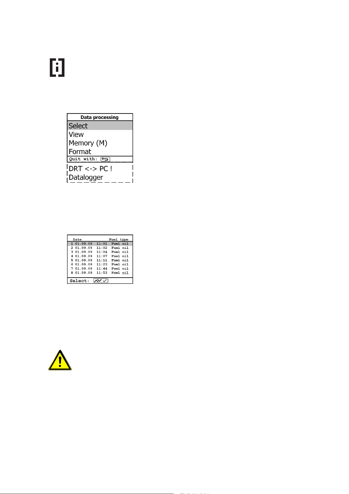
By selecting the menu item "Select", plants for the
assignment of measured values can be searched for or
set up (for further information see chapter "Measurement
procedure gas analysis: Data processing").
By selecting the menu item "View", stored measured
values can be viewed (for further information see chapter
"Measurement procedure gas analysis: Data
processing").
By selecting the menu item "Memory (M)", all stored
measurements (sorted by record number) can be viewed.
Single measurement results can be called up as
follows:
- Select desired record number with the
cursor keys and confirm with <Enter>
- confirm desired record number with
<Enter>
- Scroll with the cursor keys <up/down>
- Press <ESC> to exit
By selecting the "Format" menu item, the entire MM card can be formatted. This
function is usually needed by initial adjustment of the instrument at our factory
(preparation of MM card for data recording).
WARNING When the "Format" menu item is selected and confirmed, all stored data on
the MM card inserted in the instrument will be irrevocably deleted.
Select the menu item "Format" only if ALL data present on
the MM card are no longer required.
Page 56
ecom-EN3
Page 57

10.2 Data logger
When a MM card is inserted into the instrument, a data logger recording can be performed.
The measured values are stored one after the other on the MM card depending on the
recording interval set and are merged into a file with the format * .csv.
The measured values can be evaluated using MS Excel or open office CALC.
Hint
The data logger is ONLY available when a MM card is inserted into the
instrument.
To use the data logger, insert a MM card into the instrument.
The following adjustments are available in the Data processing / Data logger menu:
Parameter Meaning Adjustment Factory setting
Data logger
Start, Stop Data logger
Yes, No No
Save to MMC Adjustment of the interval time
for data logger recordings
CSV-Header
Adjustment of data logging with
or without column headings
1 … 999 s 1 s
On, Off Off
If the data logger becomes active or becomes active again after an interruption, a new file is
created on the MM card, in which all subsequent measured values of the recording are
saved. The files have a predefined name and are numbered consecutively.
Hint
Each measurement is assigned its own file with collected measured values. Each
file is automatically named and numbered.
To select the correct data logger file use the date identification:
J2KDL-00.csv -- oldest file
J2KDL-01.csv
J2KDL-02.csv
J2KDL-XX.csv -- newest file
ecom-EN3
Page 57
Page 58
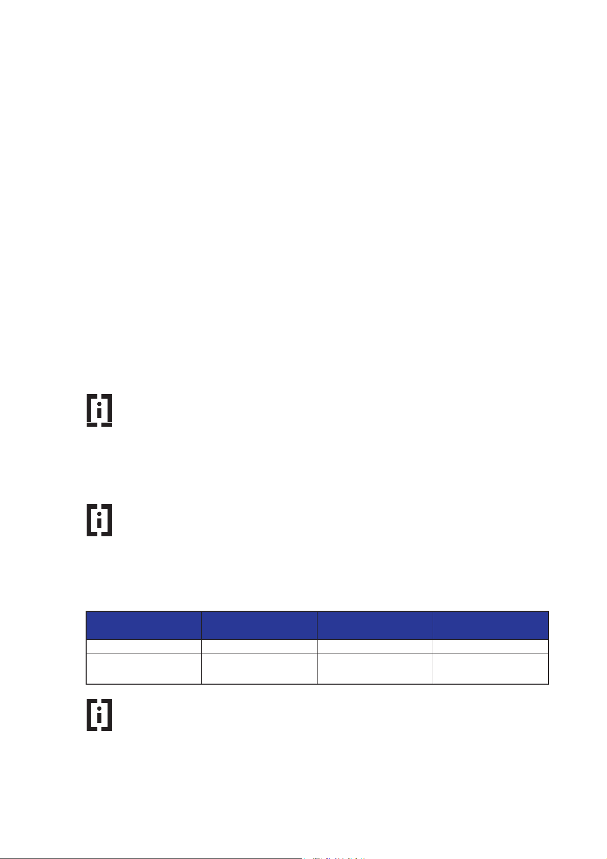
10.3 Data connection to PC
If the device is connected to a PC, measured values and plant data can be synchronized with
a PC software from ecom.
The following software solutions are available:
- ecom-DAS NT 2 (10.3.1)
- ecom-DAS 5(10.3.2)
- PC software (10.3.3)
10.3.1 Data recording with PC Software ecom-DAS NT 2
In addition to data logger recordings the data could also be transferred online via USB or AUX
to the software "ecom-DAS NT 2".
The following interfaces can be used for communication with the software:
- USB
- AUX = RS232
Hint
A driver is required to communicate with the PC software DAS NT 2 via the USB
interface.
To download and install the necessary USB driver, see
https://www.ecom.de/en/downloads/
Hint
The transmission speed and the protocol are pre-defined for the smooth
communication of the instrument with the PC software DAS NT 2 via USB
interface.
To enable communication with the PC software DAS NT 2, the
following settings must be made in the menu Adjustments / Internal /
USB:
Parameter Meaning Adjustment
Required setting
for DAS NT 2
Transfer speed
Protocol
1200 … 115200 Baud 1200 Baud
DAS = DAS NT 2
Enhanced = DAS 5
---- = no protocol
DAS
Hint
For further information on importing from the PC software and exporting to the
PC software, please refer to the operating instructions of the corresponding PC
software.
Page 58
ecom-EN3
Page 59

10.3.2 Data recording with PC Software ecom-DAS 5
The software "ecom-DAS 5" can be used to display and record measured values. Via the MM
card, customer and measurement data can be exchanged between the software and the
instrument. A recording of point and continuous measurements can be done via USB or
WLAN.
Hint
A driver is required to communicate with the PC software DAS 5 via the USB
interface.
To download and install the necessary USB driver, see
https://www.ecom.de/en/downloads/
Hint
The protocol is pre-defined for the smooth communication of the instrument
with the PC software DAS 5 via USB interface.
To enable communication with the PC software DAS 5, the
following settings must be made in the menu Adjustments / Internal /
USB:
Parameter Meaning Adjustment
Required setting
for DAS 5
Transfer speed
Protocol
1200 … 115200 Baud 1200 … 38400 Baud
DAS = DAS NT 2
Enhanced = DAS 5
---- = no protocol
Enhanced
Hint
For the smooth communication of the device with the PC software ecom-DAS 5
via the interface WLAN, setting parameters are predefined.
To enable communication with the PC software DAS 5, the
following settings must be made in the menu Adjustments / Internal /
WLAN:
Parameter Meaning Adjustment
Required setting
for DAS 5
Access Point
(Without) Auto Connect
Access Point, Existing
Network
Yes, No Yes
Access Point
Hint
For further information on importing from the PC software and exporting to the
PC software, please refer to the operating instructions of the corresponding PC
software.
ecom-EN3
Page 59
Page 60

10.3.3 Data recording with PC Software: Import and Export of Data
Hint
With the PC software "MiniDV", plant data can be quickly and conveniently
created and managed. These plant data can be imported into the instrument in
order to store measured values under these plant data.
To import plant data from the PC software into the instrument,
proceed as follows:
- Connect ecom-EN3 and PC via USB cable.
(if the connection is correct, "USB" appears in the lower right
corner of the display)
- Select “Load data“ and confirm with <Enter>.
- Answer the displayed question with YES (<F1>).
- Decide if the data recorded can be cancelled (<F1> for YES /
<F4> for NO).
- Start the data transfer on your PC.
Hint
The instrument is used to add measured values to plant data, which were
created before with the PC software. These complete data sets, consisting of
plant data and measured values, can be exported from the instrument and
managed in the PC software "MiniDV".
To export data from the instrument to the PC software, proceed as
follows:
- Connect ecom-EN3 and PC via USB cable.
(if the connection is correct, "USB" appears in the lower right
corner of the display)
- Select “Send data“ and confirm with <Enter>.
- Answer the displayed question with YES (<F1>).
- Start the data transfer on your PC.
Page 60
ecom-EN3
Page 61
Display App
10.4 Data recording with App via WiFi
To display and storage of measured values, the Apps "ecom connect WiFi" and
“ecomMANDER” for smartphones are available.
The following operating systems are supported by the Apps:
- iOS
- Android
If the instrument is connected to the App via WiFi, the current measured values of the
instrument can be displayed directly in the App.
The measured values can be saved and exported together with the customer information to
be entered. These exported data can be sent for example by e-mail.
The following file formats can be exported:
- *.pdf
- *.csv
Hint
For the smooth communication of the instrument with the Apps via WiFi, setting
parameters are predefined.
To enable communication with the Apps, the following settings
must be made in the Adjustments / Internal / WLAN menu:
Parameter Meaning Adjustment
Access Point
(Without) Auto Connect
Required setting
for Remote
Access Point,
Existing Network
Yes, No Yes
Access Point
ecom-EN3
Page 61
Page 62
App
10.5 Data recording with Apps via BLE
To display and storage of measured values, the Apps "ecom connect BLE" and
“ecomMANDER” for smartphones are available.
The following operating systems are supported by the Apps:
- iOS
- Android
If the instrument is connected to the App via Bluetooth (BLE), the current measured values of
the instrument can be displayed directly in the App.
The measured values can be saved and exported together with the customer information to
be entered. These exported data can be sent for example by e-mail.
The following file formats can be exported:
- *.pdf
- *.csv
Hint
For the smooth communication of the instrument with the Apps via Bluetooth
(BLE), setting parameters are predefined.
To enable communication with the Apps, the following settings
are fixed in the Adjustments / Internal / Bluetooth menu:
Parameter Meaning Adjustment
Required setting
for ecom connect
Transfer speed
Protocol
Enhanced
115200 Baud
Page 62
ecom-EN3
Page 63
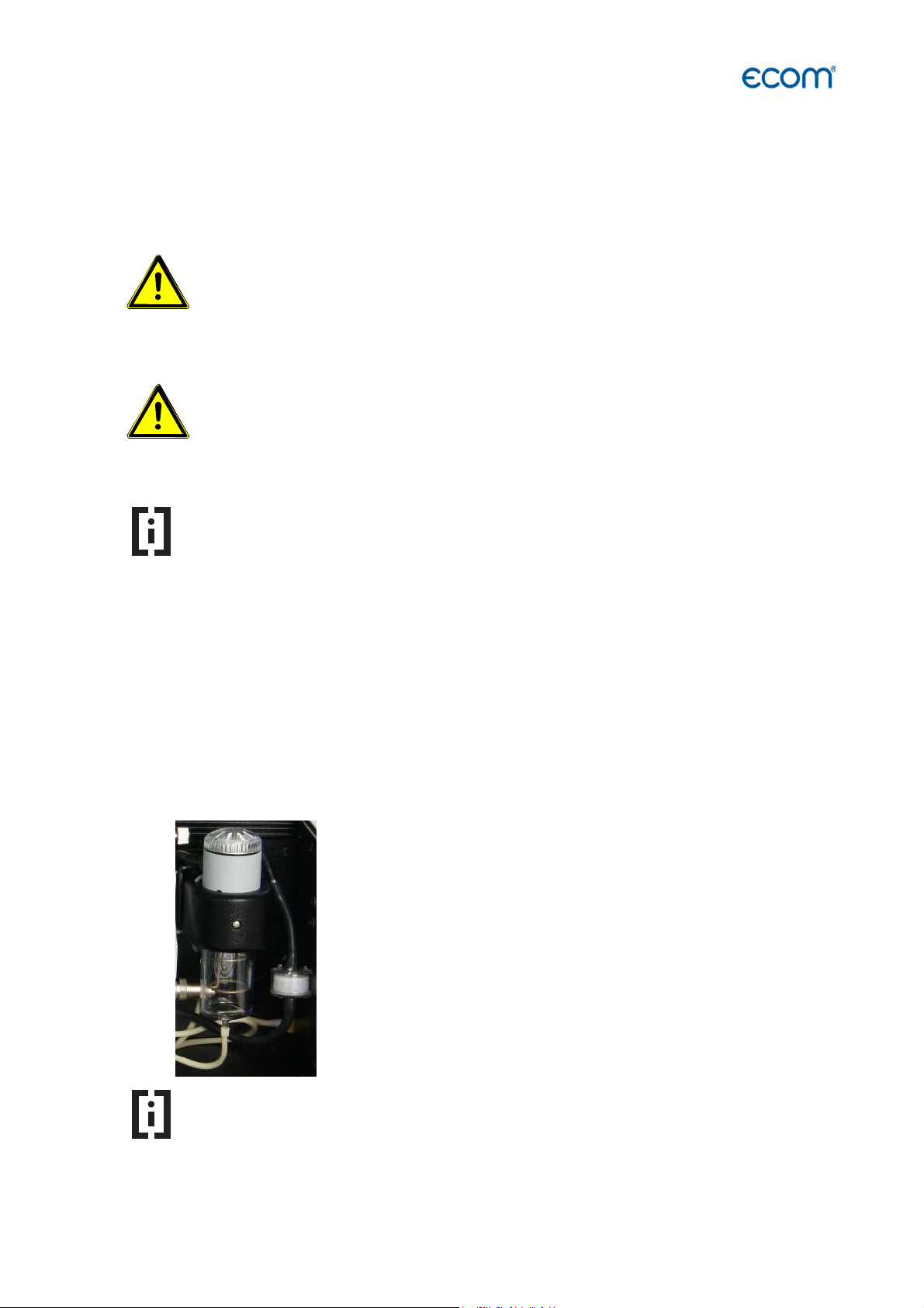
11. Maintenance Tips
To secure the accuracy of your measuring instrument we recommend the annual check by an
authorized ecom partner.
WARNING If sensors from other manufacturers are used, the TüV approval of the
instrument expires.
Use only sensors from ecom or from an ecom authorized service
centre.
WARNING Service made by service centres non-authorised by ecom GmbH will result in a
complete and immediate loss of any warranty!
authorized service centre.
Have service work performed only by ecom or by ecom
Hint
In the case of strong use (e.g. permanent several hours of measurement per
day, rough conditions etc.) shorter intervals between checks should be
selected.
Please contact your ecom partner. All ecom partners are listed
under www.ecom.de.
The following components should be checked every time the instrument is used:
11.1 Fine dust filter
Procedure for testing:
ecom-EN3
1. Unscrew the cap.
2. Check the condition of the particle filter.
3. Replace the cap.
Hint
Change the fine dust filter once the filter has a grey colour.
Replace the fine dust filter if the filter has a gray colour of 2 ... 3 on
the soot comparison scale.
Page 63
Page 64

Page 65

11.2 Gas sensors
The sensors get calibrated with the reference gas fresh air by each switch-on.
New sensors age along the operation time because of the wearing of the reagents (oxygen
sensor) and due to soiling respectively exceeding concentrations beyond the nominal
measurement range (toxic sensors).
Their state of the sensors is permanently checked by the instrument.
The output values of the sensors are listed in the menu "Control". The reference values of
the sensors are:
Sensor Reference value output voltage
O2 12000 mV
Others 0 mV (+/- 150 mV)
Hint
If an error message occurs during the calibration phase, a further calibration
phase can help to calibrate all installed sensors sufficiently.
If after several repetitions of the calibration phase an error message
occurs during the calibration phase, the instrument has to be checked.
Hint
The O2 sensor must display a value > 7000 mV.
If an output voltage <7000 mV is displayed in the "Control" menu
after the calibration phase, the O
sensor must be replaced.
2
Hint
The CO sensor is protected against overload by the internal programme.
For further information on CO overload protection, please refer to
the chapter "CO-Overload Protection"
11.3 Probe and tubing
Depending on the frequency of use, probe and tubing should be regularly cleaned in order to
release particle deposits and to prevent early wearing due to corrosion.
The hose can be cleaned (flow warm water in then dry respectively blow water drops out)
after loosening all plug-in connections on the instrument and on the probe.
O-rings of the hose connections should occasionally be greased with acid-free grease.
ecom-EN3
Page 63
Page 66

11.4 Printer paper
Replace the printer paper as follows:
Unlock the printer by pulling on the tab on the printer cover. Remove the plastic holder of the
spent paper roll and insert the new paper roll as shown. Leave some paper stand out and
close the printer cover.
1
2
3
1 2
Tab of the printer cover
Printer cover
3
Paper roll
Page 64
ecom-EN3
Page 67

11.5 Air leak test
An air leak test can be carried out in order to rule out the possibility of leaks, damage and
leaks in the system.
The instrument performs the tightness test procedure to check for leaks in probe, probe
tubing or gas path.
Hint
Carry out the air leak test at regular intervals to ensure that there are no leaks
in the instrument which could falsify the measured values.
To start the
select the air leak test.
To perform the
instrument display and observe the following:
- the gas probe must be sealed with a suitable plug
- the flow indicator (FLOW) must drop during the air leak test to 0
(red) (see flow display)
- the test procedure air leak test must be carried out
completely, all queries in the instrument display must be
processed
air leak test
air leak test
, navigate to the Adjustments menu and
, follow the on-screen instructions on the
If the air leak test is completed, remove the plug from the probe. The
instrument is now ready to measure.
ecom-EN3
Page 65
Page 68

12. Technical Data
adjustable
)
Parameter Range Principles
O2 0 ... 21 vol.% electrochemical
CO 0 ... 2500 ppm electrochemical
NO (Option) 0 ... 5000 ppm electrochemical
NO2 (Option) 0 ... 1000 ppm electrochemical
SO2 (Option) 0 ... 5000 ppm electrochemical
H2S (Option) 0 ... 1000 ppm electrochemical
CO% (Option) 4000 ... 63000 ppm electrochemical
CO2 (Option) 0 ... 20 vol.% infrared
CO2 0 ... CO2max calculated
T.Gas 0 ... 500 °C NiCr-Ni
T.Air 0 ... 99 °C Semi-conductor
Pressure 0 ... +/- 100 hPa DMS bridge
Efficiency 0 ... 120 % calculated
Losses 0 ... 99,9 % calculated
Excess air 1 ... ∞ calculated
CO-undiluted
(Reference-O2
calculated
Flue gas dew point
calculated
Power Supply: Battery charger: 230 V / 50 Hz~; Battery: 7,20 V / 11,6 Ah
Protocol printer: integral; 58 mm paper width; individual footer printout
Indication: graphic display; backlit
Dim. (W x H x D): (400 x 275 x 205) mm
Weight: approx. 7 kg complete with sampling system
Limits:
Ambient temperature: +5 … +40 °C
Humidity: max. 90 % rF, not condensing
Transport and operation of the instrument only in the following transport variants:
- Transport variant aluminium-framed transport case
- Transport variant professional case
Page 66
ecom-EN3
Page 69

Subject to technical changes
V 1.10 / 07.2019
ecom GmbH
Am Großen Teich 2
D-58640 Iserlohn
Phone: +49 (0) 2371 - 945-5
Fax: +49 (0) 2371 - 40305
Internet: http://www.ecom.de
eMail: info@ecom.de
ecom-EN3
Page 67
 Loading...