

Page 1
TX-E721 Fresnel Lens Pet Immune PIR
Description
This is the Installation Sheet for the TX-E721 Fresnel Lens Pet Immune PIR
A motion sensor (passive-infrared or PIR) detects movement within a
specific area by sensing the infrared energy emitted from a body as it
moves across the sensor’s field of view. When this motion is detected, the
sensor transmits an alarm signal to the control panel.
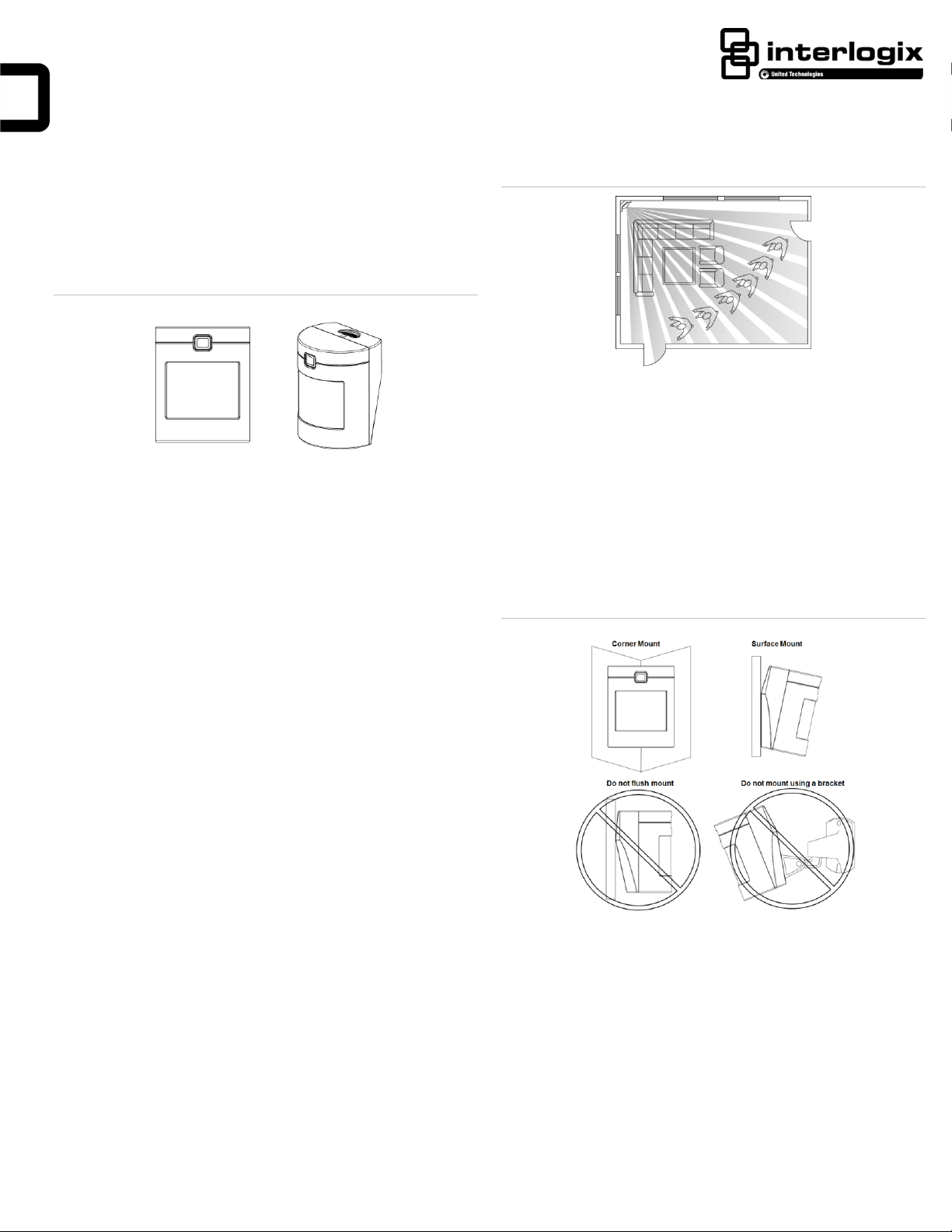
Figure 1: Pet Immune SAW PIR Motion Sensors
Use these motion sensors to protect locations where door/window sensors
are impractical or not needed. For example, use a motion sensor to protect
large areas or open floor plans. Motion sensors also provide backup
protection for door/window sensors.
The Pet Immune TX-E721 utilizes advanced signal processing, a new
custom designed lens, and a new custom designed sensing element. The
combination of these improvements provides false alarm immunity for pets
with a combined weight of up to 40 pounds while still providing superior
human catch performance.
These wireless motion sensors include the following features:
• 35 by 40 ft. (10.6 m by 12 m) coverage area.
• Three minute transmitter lockout time after an alarm that helps extend
battery life.
• Cover-activated tamper
• Supervisory signals transmitted every 64 minutes to the control panel.
• Sensor low battery reports (trouble) to the control panel.
• Field-selectable sensitivity options.
Figure 2: Overhead Detection Path
• Mount the motion sensor on a rigid surface which is free from
vibrations.
• Do not mount the sensor near duct work or other large metallic
surfaces which may affect the RF signals (see RF Testing). Actual
acceptable transmitter range should be verified for each installation.
• Mount the sensor permanently on a flat wall or in a corner. Do not set it
on a shelf.
• Windows should be closed in any area which has an armed motion
sensor.
• The sensor must be incline-mounted at a mounting height of 7.5 ft. See
Figure 3.
Figure 3: Wall Mount Options
Installation
Installation Guidelines
• Temporarily place the sensor in its intended mounting location.
Program and final test the sensor before permanently mounting it.
• If possible, locate sensors within 100 ft. (30.5 m) of the panel. While a
transmitter may have a range of 500 ft. (152 m) or more out in the
open, the environment at the installation site can have a significant
effect on transmitter range. Sometimes a change in sensor location
can help overcome adverse wireless conditions.
• The recommended mounting height is 7 1/2 ft.
• Position the sensor to protect an area where an intruder would be most
likely to walk across the detection pattern See Figure 2.
P/N 466-5305 • Rev A • 24JAN17 1 / 4
• Room temperature must be kept between 60° and 120°F (16° and 49°
C).
• Position the sensor so it faces a solid reference point, like a wall.
Programming
Refer to the panel documentation for information on programming the
sensor into the panel.
To Trip the Sensor
1. Set the panel to program mode.
2. Proceed to the Learn Sensors menu.
Page 2
3. Remove the PIR from its mounting plate (activating the tamper switch).
4. Select the appropriate sensor group and number.
5. Exit the panel’s programming mode.
6. Return the PIR to its mounting plate.
Final Testing
Final testing should be done to verify radio signal integrity and confirm
control panel programming and response. The actual transmitter range can
be determined by performing a sensor test as follows:
1. With the PIR temporarily mounted at its intended location, remove the
PIR from its mounting plate and activate the tamper switch to start the
walk test mode.
2. Replace the sensor in its mounting plate.
3. Place the control panel in Sensor test mode. Move across the
detection pattern until the sensor’s LED turns on. STOP your motion.
4. Listen for the appropriate system response. Refer to the specific panel
installation manual for details on system response. If the system does
not respond as expected, proceed to the “Error! Reference source
not found.” section.
Mounting
The sensors must be incline-mounted on a wall surface or incline-mounted
in a corner at a mounting height of 7.5 ft. (2.5 m).
To Mount the Sensor
1. Remove the mounting plate by depressing the button on the top of the
sensor body. With the opposite hand pull the mounting plate away from
the body of the sensor.
2 Punch out the mounting holes that best fit your application. See Figure
3 for wall mount options.
3. See Figure 4 to determine which knockouts to use when mounting the
motion sensor. Use the outside 4 holes for corner mounting, or the
inside 4 holes for surface mounting.
Note: If the shorting jumper is not used or is placed incorrectly, the sensor
defaults to standard sensitivity.
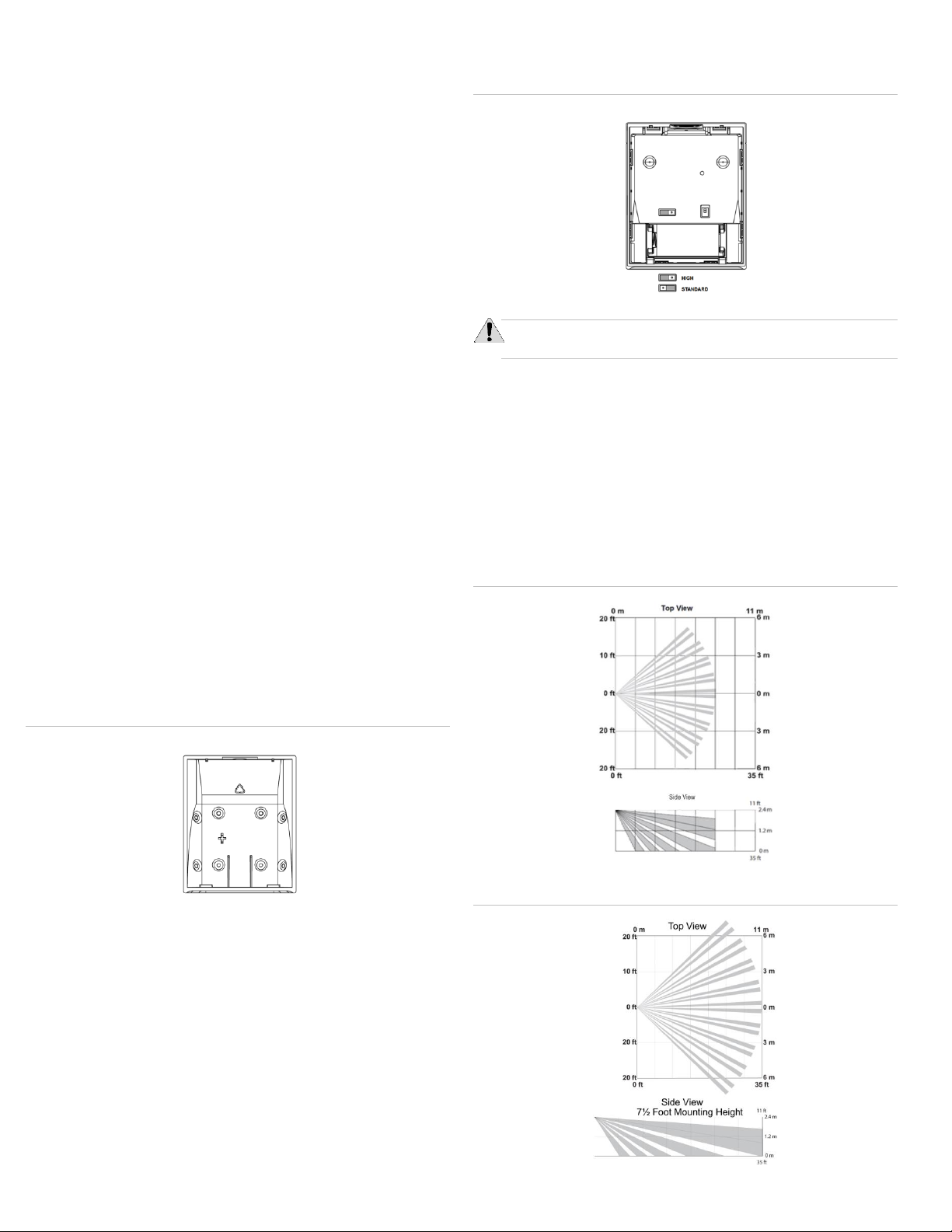
Figure 5: Sensitivity Pin Locations
CAUTION: High sensitivity should only be used in environments where
the room temperature is very stable.
1. Remove the mounting plate by depressing the button on the top of the
sensor body. With the opposite hand pull the mounting plate away from
the body of the sensor.
2. Locate the sensitivity pins directly above the battery when looking at
the back of the PIR
3. To change to high sensitivity, move the shorting jumper to the pair of
pins that are closer to the left side of the PIR
4. Walk test the PIR to verify the sensitivity.
The difference between the two settings are indicated in Figures 6 and
7.below.
Figure 6: Standard Sensitivity Setting
Figure 4: PIR Mounting Plate Knockouts
4. Mark the location of the required holes on the mounting surface.
5. Use wall anchors and screws to secure into place. Attach the sensor to
the mounting plate.
6. When testing is completed the PIR can be securely attached to its
mounting plate by screwing the smallest enclosed screw into the hole
at the top of the mounting plate.
Figure 7: High Sensitivity Setting
Setting the Sensitivity
The PIR has two sensitivity settings (standard and high sensitivity). The
sensor is set to standard sensitivity at the factory. This sensitivity is
preferred for most applications and provides the best immunity to false
alarms.
2 / 4 TX-E721 PET Immune PIR Motion Detector Installation Sheet
Page 3

Important information Regarding Sensitivity Settings
RF Frequency
319.5 MHz
Compatibility
Interlogix 319.5 MHz control panels/receivers
Battery Type
CR123A
Typical Battery Life
Up to 5 years at 68° F (20° C)
Operating
Temperature Range
32° to 110°F (0° to 43°C) Non-pet
applications
60° to 110°F (16° to 43°C) Pet applications
Supervisory Interval
64 Minutes
Relative Humidity
0 – 90% non-condensing
Storage Temperature
Range
-30 to 140°F (-34 to 60°C)
Dimensions
(L x W x H)
2.5 in x 2.1 in x 3.0 in
The sensitivity settings should be set as followed:
Standard Sense:
Rooms < 25ft
Pets < 40 pounds
High Sense:
Rooms < 35ft
Pets < 20 pounds
Testing
Walk Testing
Walk testing should be done to determine the sensor’s actual coverage
area. The edge of the coverage pattern is determined by the first flash of the
LED. This may change slightly depending upon the sensitivity setting. Walk
test the unit from both directions to determine the pattern boundaries.
CAUTION: Excessive use of the walk test mode may reduce battery
life. Use only for initial setup and maintenance testing.
1. Remove the sensor body from the mounted mounting plate and then
remount the body to activate the 60 second walk test mode.
2. Walk across the coverage pattern to determine the coverage area,
indicated by LED activation. Each activation extends the walk test
mode for an additional 60 seconds.
After 60 seconds without motion the walk test mode and the LED will no
longer activate when motion is detected.
Note: When the walk test mode has ended, an alarm can be transmitted
only after 3 minutes have passed since the previous alarm. This 3 minute
lockout time reduces unnecessary RF transmissions in high traffic areas
thereby extending battery life.
Environment Testing
Turn on all heating or air conditioning sources which would normally be
active during the protection period. Stand away from the sensor and outside
the coverage pattern and watch for alarms. When testing the Pet Immune
PIR also verify the pets allowed in the coverage pattern do not trip the PIR.
Maintenance
Figure 8: PIR Components, Battery Locations & Tamper Switch
Troubleshooting
Use the following guidelines if the system does not respond correctly when
the sensor final testing is conducted.
• Check programming and re-program sensor into panel if necessary.
• Move the sensor to another location and test for correct response.
• Check the mounting height and angle are according to “Mounting”
section.
To Relocate a Sensor
1. Test the sensor a few inches from the original position.
2. Increase the distance from the original position and retest until an
acceptable location is found.
3. Mount the sensor in the new location.
4. If no location is acceptable, test the sensor as described below:
• Test a known good sensor at the same location.
• If the system does not respond, avoid mounting a sensor at that
location.
• If the replacement sensor functions, return the problem sensor for
repair or replacement.
At least once a year, the range and coverage should be verified for proper
operation. The end user should be instructed to put the sensor in walk test
mode and walk through the far end of the coverage pattern to verify proper
detection.
Replacing the Battery
When the system indicates the sensor has a low battery, replace the battery
immediately.
1. Remove the mounting plate by depressing the button on the top of the
sensor body. With the opposite hand pull the mounting plate away from
the body of the sensor. See Figure 8.
2. Remove the old battery and replace with new battery (CR123A)
Note: Observe polarity when replacing the battery. The battery should
be inserted with the negative end closest to the left side of the PIR
when viewing it from the back. The positive end of the battery should
be closest to the right side. See Figure 8.
If a battery is installed incorrectly the unit will not function and
the red LED will not light up. The sensor may be damaged if a
battery is installed incorrectly.
3. Dispose of the battery as required by local requirements
4. Walk test the PIR to verify proper operation.
Note: When the battery is replaced, wait at least three minutes after
installing the battery before activating the walk test mode.
TX-E721 PET Immune PIR Motion Detector Installation Sheet 3 / 4
Specifications
TX-E721
Page 4

FCC Compliance Statement
This equipment has been tested and found to comply with the limits for a Class B digital device, pursuant to Part 15 of the
FCC Rules. These limits are designed to provide reasonable protection against harmful interference in a residential
installation.
This equipment generates, uses, and can radiate radio frequency energy and, if not installed and used in accordance with
the instructions, may cause harmful interference to radio communications. However, there is no guarantee that
interference will not occur in a particular installation.
If this equipment does cause harmful interference to radio or television reception, which can be determined by turning the
equipment off and on, the user is encouraged to try to correct the interference by one or more of the following measures:
• Reorient or relocate the receiving antenna.
• Increase the separation between the equipment and receiver.
• Connect the equipment into an outlet on a circuit different from that to which the receiver is connected.
• Consult the dealer or an experienced radio/TV technician for help.
Changes or modifications not expressly approved by UTC Fire and Security could void the user’s authority to operate
the equipment.
This device complies with Industry Canada licence-exempt RSS standard(s). Operation is subject to the following two
conditions: (1) this device may not cause interference, and (2) this device must accept any interference, including
interference that may cause undesired operation of the device.
Cet appareil est conforme avec Industrie Canada exempts de licence standard RSS (s). Son fonctionnement est soumis
aux deux conditions suivantes: (1) cet appareil ne doit pas provoquer d'interférences et (2) cet appareil doit accepter
toute interférence, y compris celles pouvant causer un mauvais fonctionnement de l'appareil.
In accordance with FCC requirements of human exposure to radiofrequency fields, the radiating element shall be
installed such that a minimum separation distance of 20 cm is maintained from the general population.
Conformément aux exigences d'Industrie Canada en matière d'exposition humaine aux champs de radiofréquences,
l'élément rayonnant doit être installé de telle sorte qu'une distance minimale de 20 cm soit maintenue par rapport à la
population générale.
FCC: XQC-TXE721
IC: 9863B-TXE721
This Class B digital apparatus complies with Canadian ICES-3B.
Cet appareil numérique de la classe B est conforme à la norme NMB-003 du Canada.
Contact information
For contact information, visit us online at www.interlogix.com.
For technical support, see www.interlogix.com/support
Copyright
Copyright © 2017 United Technologies Corporation. All rights reserved.
Trademarks
Interlogix is a registered trademark of United Technologies Corporation. Interlogix is part of UTC Climate, Controls & Security,
a unit of United Technologies Corporation.
LIMITATION OF LIABILITY
A PROPERLY INSTALLED AND MAINTAINED ALARM/SECURITY SYSTEM MAY ONLY REDUCE THE RISK OF
EVENTS SUCH AS BREAK-INS, BURGLARY, ROBBERY OR FIRE; IT IS NOT INSURANCE OR A GUARANTEE
THAT SUCH EVENTS WILL NOT OCCUR, THAT ADEQUATE WARNING OR PROTECTION WILL BE PROVIDED,
OR THAT THERE WILL BE NO DEATH, PERSONAL INJURY, AND/OR PROPERTY DAMAGE AS A RESULT.
WHILE INTERLOGIX UNDERTAKES TO REDUCE THE PROBABILITY THAT A THIRD PARTY MAY HACK,
COMPROMISE OR CIRCUMVENT ITS SECURITY PRODUCTS OR RELATED SOFTWARE, ANY SECURITY
PRODUCT OR SOFTWARE MANUFACTURED, SOLD OR LICENSED BY INTERLOGIX, MAY STILL BE HACKED,
COMPROMISED AND/OR CIRCUMVENTED.
INTERLOGIX DOES NOT ENCRYPT COMMUNICATIONS BETWEEN ITS ALARM OR SECURITY PANELS AND
THEIR OUTPUTS/INPUTS INCLUDING, BUT NOT LIMITED TO, SENSORS OR DETECTORS UNLESS REQUIRED
BY APPLICABLE LAW. AS A RESULT THESE COMMUNICATIONS MAY BE INTERCEPTED AND COULD BE USED
TO CIRCUMVENT YOUR ALARM/SECURITY SYSTEM.
WARRANTY DISCLAIMERS
INTERLOGIX HEREBY DISCLAIMS ALL WARRANTIES AND REPRESENTATIONS, WHETHER EXPRESS, IMPLIED,
STATUTORY OR OTHERWISE INCLUDING (BUT NOT LIMITED TO) ANY WARRANTIES OF MERCHANTABILITY
OR FITNESS FOR A PARTICULAR PURPOSE WITH RESPECT TO ITS SECURITY PRODUCTS AND RELATED
SOFTWARE. INTERLOGIX FURTHER DISCLAIMS ANY OTHER IMPLIED WARRANTY UNDER THE UNIFORM
COMPUTER INFORMATION TRANSACTIONS ACT OR SIMILAR LAW AS ENACTED BY ANY STATE.
(USA ONLY) SOME STATES DO NOT ALLOW THE EXCLUSION OF IMPLIED WARRANTIES, SO THE ABOVE
EXCLUSION MAY NOT APPLY TO YOU. THIS WARRANTY GIVES YOU SPECIFIC LEGAL RIGHTS AND YOU MAY
ALSO HAVE OTHER LEGAL RIGHTS THAT VARY FROM STATE TO STATE.
INTERLOGIX MAKES NO REPRESENTATION, WARRANTY, COVENANT OR PROMISE THAT ITS SECURITY
PRODUCTS AND/OR RELATED SOFTWARE (I) WILL NOT BE HACKED, COMPROMISED AND/OR
CIRCUMVENTED; (II) WILL PREVENT, OR PROVIDE ADEQUATE WARNING OR PROTECTION FROM, BREAKINS, BURGLARY, ROBBERY, FIRE; OR (III) WILL WORK PROPERLY IN ALL ENVIRONMENTS AND
APPLICATIONS.
DISCLAIMER
THE INFORMATION IN THIS DOCUMENT IS SUBJECT TO CHANGE WITHOUT NOTICE. UTC ASSUMES NO
RESPONSIBILITY FOR INACCURACIES OR OMISSIONS AND SPECIFICALLY DISCLAIMS ANY LIABILITIES,
LOSSES, OR RISKS, PERSONAL OR OTHERWISE, INCURRED AS A CONSEQUENCE, DIRECTLY OR
INDIRECTLY, OF THE USE OR APPLICATION OF ANY OF THE CONTENTS OF THIS DOCUMENT. FOR THE
LATEST DOCUMENTATION, CONTACT YOUR LOCAL
SUPPLIER OR VISIT US ONLINE AT WWW.INTERLOGIX.COM
THIS PUBLICATION MAY CONTAIN EXAMPLES OF SCREEN CAPTURES AND REPORTS USED IN DAILY
OPERATIONS. EXAMPLES MAY INCLUDE FICTITIOUS NAMES OF INDIVIDUALS AND COMPANIES. ANY
SIMILARITY TO NAMES AND ADDRESSES OF ACTUAL BUSINESSES OR PERSONS IS ENTIRELY
COINCIDENTAL.
INTENDED USE
USE THIS PRODUCT ONLY FOR THE PURPOSE IT WAS DESIGNED FOR; REFER TO THE DATA SHEET AND
USER DOCUMENTATION. FOR THE LATEST PRODUCT INFORMATION, CONTACT YOUR LOCAL SUPPLIER OR
VISIT US ONLINE AT WWW.INTERLOGIX.COM. THE SYSTEM SHOULD BE CHECKED BY A QUALIFIED
TECHNICIAN AT LEAST EVERY 3 YEARS AND THE BACKUP BATTERY REPLACED AS REQUIRED.
4 / 4 TX-E721 PET Immune PIR Motion Detector Installation Sheet
 Loading...