

Page 1

PN PIRZB1-ECO R1.00 Rev date 6/26/2017
Problem
Solution
Attempt to pair the sensor is unsuccessful.
Reset
the detector to default mode and then set to
pairing mode (see section
3.5).
The sensor and the Touchscreen (control panel)
do not
communicate.
Perform the signal strength testing procedure
described in the control panel installation manual.
Make sure that the signal is sufficient. If
necessary,
replace the sensor’s battery.
The sensor sends a Low Battery
indication.
To
ensure continuous proper operation, replace the
battery within two weeks of the first Low Batter
y
indication.
Panel does not arm because of an unrecognized
sensor
malfunction.
Consult with your installer or system provider bef
ore
you disable a zone. Disable the sensor zone (see
the control panel user manual). Note that disa
bling
a sensor zone lowers the overall security level of
your system.
4.
TROUBLESHOO
TING
If you encounter one of the following problems with the PIRZB1-ECO,
resolve
the problem:
5. SPECIAL
Even the most sophisticated detectors can sometimes be defeated or may fail to warn due to: DC
/
improper connection, malicious masking of the lens, tampering with the optical system, decreased sensitivity in
ambient temperatures close to that of the human body and unexpected failure of a component part. The above list
includes the most common reasons for failure to detect intrusion, but is by no means comprehensive. It is therefore
recommended that the detector and the entire alarm system be checked weekly, to ensure
alarm system should not be regarded as a substitute for insurance. Home and property
prudent enough to continue insuring their lives and property, even though they are
COMMENTS
6. COMPLIANCE WITH STAND
FCC Statement: This equipment has been tested and found to comply with the limits for a Class B
FCC Rules. These limits are designed to provide reasonable
generates, uses and can radiate radio frequency energy and, if not installed and used in accordance with the instructions, may cause harmful
interference to radio communications. However, there is no guarantee that interference will not occur in a
equipment does cause harmful interference to radio or television reception, which can be determined by turning the equipment off and on,
the user is encouraged to try to correct the interference by one of the following measures:
•
Reorient
or
relocate
the
•
Increase
the
separation between
•
Connect the equipment into an outlet on a circuit dif
•
Consult
the
dealer
or an
This device complies with Part 15 of the FCC Rules. Operation is subject to the following two conditions:
(1) This device may not cause harmful interferene and (2) this device must accept any interference received, including interference that may
cause undesired operation.
Warning:
Changes or modifications not expressly approved by the Ecolink Intelligent Technology Inc.
the equipment.
This device complies with Industry Canada license-exempt RSS standard(s). Operation is subject to the
following two conditions: (1) this device may not cause interference, and (2) this device must accept
interference, including interference that may cause undesired operation of the device.
Cet appareil est conforme avec Industrie Canada exempts de licence standard RSS (s). Son fonctionnement est
soumis aux deux conditions suivantes: (1) cet appareil ne doit pas provoquer d'interférences et (2) cet appareil
doit accepter toute interférence, y compris celles pouvant causer un mauvais fonctionnement de l'appareil.
In accordance with FCC requirements of human exposure to radiofrequency fields, the radiating element shall be
installed such that a minimum separation distance of 20 cm is maintained from the general population.
Conformément aux exigences d'Industrie Canada en matière d'exposition humaine aux champs de
radiofréquences, l'élément rayonnant doit être installé de telle sorte qu'une distance minimale de 20 cm soit
maintenue par rapport à la population générale.
FCC ID: XQC-PIRZB1ECO
IC ID: 9863B-PIRZB1ECO
Installation shall be done in accordance with the Standard for Installation
protection against harmful interference in a residential installation. This equipment
receiving
antenna.
the
equipment
experienced radio/TV technician
and receiver.
ferent from that to which the receiver is
use the following solutions to
power failure
proper performance. An
owners or renters should be
protected by an alarm system.
ARDS
digital
device, pursuant to Part 15 of the
particular installation. If this
connected.
for help.
could void the user’s authority to operate
any
and Classification of Burglar and Holdup Alarm Systems, UL
681.
PIRZB1-ECO
Wireless Digital Pet Resistant PIR
rd
3
Party Certifications: FCC, IC, ETL, ZigBee HA, iControl
Detector
Installation Instructions
1. INTRODUCTION
The PIRZB1-ECO
microprocessor-controlled wireless digital PIR
detector supported by ZigBee Home
1.2.
The detector’s fe atures are as follows:
A. Red LED
B. Green LED
C. Tamper
2.
SPECIFICA
Detector Type: Two - Dual element low-noise pyroelectric sensor
Optical Data:
Max. Coverage: 15 x 15 m, (49.2 x 49.2 ft)
Pet
Immunity:
ELECTRICAL
Internal
Nominal Battery
Battery Life (with LED on): Typically over 5 years
Battery Power Test: Performed immediately upon battery insertion and during each transmission to the panel
FUNCTIONAL
Alarm
Visual
Rearm Timer: Rearms the detector 2 minutes after the last alarm. Timer disabled in the walk test mode.
WIRELESS
Supported
Frequency: 2.405 – 2.480
Tamper
MOUNTING
Height:
Installation
ENVIRONMENTAL
Operating Temperatures -10˚ C to 55˚ C (14˚ F to 131˚ F)
Storage Temperatures -20˚ C to 65˚ C (-4˚ F to 149˚ F)
COMPLIANCE WITH STAND
USA
PHY
SICAL
Size (H x W x D) 83 x 61 x 42 mm (3.27 x 2.4 x
Weight (with battery) 90 g (3.17 oz)
Color White
pet resistant detector is a
Automation
Switch
TIONS
Batteries:
Capacity:
Period:
Indications:
Network:
Alert:
Options:
ARDS
18
parabolic mirrors for long range
18
parabolic mirrors for close range
Selectable: (1.No immunity 2. Up to 40 lb 3. Up to 85 lb)
Two 3V Lithium batteries, type CR-123A. For UL installations, use Panasonic
1400 mAh per battery
Note: Inability to connect with wireless network, or wireless link quality resulting in intermittent connection ma
significantly reduce the expected battery
3 seconds
Red LED lights for about 3 seconds upon transmission of alarm & tamper messages and upon
Detection in the walk test mode only (walk test mode available for approx. 15 minutes). Red LED
the power-up st abilization period, or after restoring (pressing) the tamper switch (power-up stabilization
approx. 1 minutes). LED does not light upon transmissions of supervision messages or alarm detection
termination of walk test mode.
ZigBee H.A
Reported when a tamper event occurs and in
1.8-2.4 m (6 - 8 ft). For pet rejection, the optimal height is 2.1 m (7 ft)
Surface or corner
CFR 47 part
ANSI/UL
1.2
Ghz as per IEEE
15,
639
/ 90°
802.15.4
1.66”)
only
life.
any subsequent message, until the tamper switch is restored
motion
flashes during
after
y
period is
Page 2
PN PIRZB1-ECO R1.00 Rev date 6/26/2017
3.
INST
3.1 General Guidance
1. Do not install near heating and cooling sources.
2. Do not aim detector at windows due to risk of drafts.
3. Do not install outdoors.
4. Do not install where direct sunlight can strike the
5. Do not install near high-voltage electrical lines.
6. Do not install behind any obstructions.
7. Do not mount on unstable surfaces.
ALLA
TION
unit.
Figure 2. General
Guidelines
3.4 Activating and Pairing the
To
pair the detector to the Touchscreen (control panel), you must set the detector to pairing mode.
1. First set the Touchscreen (panel) to pairing mode and then the
2. To activate, pull the activation strip that protrudes from the back of the
3. The green LED (see Figure 1) blinks 3 times every 5 seconds (repeated up to 20 times) to
that the detector is searching for the Touchscreen (control panel).
Note: If detector pairing is not successful during the searching process – by pressing the tamper
switch – the searching process will restart.
4. Complete the pairing procedure on the Touchscreen (control panel). See
the Touchscreen (control panel)
Note: Pairing should be performed before
After the installation a good link to the panel is displayed when the Received Signal
Indicator
stronger than
If the RSSI and LQI values are lower, you
(RSSI)
indicated on the panel is higher than -70dBm and the Link Quality Indicator
250.
installation guide for details..
Detector
detector
installation.
must change the location of the
.
detector
.
the pairing instructions in
Strength
detector
.
indicate
(LQI)
is
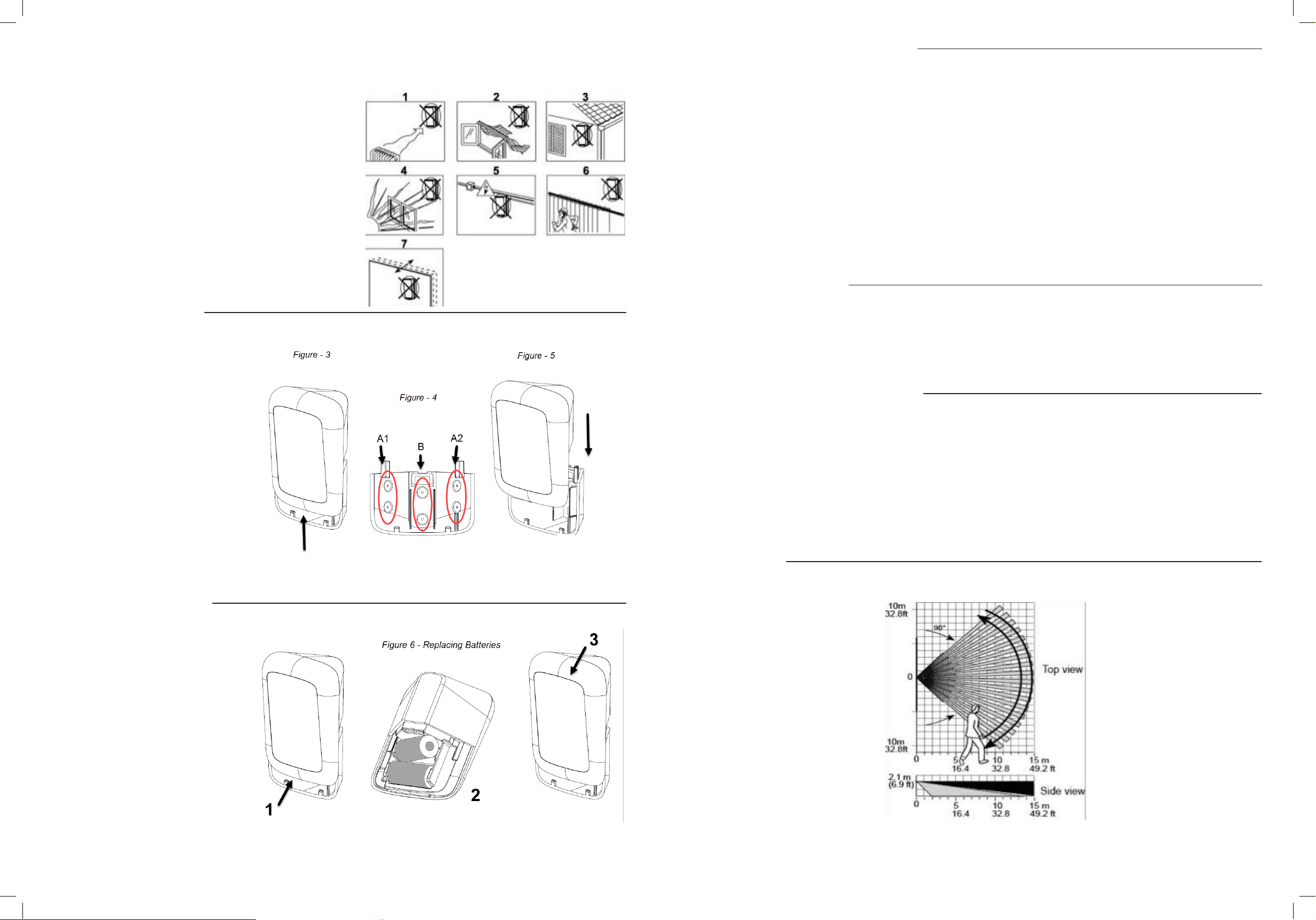
3.2 Installation Procedure
1.
Separate detector from bracket. Figure 3.
2.
Remove the bracket.
3.
Mount bracket to wall using the center
screw holes (B) or corner screw holes (A1 &
A2). Figure 4.
4.
Install new batteries OR if batteries are
installed, remove the activation strip.
5.
Remount the detector by sliding it down
onto the bracket until a click is heard. Figure
5.
6.
The unit is ready for walk test.
3.3 Replacing the Batteries
3.5 Rebooting the
To
reboot the detector, complete the following steps:
1. Remove the battery cover
2. Press and release the tamper switch (see Figure – 1) for 1 to 2 seconds
3. Close the battery cover
3.6 Return
CAUTION! The defaulting process removes the device from the network and enables
Prerequisite: Separate the detector from the bracket to remove both ba
See Figure 6 for details
1. Press
2. Insert one of the two batteries into the detector while observing battery polarity
3. Release the tamper switch within 4 seconds (the LED blinks 3 times every
4. To re-pair the detector, follow the instructions in section
Note: It is recommended to wait about 1 minute after battery removal, before inserting the new
ba
ttery.
3.7 W
Walk across the far end of coverage pattern in both directions. The LED should light for 2-3
each time your motion is detected.
the Detector to default mode
and hold down the detectors tamper switch.
alk T
esting
Detector
.
.
.
.
re-pairing.
tteries.
.
5 seconds).
3.4.
seconds
1. Press upward to separate the detector
the bracket.
2. Replace the ba
3. Put back the detector on the bracket.
Note: It is recommended to wait
approximately 1 minute after battery
removal before inserting the new
battery.
CAUTION! Risk of explosion if
battery is replace by an incorrect
type. Dispose of used battery
according to the manufacturers
instructions.
tteries.
from
Important! Instruct the user to walk test at
least once a week to verify proper function of
the detector.
Note:
After battery insertion or closing the
cover (which results in closing the tamper
switch)the LED
the detector goes into walk-test mode for
15 minutes. In walk test mode
for every motion detected. After 15 minutes
the detector automatically enters normal
in which the LED
detection.
flashes for 2 minutes and
the LED
lights
will not blink after
mode
Figure 7 – Coverage Pattern Walk-Test
 Loading...