

Page 1
Copyright © Ecolink I ntelligent Te chnology
1
Z-Wave
®
Thermostat
TBZ500
Battery Powered
Z-Wave Thermostat
Installation &
Operation Guide
TBZ500_manual_8_5x5_5_inch Combined_RDN1240221.indd 1 24-02-2021 18:55
Page 2

Copyright © Ecolink Intellig ent Tech nology
TBZ500_manual_8_5x5_5_inch Combined_RDN1240221.indd 2 24-02-2021 18:55
2
Page 3
24-02-2021 18:55
3
Table of Contents:
Thermostat Features ..................................................... 4
Standard HVAC System Connections .............................. 4
Thermostat compatible HVAC Systems ........................... 5
Battery Powered Operation ............................... 5
24VAC Powered Operation .............................. 5
Installation Steps .......................................................... 6
Remove Existing Thermostat ........................................ 6
Color Wiring Table ......................................... 6
Wiring Colors ................................................................ 7
Install Back Panel .............................................................. 7
Single Transformer System ........................................... 7
Separate Transformer HVAC System ........................... 8
Thermostat Setup .......................................................... 8
Standard System Settings ................................ 8
Two stage Heat/Cool Systems .......................... 8
Single and Dual Transformer
Systems (Split Systems) ............................................... 9
Single Transformer System .............................. 9
Dual Transformer Systems ............................... 9
Heat Pump HVAC System Wiring ............................... 10
Thermostat Setup: Heat Pump HVAC Systems .......... 11
Single Stage Heat/Cool Systems ...................... 11
Two Stage Heat/Cool Systems ........................ 11
Mount the Thermostat ................................................ 12
Battery Powered Thermostat ........................... 12
Thermostat Setup: Configure for HVAC System ........ 13
Preset HVAC System Settings ......................... 13
Changing the HVAC System Setup .................... 13
Entering Menu Mode .................................... 13
Thermostat Menu Screen .............................. 14
Menu Mode Navigation ............................. 14
System Setup Menu ..................................... 14
Advanced Systems Settings Menu ................................. 15
Settings Menu Table ...............................
15 – 17
Copyright © Ecolink Intellig ent Technology
Z-Wave Installation.....................................................
18
Adding the thermostat to a Z-Wave network ......
18
Removing the thermostat from
a Z-Wave network .....................................
18
Operation Instructions ...............................................
19
Backlight and Button Operation ......................
19
System Operation Modes ...............................
19
Stage Indicators ..........................................
19
Setting the System Mode ...........................................
20
System Modes ...........................................
20
Setting the Heating or
Cooling Temperature Setpoint .................................
21
Setpoint Change ........................................
21
Setpoint Push............................................
21
Setting the Fan Mode .................................................
22
Thermostat Menu Mode .............................................
22
Thermostat Setup Menu ...............................
23
Thermostat System Menu .............................
23
Z-Wave Menu ............................................
23
INFO Menu ...........................................23
Thermostat Operation ................................................
24
Minimum Run Tim (MRT) ..............................
24
Minimum Off Time (MOT) .............................
24
Z-Wave Operation ..........................................................
24
Thermostat Battery Operation ........................
24
Thermostat 24VAC Operation ........................
24
Adding the thermostat to a Z-Wave network ......
25
Removing the thermostat from
a Z-Wave network .....................................
25
Z-Wave Command Classes ................................................
26
Compliance Statement ..................................................
27
Limited Warranty ........................................................
27
Return Policy ...............................................................
27
TBZ500_manual_8_5x5_5_inch Combined_RDN1240221.indd 3
Page 4
TBZ500 BATTERY POWERED Z-WAVE THERMOSTAT
INSTALLATION INSTRUCTIONS
The Z-Wave Thermostat (TBZ500) is a programmable, Z -Wave communicating thermostat. It can be powered using 24VAC (if
both “R”&”C” wires are available at the thermostat) or using four (4) AA batteries. Using Z-Wave technology, end users have the
ability to use many Z-Wave enabled control panels and Z-Wave hubs to control the thermostat, configure programming settings,
as well as to display current conditions in the home or office.
Features Include:
• A fixed format display with white backlight
• Heating and cooling setup display options
• System mode (OFF, Heat, Cool,Auto, E-Heat)
• Fan mode control and display (Auto, ON)
• Changeover type for Heat Pump (HP) systems
• On-screen setup of HVAC type, Fan type
• F/C mode, and sensor calibration
Compatible with 24 VAC gas, oil, or electric heating and air conditioning systems;
or gas millivolt heating systems DO NOT USE ON 120VAC SYSTEMS!
Standard Systems
• 1 Stage Heating and Cooling
• 2 Stage Heating and Cooling
Heat Pump Systems
• 1 Stage Heating and Cooling
• 2 Stage Heating and Cooling
• 2nd or 3rd Stage Aux Heating (Electric Heat Strips)
Installation Outline
• Step 1 Remove Existing Thermostat
• Step 2 Install TBZ500 Thermostat
• Step 3 Setup Thermostat to match System Type
• Step 4 Install into Z-Wave Network
Copyright © E colink Intelligent Technology
TBZ500_manual_8_5x5_5_inch Combined_RDN1240221.indd 4 24-02-2021 18:55
4
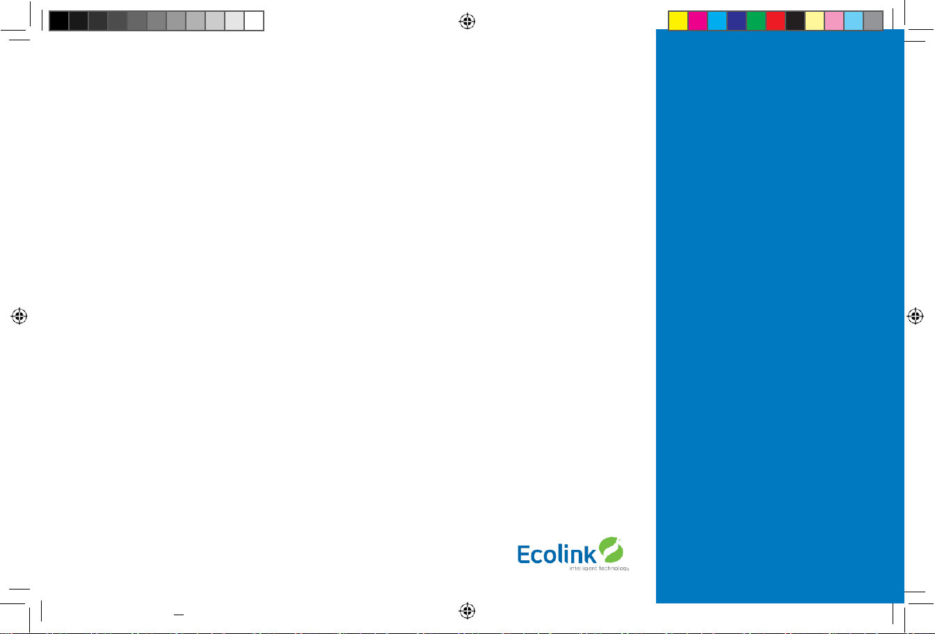
Box Contents
• 1 Z-Wave Thermostat
• 1 Sheet Adhesive Wiring Labels
• 2 Plastic Wall Anchors
• 2 Phillips Screws
• 4 AA Batteries
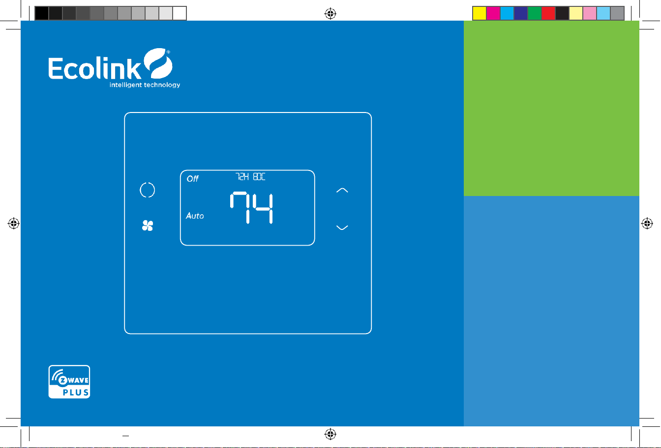
Figure 1.
Z-Wave Thermostat Front View
1x 4x 2x 2x
Page 5

24-02-2021 18:55
5
TBZ500 THERMOSTAT AT A GLANCE
This thermostat is compatible with most HVAC systems, including the following:
• 24VAC systems Note: requires both the 24VAC R and C (“common”) wires unless battery powered.
• Standard gas/oil/electric heating systems
- 1 stage heating and cooling
- 2 stage heating and cooling
• Heat Pump systems:
- 1 stage heating and cooling
- 2 stage heating and cooling
- 2nd or 3rd stage Auxiliary heating (heat strips)
• Do NOT use for systems with line voltage controls (120/240VAC) The thermostat can either be powered by batteries or
24VAC.
Battery Powered Operation
The thermostat can be powered by four AA Alkaline batteries. The thermostat will operate for approximately two years on four
AA Alkaline batteries depending on the frequency of user operations and backlight operation. Always use Alkaline batteries and
replace all four at the same time with NEW batteries.
Z-Wave Operation when Battery Powered
Important Note: If the thermostat is installed on a Z-Wave network, while it is battery powered, it does not work as a Z-Wave
repeater.
24VAC Powered Operation
Powering the thermostat with 24VAC power requires both the C wire (24VAC common wire - typically blue)
and the R wire (24VAC hot wire - typically Red). If the C wire is not available, then batteries are required.
Note! If the thermostat is powered from 24VAC, do not install batteries!
Z-Wave Operation when 24VAC powered
If the thermostat is installe
d on a Z-Wave network while it is 24VAC powered, it
operates as an always-on Z-Wave repeater.
Copyright © Ecolink Intellig ent Technology
TBZ500_manual_8_5x5_5_inch Combined_RDN1240221.indd 5
Page 6
TBZ500 24VAC OR BATTERY POWERED Z-WAVE THERMOSTAT
INSTALLATION INSTRUCTIONS
Installation Steps
• Remove old thermostat.
• Install TBZ500
• Set up the thermostat for the HVAC system
• Enroll on Z-Wave network
Remove Existing Thermostat
• Turn off power to the HVAC system.
Usually at the HVAC system or the circuit breaker panel.
• Remove cover of old thermostat to expose the wiring terminals.
• Take a picture of the wiring terminals! This will help with troubleshooting later if needed.
• Mark the wires attached to the terminals with the wiring labels included.
• Use the terminal labels and not the wiring color to mark the wires.
• Remove the old thermostat base.
• Caution! Do not let the wires slip into the wall.
NOTE: Taking a picture is critical if problems are encountered. This will allow reinstallation of the old thermostat
and will help with troubleshooting later if needed.
Terminal
Typical Wire Color
Function
Y YELLOW
Cool
W
WHITE
Heat
G GREEN
Fan
R RED
24VAC Return
C
BLUE
24V Common (typically BLUE). When the wire is present,
the thermostat can be powered without batteries.
When the wire is absent, the thermostat must be powered by batteries.
Copyright © E colink Intelligent Technology
TBZ500_manual_8_5x5_5_inch Combined_RDN1240221.indd 6 24-02-2021 18:55
6
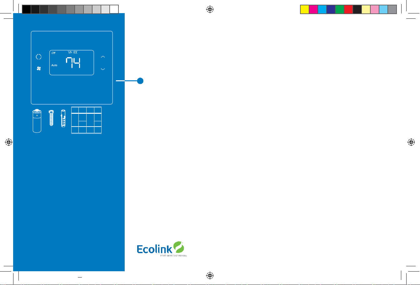
Old thermostat wiring terminals
*Note:
The C wire (24V common) may not be
present.
If C wire is not present, the TBZ500 must be
powered by batteries.
If the C wire is present, DO NOT INSTALL
BATTERIES in the TBZ500.
Mark the wires according to the terminal
markings. There may be additional wires
such as Y2, W2.
If y ou have RC and/or RH connections, see
below. Other wires are not used.
Heat Pump
Systems only
Page 7
Wiring Colors
While the thermostat terminal markings are intended to match the wire color, (R=RED, G=GREEN, W=WHITE, Y=YELLOW) be sure
to follow the terminal marking when marking the wires, even if the wire color doesn’t match.
WARNING: If the existing thermostat is a mercury-containing device, it must be disposed of in compliance with
federal, state, and local regulations. Many states and/or local agencies have collection or exchange programs or
hazardous waste collection programs for mercury containing devices.
For more information, see the U.S. Environmental Protection Agency website at:
http://www.epa.gov/osw/hazard/wastetypes/universal/mce.htm
For Canada: Environment Canada and Disposing of Mercury Products at:
https://www.ec.gc.ca/mer
cure- mer
cury/default.asp?lang=En&n=F111AAC6-1
Install the Back Panel
Remove the back panel of the thermostat by gently prying back panel from the thermostat.
• Mount the thermostat base to the wall using the wall anchors and screws provided.
• Level as needed.
• Connect the wires according to the HVAC system type as below.
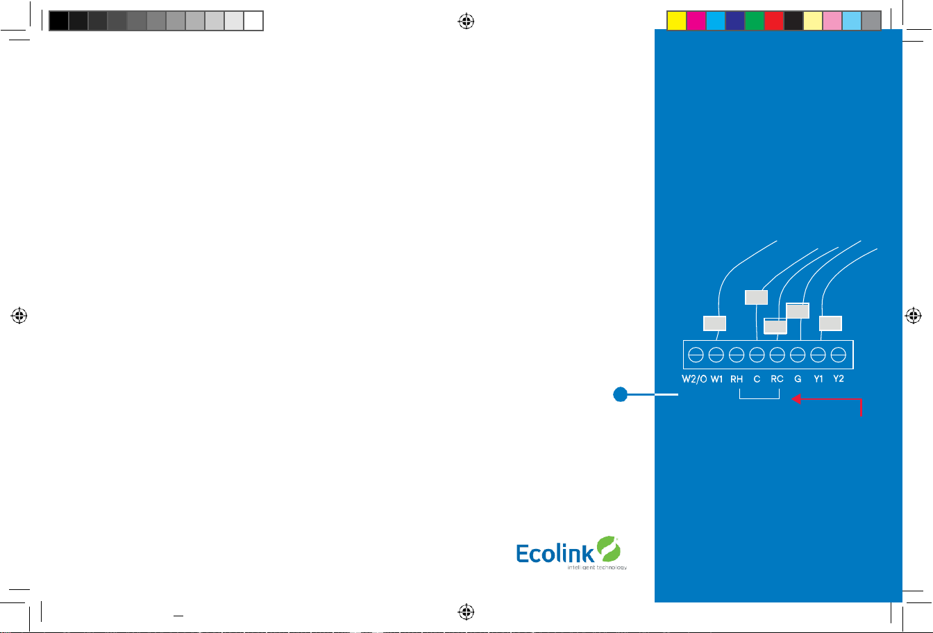
Standard Gas/Electric HVAC System Wiring
Single stage heating and cooling
R vs RC and RH Connections:
Single Transformer HVAC Systems.
Typical modern central HVAC installations have a integrated heating and cooling system with a single 24VAC transformer. For
these systems, there is only one 24VAC “R” wire and it can connect to either the RC or RH terminal on the thermostat. The
thermostat is supplied with an RC-RH jumper installed.
Do not remove the jumper for common transformer HVAC systems.
Copyright © Ecolink Intellig ent Technology
TBZ500_manual_8_5x5_5_inch
Combined_RDN1240221.indd 7 24-02-2021 18:55
R
G
C*
7
Factory insta lled RC and RH jumper
Connect the wires as marked from the HVAC
system to the corresponding terminals on
the thermostat back.
*C wire (24VAC common) may not be
present. If not, batteries must be installed.
Y W
Page 8
Orange White
Blue
Red
Green
Black/
brown
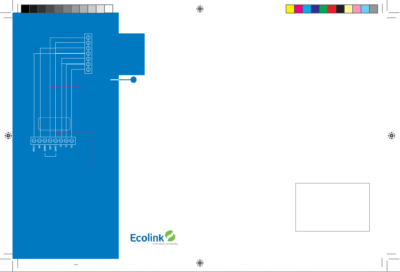
Separate Transformer HVAC Systems.
Some installations may have separate heating and cooling systems with separate 24VAC transformers. For those
systems there will be a separate “R” wire for the heating system (RH) and cooling system transformers (RC).
To c
onnect separate transformer systems, FIRST REMOVE THE SUPPLIED RH-RC JUMPER. Then
connect the heating “R” wire to the RH terminal and the cooling “R” wire to the RC terminal on the
thermostat.
Thermostat Setup:
Standard Gas/Electric HVAC Systems
• For Single Stage Heat/Cool Systems:
Go to the Menu screen by pressing and holding the FAN button for 5 seconds Press the down arrow to select
the SYSTEM menu and press Select.
Set the following:
• SYSTEM TYPE: Set to STANDARD
• FAN TYPE:
Set to
GAS
for typical gas furnace (fan is controlled by the furnace) Set to
ELECTRIC
for electric heat (fan on with heat call)
For Two Stage Heat/Cool Systems:
• Go to ADVANCED SYSTEMS SETTINGS menu.
• From the
Setup menu
screen, press and hold the Fan and Down arrow buttons for 5 seconds.
Use the Down arrow button to select the following:
- 2ND STAGE HEAT ENABLE:
Enable second stage heating output If a single stage heating system,
leave this set to N
If a 2 stage heating system, set to Y to enable.
- 2ND STAGE COOL ENABLE: Enable second stage cooling output
If a single stage cooling system, leave this set to N.
If a two stage cooling system, set to Y to enable.
Copyright © Ecolink Intellig ent Tech nology
TBZ500_manual_8_5x5_5_inch Combined_RDN1240221.indd 8 24-02-2021 18:55
mon
C 24VAC Com
R 24VA C Retu
Heat Stage 1
Heat Stage 2
G Fan
Y1 Compress
Y2 Compress
8
Factory installed RC/RH jumper
For single transformer systems, connect R wire
to either RC or RH terminal. They are connected
together by the factory installed jumper.
For systems with separate heating & cooling
transformers, connect Heating R to RH and
Cooling R to RC. NOTE! REMOVE THE FACTORY
INSTALLED RC/RH JUMPER.
C wire is not required
for battery operation.
C wire is required for
24VAC operation.
Yellow
Default Thermostat Setup:
•
Type: Standard HVAC
•
Fan Type: Gas Heat
•
1 Stage heatin g
•
1 Stage cooling
No Setup change required
for this configuration
Page 9
Wire Terminal
SINGLE AND DUAL TRANSFORMER SYSTEMS (SPLIT SYSTEMS)
HVAC systems may have one or two transformers. The “R” wire connects differently
depending on the system.
G
Connec t to the G terminal
C
Connec t to th e C terminal. C wire (24VAC common) may not be present. If not present,
batteries MUST be installed.
NOTES:
Ensure that the appropriate wires are screwed into the termin al blocks firmly. Gently pull on the wires to confirm
the connection. Push all excess wiring back into the wall opening.
Connect the wires from the HVAC system to the corresponding terminals on the thermostat back
terminal block. Use the table below as a guideline for connecting the wires.
Y or Y1 Connec t to the Y1 terminal
COOL Rc
Connec t to RC terminal
HEAT Rh
Connec t to RH ter minal
W2
Connec t to W2 terminal (2-stage system only)
IMPORTANT!:
for separate rc/rh sy stems, the internal rc=rh jumper must be cut on the back of the thermostat’s printed circuit board.
Single Transformer System
Most HVAC systems have a single 24VAC
transformer. For these systems, there is
only one “R” wire and it can be connected
to either the thermostat’s RC or RH
terminal as these are internally jumpered
together. If installing a Standard HVAC
system, connect the wires from the HVAC
system to the corresponding terminals
on the thermostat back terminal block.
Use the table below as a guideline
for connecting the wires.
Dual Transformer Systems
For HVAC systems that have separate
heating and cooling systems, each with
their own 24VAC transformers, there will
be an “R” wire from the heating system
and an “R” wire from the cooling system.
For dual transformer systems, connect
the “C” wire from the cooling system to
the thermostat’s “C” terminal.
DO NOT
CONNECT THE “C” WIRE FROM THE
HEATING SYSTEM.
Copyright © Ecolink Intelligent Technology 9
TBZ500_manual_8_5x5_5_inch
Combined_RDN1240221.indd 9 24-02-2021 18:55
W or W1
Connec t to W1 termin al
C
Connec t to C terminal (Cooling System C Wire, NOT Heatin g System C Wire)
G
Connec t to the G terminal
Connec t to the Y2 termin al (2-stage systems only)
Y2
W
Connec t to the W1 termin al
R
Connec t to either RC or RH terminals (Except for Dual Transformer Systems, See Next Page)
Connec t to the Y1 terminal
Y Terminal
Wire
Page 10
White
10
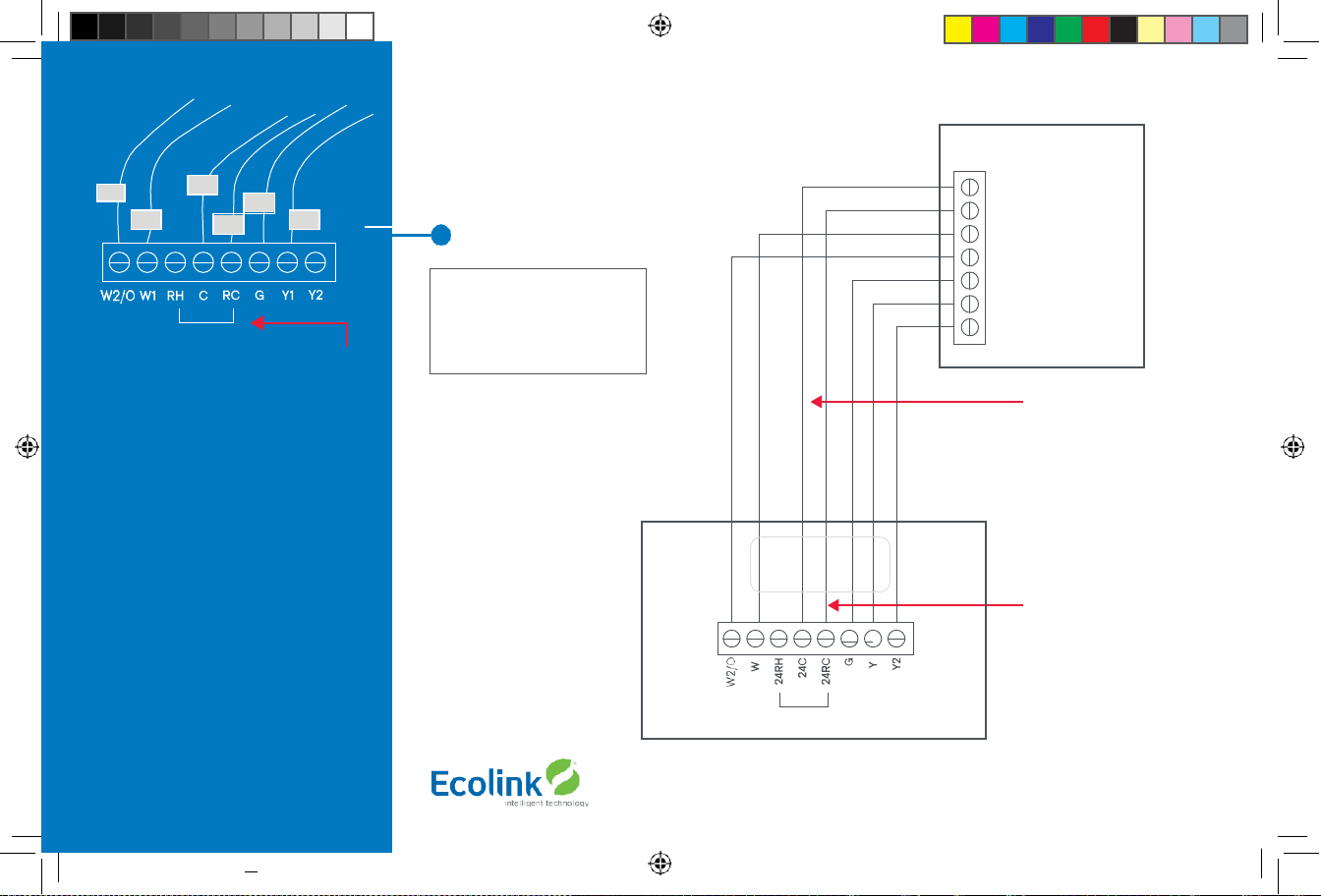
Heat Pump HVAC System Wiring
Single stage heating and cooling
Typical thermostat wiring colors.
Caution: verify that original wiring
matches. Colors may be different.
Blue
Red
Green
Yellow
Black/
brown
Heat Pump HVAC System
Thermostat connection
C 24VAC Common R
24VAC Return
W1 Aux Heat
O Changeover Valve
G Fan
Y1 Compressor Stage 1 Y2
Compressor Stage 2
Thermostat back
Factory installed RC/RH jumper
Most Heat Pump
systems have the C wire
and the thermostat can be
power by the 24VAC from
the HVAC system.
Batteries are not required
for 24VAC powered systems.
If there is not a C wire
installed, the thermostat
MUST be powered from
batteries.
Connect the R wire to either
the RC or RH terminal.
DO NOT REMOVE THE
RC/RH JUMPER
Copyright © Ecolink Intellig ent Tech nology
TBZ500_manual_8_5x5_5_inch Combined_RDN1240221.indd 10 24-02-2021 18:55
Y W
R
G
C*
Factory installed RC and RH jumper.
Do not re move
Connect the wires as marked from the HVAC
system to the corresponding terminals on
the thermostat back.
*C wire (24VAC common) Heat Pump
systems usually have the C wire connected
to the thermostat. If there isn’t a C wire,
batteries must be installed.
** O (Orange) or B (Brown) wire (changeover
valve) connect to the W2/O terminal on the
thermostat.
NOTE: Be sure to set the correc t changeover
operation (O = changeover with Cool, B =
changeover with Heat) in the SETUP menu.
Connect the R wire to either RC or
RH terminal.
Orange
Note!
If you get heating
when you expected cooling
or vice versa, change the
Change Over type to the
opposite setting.
O**
Page 11

24-02-2021 18:55
11
THERMOSTAT SETUP:
Heat Pump HVAC Systems
For Single Stage Heat/Cool Systems:
Go to the Menu screen by pressing and holding the FAN button for 5 seconds Press the down
arrow to select the SYSTEM menu and press Select. Set the following:
System type:
Set to HEAT PUMP
Change over:
For changeover with cooling systems (Orange wire): set to WITH COOL (most common and default setting) For
changeover with heating systems (Brown wire): set to WITH HEAT
You must configure the thermostat’s changeover valve setting to work correctly with your HVAC system.
Check your system information to be sure and note the color of original thermostat wire and the terminal it was connected to.
No matter what the old stat connection was (O or B), connect the wire to the thermostats W2/O terminal.
For Two Stage Heat/Cool Systems:
Go to ADVANCED SYSTEMS SETTINGS menu. From the Setup menu screen, press and hold the Fan and Down arrow buttons for
5 seconds. Use the Down arrow button to select the following:
Auxheat:
If you have auxiliary heat strips, set this to Y to enable. (Default is Y)
2nd stage head enable:
Enable second stage heating outputs If a single stage heating system,
leave this set to N. If a two stage heating system, set to Y to enable.
2nd stage cool enable:
Enable second stage cooling outputs If a single stage cooling system,
leave this set to N. If a two stage cooling system, set to Y to enable.
Copyright © Ecolink Intellig ent Technology
TBZ500_manual_8_5x5_5_inch Combined_RDN1240221.indd 11
Page 12

Install batteries
Watch polarity!
Finish Wiring
If you have additional wires for 2 stage systems (W2, Y2), see the wiring diagrams on page 5 and 6.
Check that the wires are screwed into the terminal blocks firmly. Gently pull on the wires to confirm
the connection. Push all the excess wiring back into the wall.
Mount the Thermostat
24VAC Powered Thermostat: If the thermostat is 24VAC powered (24VAC common “C” wire is connected), DO NOT INSTALL
BATTERIES!
• Install the thermostat on to the base.
• After all connections are made and thermostat is mounted, turn on power to the HVAC system/thermostat by either
re-energizing the circuit breaker in the breaker panel or by plugging in the HVAC system back in to the 120VAC wall outlet.
• Battery Powered Thermostat:
If the thermostat is battery powered (NO 24VAC common “C” wire connected), install 4 NEW
Alkaline AA batteries into the back of the thermostat.
• Install the thermostat on to the base.
• After all connections are made and thermostat us mounted, turn on power to the HVAC system/thermostat by either
re-energizing the circuit breaker in the breaker panel or by plugging in the HVAC system back in to the 120VAC wall outlet.
Copyright © Ecolink Intellig ent Tech nology
TBZ500_manual_8_5x5_5_inch Combined_RDN1240221.indd 12 24-02-2021 18:55
12
Page 13

THERMOSTAT SETUP: CONFIGURE FOR HVAC SYSTEM
The thermostat must be set up for the correct HVAC system type and configuration for proper operation.
Preset HVAC System settings
The thermostat is preset for the following typical HVAC system configuration:
• HVAC system type: Standard gas/electric
• HVAC fan type: Gas heat
• HVAC heating stages: one
• HVAC cooling stages: one
If the thermostat is installed on this type HVAC system, the System setup does not need to be changed.
Installation is complete
For thermostats installed on a Heat Pump HVAC system or any HVAC configuration other than the preset settings, the System
settings need to be changed in the SYSTEM setup menu to match the HVAC system.
Changing the HVAC System Setup
To change the thermostats HVAC system settings, first select the Menu Screen and then select the SYSTEM menu. Follow
instructions below to access the SYSTEM menu.
Entering Menu Mode
To change the System setup, go to the thermostats Menu Mode a
nd select SYSTEM. From there select the correct HVAC se
tting
s
t
o match the installati
on type. Press a
nd hold the FAN button to enter the Me
nu Mode. SETUP is the first menu item displayed
.
Press the down button to advance to the SYSTEM screen.
Note:
To conserve battery life, the thermostat
backlight turns off after a short time of
no activity.
The first press of any button will turn
on the backlight but will not initiate
any action other than turning on the
backlight. Press the button again to
initiate the action desired. If the backlight
is already on, button presses work with
the first press.
Copyright © Ecolink Intelligent Technology 13
TBZ500_manual_8_5x5_5_inch
Combined_RDN1240221.indd 13 24-02-2021 18:55
Page 14

Menu choices are displayed in
the Status Display Line.
Press
“Select”
to enter the
selected menu
Press
“Done”
to exit back to
the Main Thermostat Screen
Use the Up/Down buttons to
change to the desired menu item,
then press
“Select”
Not sure which Changeover type?
Check the existing thermostat conne ctions
to help determine this.
•
If the origina l syste m had an orange wire
connected to the
“O” terminal, then this
is a
“changeover with cool”
system.
•
If there was a brown wire connecte d to
the
“B”
terminal, then this is a
“change
over with heat”
system.
•
Set the Change Over setting accordingly.
(Caution: These are typical wiring colors/
connections and may differ)
• If heating comes on when cooling is
expected or vice versa, change the
“Change Over Type”
to the opposite
setting.
14
Thermostat Menu Screen
Menu Mode Navigation
When the thermostat Menu Screen is displayed, use the
Up or Down arrow buttons to scroll through the following
options:
• Setup
(user preference settings)
• System
(HVAC system setup)
• Zwave
(install/uninstall from Z-Wave network)
• Info
(firmware versions and Z-Wave network
information)
Select SYSTEM setup
To change the HVAC system default settings, use the down
arrow to progress to the SYSTEM menu item and press
“Select”.
SYSTEM setup menu
The SYSTEM menu is used to set up the thermostat for the
correct HVAC system type.
• System type
- For Standard Gas/Electric systems, select “Standard”.
This is the default setting.
- For Heat Pump systems, use the Up/Dn arrows to
change to “Heat Pump”
- Press Select to set.
- Press Done to exit
• Fan type (For Standard HVAC systems only)
- Fan type depends on the heating system type.
- For Gas heat: select “GAS”. This is the default setting.
- For Electric heat: use the Up/Dn arrows to change to
“ELECTRIC”.
- Press Select to set
- Press Done to exit
• Changeover type (For Heat Pump HVAC systems only)
The changeover (or reversing) valve is used to change from
heating to cooling operation. It is either a changeover with
cooling type (Orange wire) or changeover with heating
type (Brown wire). Most are changeover with cooling, which
is the default setting.
- For Changeover with Cooling systems (Orange wire),
select “WITH COOL”. This is the default setting.
- For Changeover with Heating systems (Brown wire),
use the Up/Dn arrows to change to “WITH HEAT”.
- Press Select to set
- Press Done to exit
Copyright © Ecolink Intellig ent Tech nology
TBZ500_manual_8_5x5_5_inch Combined_RDN1240221.indd 14 24-02-2021 18:55
Page 15

24-02-2021 18:55
15
ADVANCED SYSTEM SETTINGS MENU
The Advanced System Settings Menu provides for addition system setup options. These settings can affect system operation
and should only be changed by qualified HVAC installers.
• To access the Advanced System Settings menu, first press and hold the Fan button to get to the MENU screen. Continue to
hold down the Fan button and press and hold the Down Arrow button for 5 seconds.
• The first menu item in the Advance System Settings menu “Display Lock”, will be displayed. Use the Up/Down arrow buttons
to scroll through the menu options to the desired setting.
• Press “Select” (Mode) button to change a setting. Once it begins to flash, use the Up/Down buttons to select the desired
setting.
• Press the SELECT button to accept the new setting (flashing will stop).
Copyright © Ecolink Intelligent Techn ology
TBZ500_manual_8_5x5_5_inch Combined_RDN1240221.indd 15
Feature
Description
Range Default
Setting
Display Lock
Allows the thermosta t buttons to be locked. When the buttons are locked, none
of the thermostat buttons will function as normal. To unlock the thermostat
when Display Lock is enabled, press and hold the FAN button for 5 seconds to
access the Setup screen (it’s the only button that works in the lock mode). Access
the Advanced Settings Menu (as above) to turn the Display Lock off.
Y or N N
Test Mode
Test mode shortens th e system built-in delays (like MOT and MRT)
Y =
Test mode on. Reduces all delays to 10 seconds
for quicker system testin g
N =
Test mode off. Normal system delays
Y or N N
Aux Heat Enable
(Heat Pump Sys-
tems only)
**Becomes availab le when System Type: Heat Pu mp is selected in standard menu.
Enables the auxiliary heat o peration.
Typicall y the au xiliary heat will be heat-strips in a heat pump system.
Y or N Y
2nd Stage Heat
Enable
Enables the second stage heat operation
Y or N Y
2nd Stage Cool
Enable
Enables the second stage cool operation
Y or N Y
Minimum run
time
Sets the Minimum Run Time (MRT) delay before a heating/cooling cycle can turn
off.Sets heating/coolin g cycle time. Preven ts rapid on/off cycling.
1-9
3
Page 16

Feature
Description
Range
Default
Setting
Minimum Off time
Sets the Minimu m Off Time (MOT) delay before another heating/cooling cycle
can begin. Provides compressor short cycle protection. “Wait” is displayed on
screen when active.
5-9 Minutes
5
Heat Setpoint
Max.
Sets the maximum heating setpoint value.
Will not ramp or accept setpoints higher than this maximum
55F to 96F (4C
to 43C)
90F (32C)
Cool Setpoint Min.
Sets the minimum cooling setpoint value
60F to 99F
60F (15C)
(6C-45C)
Heat Blower Off
Sets the system blower delay off time after a heat call ends (fan purge)
0 to 9 seconds
0 (off)
Delay
Cool Blower Off
Sets the system blower delay off time after a cool call ends (fan purge)
0 to9 seconds
0 (off)
Delay
Heat - Cool Delta
Sets the minimum separation between heatin g and cooling setpoints.
Note:
3 to 15
3F (1C)
Attempts to lower cooling setpoint below the heating setpoint will PUSH the
degrees
heating setpoint down to maintain this separation. The same applies to setting
the heating setpoint above the cooling setpoint, it will PUSH the cooling set-
point up to maintain the setpoint delta separation
Heating Stage 1 on Sets the delta from setpoint that stage 1 heating starts
1 to 6 degrees
1
Threshold
Heating Stage 1
Sets the delta from setpoint that stage 1 heating stops. Stage 1 turns off at
0 to 5 degrees
0
Off Threshold
setpoint + Delta Stage 1.
Heating Stage 2 Sets the delta from setpoint that stage 2 heating starts
2 to 7 degrees
2
On Threshold
Heating Stage 2
Sets the delay from setpoint that stage 2 heating stops. Stage 2 turns off at
0 to 6 degrees
0
Off Threshold
setpoint + Delta Stage 2.
Aux Heat On Sets the delta from setpoint that stage 3 heating starts
3 to 8 degrees
3
Threshold
Aux Heat Off Sets the delta from setpoint that stage 3 heating stops.
0 to 7 0
Threshold
Stage 3 turns off at setpoint + Delta Stage 3
degrees
Cooling Stage 1 Sets the delta from setpoint that stage 1 cooling starts.
1 to 7 1
On Threshold
degrees
Copyright © Ecolink Intellig ent Tech nology
TBZ500_manual_8_5x5_5_inch Combined_RDN1240221.indd 16 24-02-2021 18:55
16
Page 17

24-02-2021 18:55
17
Feature
Description
Range
Default
Setting
Cooling Stage 1
Off Threshold
Sets the delta from setpoint that stage 1 cooling stops. Stage 1 turns off at
setpoint - Delta Stage 1
0 to 6 degrees
0
Cooling Stage 2
On Threshold
Sets the delta from setpoint that stage 2 cooling starts.
2 to 8 degrees 2
Restore Defaults Restores all settings to factory defaults. Press Yes to restore defaults
Press No to exit and not restore defaults
Y or N
N
Factory Default
Please use this procedure only when the Z-Wave Primary Controller is missing or otherwise inoperable. To reset the
TBZ500’s Z-Wave parameters to Factory Settings (both Z-Wave and HVAC settings):
1. Remove power from the TBZ500.
2. Restore power to the TBZ500.
3. When “TBZ500” appears on the screen, hold down the MODE and FAN buttons at the same time.
4. Release the buttons when RESET appears on the Status Line.
5. Once the TBZ500 resets the Z-Wave and HVAC settings, a DONE confirmation message will appear on the screen before the thermostat self-reboots.
Copyright © Ecolink Intelligent Techn ology
TBZ500_manual_8_5x5_5_inch Combined_RDN1240221.indd 17
Cooling Stage 2
Off Threshold
Sets the delta from setpoint that stage 2 cooling stops.
Stage 2 tu rns off at setpoint - Delta Stage 2.
0 to 7 degrees
0
Page 18

Z-Wave Installation
Adding the thermostat to a Z-Wave network.
6. Follow the instructions provided with your system for enrolling the thermostat.
7. Press and hold the FAN button on the Thermostat until the screen changes to the Menu screen.
8. Press the UP button until ZWAVE is shown in the Status Display line then press Select.
9. INSTALL should be shown on the status line.
10. When instructed by your system installation to add the thermostat to the network press the “Select” button to install.
Wait until SUCCESS or FAILED is shown on thestatus
display.
11. Press Done on the Thermostat to exit the ZWAVE screen.
12. Press Done on the Thermostat again to exit the Menu screen.
13. Once enrolled on your system’s network, continue to follow the instructions provided to complete the enrollment and
naming of the thermostat.
14. The
indicator should be shown on the Thermostat Main screen indicating the thermostat has successfully been
enrolled into the Z-Wave network.
Removing the thermostat from a Z-Wave network.
It may be necessary to remove and/or reinstall the thermostat from a Z-Wave network if the thermostat has been previously
installed on another network. Follow the instructions supplied with your Z-Wave system to remove/uninstall a Z-Wave device.
When the system instructs you to press and release the Z-Wave button on the thermostat, follow these steps:
1. Press and hold the FAN button for 3 seconds until the Menu screen is displayed.
2. Press the UP arrow button to scroll to the “ZWAVE” menu.
3. Press “Select” to select the ZWAVE screen.
4. The display will show “REMOVE” in the text line.
5. Press “Select” to perform the remove action.
6. “WAIT” will be displayed in the text line. The remove operation is in process.
7. “SUCCESS” will be display when the thermostat has been excluded from the network.
8. Press “Done” to exit back to the thermostat screen.
9. Thermostat is now ready to be added to any Z-Wave network.
Copyright © Ecolink Intellig ent Tech nology
TBZ500_manual_8_5x5_5_inch Combined_RDN1240221.indd 18 24-02-2021 18:55
18
Page 19

Fan Mode indicators
System Mode indicators
TBZ500 24VAC OR BATTERY POWERED Z-WAVE THERMOSTAT
OPERATION INSTRUCTIONS
Backlight and Button Operation
The thermostat backlight is normally set to go out after 10
seconds of no button presses to conserve battery power. If
the backlight is off, the first button press of any button will
only turn on the backlight. Once the backlight is on, the
buttons function normally.
System Operation Modes
displayed = System is ON and heating.
If flashing, minimum run time (MRT) is active
displayed = System is ON and cooling.
If flashing, minimum run time (MRT) is active
Stage Indicators
• “1” = Stage 1 heating or cooling is ON
• “2” = Stage 2 heating or cooling is ON
• “3” = Stage 3 heating (Aux Heat) is ON
For Heat Pump systems only:
• “Heat-E” = Emergency heat mode active
Copyright © Ecolink Intellig ent Technology
TBZ500_manual_8_5x5_5_inch
Combined_RDN1240221.indd 19 24-02-2021 18:55
TBZ500 Display
19
Text Information Display Line
Low Battery indicator
Display Lock indicator
Z-Wave Network Installed indicator
Heating/Cooling Mode Selection
Button Mode Status
Backlit Display
Text Display Line
Temperature Setting Touch Buttons:
Warmer
Room Temperature
Cooler
Fan Mode Selection
Page 20

SETTING THE SYSTEM MODE
Press MODE
button to change
system mode
System Modes
• Off:
System is off. No heating or cooling will come on. If system was on, it will turn off immediately.
• Heat:
Only heating will occur.
• Cool:
Only cooling will occur.
• Auto:
Heating or cooling will come on according to the heating and cooling setpoints. The system will
automatically switch between heating and cooling modes as needed to maintain the setpoints.
• Special Heat Pump Mode:
Emergency Heat.
• Heat-E:
An additional system mode, “Heat-E” for Emergency Heat will be displayed if the HVAC System Type is set to Heat
Pump. If there is a compressor failure with the Heat Pump system, setting the mode to Emergency Heat will allow the
supplemental Aux Heat to come on first whenever there is a call for heating. It also disables the compressor output to
prevent further damage to the HVAC system.
Caution!
Emergency Heat should only be used for emergencies until the HVAC system can be repaired. Running the system in
Emergency Heat mode is commonly the most expensive mode since only the electric heat strips are bei ng used instead of the
more efficient heat pump compressor.
20
Copyright © Ecolink Intellig ent Tech nology
TBZ500_manual_8_5x5_5_inch Combined_RDN1240221.indd 20 24-02-2021 18:55
Page 21

SETTING THE HEATING OR COOLING TEMPERATURE SETPOINT
Setpoint Change
To change the setpoint, press the Up or Down arrow buttons. The screen will switch to the setpoint change screen (as above)
and show the current setpoint of the current heating or cooling mode. Adjust setpoint temperature up or down with the arrow
buttons.
Note! When in the Setpoint Change screen, pressing the MODE button will switch the setpoint being displayed between
the Heat and Cool setpoints.
Setpoint Push:
The cooling setpoint cannot be set below the heating setpoint. The thermostat will “push” the heating setpoint
lower if the cooling setpoint is set below the current heating setpoint. A 3 degree separation is maintained between the heating
and cooling setpoints. The same is true for raising the heating setpoint above the cooling setpoint. The thermostat will “push”
the cooling setpoint up to maintain the 3 degree separation.
Setpoint being
changed
Press MODE button to
change from the heat
setpoint to the cool
setpoint
Press “Done” (FAN button)
to set the setpoint and exit
back to the main thermostat
screen or wait for the screen
to automatically time out.
Copyright © Ecolink Intellig ent Technology
TBZ500_manual_8_5x5_5_inch
Combined_RDN1240221.indd 21 24-02-2021 18:55
21
Lower Temperature
Pressing the Up or Down buttons
will change the setpoint 1 degree. Press
and hold the button to
ramp the setpoint.
Raise Temperature
Press the Up or Down arrow buttons to
set the desired temperature setpoint
Press either Up or Down
arrow button to go to
the Setpoint Change
screen
Page 22

Use the UP/DOWN bu ttons to
select the desired menu item
SETTING THE FAN MODE
Fan Modes
• Auto:
Fan automatically operated by the HVAC system. (normal setting)
• On:
Manual Fan mode. Fan stays on until mode is changed back to Auto,independent of the heating or cooling system
operation.
THERMOSTAT MENU MODE
The Thermostat has a menu of setup and information
displays. To change to the Me
nu Mode, press a
nd hold th
e
FAN button for 5 seconds. The display will change to the
Menu Mode and display the Setup screen. Use the Up/
Down arrow buttons to scroll through other menu items.
Press and hold the FAN button for 5 seconds to go to
the
Menu Mode screen
Copyright © Ecolink Intellig ent Tech nology
TBZ500_manual_8_5x5_5_inch Combined_RDN1240221.indd 22 24-02-2021 18:55
22
Press “Done” to go back to the
Thermostat Main Screen
Menu item display
Press “Select” to go to the
selected menu item screen
Press the FAN button to
change the Fan mode
Page 23

SETUP menu
User preference settings.
• Fahrenheit or Celsius.
Select the temperature display mode.
• Backlight timeout.
Sets the time from last button press that the backlight will turn off. Range: 10 (default) -30 seconds. Note: long backlight
timeouts will reduce battery life. If the thermostat is powered from 24VAC, the backlight timeout can be set to “0” which wil l
keep the backlight on continuously.
• temperature sensor calibration.
Change the temperature calibration by +/- 7 degrees. Use the Up/Down arrow buttons to change to the desired temperature
displayed.
• Status Line Display.
Select Setpoints or Relative Humidity to be displayed on the upper status line.
SYSTEM menu
• System type
Select the system type, STANDARD or HEAT PUMP TYPE (Standard systems only).
• Select fan type:
gas
(typical default setting) or
electric
• Change over type
(Heat Pump systems only).
Select the Changeover type: Changeover WITH COOL (typical default setting) or Changeover WITH HEAT.
Z-WAVE menu
This menu item allows the thermostat to be enrolled to the Z-Wave network. Follow the instructions shown
in the Z-Wave® Operation section (page 18) to enroll the Thermostat onto the network.
INFO menu
The INFO menu displays information about the thermostat. Use the Up/Dn buttons to scroll through the
various items.
Menu Mode Screen
• Setup
(user preference settings)
• System
(HVAC system setup)
• Zwave
(Z-Wave network install or
remove)
• Info
(Displays thermostat version
and setup info)
Thermostat information displayed:
• Version:
Thermostat firmware
version
• Zwave:
Z-Wave firmware
version
• Node ID:
Z-Wave Node ID
• Home ID:
Z-Wave Home ID
• System type:
displays current
System Type settings (Standard or
Heat Pump)
• If System Type =
Standard
FAN TYPE displays current Fan Type
setting
• If System Type =
Heat Pump
CHANGEOVER TYPE displays current
Change Over valve (reversing valve)
setting
• AC or Battery Powered:
AC POWER
will be displayed if power by 24VAC
Copyright © Ecolink Intelligent Technology 23
TBZ500_manual_8_5x5_5_inch
Combined_RDN1240221.indd 23 24-02-2021 18:55
Page 24

THERMOSTAT OPERATION
Minimum Run Time (MRT)
The thermostat has a Minimum Run Time (MRT) delay after the start of any heating or cooling call. This minimum run time assures
even heating and cooling cycles. The MRT will keep the system on, even if it reaches the setpoint room temperature, or you
change the setpoint to a temperature that would satisfy the call, until the MRT expires. Changing the Mode to OFF will cancel
the MRT and the system will turn off immediately. The MRT can be adjusted in the Advanced Settings menu of the thermostat.
Note:
When MRT is active, the heating or cooling icon will be flashing.
Minimum Off Time (MOT)
The thermostat has a Minimum Off Time (MOT) delay after any heating or cooling cycle ends. This delay prevents rapid heating/
cooling cycles and also provides “short cycle protection” for the system compressor. This delay may be noticeable when you
change a setpoint and it does not respond immediately due to the MOT delay timer preventing the system from restarting. The
MOT delay time can be adjusted in the Advanced Settings menu of the thermostat but there is a minimum of a 5 minute delay
to assure compressor protection.
Note:
When MOT is active, the thermostat Status Display shows “WAIT”.
Z-WAVE® OPERATION
Thermostat Battery Operation:
If the thermostat is installed in a Z-Wave network while powered by batteries, it will be enrolled
as a Z-Wave FLiRs type device. This is a power saving mode that conserves the batteries by keeping the radio asleep most of the
time. However, in this mode, the thermostat does not act as a repeater/router in the Z-Wave network.
Thermostat 24VAC Operation:
If the thermostat is installed in a Z-Wave network while powered by 24VAC, it will be enrolled as
an always-listening device and can act as a router node in the Z-Wave network.
Caution!
Once installed in a Z-Wave network, if you change how the thermostat is powered (from batteries to 24VAC or vice
versa), you must remove and re-enroll the thermostat in the Z-Wave network for it to work correctly.
Copyright © Ecolink Intellig ent Tech nology
TBZ500_manual_8_5x5_5_inch Combined_RDN1240221.indd 24 24-02-2021 18:55
24
Page 25

24-02-2021 18:55
25
SmartStart Inclusion – Adding the thermostat to a Z-Wave Network
The TBZ500 is SmartStart enabled and can be added into a Z-Wave network by scanning the Z-Wave QR Code present on
the product with a controller providing SmartStart inclusion. No further action is required and the SmartStart product
will be added automatically within 10 minutes of being switched on in the network vicinity. The SmartStart QR code can
be found on the back of the thermostat, side of the package, or also inserted as an insert card/sticker. The sticker
contains the full DSK string. It’s important that if you plan to use DSK that you keep this label in a safe place you’ ll
remember. If your system does not support SmartStart, you can still enroll your thermostat using classic inclusion.
Classic Inclusion - Adding the thermostat to a Z-Wave network.
1. Follow the instructions provided with your system for enrolling the thermostat.
2. Press and hold the
FAN button
on the Thermostat until the screen changes to the Menu screen.
3. Press the UP button until ZWAVE is shown in the Status Display line then press Select.
4. INSTALL should be shown on the status line.
5. When instructed by your system installation to add the thermostat to the network press the “Select” button to install.
Wait until SUCCESS or FAILED is shown on thestatus display.
6. Press Done on the Thermostat to exit the ZWAVE screen.
7. Press Done on the Thermostat again to exit the Menu screen.
8. Once enrolled on your system’s network, continue to follow the instructions provided to complete the enrollment and
naming of the thermostat.
9. The
indicator should be shown on the Thermostat Main screen indicating the thermostat has successfully been
enrolled into the Z-Wave network.
Removing the thermostat from a Z-Wave network.
It may be necessary to remove and/or reinstall the thermostat from a Z-Wave network if the thermostat has been previously
installed on another network. Follow the instructions supplied with your Z-Wave system to remove/uninstall a Z-Wave device.
When the system instructs you to press and release the Z-Wave button on the thermostat, follow these steps:
1. Press and hold the FAN button for 3 seconds until the Menu screen is displayed.
2. Press the UP arrow button to scroll to the “ZWAVE” menu.
3. Press “Select” to select the ZWAVE screen.
4. The display will show “REMOVE” in the text line.
5. Press “Select” to perform the remove action.
6. “WAIT” will be displayed in the text line. The remove operation is in process.
7. “SUCCESS” will be display when the thermostat has been excluded from the network.
8. Press “Done” to exit back to the thermostat screen.
9. Thermostat is now ready to be added to any Z-Wave network.
Copyright © Ecolink Intellig ent Technology
TBZ500_manual_8_5x5_5_inch Combined_RDN1240221.indd 25
Page 26

Z-WAVE COMMAND CLASSES
Z-Wave Command Classes
TBZ500
COMMAND_CLASS_BASIC
•
COMMAND_CLASS_ZWAVEPLUS_INFO_V2
•
COMMAND_CLASS_ANTITHEFT_V2
•
COMMAND_CLASS_ASSOCIATION_GRP_INFO
•
COMMAND_CLASS_ASSOCIATION_V2
•
COMMAND_CLASS_BATTERY
•
COMMAND_CLASS_DEVICE_RESET_LOCALLY
•
COMMAND_CLASS_FIRMWARE_UPDATE_MD_V2/V3
•
- V3
COMMAND_CLASS_MANUFACTURER_SPECIFIC_V2
•
- V2
COMMAND_CLASS_MULTI_CMD
•
COMMAND_CLASS_POWER_LEVEL
•
COMMAND_CLASS_SENSOR_MULTILEVEL_V5
•
- V5
COMMAND_CLASS_THERMOSTAT_FAN_MODE
•
COMMAND_CLASS_THERMOSTAT_FAN_STATE
•
COMMAND_CLASS_THERMOSTAT_MODE_V3
•
- V3
COMMAND_CLASS_THERMOSTAT_OPERATING_STATE_V2
•
- V2
CCOMMAND_CLASS_THERMOSTAT_SETPOINT_V2/V3
•
- V3
COMMAND_CLASS_VERSION_V2
•
COMMAND_CLASS_SECURITY_2
•
COMMAND_CLASS_TRANSPORT_SERVICE_V2
•
COMMAND_CLASS_SUPERVISION
•
COMMAND_CLASS_CONFIGURATION_V2
•
- V2
Copyright © Ecolink Intellig ent Tech nology
TBZ500_manual_8_5x5_5_inch Combined_RDN1240221.indd 26 24-02-2021 18:55
26
Page 27

24-02-2021 18:55
27
Association groups
The TBZ500 supports 3 groups and 5 associations per group.
Group 1 Association Alerts are to notify an associated device of a thermostat generated change. Thermostat generated changes are those
changes that originate at or by the thermostat. The general classifications of thermostat generated changes are:
• User interface changes – Setpoints, Mode, Fan Mode, Occupied Mode
• Operational changes – Operating State, Fan State (See Configuration parameter #24 for details)
• COMMAND_CLASS_CONFIGURATION changes – See the COMMAND_CLASS_CONFIGURATION table for additional unsolicited alerts
• Setpoint Push – When a setpoint is pushed to maintain the HC-Delta separation
• Battery Status when the battery reaches the predefined thresholds
Group 2 Association Alerts will send a BASIC_SET 0xFF when a Cool Call starts and a BASIC_SET 0x00 when the Cool Call ends
Group 3 Association Alerts will send a BASIC_SET 0xFF when a Heat Call starts and a BASIC_SET 0x00 when the Heat Call ends
TBZ500_manual_8_5x5_5_inch Combined_RDN1240221.indd 27
Page 28

Z-Wave Configurations
There are configuration parameters accessible via the COMMAND_CLASS_CONFIGURATION.
Note all temperature related parameters are in degrees F.
Config
Parameter
#
Description
Length
(bytes)
Send
Unsolicited
on change
Default
Value
Read values
Write values
1
System Type 4
1 N 0
0 = Standard 1 = Heat Pump
0 = Standard 1 = Heat Pump
2
Fan Type 4
1 N 0
0 = Gas (No fan w/Heat) 1 =
Electric (Fan w/Heat)
0 = Gas (No fan w/Heat), 1 =
Electric (Fan w/Heat)
3
Change Over Type 4
1 N 0
0 = CO w/cool 1 = CO w/heat
0 = CO w/cool 1 = CO w/heat
4
2nd Stage Heat Enable 4
1 N 0
0 = Disabled
1 = Enabled
0 = Disabled
1 = Enabled
5
Aux Heat Enable 4
1 N 1
0 = Disabled
1 = Enabled
0 = Disabled
1 = Enabled
6
2nd Stage Cool Enable 4
1 N 0
0 = Disabled
1 = Enabled
0 = Disabled
1 = Enabled
7
C/F Type
1 N 1
0 = Centigrade
1 = Fahrenheit
0 = Centigrade
1 = Fahrenheit
8
MOT 5
1 N 5
5-9
5-9 9 MRT 5
1 N 3
3-9
3-9
10
Setpoint H/C Delta
1 N 3
3-15
3-15
11
H Delta Stage 1 ON
1 N 1
1-6
1-6
12
H Delta Stage 1 OFF
1 N 0
0-5
0-5
13
H Delta Stage 2 ON
1 N 2
2-7
2-7
14
H Delta Stage 2 OFF
1 N 0
0-6
0-6
15
H Delta Aux ON
1 N 3
3-8
3-8
16
H Delta Aux OFF
1 N 0
0-7
0-7
17
C Delta Stage 1 ON
1 N 1
1-6
1-6
Page 29

Config
Parameter
#
Description
Length
(bytes)
Send
Unsolicited
on
change
Default
Value
Read values
Write values
18
C Delta Stage 1 OFF
1 N 0
0-5
0-5
19
C Delta Stage 2 ON
1 N 2
2-7
2-7
20
C Delta Stage 2 OFF
1 N 0
0-6
0-6
21
Mechanical Status 3
2 Y
MECH_H1 0x0001
MECH_H2 0x0002
n/a
0x15
MECH_H3 0x0004
MECH_C1 0x0008
MECH_C2 0x0010
PHANTOM_F 0x0020
MECH_F 0x0040
MANUAL_F 0x0080
Reserved 0x0100
22
SCP Status 3 1 Y
STATE_HEAT 0x01
STATE_COOL 0x02
n/a
0x16
STATE_2ND 0x04
STATE_3RD 0x08
STATE_FAN 0x10
STATE_LAST 0x20
STATE_MOT 0x40
STATE_MRT 0x80
23
Autosend Enable Bits
2 N
0x205F
TEMPERATURE
(CC_SENSOR_MULTILEVEL)
0x0001
0x17
SETPOINTH
(CC_THERMOSTAT_SETPOINT)
0x0002
When set, the
corresponding
SETPOINTC
(CC_THERMOSTAT_SETPOINT)
0x0004
report is sent out
unsolicited
MODE
(CC_THERMOSTAT_MODE)
0x0008
when a changed is
detected, to
FANMODE
(CC_THERMOSTAT_FAN_MODE)
0x0010
the nodes in the
association list
FANSTATE (CC_THERMOSTAT_FAN_STATE) 0x0020
OPERATINGSTATE (CC_THERMOSTAT_OPERATING_STATE) 0x0040
SCHEDENABLE (CC_CONFIGURATION #38) 0x0080
SETBACK (CC_CONFIGURATION #40) 0x0100
RUNHOLD (CC_CONFIGURATION #39) 0x0200
DISPLAYLOCK (CC_CONFIGURATION #24) 0x0400
0x0800
0x1000
BATTERY
6
(CC_BATTERY) 0x2000
MECH STATUS (CC_CONFIGURATION #21) 0x4000
SCP STATUS (CC_CONFIGURATION #22) 0x8000
24
Display Lock 3
1 Y 0
0 = unlocked
0 = unlocked
1 =locked
1 = locked
Page 30

Config
Parameter #
Description
Length
(bytes)
Send
Unsolicited on
change
Default
Value
Read values
Write values
26
Backlight Timer
1 N 20
10-30
10-30
33
Max Heat Setpoint
1 N 90
30F – 109F
30F – 109F
34
Min Cool Setpoint
1 N 60
33F – 112F
33F – 112F
38
Schedule Enable
1 N 0
0 = Disabled
1 = Enabled
0 = Disabled
1 = Enabled
40
Setback Mode 3
1 Y 0
0 = No Setback
2 = UnOccupied Mode
0 = No Setback
2 = UnOccupied Mode
41
Un-Occupied HSP 1
1 N 62
30F - 109F
30F - 109F
42
Un-Occupied CSP 1
1 N 80
33F – 112F
33F – 112F
43
Remote Sensor 1 Node Number
1 N 0
0-252
0= Disabled
0-252
0= Disabled
46
Remote Sensor 1 Temperature
1 N 0 n/a
48
Internal Sensor Temp Offset
1 N 0
-7 to 7
-7 to 7
49
R1 Sensor Temp Offset
1 N 0
-7 to 7
-7 to 7
52
Filter Timer (hours)
2 N 0
0-4000+
0-4000
53
Filter Timer Max (hours)
2 N 300
0-4000
0-4000
54
Heat Timer (hours)
2 N 0
0-4000+
0-4000
55
Cool Timer (hours)
2 N 0
0-4000+
0-4000
61
Fan Purge Heat
1 N 0
0-90
0-90
62
Fan Purge Cool
1 N 0
0-90
0-90
170
0xaa
Send Association Autosend with ACKs
1 N 1
0 = Send with no ACK request 1 = Send
with ACK request
0 = Send with no ACK request 1 = Send
with ACK request
171
0xab
Number of Heat Call Starts
4 N 0
0-0x7FFFFFFF
0-0x7FFFFFFF
172
0xac
Number of Cool Call Starts
4 N 0
0-0x7FFFFFFF
0-0x7FFFFFFF
173
0xad
Reboot Count
4 N 0
0-0x7FFFFFFF
0-0x7FFFFFFF
174
0xae
CPU runtime (sec) (battery mode
only)
4 N 0
0-0x7FFFFFFF
n/a
175
0xaf
Autosend Wakeup count
4 N 0
0-0x7FFFFFFF
0-0x7FFFFFFF
Page 31

Config
Parameter #
Description
Length
(bytes)
Send
Unsolicited on
change
Default
Value
Read values
Write values
176
0xb0
UI Wakeup count
4 N 0
0-0x7FFFFFFF
0-0x7FFFFFFF
177
Reserved
178
0xb2
Power Status
Bits are set according to power setup.
1
POWER_BATTERY 0x01 POWER_24VAC
0x02
PWR_ACINSTALL 0x10
PWR_BATINSTALL 0x20
PWR_FLIRS 0x40
n/a
179
0xB3
Battery Bank Voltage (%)
1 N
0-100
n/a
181
0xB5
Battery (%) Stat Shutdown threshold
1 0
0-50
0-50
182
0xB6
Battery (%) Radio Cutoff threshold
1 10
10-50
10-50
183
0xB7
Battery (%) LOWBATT Indicator
threshold
1 20
20-75
20-75
184
0xB8
Battery (%) Threshold value for
Midlevel
1 50
50-80
50-80
185
0xB9
Battery Report Timer (days)
1 N 1
0 = Disabled, 1 – 10
0 = Disabled, 1 – 10
186
0xBA
Temperature Delta Autosend
Threshold (how many degree change
from the last autosend)
1 N 2
1-5 (degrees)
1-5 (degrees)
187
0xBB
Periodic Temperature Send Interval
(min)
1 N 0
0 = Disabled, 1 – 120
0 = Disabled, 1 – 120
188
reserved
189
reserved
190
reserved
198
Reserved
4 N
n/a
221
Rutime-Stage1 Heat (sec)
4 N 0
0-0x7FFFFFFF
0-0x7FFFFFFF
222
Rutime-Stage2 Heat (sec)
4 N 0
0-0x7FFFFFFF
0-0x7FFFFFFF
223
Runtime-Aux Heat (sec)
4 N 0
0-0x7FFFFFFF
0-0x7FFFFFFF
224
Rutime-Stage1 Cool (sec)
4 N 0
0-0x7FFFFFFF
0-0x7FFFFFFF
225
Rutime-Stage2 Cool (sec)
4 N 0
0-0x7FFFFFFF
0-0x7FFFFFFF
226
Runtime-Fan Only (sec)
4 N 0
0-0x7FFFFFFF
0-0x7FFFFFFF
Page 32

Config
Parameter #
Description
Length
(bytes)
Send
Unsolicited on
change
Default
Value
Read values
Write values
227
Runtime-Standby (sec)
4 N 0
0-0x7FFFFFFF
0-0x7FFFFFFF
230
reserved
231
Status Display( 0 displays RH
on status line, 1 displays setpoints)
1 N 1
0,1 0,1
1 Setting the AWAY setpoints via the CONFIG command class does not maintain the delta-T separation
2
3 Config Parameters can be selectively Enabled to be Sent Unsolicited by setting the appropriate bits in the AutoSend Config Register #23
4 Any change to a Mechanical System setting may cause the current HVAC operation to abort and start an MOT
5 An MOT/MRT change will not take effect until the next MOT or MRT cycle
6 The battery alert enable only applies to the periodic battery report (config reg 185) and not the built in battery threshol d alerts (config regs 183, 184)
7 Schedule Enable (#38) must be enabled prior to setting this parameter
Copyright © Ecolink Intellig ent Tech nology
TBZ500_manual_8_5x5_5_inch Combined_RDN1240221.indd 28 24-02-2021 18:55
26
Page 33

24-02-2021 18:55
27
INFORMATION TO USER
FCC ID: WIB-TZW500 IC ID: 9374A-W500 FCC Compliance Statement
This device complies with part 15 of the FCC Rules. Operation is
subject to the following two conditions: (1) This device may not
cause harmful interference, and (2) this device must accept any
interference received, including interference that may cause
undesired operation.
This equipment has be en tested and found to comply with the limits
for Class B digital devices, pursuant to Part 15 of the FCC Rules.
These limits are designed to provide reasonable protection against
harmful interference in a residential installation. This equipment
generates uses and can radiate radio frequency energy and, if not
installed and used in accordance with the instruction manual, may
cause harmful interference to radio communications. However,
there is no guarantee that interference will not occur in a particular
installation. If this equipment does cause harmful interference
to radio or television reception, which can be determined by
turning the equipment off and on, the user is encouraged to try to
correct the interference by one or more of the following measures:
•
Re-orient or relocate the receiving antenna
•
Increase the separation between the equipment and receiver
•
Connect the equipment to an outlet on a different circuit from
the receiver
•
Consult the dealer or an experienced radio/TV contractor for
help.
Warning: Changes or modifications not expressly approved by
Ecolink Intelligent Technology Inc. could void the user’s authority
to operate the equipment.
(GB) This device complies with Industry Canada license-exempt RSS
standard(s). Operation is subject to the following two conditions:
(1) this device may not cause interference, and (2) this device must
accept any interference, including interference that may cause
undesired operation of the device.
(FR) C’et appareil est conforme la norme d’Industrie Canada exempts
de licence RSS. Son fonctionnement est soumis aux deux conditions
suivantes: (1) c’et appareil ne peut pas provoquer d’interférences,
et (2) c’et appareil doit accepter toute interférence, y compris les
interférences qui peuvent causer un mauvais fonctionnement de la
dispositif.
Copyright © Ecolink Intellig ent Technology
LIMITED WARRANTY
This limited warranty is provided by Ecolink Intelligent Technology
(“Ecolin k”) to you as the original purchaser of the product. Ecolink
warrants this product to be free from defects in material and
workmanship for a p eriod of one (1) year from the date of original
purchase. The determination of whether the product is defec tive shall
be mad e by Ecolink in its sole discretion with consideration given to
the overall perf ormanc e of the product. If Ecolink determines that any
product is defective, Ecolink’s sole obligation and your sole and exclusive
remedy shall be that Ecolink will replace the product.
This warranty does not apply to damage caused by shipping or handling,
or damage caused by acc ident, abuse, misuse, misapplication, ordinary
wear, improper maintenance, f ailure to follow instructions or as a result
of any unautho rized modifications. The foregoing limited warranty is
and shall be in lieu of any and all other warranties, whether expressed
or implied and of all other oblig ations or liabilities on the part of Ecolink.
Ecolink neither assumes responsibility for, nor au thoriz es any other
person purporting to act on its behalf to modify or to change this
warranty, nor to assume for it any other war ranty or liability concerning
this product. It is recommen ded that th e customer check their equipment
on a regular basis for proper operation.
Disclaimer and limitation of liability other than the limited warranty
above, Ecolink makes no other warranty or representation,
and hereby disclaims any and all implied warranties, including,
without limitation, the implied warranties of non-infringement,
merchantability and fitness for a particular purpose. You
acknowledge that you alone have determined that the product will
suitably meet the requirements of the intended use. in no event
shall Ecolink or any of its affiliates be liable for any incidental,
special, indirect, consequential, or multiple damages, including but
not limited to, lost profits, loss or damage to software or data, or
damage to equipment arising out of the use of any product, even if
Ecolink has been advised of the possibility of such damages. Further,
in no event shall the liability of Ecolink or its affiliaties exceed the
individual price of the product on which liability is asserted.
By the act of use, setup or assembly of the product, you accept all
resultin g liability . If you as th e purchaser or u ser are not prepared to
accept the liability associated with the use of the product, you are advised
to return the produ ct immediately in new and unused condition to the
place of purchase. Some states do not allow the exc lusion or limitation
of incidental or consequential damage, so the above limitations may not
apply to you.
RETURN POLICY
Please visit us at www.discoverecolink.c om/returns to view our return
policy. Th is produc t covered by one or more claims of patents found at:
http://sipcollc.com/patent-list/
TBZ500_manual_8_5x5_5_inch Combined_RDN1240221.indd 27
Page 34

Copyright © Ecolink Intellig ent Tech nology
TBZ500_manual_8_5x5_5_inch Combined_RDN1240221.indd 28 24-02-2021 18:55
 Loading...