

ecolight UC1051-BK2-22LF0-E, UC1051-BR2-22LF0-E, UC1051-BK2-30LF0-E, UC1051-BR2-14LF0-E, UC1051-BR2-30LF0-E User Manual
...
www.GreenElectricalSupply.com
- 1 -
- 2 -
Model/Model/Modelo #:
UC1051-BK2-14LF0-E, UC1051-BK2-22LF0-E, UC1051-BK2-30LF0-E
UC1051-BR2-14LF0-E, UC1051-BR2-22LF0-E, UC1051-BR2-30LF0-E
UC1051- WH2-14LF0-E, UC1051-WH2-22LF0-E, UC1051-WH2-30LF0-E
LED CONVERTIBLE UNDER CABINET BAR
(Page 1)
RAMPE D’ÉCLAIRAGE À DEL ENFICHABLE
À INSTALLER SOUS UNE ARMOIRE
(Page 5)
BARRA CON ENCHUFE Y CON LED
PARA DEBAJO DEL GABINETE
(Página 10)
To Begin/Pour commencer/Para comenzar
WARNING: Please read this entire manual before installation.
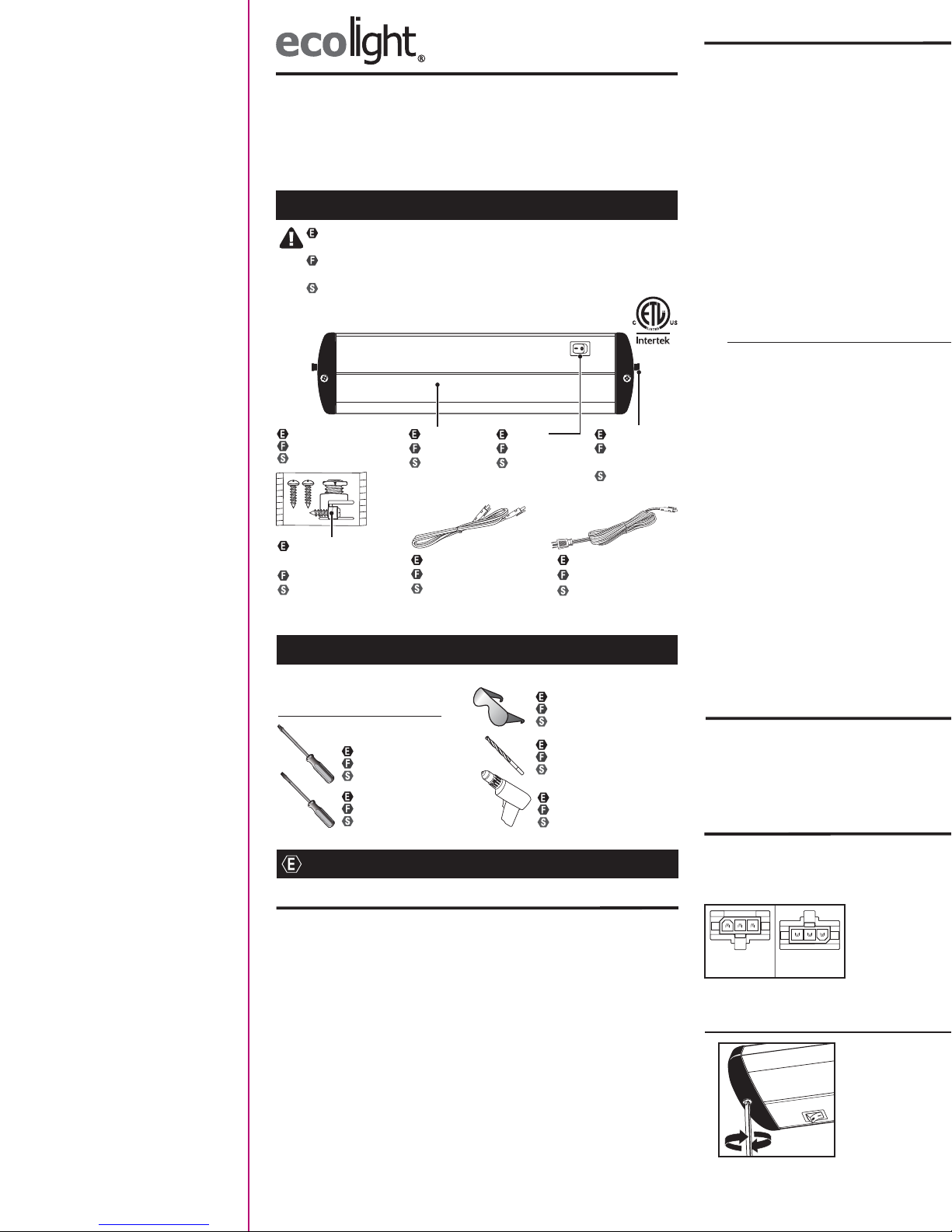
Verify the following contents:
AVERTISSEMENT : Veuillez lire ce mode d'emploi du début à la fin avant
de commencer l'installation. Vérifiez le contenu suivant :
ADVERTENCIA: Por favor, lea este manual completo antes de realizar la
instalación. Verifique el siguiente contenido:
*Actual hardware may differ from illustration. / La quincaillerie incluse peut être différente de l’illustration. / Los aditamentos reales pueden diferir
de los que se muestran en la ilustración.
Hardware kit*
Trousse de quincaillerie*
Kit de aditamentos*
NM cable
strain relief
connector
Cordon de raccordement
Cable de enlace
Required/Nécessaire/Se necesita
Safety glasses
Lunettes de sécurité
Gafas de seguridad
Flathead screwdriver
Tournevis à tête plate
Destornillador de cabeza plana
Phillips screwdriver
Tournevis cruciforme
Destornillador Phillips
Installation time: 30 minutes
Temps d’installation : 30 minutes
Tiempo de instalación: 30 minutos
Drill bits 1/16 in.
Forets de 1/16 po
Brocas para taladro de 1/16 pulg
Drill
Perceuse
Taladro
Linking cord
Cordon de raccordement
Cable de conexión
Power cord
Cordon d’alimentation
Cable de alimentación
Diffuser
Diffuseur
Difusor
Switch
Interrupteur
Interruptor
Locking tab
Languette de
verrouillage
Lengüeta de
empalme
English
Warnings and Cautions
Important Safety Instructions
This unit has a grounded plug as a safety feature. This plug will only fit in an
outlet one way. If it does not fit, do not use the outlet or contact a qualified
electrician. Never use with a power strip unless the plug can be completely
inserted. Do NOT attempt to defeat this feature.
WARNING: To reduce the risk of FIRE, ELECTRIC SHOCK, OR INJURY TO
PERSONS:
1. For INDOOR USE ONLY.
2. Not intended for installation in plastic cabinets.
3. The mounting surface should be flat and sturdy enough to support the
fixture.
4. Do NOT mount the fixture to cabinets having a material thickness less
than 1/4 in.
5. Not intended for recessed installation in ceilings or soffits.
6. Do NOT use in wet locations.
7. Do NOT use for illumination of aquariums.
8. Do NOT mount over sinks or stoves.
9. Do NOT touch, operate, or install fixture while in contact with water.
10. Do not remove the protective LED lens or touch the LEDs at any time.
11. Use a soft cloth to clean the diffuser and/or fixture.
PLUG-IN/LINKING SAFETY INFORMATION:
12. Do NOT attempt to install while plugged in.
13. Use only insulated staples or plastic ties to secure the power or linking
cords.
14. The National Electrical Code (NEC) does not permit cords to be
concealed where damage to insulation may go unnoticed. To prevent
fire danger, do not run cord behind walls, ceilings, soffits, cabinets, or
similar permanent structures where it may be inaccessible for
examination. Cords should be visually examined periodically and
immediately replaced when any damage is noted.
15. Do not use an extension cord. Use power strip with integral overcur-
rent protection to supply power to the fixture.
16. The total wattage of ALL the fixtures linked together in one chain
should NOT exceed 360 watts. Exceeding the total wattage will result in
a hazardous situation. Fixture wattage can be found on back of fixture.
IMPORTANT: These LED light heads use light emitting diodes to provide
light. LEDs are electronic semiconductors and do not have a filament that
can burn out like an ordinary light bulb. As such, the LED light heads can
last up to 50,000 hours when used intermittently, and therefore, never need
replacing.
SAVE THESE INSTRUCTIONS IN A LOCATION CLOSE TO THE LIGHT
FIXTURE TO REFER TO THEM AT A LATER TIME. Before installation, plug in
fixture to a 120 V, 60 Hz electrical outlet to check for proper operation. Then,
unplug and begin the installation.
Dimmer Instructions
THIS FIXTURE IS DIMMABLE BY SPECIFIC FORWARD PHASE ELECTRONIC (TRAIC)
DIMMERS. Dimmers tested to be compatible with this fixture are the Lutron: Diva®
C*L™: DVWCL-153P* or DVCL-153P*, Lumea® C*L™: LGCL-153P*, and Toggler® C*L
™: TGCL-153P*. Not recommended for use with motion or light sensors, timers, or
any other external controls.
Mounting Instructions
There are two methods to mount the fixture to a cabinet. The first is the EASY
MOUNTING INSTALLATION method that uses the pre-installed screws located at
both ends of the fixture. The other is the TRADITIONAL MOUNTING INSTALLATION
method, which utilizes the keyhole slots located on the backside of the fixture.
The fixture can be mounted without utilizing pilot holes.
Firmly hold the fixture against the mounting surface and
begin turning the mounting screws until they are fully
driven in and the fixture is firmly attached to the
mounting surface (Fig. 1). NOTE: DO NOT overtighten
the screws, as it may result in damage to the fixture or
the mounting surface. Direct Wire Installation Only:
Determine the fixture location, but do not mount until the
wiring steps are completed.
Fig. 1
1
1
EASY MOUNTING INSTALLATION
DIRECT WIRE INSTALLATION
2
3
4
5
1
Disconnect power to the electrical box and remove the old fixture. If more than two
wire leads are present, keep track of which wires were connected together.
WARNING: DISCARD THE POWER CORD to avoid a dangerous situation.
Locate the fixture position and drill pilot holes at this time for Direct Wire
installation.
Fig. 14
Fig. 17
Before mounting, find a suitable location to mount the
fixture that will reach the power supply (within 5 feet)
or to reach adjoining fixture (within 18 inches).
The
fixture has two power ports located at each end of the
fixture. The “Power-In” port is located on the end next
to the on/off switch and is used to connect the fixture
to a power supply. The “Power-Out” port is located at the opposite end and is used to
link power to additional fixtures connected together.
TRADITIONAL MOUNTING INSTALLATION
the fixture is secure.
installation until the wiring steps are completed.
2
Fig. 2
2
1
Fig. 5
ONLY fit into this power port. When fully inserted, the catch on the top of the
connector plug will click into the power port. SECOND: Plug in the power cord into
an outlet and the installation is complete.
PLUG-IN INSTALLATION
Locate the mounting keyhole slots on the back of the fixture. Measure the
center-to-center distance to determine the distance the wood screws need to be
installed. Measure and mark the corresponding placement on the mounting
surface. NOTE: The wire compartment cover can be opened on the fixture and
trace the perimeter of keyhole slots.
bundled with the supply wires. Insert the end of that ground wire into the open hole
in the push-in connector
properly grounded, or the flexible whip or NM cable is connected to an electrical
box that is plastic and has no ground wire, or are unfamiliar with the methods of
properly grounding the fixture, consult a qualified electrician.
Fig. 11
Power-Out
Port
Power-In
Port
WARNING
• Shut off power at the circuit breaker or fuse panel before removing the
old fixture or installing the new one.
• LEDs can be damaged by electrostatic discharge (ESD) shock. Before
installation, discharge yourself by touching a grounded bare metal
surface to remove this hazard. To avoid damage, do not remove the
clear lens over the LED module.
CAUTION
• This device complies with Part 15 of the FCC rules. Operation is subject
to the following two conditions: (1) This device may not cause harmful
interference, and (2) this device must accept any interference received,
including interference that may cause undesired operation.
 Loading...