

ecolight SE1039-TBZ-02LF0-E User Manual
Model/Modèle/Modelo #:
SE1039-TBZ-02LF0-E
MOTION ACTIVATED LED SECURITY LIGHT (Page 1)
ÉCLAIRAGE DE SÉCURITÉ ACTIVÉ PAR
LES MOUVEMENTS
(Page 6)
LUZ LED DE SEGURIDAD ACTIVADA
POR MOVIMIENTO
(Página 11)
To Begin/Pour commencer/Para comenzar
WARNING: Please read this entire manual before installation.
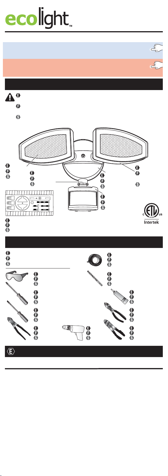
Verify the following contents:
AVERTISSEMENT : Veuillez lire ce mode d'emploi du début à la fin avant
de commencer l'installation. Vérifiez le contenu suivant :
ADVERTENCIA: Por favor, lea este manual completo antes de realizar la
instalación. Verifique el siguiente contenido:
Diffuser
Diffuseur
Difusor
Hardware kit (Actual hardware may differ from illustration).
Trousse de quincaillerie (La quincaillerie incluse peut être différente de l’illustration.)
Kit de aditamentos (Los aditamentos reales pueden diferir de los que se muestran en la ilustración.)
Sensor arm
Bras du détecteur
Brazo del sensor
GND
FRONT
Wall plate
Plaque murale
Pared plana
Sensor head
Tête du détecteur
Cabezal del sensor
Light head
Tête de
lampe
Cabeza
de luz
Required/Nécessaire/Se necesita
Installation time: 45 minutes
Temps d’installation : 45 minutes
Tiempo de instalación: 45 minutos
Safety glasses
Lunettes de sécurité
Gafas de seguridad
Phillips screwdriver
Tournevis cruciforme
Destornillador Phillips
Flathead screwdriver
Tournevis à tête plate
Destornillador de cabeza plana
Wire cutters
Coupe-fil
Pinzas cortacables
Drill
Perceuse
Taladro
Electrical tape
Ruban isolant
Cinta aislante
Drill bits 1/16 in.
Forets de 1/16 po
Brocas para taladro de 1/16 pulg
Silicone
Silicone
Silicona
Pliers
Pinces
Pinzas
Wire strippers
Pinces à dénuder
Pinzas pelacables
English
Warnings and Cautions
WARNING
• Shut off power at the circuit breaker or fuse panel before removing the
old fixture or installing the new one.
• LEDs can be damaged by electrostatic discharge (ESD) shock. Before
installation, discharge yourself by touching a grounded bare metal
surface to remove this hazard. To avoid damage, do not remove the
clear lens over the LED module.
CAUTION
• DO NOT USE THIS FIXTURE WITH A DIMMING CIRCUIT. If dimmer
controls are present, remove them and replace them with regular
electrical switches. If a three-way dimmer is present, replace it with a
regular three-way switch. If unfamiliar with electrical installations, it is
recommended a qualified electrician do the installation.
• This device complies with Part 15 of the FCC rules. Operation is subject
to the following two conditions: (1) This device may not cause harmful
interference, and (2) this device must accept any interference received,
including interference that may cause undesired operation.
- 1 -
GND
FRONT
Important Safety Instructions
GND
FRONT
GND
FRONT
GND
FRONT
45°
WARNING: To reduce the risk of FIRE, ELECTRIC SHOCK, OR INJURY TO
PERSONS:
1. Do NOT touch LEDs.
2. Do NOT remove the protective clear LED lens.
3. Do NOT look directly at lighted LEDs for any length of time.
4. Do NOT touch, operate, or install fixture while in contact with water.
5. Electrical requirements: 120 V AC, 60 Hz., 0.31A. Minimum 90° supply
conductors.
6. Do not leave bare wires exposed outside the wall canopy enclosure.
7. Suitable for installation onto round surface mount electrical boxes or
recessed electrical boxes rated for wet locations. Fixture can be wall or
eave mounted. NOT suitable for ground mount installations.
8. Do NOT allow the sensor head to touch the LED head housing. Maintain
at least 1 in. spacing between the LED heads and the sensor head.
9. For proper operation and protection against water damage, the motion
sensor head controls MUST be facing downward.
10. Do NOT mount below 5 ft.
SAVE THESE INSTRUCTIONS IN A LOCATION CLOSE TO THE FIXTURE TO
REFER TO THEM AT A LATER TIME.
Select the installation location carefully. Do not install in areas having
pedestrian or motorized traffic, pools or bodies of water, or trees/bushes
that move in the wind. All of these may trigger the motion sensor security
light and may be disruptive to the intended operation of the light. Do NOT
install near other sources of light, as this can fool the Dusk-to-Dawn sensor
into thinking it is daylight.
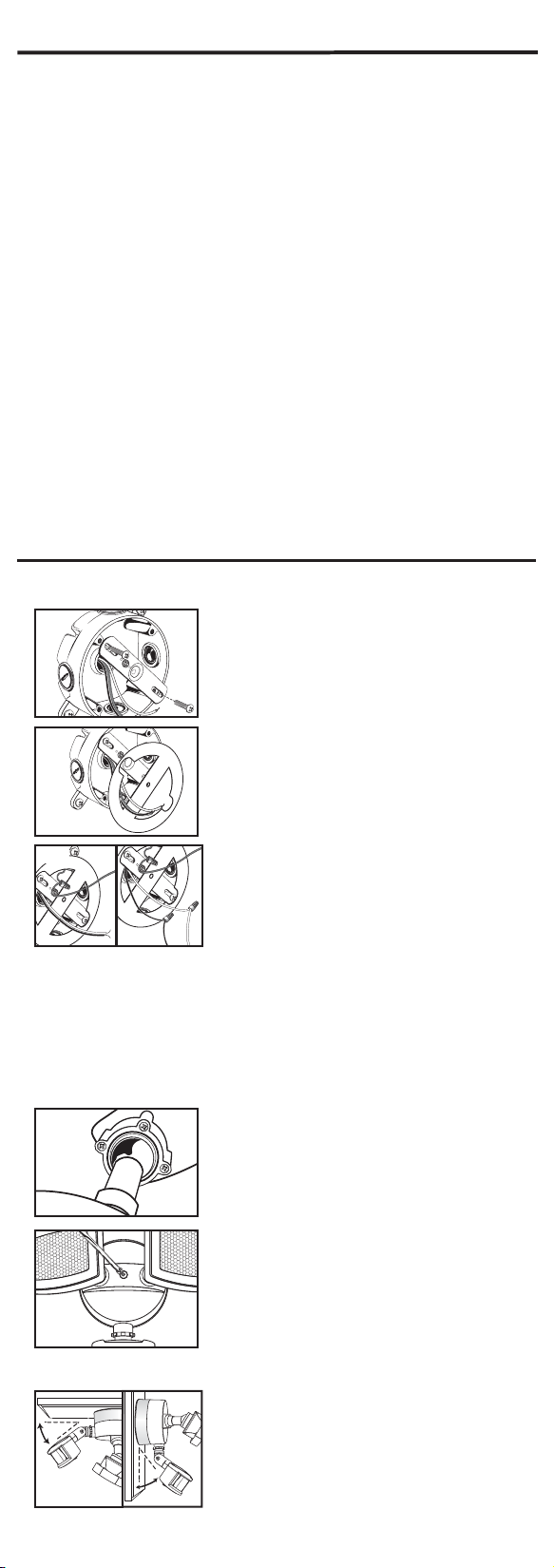
Installation For Round Surface Mount Electrical Boxes
Disconnect power to the electrical box and remove the old fixture. If more than two
wire leads are present, keep track of which wires were connected together.
1
Fig. 1
Pull the supply wires out of the electrical box. Using the
machine screws that fit the electrical box, secure the
mounting strap to the electrical box, making sure that
the side marked “FRONT” is facing out (Fig. 1).
2
Fig. 2
Remove the protective paper barrier from the adhesive
face of the foam gasket. Trace the supply wires through
the openings in the gasket and adhere the gasket to the
mounting strap and outer edge of the round surface
mount electrical box (Fig. 2).
Fig. 3
3
For safety and proper installation, the fixture must be
properly grounded. If unfamiliar with the methods of
properly grounding the fixture, consult with a qualified
electrician. A green copper ground wire is
Fig. 4
pre-attached to the fixture. If the electrical box is made
of plastic and/or has a green or bare copper grounding
wire inside, the fixture grounding wire and the electrical box ground wire should be
connected together using one of the wire nuts included
(Fig. 3)
. If the electrical box is
made of metal and already grounded, secure the bare end of the fixture ground wire
to the mounting strap marked “GND” using the green grounding screw. Connect the
supply leads from the electrical box to the fixture wire leads using the wire nuts. The
black lead from the fixture is connected to the black supply lead and the white fixture
lead is connected to the white supply lead
(Fig. 4)
. Tighten the wire nuts properly to
prevent them from coming loose. If needed, use electrical tape to secure the wire
nuts onto the wire leads. Push the excess wires back into the electrical box.
4
Fig. 5
If the light head is loose and will not hold its position
tighten the screws located on the backside of the light
head that surround the pivot joint (Fig. 5). NOTE: Tighten
the screws before securing the fixture to the electrical
box.
5
Position the wall plate over the mounting strap so the
center hole of the wall plate aligns with the center hole
in the mounting strap. While holding the wall plate in
place, put the long machine screw through the center
hole of the wall plate and mounting strap. Tighten the
Fig. 6
screw properly to secure the wall plate onto the
electrical box (Fig. 6). NOTE: Make sure the gasket
properly seals the gap between the wall plate and the electrical box to prevent water
seepage into the electrical box.
6
45°
If eave mounting the fixture, position the sensor head
with the adjustment controls and drain holes facing
downward to prevent water damage (Fig. 7). The
position of the sensor head should not exceed 45
degrees from horizontal.
- 2 -
Fig. 7
GND
FRONT
FRONT
GND
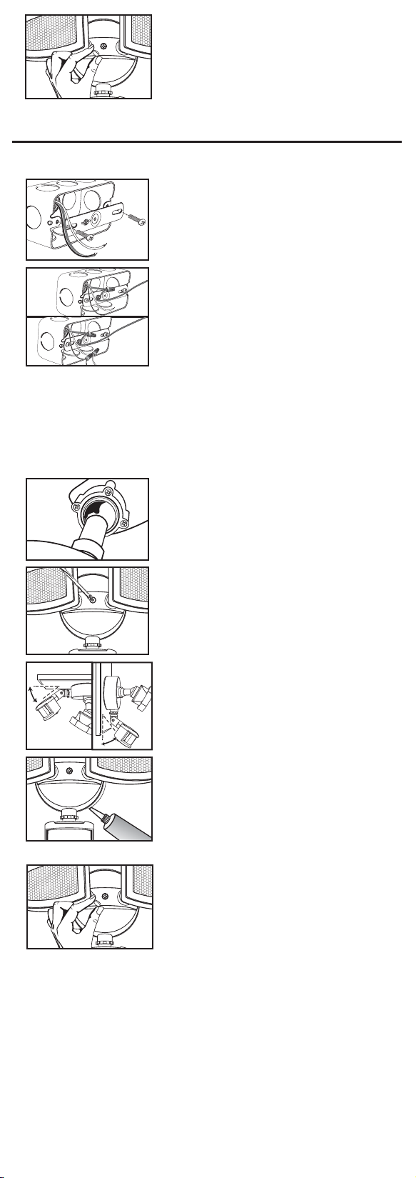
7
Restore power to the electrical box at the circuit
breaker or fuse panel. Make sure the wall switch that
controls the electrical box for your security light is
returned to the “ON”position and check that your light is
functioning properly. If the light is functioning properly,
Fig. 8
fit the silicone cap into the mounting screw opening to
prevent water seepage into the housing (Fig. 8).
Installation For Recessed Electrical Boxes
Disconnect power to the electrical box and remove the old fixture. If more than two
wire leads are present, keep track of which wires were connected together.
1
Pull the supply wires out of the electrical box. Using the
machine screws that fit the electrical box, secure the
mounting strap to the electrical box, making sure that
the side marked “FRONT” is facing out (Fig. 1).
Fig. 1
2
Fig. 2
For safety and proper installation, the fixture must
be properly grounded. If unfamiliar with the methods of
properly grounding the fixture, consult with a qualified
electrician. A green copper ground wire is pre-attached
to the fixture. If the electrical box is made of plastic and/
or has a green or bare copper grounding wire inside, the
fixture grounding wire and the electrical box ground
Fig. 3
wire should be connected together using one of the
small wire nuts included (Fig. 2). If the electrical box is made of metal and already
grounded, secure the bare end of the fixture ground wire to the mounting strap marked
“GND” using the green grounding screw. Connect the supply leads from the electrical
box to the fixture wire leads using the wire nuts. The black lead from the fixture is
connected to the black supply lead and the white fixture lead is connected to the white
supply lead (Fig. 3). Tighten the wire nuts properly to prevent them from coming loose.
If needed, use electrical tape to secure the wire nuts onto the wire leads. Push the
excess wires back into the electrical box.
3
Fig. 4
If the light head is loose and will not hold its position
tighten the screws located on the backside of the light
head that surround the pivot joint (Fig. 4). NOTE: Tighten
the screws before securing the fixture to the electrical
box.
4
Position the wall plate over the mounting strap so
the center hole of the wall plate aligns with the center
hole in the mounting strap. While holding the wall plate
place the long machine screw through the center
hole of the wall plate and mounting strap. Tighten
Fig. 5
5
45°
the screw properly to secure the wall plate onto the
mounting surface (Fig. 5).
If eave mounting the fixture, position the sensor head
with the adjustment controls and drain holes facing
downward to prevent water damage (Fig. 6). The
position of the sensor head should not exceed 45
degrees from horizontal.
Fig. 6
6
45°
Restore power to the electrical box at the circuit
breaker or fuse panel. Make sure the wall switch that
controls the electrical box for your security light is
returned to the “ON” position and check that your light
Fig. 7
is functioning properly. If the light is functioning
properly, use silicone adhesive caulking (not included)
to caulk the gap between the wall plate and the
mounting surface to prevent water seepage into the electrical enclosure (Fig. 7).
7
Fit the silicone cap into the mounting screw
opening to prevent water seepage into the
housing (Fig. 8).
Fig. 8
- 3 -
- 3 -

Operating Instructions
The motion sensor on this fixture has a built in
Dusk-to-Dawn
motion sensor will not activate during daylight hours regardless of motion detection.
1
motion or not, and regardless of whether it is day or night.] Leave the rotary knob in
the “TEST” area and test the sensitivity by crossing in the path of the sensor. The light
will come on only if it senses movement. Once movement stops, it will turn off in 5
seconds (Fig. 1). The test is now complete.
2
Fig. 2
is achieved (Fig. 2). NOTE: The higher sensitivity level increases the likelihood of a false
activation being triggered. For maximum range performance, allow the fixture to operate
in any setting (with power) for at least 48 hours.
3
Fig. 3
sensor at a body of water, bushes or plants that may move in the wind, pedestrian
traffic, moving cars, etc., as this will trigger the motion sensor. NOTE: If the sensor
arm becomes loose, it will not hold the sensor head at the proper angle. Readjust the
sensor head and tighten the joint screw on the sensor arm.
4
light down to 10 seconds once motion is detected. It may be necessary to adjust the
“TIMER” knob several times until the desired length of time is determined (Fig. 5).
sensor disables the motion sensor during daylight hours. The
The motion sensor must be tested before setting the
time and sensitivity levels. The TEST option is located
on the TIMER control knob on the underside of the
sensor head. To test the fixture, switch the wall switch
that controls power to the fixture to the ON position and
turn the rotary knob to the “TEST” area. [The lights will
Fig. 1
come on for 40 seconds regardless of whether there is
The control knob located on the opposite side is marked
SENSITIVITY, which determines the degree of motion
detection. Rotating this knob clockwise raises the
sensitivity of the motion sensor for up to 60 ft. of distance.
Rotating the knob counterclockwise lowers the sensitivity
down to as close as 5 ft. It may be necessary to adjust the
“SENSITIVITY” knob several times until the proper setting
The 180 degree coverage of the motion sensor is
measured side to side (Fig. 3). Therefore, the sensor will
better detect motion across the field of view
(side-to-side), rather than motion coming straight at the
45°
sensor (in-and-out). Adjust the motion sensor head so
that it detects motion moving across the coverage area.
Fig. 4
The position of the sensor head should not exceed 45
degrees from horizontal (Fig. 4). Do not aim the motion
Once the fixture has been tested for proper operation
and sensitivity, rotate the rotary knob on the TIMER
control to the “TIMER” area. The “TIMER” position
allows the fixture to go into AUTO motion sensor mode.
Rotating the knob clockwise increases the duration of
light up to 5 minutes once motion is detected. Rotating
Fig. 5
the knob counterclockwise decreases the duration of
Dusk-to-Dawn
sensor. The
5
To control the security light from inside the home, activate manual “ON” mode by
toggling the wall light switch OFF and ON within 2 seconds. The security light will turn
on and stay on for approximately 8 hours, or until the dusk-to-dawn sensor detects light
in the morning. Once the dusk-to-dawn sensor detects light, the manual “ON” mode
will automatically go back to its original settings of the AUTO motion sensor mode.
Security Light Operation
MODE TIMER KNOB WALL SWITCH SENSITIVITY KNOB
Test mode. Test area. On. Any setting.
AUTO motion sensor mode. Timer area. On. Any setting.
Manual “ON” mode. Timer area. Toggle OFF and ON Any setting.
within two seconds.
Return to AUTO motion Timer area. On. Any setting.
sensor mode
Care and Maintenance
IMPORTANT: This light fixture uses light emitting diodes (LEDs) to provide
light. LEDs do not have a filament to burn out like a traditional light bulb.
LEDs gradually emit less light over their lifetime, but will typically last 36,000
hours in a residential environment.
Periodically clean the fixture and diffuser using a mild, non-abrasive cleaner
and soft cloth. When cleaning the fixture, make sure the power is turned off.
Do not spray cleaner directly onto any part of the fixture or LEDs.
- 4 -- 4 -

Replacement Parts List
Keep this guide handy for
ordering replacement parts.
Hardware Kit
ZH-SE1039F02-TBZ
Troubleshooting Guide
Extreme hot or cold weather could affect the performance of the built-in sensors that detect
body heat. Certain winter clothing can shield a person’s body heat from the sensor during
extreme cold weather. During extreme hot weather, the sensor may not be able to distinguish
the difference between normal body temperatures and the surrounding high temperatures.
The sensor will begin working normally once weather conditions return to normal.
Problem Cause Solution
Light does not come on 1. No power is being 1. Check that circuit breaker and/or
at night when motion delivered to the fixture. wall switch power is on.
is detected.
2. Another light source is 2. Turn off surrounding lights and/or
causing the security light re-aim the sensor head.
to think it is daylight.
3. Wiring inside electrical 3. AFTER turning power off to the
came loose. fixture, reconnect any loose wiring.
Security light comes on 1. Dusk-to-dawn sensor is in 1. Shine a flashlight onto the light
on during the day. a shaded area and it fooled sensor. If the security light turns off
into thinking it is nighttime. then the fixture is mounted in an
area that does not allow enough
light to enter the sensor. Relocate
the security light.
1. Dusk-to-dawn sensor 2. If under warranty, contact
is faulty. Customer Service.
Security light cycles ON 1. Dusk-to-dawn sensor is 1. Change the position of the light head,
and OFF continuously. sensing reflected light aim light away from the reflecting
from the security light. surfaces.
2. Put a small piece of black electrical
tape over the Dusk-to-dawn sensor.
3. Relocated the security light to a
different location where it no longer
causes reflected light.
Security light comes on for 2. Light is sensing motion in 1. Make sure the sensor is not picking
on for no apparent reason the detection zone. moving objects such as bushes,
at night. trees, traffic, water, etc.
2. Test the motion sensor by covering
up the front curved lens with a
cardboard to block the view. If the
light turns off then something in the
detection zone is triggering the
sensor. Reposition the motion sensor
or change the sensitivity (distance)
of the sensor.
Need Help?
In the event you are missing a part or have questions regarding installation
please visit our website at www.goodearthlighting.com/support or
call the Customer Care Center 1-800-291-8838,
8:30 a.m.-5 p.m., CST, Monday-Friday.
Ecolight™ Warranty
6 YEAR LIMITED WARRANTY
The manufacturer warrants this lighting fixture to be free from defects in materials and
workmanship for a period of (6) years from the date of original purchase by the
consumer. The fixture is not warrantied for use in a commercial or retail application.
The warranty is limited to use in a residential environment. We will repair or replace (at
our option) the unit in the original color and style if available, or in a similar color and
style if the original item has been discontinued, without charge. Defective units must be
properly packed and returned to the manufacturer with a letter of explanation and your
original purchase receipt showing date of purchase. Call 1-800-291-8838 to obtain a
return authorization number and an address where to ship your defective product.
Note: C.O.D. shipments will NOT be accepted. The liability of the manufacturer is in any
case limited to replacement of the defective light fixture product. The manufacturer will
not be liable for any other loss, damage, labor costs or injury which is caused by the
product. This limitation upon the liability of the manufacturer includes any loss,
damage, labor costs or injury which is (I) to person or property or otherwise; (II)
incidental or consequential in nature; (III) based upon theories of warranty, contract,
negligence, strict liability, tort, or otherwise; or (IV) directly, or indirectly related to the
sale, use, or repair of the product. This warranty gives you specific rights, and you may
also have other rights which vary from state to state.
Ecolight™ 5260 Capitol Drive, Wheeling, IL 60090 Printed in China
- 5 -- 5 -
 Loading...