

Ecolab Chameleon PLUS BW3, Chameleon PLUS BW4, Chameleon PLUS BW7, Chameleon PLUS BF4, Chameleon PLUS BF3 Installation Manual
...Page 1
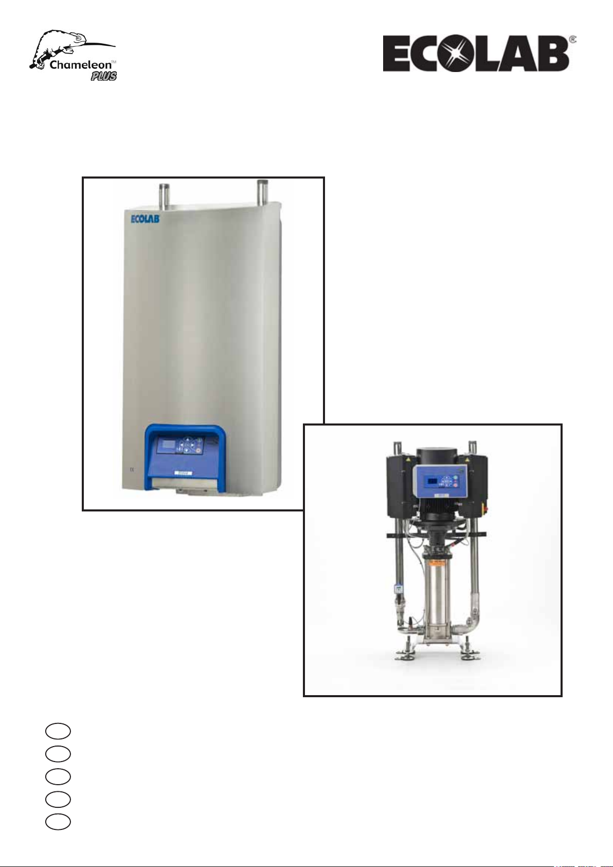
Booster Advanced / professional
EN
Installation Guide ........................................................2-3
DE
Installationsanleitung .................................................4-5
FR
Manuel d’installation ...................................................6-7
ES
Guía de la instalación .................................................8-9
DA
Installationsvejledning ...........................................10-11
Page 2
1. General information EN
5. Power supply
For safety reasons it is important to read all of the enclosed information
(Installation guide, Service manual, Spare parts, Operating instructions)
before mounting this equipment.. In addition, the legislation in force at the
time of purchase must always be considered in connection with the installation and mounting of this equipment, no matter the contents of this manual.
If there are matters of dispute please contact your dealer.
This equipment is produced and tested by specially qualied personnel,
following approved instructions to ensure our high level of product qual-
ity. After the product is nished and tested it is manually inspected with the
ultimate test carried out just before the product is released for shipping. To
obtain our high level of quality and long life we use stainless steel parts.
These parts, in deance of our manual inspections may still have some
sharp edges, which can present a cut hazard. Therefore it is advised always
to use protective gloves and show caution when installing the equipment.
2. Preparation Wall / Floor
If the wall is made of bricks or concrete, the enclosed screws and rawl plugs are
usable, otherwise you have to make sure that the carrying
capacity of the wall is sufcient.
Note: The pipeline must be rinsed through before the system is
connected. See service manual.
Note: Remove cover before the system is mounted on the wall.
Note: The weight of the unit are listed in the Service manual under the
section "Specications"
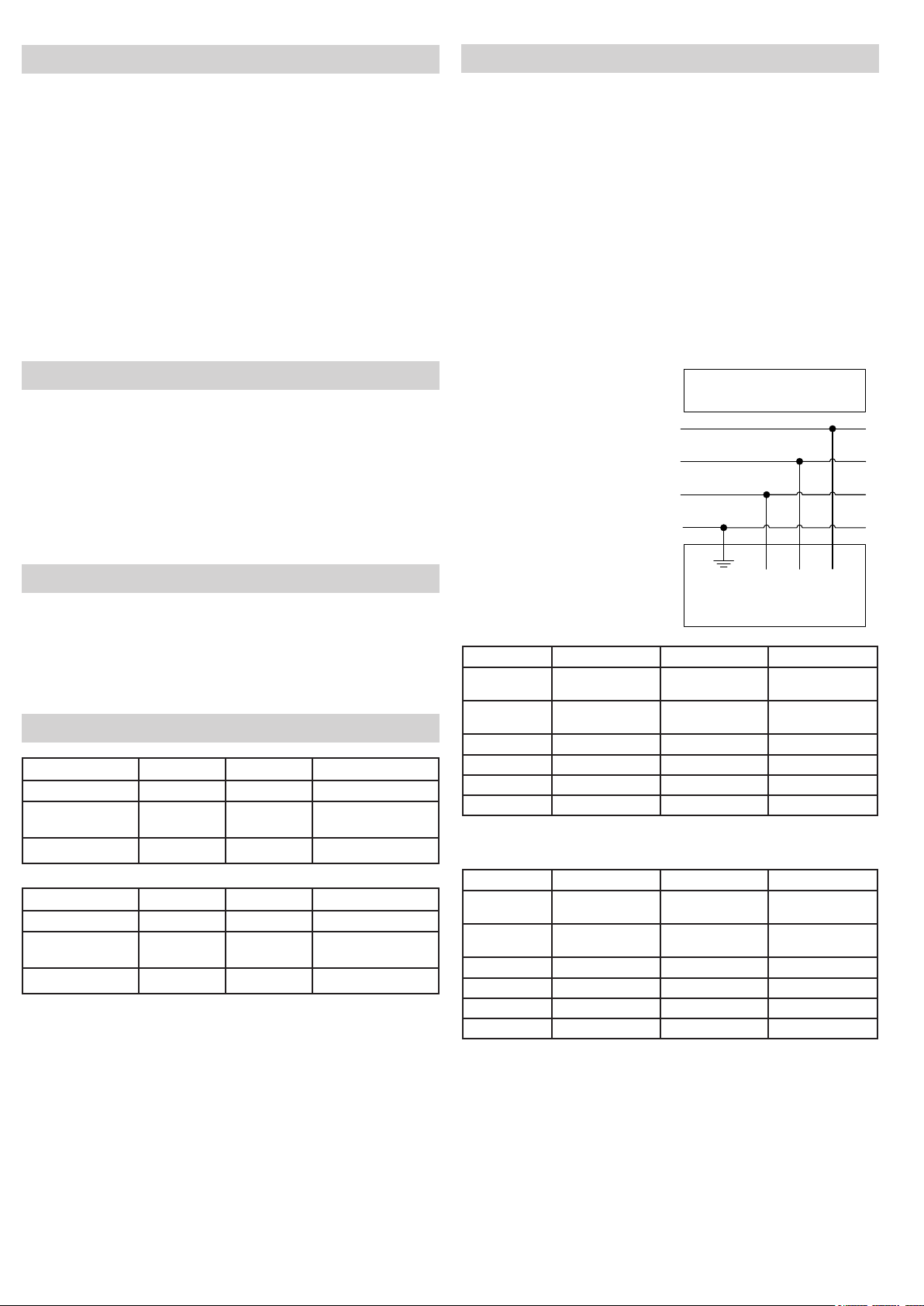
Connection instruction is mounted on the cables.
The phase order is subordinated.
Earth Leakage Circuit Breaker (ELCB).
When using an earth leakage circuit breaker (ELCB) also known as a residual
current device (RCD) or a residual current circuit breaker (RCCB) in a system
that incorporates a variable speed drive connected to 3 phase 400 V.
The trip level of the ELCB has to be 300 mA.
(30 mA used in house hold will malfunction due to earth leakage)
Service Switch:
The unit must always be connected to the main supply through a separate
service switch.
NB! Installation must always be in accordence with local legistration.
Mains
3/PE 400 Vac ± 10%
48 Hz ... 62 Hz
L1
L2
L3
PE
3. Placing/application
• Do not use the machine outdoors.
• Main station must be placed in frost free rooms only.
• Free space around the main station: min 1500 mm.
• Max. ambient temp. 40°C.
• Non vibrating surface.
4. Water supply
BW3 BW4 BW7
Water volume 100 l/min. 135 l/min 265 l/min
Pressure 0,2 - 0,8 MPa
(2 - 8 bar)
Max. temperature 70
o
BF3 BF4 BF8
Water volume 100 l/min. 135 l/min 265 l/min
Pressure 0,2 - 0,8 MPa
(2 - 8 bar)
Max. temperature 70
The supply line must be sized so that it can supply the minimum indicated pressure and water volume when connected to this equipment. When dimensioning
the water supply, it is recommended to increase the available volume with 15-20
% compared to the minimum requirements listed in the table.
o
0,2 - 0,8 MPa
(2 - 8 bar)
0,2 - 0,8 MPa
(2 - 8 bar)
C 70oC 70oC
0,2 - 0,8 MPa
(2 - 8 bar)
0,2 - 0,8 MPa
(2 - 8 bar)
C 70oC 70oC
Green/Yellow L3 L2 L1
Note: Phase sequence unimportant.
Connecting cable.
BW3 BW4 BW7
Voltage: 3/PE 400 Vac
quenz:
Fre
Motor load: 4 kW 5.5 kW 10 kW
Nominal current: 10.6 A 14.2 A 27 A
Fuse: 16 A 20 A 35 A
L1, L2, L3, PE 2.5 mm
±10%
50/60 Hz
48 -0%…62 +0%
2
3/PE 400 Vac
±10%
50/60 Hz
48 -0%…62 +0%
2
2.5 mm
3/PE 400 Vac
±10%
50/60 Hz
48 -0%…62 +0%
6 mm
BF3 BF4 BF8
Voltage: 3/PE 400 Vac
quenz:
Fre
Motor load: 4 kW 5.5 kW 11 kW
Nominal current: 10.6 A 14.2 A 27 A
Fuse: 16 A 20 A 35 A
L1, L2, L3, PE 2.5 mm
±10%
50/60 Hz
48 -0%…62 +0%
2
3/PE 400 Vac
±10%
50/60 Hz
48 -0%…62 +0%
2
2.5 mm
3/PE 400 Vac
±10%
50/60 Hz
48 -0%…62 +0%
6 mm
2
2
Note: It is recommended to mount a mixing system on the water
connection immediately before the outlet which is used.
Recomented water hardness 14-18 dH°. The equipment will
operate with water hardness exciding this level however, de
scaling of pump system, injectors and like must be
expected depending on use pattern and water quality.
Furthermore, wear of the mechanical parts will increase as well.
If not supplied, lter should be mounted.
2
Page 3

6. Piping
The pipe system should be made of stainless steel pipes. The pipe joints
should be made in a way that makes separation possible in case of e.g.
repairs, movement or similar.
All thread according to ISO 228
The dimensions stated below are only intended as a guide.
Calculations on a new pipe installation should always be based on pressure
loss tables for pipes and ttings.
Pipe connections
Recommended pipe dimensions 5/4" RG 5/4" RG 2" RG*
Pipe dimensions unit 5/4" RG 5/4" RG 5/4" RG
BW3 BW4 BW7
Pipe connections
Recommended pipe dimensions 5/4" RG 5/4" RG 2" RG*
Pipe dimensions unit 5/4" RG 5/4" RG 5/4" RG
* To ensure an always sufcient water ow and a minimum pressure loss,
we recommend using a 2" pipe connection.
Always take into consideration, when planning and carrying out a new
installation, that the pipe connection of the unit is 5/4".
Note: A 5/4” - 2" closing valve should be mounted on the water supply immediately before the Booster and dirt lter if any.
BF3 BF4 BF8
7. Assembly
Dimensions see g.1 - g.9
Professional:
Dimensions see g. 1
It is recommended to mount the main station at an appropriate height (ap-
prox. 1 m above the oor) on a brick or concrete wall, according to mounting instructions in g. 2.
Mount the wall bracket.
For brick or concrete wall please use the screws and rawlplugs enclosed.
Now hang the main station on the wall bracket.
Secure the main station to the wall bracket using the enclosed screws.
Advanced:
It is recommended to mount the main station at an appropriate height (ap-
prox. 1 m above the oor from the bottom of the wall bracket) on a brick or
concrete wall, according to mounting instructions in g. 4.
Mount the wall bracket.
Mount the main station with suitable securing. For brick or concrete wall
please use the screws and rawlplugs enclosed. To make mounting easier
we recommend marking the wall according to g. 4. The main station must
be lifted until the auxiliary point on the right side is in line with the marking
on the wall. Now hang the main station on the wall bracket.
Fasten or tighten the main station to the wall bracket using the enclosed
screws.
3
Page 4
1. Generelle Informationen DE
Um eine optimale Sicherheit zu gewähren, ist es sehr wichtig, dass sämtli-
che beiliegende Informationen (Installationsanleitung, Service-Handbuch,
Ersatzteil, Bedienungsanleitung) studiert und durchgelesen worden sind,
bevor zuletzt dann die Montage erfolgt. Ebenfalls müssen die zu jeder Zeit
geltenden Gesetze in Verbindung mit Installation und Montage befolgt und
eingehalten werden – ungeachtet des Inhalts dieses Service-Handbuches.
In Zweifelsfragen kontaktieren Sie bitte immer den Händler (Lieferanten).
Diese Anlage wurde, gemäß zugelassenen Instruktionen, von profes-
sionellem Personal produziert und getestet, um dem Produkt unser hohes
Qualitätsniveau zu sichern. Nachdem das Produkt fertig produziert und
teils getestet worden ist, werden eine manuelle Inspektion und ein ab-
schließender Test vorgenommen, bevor das Produkt dann zur endgültigen
Lieferung freigegeben wird.
Um unser hohes Qualitätsniveau und eine lange Produktlebensdauer zu
sichern, wird in weitem Ausmaß nur rostfreier Stahl zur Produktion verwendet. Diese Tatsache kann, trotz unserer weitgehenden Inspektion, in
seltenen Fällen das Produkt mit scharfen Kanten und Ecken versehen, die
das Risiko mit sich bringen Schnittwunden verursachen zu können. Daher
empehlt es sich immer Arbeitshandschuhe zu tragen und im Übrigen mit
Vorsicht die Anlage Hand zu haben.
2. Vorbereitung
Ist die Beschaffenheit der Wand Back-/Ziegelstein oder Beton, können die
beiliegenden Schrauben und Dübel verwendet werden; ansonsten muss
man sichern, dass die Tragfähigkeit ausreichend ist.
NB! Die Rohrleitung muss durchgespült werden, bevor die Anlage
angeschlos sen werden darf.
NB! Entfernen Sie das Cover, bevor die Anlage an der Wand montiert wird.
NB! Das Gewicht der Anlage nden Sie im Servicemanual unter "Spezika
tionen".
NB! Es empehlt sich ein Mischsystem an der Wasserzufuhr zu instal
lieren, das mit Vorteil unmittelbar vor dem Ausgang, der benutzt
wird, angebracht werden kann. Empfohlene Wasser härte 14.18
dH. Die Anlage funktioniert auch bei Installationen mit höherer
Wasserhärte. Es ist aber zu erwarten, dass Pumpen system,
Injektoren und andere Wasserberührte Funktionselementen,
abhängig von Gebrauchsmuster und Wasserqualität, entkalkt
werden müssen. Außerdem werden die mechanischen Teile mehr
abgenutzt.
Wenn nicht schon damit versorgt, bitte ein Filter montieren.
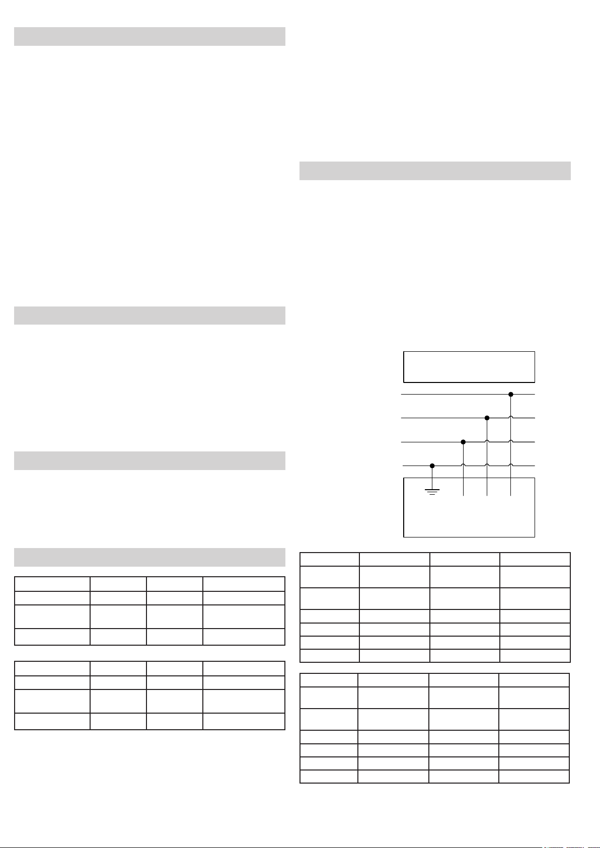
5. Stromanschluss
Eine Anschluss-Anleitung ist auch am Kabel montiert.
Die Phasen-Reihenfolge ist untergeordnet.
FI-Schutzschalter (ELCB):
Verwenden Sie einen universalstromsempndlichen Schalter, der gegen
alle Stromarten sowohl AC und gegen die Konstante DC empndlich ist.
In Anlagen die mit einem Frequenzumrichter mit dreiphasigem Netzanschluss (L1/L2/L3) ausgestattet sind, wird ein FI-Schutzschalter (ELBC)
vom Typ B angewandt, das gemäß EN/DS 50178 zugelassen ist.
Deshalb verwenden Sie einen FI-Schutzschalter vom Typ B, PFI 3 300 mA.
Immer einen separaten Serviceschalter vor der Anlage montieren.
Hinweis! Die Installation muss immer gemäß den örtlichen gesetzlichen
Bestimmungen erfolgen.
Mains
3/PE 400 Vac ± 10%
48 Hz ... 62 Hz
L1
L2
L3
3. Platzierung
• Das Gerät eignet sich nicht für den Einsatz im Freien.
• Die Hauptstation muss in einem frostsicheren Raum platziert werden.
• Freiraum um die Hauptstation herum: Min.1500 mm.
• Max. Umgebungstemperatur 40°C
• Nicht vibrierende Oberäche.
4. Wasserzufuhr
BW3 BW4 BW7
Wassermenge 100 l/min. 135 l/min 265 l/min
Druck 0,2 - 0,8 MPa
(2 - 8 bar)
Max. Temperatur 70
o
0,2 - 0,8 MPa
(2 - 8 bar)
0,2 - 0,8 MPa
(2 - 8 bar)
C 70oC 70oC
BF3 BF4 BF8
Wassermenge 100 l/min. 135 l/min 265 l/min
Druck 0,2 - 0,8 MPa
(2 - 8 bar)
Max. Temperatur 70
o
0,2 - 0,8 MPa
(2 - 8 bar)
0,2 - 0,8 MPa
(2 - 8 bar)
C 70oC 70oC
Die Zufuhrkette muss so dimensioniert werden, dass sie bei Anschluss an
unsere Anlage mindestens den oben angegebenen Druck und die gezeigte
Wassermenge erfüllen kann. Wir empfehlen Ihnen die Wasserversorgung
15-20% höher als den im Schema angegebenen min. Wert zu dimension-
ieren.
PE
Green/Yellow L3 L2 L1
Note: Phase sequence unimportant.
Connecting cable.
BW3 BW4 BW7
Spannung: 3/PE 400 Vac
Frequenz: 50/60 Hz
Motoreffekt: 4 kW 5.5 kW 10 kW
Nomineller Strom:
Sicherung: 16 A 20 A 35 A
L1, L2, L3, PE 2.5 mm
±10%
48 -0%…62 +0%
10.6 A 14.2 A 27 A
2
3/PE 400 Vac
±10%
50/60 Hz
48 -0%…62 +0%
2
2.5 mm
3/PE 400 Vac
±10%
50/60 Hz
48 -0%…62 +0%
6 mm
BF3 BF4 BF8
Spannung: 3/PE 400 Vac
Frequenz: 50/60 Hz
Motoreffekt: 4 kW 5.5 kW 11 kW
Nomineller Strom:
Sicherung: 16 A 20 A 35 A
L1, L2, L3, PE 2.5 mm
±10%
48 -0%…62 +0%
10.6 A 14.2 A 27 A
2
3/PE 400 Vac
±10%
50/60 Hz
48 -0%…62 +0%
2
2.5 mm
3/PE 400 Vac
±10%
50/60 Hz
48 -0%…62 +0%
6 mm
2
2
4
Page 5

6. Leitung der Rohre
Es empehlt sich ein Rohrsystem in rostfreiem Stahl anzuwenden. Die Rohrverbindungen sollten so gefertigt sein, dass ein evt. Separation möglich
ist, die im Falle einer Reparation, Verrückung u.dgl. von Vorteil wäre.
Alle Gewinde sind gemäss ISO 228.
Die untenstehenden Rohrdimensionen sind nur anleitend.
Wir empfehlen Ihnen Berechnungen einer Rohrinstallation immer auf Druckverlusttabellen über Rohr und Rohrttings zu gründen.
Rohranschlüsse
Empfohlene Rohrdimensionen 5/4" RG 5/4" RG 2" RG*
Rohrdimensionen Anlage 5/4" RG 5/4" RG 5/4" RG
Rohranschlüsse
Empfohlene Rohrdimensionen 5/4" RG 5/4" RG 2" RG*
Rohrdimensionen Anlage 5/4" RG 5/4" RG 5/4" RG
* Um einen zufriedenstellenden Wasserstrom und einen minimalen Druckverlust zu zicherstellen, empfehlen wir eine 2" Rohrverbindung.
Bei Planung und Ausführung eine neue Installation, immer mitnehmen, dass
der Rohranschluss der Anlage 5/4" ist.
Bemerken: Immer ein 5/4" Absperrventil auf der wasserzufuhr, bevor die
Booster-Anlage, montieren.
BW3 BW4 BW7
BF3 BF4 BF8
7. Aufstellen
Zielsetzung (siehe Fig.1 - Fig.9)
Professionel:
Es empehlt sich die Anlage in passender Höhe (etwa 1 Meter über dem
Boden) an einer Backstein– oder Betonwand zu montieren, wie in der
Montageanleitung Fig. 2 beschrieben.
Wandbeschlag montieren.
Für Backstein- oder Betonwand bitte beigelegten Schrauben und Dübeln
benutzen.
Jetzt die Hauptstation über den Beschlag senken.
Befestigen Sie die Hauptstation mit den beigelegten Schrauben und
Dübeln.
Advanced:
Es empehlt sich die Anlage in passender Höhe (etwa 1 Meter über dem
Boden) an einer Backstein– oder Betonwand zu montieren, wie in der Montageanleitung Fig. 4 beschrieben. Wandbeschlag montieren.Hauptstation
mit geeigneten Befestigungselementen montieren.
Für Backstein- oder Betonwand bitte beigelegten Schrauben und Dübeln
benutzen.
Um die Montage zu erleichtern, empehlt es sich, wie in der Montageanleitung/Fig. 4 beschrieben, Hilfsstriche auf der Wand zu markieren. Die Hauptstation so heben, dass der Hilfsstrich auf der rechten Seite des Kabinetts
mit dem Hilfsstrich auf der Wand uchtet. Jetzt die Hauptstation über den
Beschlag senken.
Befestigen Sie die Hauptstation mit den beigelegten Schrauben und
Dübeln.
5
Page 6

1. Généralités FR
Pour raison de sécurité, il est important de lire l’ensemble des informations.
(Guide d’installation, Manuel d’entretien, Pièces de rechange, Instructions
de fonctionnement), avant de monter cet équipement. De plus, la législa-
tion en vigueur au moment de l’achat doit toujours être prise en compte lors
de l’installation et du montage de cet équipement, quel que soit le contenu
de ce manuel. En cas litige, veuillez contacter votre distributeur.
Cet équipement est fabriqué et testé par du personnel spécialement
qualié, selon des instructions approuvées, an d’assurer un niveau de
qualité élevé du produit. Une fois le produit terminé et testé, il fait l’objet
d’un contrôle manuel. Un dernier test est effectué juste avant l’expédition
du produit. Pour assurer à nos produits un haut niveau de qualité et une
grande longévité, nous utilisons des pièces en acier inoxydable. Malgré
les contrôles manuels, ces pièces peuvent toutefois comporter des bords
tranchants et donc présenter un risque de coupure. Il est donc conseillé
de toujours porter des gants de protection et d’agir avec précaution lors de
l’installation de l’équipement.
2. Préparatifs
Si le mur est en briques ou en béton, les vis et chevilles fournies peuvent
être utilisées, sinon s’assurer que le mur est assez solide pour supporter
l’appareil.
Remarque - La canalisation doit être bien rincée avant de connecter
le système. Voir Manuel d’entretien.
Remarque - Retirer le couvercle avant de monter le système au mur.
Remarque - le poids de l’unité gure dans le manuel d’entretien, à la
section « Caractéristiques ».
3. Positionnement
• Ne pas utiliser l'appareil á l'extérieur.
• L’unité principale doit être placée uniquement dans un local à
l’abri du gel.
• Espace libre autour de l’unité principale : 1500 mm minimum.
• Temp ambiant maximal. 40°C.
• Surface non de vibration.
4. Alimentation en eau
Remarque - Il est conseillé de monter un système mé langeur sur le
branchement d’eau, juste avant la sortie utilisée.
dH° recommandé de la dureté 14-18 de l'eau.
L’équipement fonctionnera avec une dureté de l’eau
supérieure à ce niveau. Cependant, un détartrage du système de
pompage, des injecteurs et autres dispositifs semblables doit être
prévu selon le prol d’utilisation et la qualité de l’eau. En outre,
l’usure des pièces mécaniques augmentera également.
Sinon fourni, le ltre devrait être monté.
5. Alimentation électrique
Les instructions de branchement se trouvent sur les câbles.
L’ordre de phases est subordonné.
Disjoncteur de fuite à la terre (ELCB)
Si un disjoncteur de fuite à la terre (ELCB), aussi nommé RCD (circuit à
courant résiduel) ou RCCB (disjoncteur de courant résiduel), est utilisé
dans un système comprenant une transmission à vitesse variable branché
à un courant triphasé 400 V, le seuil de déclenchement du ELCB doit être
de 300 mA
(30 mA utilisé dans les applications domestiques causera un dysfonctionne-
ment dû à une fuite à la terre)
Interrupteur secteur :
L’unité doit toujours être connectée à l’alimentation principale via un interrupteur secteur séparé.
NB ! L’installation doit toujours être conforme à la législation locale.
Mains
3/PE 400 Vac ± 10%
48 Hz ... 62 Hz
L1
L2
L3
PE
Green/Yellow L3 L2 L1
Note: Phase sequence unimportant.
Connecting cable.
BW3 BW4 BW7
Débit 100 l/min 135 l/min 265 l/min
Pression 0,2 - 0,8 MPa
(2 - 8 bars)
Température max. 70
o
0,2 - 0,8 MPa
(2 - 8 bars)
0,2 - 0,8 MPa
(2 - 8 bars)
C 70oC 70oC
BF3 BF4 BF8
Débit 100 l/min. 135 l/min 265 l/min
Pression 0,2 - 0,8 MPa
(2 - 8 bars)
Température max. 70
o
0,2 - 0,8 MPa
(2 - 8 bars)
0,2 - 0,8 MPa
(2 - 8 bars)
C 70oC 70oC
Le conduit d’alimentation doit être dimensionné de manière à fournir la
pression et le débit minimum indiqués, une fois connecté à l’équipement.
Lors du dimensionnement de l’alimentation en eau, il est recommandé
d’augmenter le volume disponible de 15 à 20 % par rapport aux exigences
minimum indiquées dans le tableau.
6
BW3 BW4 BW7
Tension 3/PE 400 Vac
±10%
Fréquence 50/60 Hz
48 -0%…62 +0%
Charge moteur 4 kW 5,5 kW 10 kW
Courant nominal 10,6 A 14,2 A 27 A
Fusible 16 A 20 A 35 A
L1, L2, L3, PE 2,5 mm
2
3/PE 400 Vac
±10%
50/60 Hz
48 -0%…62 +0%
2
2,5 mm
3/PE 400 Vac
±10%
50/60 Hz
48 -0%…62 +0%
6 mm
BF3 BF4 BF8
Tension 3/PE 400 Vac
±10%
Fréquence 50/60 Hz
48 -0%…62 +0%
Charge moteur 4 kW 5.5 kW 11 kW
Courant nominal 10.6 A 14.2 A 27 A
Fusible 16 A 20 A 35 A
L1, L2, L3, PE 2.5 mm
3/PE 400 Vac ±10% 3/PE 400 Vac
50/60 Hz
48 -0%…62 +0%
2
2.5 mm
2
±10%
50/60 Hz
48 -0%…62 +0%
6 mm
2
2
Page 7

6. Tuyauterie
La tuyauterie doit être en acier inoxydable. Les joints des conduits doivent
offrir la possibilité d’effectuer des séparations, par ex. en cas de répara-
tions, de déplacements ou autres.
Filetage conforme á la norme ISO 228
Les dimensions ci-aprés ne sont données qu'á titre indicatif.
Les calculs effectués pour l'installation d'une tuyauterie neuve doivent
toujours être basés sur les tableaux de perte de pression pour les tuyaux et
les accessoires.
Raccords tuyauterie
Dimensions de tuyauterie
recommandées
Dimensions de tuyauterie
unité
Raccords tuyauterie
Dimensions de tuyauterie
recommandées
Dimensions de tuyauterie
unité
*Pour garantir un débit d'eau sufsant en permanence et une perte minimale de pression, nous recommandons d'utiliser un raccord de tuyauterie
de 2".
Lorsque vous préparez et effectuez une nouvelle installation, tenez toujours
comte du fait que le raccord de tuyauterie de l'unité est de 5/4"
Remarque: Une vanne 5/4" - 2" doit être montée sur l'arrivée d'ea immédi-
atement avant le multiplicateur de pression.
BW3 BW4 BW7
5/4” RG 5/4” RG 2” RG*
5/4” RG 5/4” RG 5/4” RG
BF3 BF4 BF8
5/4" RG 5/4" RG 2" RG*
5/4” RG 5/4” RG 5/4” RG
7. Assemblage
Usage prévu, voir Figures 1 à 9.
Professionnel:
Il est recommandé de monter la station principale à une hauteur appropriée
(environ 1 m au-dessus du sol) sur un mur en briques ou en béton, conformément aux instructions de montage de la g. 2.
Monter le support mural.
Pour un mur en briques ou en béton, veuillez utiliser les vis et chevilles à
expansion fournies.
À présent, suspendre la station principale au support mural.
Fixer la station principale au support mural à l'aide des vis jointes.
Advanced:
Dimensions : voir g. 1
Il est recommandé de monter la station principale à une hauteur appropriée
(environ 1 m au-dessus du sol, à partir du bas du support mural) sur un mur en
briques ou en béton, conformément aux instructions de montage de la g. 4.
Monter le support mural.
Monter la station principale avec les dispositifs de xation appropriés. Pour un
mur en briques ou en béton, veuillez utiliser les vis et chevilles à expansion
fournies. Pour faciliter le montage, nous recommandons de marquer le mur
conformément à la g. 4. La station principale doit être levée jusqu'à ce que le
point auxiliaire sur le côté droit soit aligné sur le marquage sur le mur. À présent,
suspendre la station principale au support mural.
Fixer la station principale au support mural à l'aide des vis jointes.
7
Page 8

1. Información general ES
Por motivos de seguridad, es importante que lea la información que aquí se
incluye (Manual de instalación, Manual de servicio, Piezas de repuesto e
Instrucciones de mantenimiento) antes de proceder al montaje del equipo.
Además, deberá respetar siempre la legislación vigente en el momento de
la compra en relación con la instalación y el montaje de este equipo, inde-
pendientemente del contenido de este manual. En caso de existir algún
motivo de disputa, póngase en contacto con su distribuidor.
Este equipo ha sido fabricado y probado por personal especialmente
cualicado, siguiendo las instrucciones aprobadas, para garantizar nuestro
alto nivel de calidad de productos. Cuando el producto se ha terminado y
probado, se procede a su inspección manual con la última prueba llevada a
cabo justo antes de su distribución. Para obtener un alto grado de calidad
y alargar la vida útil del producto, utilizamos piezas de acero inoxidable.
A pesar de las inspecciones manuales, estas piezas aún podrían tener
algunos bordes alados, lo que puede suponer riesgo de corte. Por lo tanto,
se recomienda utilizar siempre guantes protectores, y proceder con cuidado
al instalar el equipo.
2. Preparación
Si la pared está fabricada en ladrillo o cemento, se podrán utilizar los
tornillos y tacos que se suministran con el producto. De lo contrario,
deberá asegurarse de que la pared tiene suciente capacidad de carga.
Nota: es necesario enjuagar la tubería antes de conectar el sistema.
Consulte el Manual de servicio.
Nota: retire la cubierta antes de montar el sistema en la pared.
Nota: El peso de la unidad se especica en el Manual de servicio en el
apartado “Especicaciones”.
equipo funcionará con una dureza de agua superior a este nivel,
pero deberá llevarse a cabo el desescamado del sistema de
bombeo y los inyectores, dependiendo del patrón de utilización
y la calidad del agua. Además, puede incrementarse adicional
mente el desgaste de las piezas mecánicas.
Si no proveído, el ltro debe ser montado.
5. Alimentación
La instrucciones de conexión se indican en los cables.
El orden de las fases es subordinado.
Interruptor de circuito de pérdida a tierra (ELCB)
Cuando se utilice un interruptor de circuito de pérdida a tierra (ELCB),
también llamado dispositivo de corriente residual (RCD) o interruptor de
circuito de corriente residual (RCCB) en un sistema que incorpore una unidad de
velocidad variable conectada a 400 V trifásicos:
El nivel de desplazamiento del ELCB debe ser de 300 mA.
(30 mA utilizados en un entorno doméstico no funcionarán debidamente debido
a la pérdida a tierra).
Interruptor de servicio:
La unidad debe estar conectada siempre al suministro de la red a través de un
interruptor de servicio separado.
NB. La instalación deberá llevarse a cabo siempre de acuerdo con la legislación
local.
Mains
3/PE 400 Vac ± 10%
48 Hz ... 62 Hz
L1
L2
3. Colocación y aplicaciones
• No utilice la máquina al aire libre.
• La estación principal deberá ubicarse únicamente en habitaciones sin escarcha.
• Espacio libre necesario alrededor de la estación principal: 1.500 mm.
(como mínimo)
• Temp ambiente máximo. 40°C.
• Supercie no vibrante.
4. Suministro de agua
BW3 BW4 BW7
Volumen de agua 100 l/min 135 l/min 265 l/min
Presión 0,2 - 0,8 MPa
(2 - 8 bares)
Temperatura
70
o
máxima
BF3 BF4 BF8
Volumen de agua 100 l/min. 135 l/min 265 l/min
Presión 0,2 - 0,8 MPa
(2 - 8 bares)
Temperatura
70
o
máxima
Deberá calibrarse el conducto de suministro para garantizar que, una vez
conectado al equipo, proporcione la presión y el volumen de agua mínimos
indicados. Cuando se determina la cantidad de agua suministrada, se
recomienda incrementar el volumen disponible en un 15-20%, comparado
con los requisitos mínimos especicados en la tabla.
Nota: se recomienda montar un sistema de mezclado en la conexión de
agua inmediatamente antes de la salida de agua que se esté
utilizando. dH° recomendado de la dureza 14-18 del agua. El
0,2 - 0,8 MPa
(2 - 8 bares)
0,2 - 0,8 MPa
(2 - 8 bares)
C 70 oC 70 oC
0,2 - 0,8 MPa
(2 - 8 bares)
0,2 - 0,8 MPa
(2 - 8 bares)
C 70oC 70oC
L3
PE
Green/Yellow L3 L2 L1
Note: Phase sequence unimportant.
Connecting cable.
BW3 BW4 BW7
Voltaje: 3/PE 400 Vac
Frecuencia: 50/60 Hz
Carga del
motor:
Intensidad
nominal:
Fusible: 16 A 20 A 35 A
L1, L2, L3, PE 2,5 mm
±10%
48 - 0 %…62 + 0 %
4 kW 5,5 kW 10 kW
10,6 A 14,2 A 27 A
2
3/PE 400 Vac
±10%
50/60 Hz
48 - 0 %…62 + 0 %
2
2,5 mm
3/PE 400 Vac
±10%
50/60 Hz
48 - 0 %…62 + 0 %
6 mm
BF3 BF4 BF8
Voltaje: 3/PE 400 Vac
Frecuencia: 50/60 Hz
Carga del
motor:
Intensidad
nominal:
Fusible: 16 A 20 A 35 A
L1, L2, L3, PE 2.5 mm
±10%
48 -0%…62 +0%
4 kW 5.5 kW 11 kW
10.6 A 14.2 A 27 A
2
3/PE 400 Vac
±10%
50/60 Hz
48 -0%…62 +0%
2
2.5 mm
3/PE 400 Vac
±10%
50/60 Hz
48 -0%…62 +0%
6 mm
2
2
8
Page 9

6. Tuberías
El sistema de tuberías deberá estar fabricado en acero inoxidable. Las
juntas de las tuberías deben poder separarse, por ejemplo, en caso de que
sea necesario repararlas, moverlas, etc.
Todas las roscas conformes a ISO 228.
Las medidas indicadas a continuación tiene comon n servir únicamente
como guía.
Los cálculos referentes a la instalación de una tubería nueva deben
basarse siempre en las tablas de pérdida de presión para tubos y acoplamientos.
Conexiones de tuberías
Medidas recomendadas de la
tubería
Unidad de medida de la tubería 5/4" 5/4" 5/4"
BW3 BW4 BW7
5/4" 5/4" 2 " *
Conexiones de tuberías
Medidas recomendadas de la
tubería
Unidad de medida de la tubería 5/4" 5/4" 5/4"
*Para garantizar que exista en todo momento un caudal de agua suciente
y una pérdida de presión mínima, recomendamos el uso de una conexión
de tubería de 2"
Al planicar y llevar a cabo una nueva instalación, tenga siempre en consideración que la conexión de la tubería de la unidad es 5/4".
Nota: Debe instalarse una válvula de cierre de 5/4" - 2" en el suministro de
agua inmediatamente antes de la unidad de refuerzo.
BF3 BF4 BF8
5/4" RG 5/4" RG 2" RG*
7. Montaje
Consulte los objetivos en las guras 1-9.
Profesional:
Se recomienda montar la estación principal a una altura adecuada (aproximadamente 1 metro sobre el suelo) en una pared de ladrillos u hormigón,
de acuerdo con las instrucciones de montaje indicadas en la g. 2.
Monte el soporte de pared.
Para las paredes de ladrillo u hormigón, utilice los tornillos y tacos adjuntos.
Ahora cuelgue la estación principal en el soporte de pared.
Fije la estación principal en el soporte de pared utilizando los tornillos
adjuntos.
Avanzado:
Se recomienda montar la estación principal a una altura adecuada (apro-
ximadamente 1 metro sobre el suelo desde la parte inferior del soporte de
pared), en una pared de ladrillos u hormigón, de acuerdo con las instruccio-
nes de montaje indicadas en la g. 4.
Monte el soporte de pared.
Monte la estación principal utilizando una jación adecuada. Para las
paredes de ladrillo u hormigón, utilice los tornillos y tacos adjuntos. Para
una montaje más fácil recomendamos marcar la pared de acuerdo con lo
indicado en la g. 4. Deberá levantarse la estación principal hasta que el
punto auxiliar situado en el lado derecho esté alineado con la marca de la
pared. Ahora cuelgue la estación principal en el soporte de pared.
Fije la estación principal en el soporte de pared utilizando los tornillos
adjuntos.
9
Page 10

1. Generel information DA
5. El-tilslutning
Det er vigtigt for sikkerheden at læse al medfølgende information (installationsvejledning, servicemanual, reservedel, betjeningsvejledning) inden
montagen påbegyndes, ligeledes skal den til en hver tid gældende lovgivning overholdes i forbindelse med installation og montage, uanset indholdet
af denne manual. Hvis der er tvivlsspørgsmål, skal forhandleren altid
kontaktes!
Dette anlæg er produceret og testet af specielt uddannet personale, efter
godkendte instruktioner for at sikre vores høje kvalitetsniveau på produktet. Efter produktet er færdigproduceret og del testet, bliver det inspiceret
manuelt og den afsluttende test bliver gennemført, før det frigives til endelig
forsendelse.
For at opnå vores høje kvalitets niveau og lange produkt levetid, anvendes
i stor udstrækning rustfrit stål, dette kan, på trods af vores vidtrækkende
inspektion, i nogle tilfælde fremstå med skarpe kanter, der kan indebære en
risiko for at man kan skære sig. Det tilrådes derfor altid at bære arbejdes
handsker og i øvrigt altid udvise forsigtighed ved håndtering.
2. Forberedelse
Hvis væggens beskaffenhed er mursten eller beton, kan vedlagte skruer og rawlplugs bruges, ellers skal man sikre sig at bæreevnen er tilstrækkelig.
Bemærk: Rørledningen skal gennemskylles før anlægget tilsluttes.
Se servicemanual.
Bemærk: Fjern cover inden anlægget monteres på væggen.
Bemærk: Vægten på anlægget er oplyst i Service manualen under punktet
"Specicationer".
3. Placering
• Apparatet må ikke bruges udendørs
• Hovedstation skal placeres i frostfrie rum.
• Frirum omkring Hovedstation : Min. 1500 mm.
• Max. omgivende temperatur 40°C.
• Ikke vibrerende overade.
4. Vandforsyning
BW3 BW4 BW7
Vandmængde 100 l/min. 135 l/min 265 l/min
Tryk 0,2 - 0,8 MPa
(2 - 8 bar)
Maks. temperatur 70
o
BF3 BF4 BF8
Vandmængde 100 l/min. 135 l/min 265 l/min
Tryk 0,2 - 0,8 MPa
(2 - 8 bar)
Max. temperatur 70
Forsyningsstrengen skal dimensioneres således at den på tilslutning til vores
anlæg kan levere min. det angivne -tryk og vandmængde. Det anbefales at
vandforsyningen dimensioneres 15-20 % over den i skemaet anførte minimums
værdi.
Bemærk: Det anbefales at installere en blandesløjfe på vandtilførslen
umiddelbart før det udtag der benyttes.
Anbefalet vandhårdhed 14-18 dH. Anlægget vil fungere ved
installationer med højre vandhårdhed, men det må påregnes
at afkalkning af pumpe system, injektorer og andre vand berørte
funktions elementer, kan være påkrævet afhængig af
brugsmønster og vandkvalitet. Yderligere vil
slitagen på de mekaniske dele ligeledes øges.
Hvis et lter ikke allerede er påsat, monteres et lter.
o
0,2 - 0,8 MPa
(2 - 8 bar)
0,2 - 0,8 MPa
(2 - 8 bar)
C 70oC 70oC
0,2 - 0,8 MPa
(2 - 8 bar)
0,2 - 0,8 MPa
(2 - 8 bar)
C 70oC 70oC
Tilslutningsvejledning er også monteret på kabel.
Fase række følgen er underordnet.
Fejlstrømsrelæ:
Der anvendes universalstrømsfølsom relæ, som er følsom overfor alle strømme
både AC og konstant DC. I anlæg med frekvensomformer med trefaset nettilslutning (L1/L2/L3) anvendes et fejlstrømsrelæ af type B, som er godkendt iht.
EN/DS 50178.
Der skal der anvendes et fejlstrømsrelæ af type A, PFI ³ 300 mA.
Service afbryder:
Der skal altid monteres en separat service afbryder før anlægget.
OBS! Installationen skal altid følge landets lovgivning.
Mains
3/PE 400 Vac ± 10%
48 Hz ... 62 Hz
L1
L2
L3
PE
Green/Yellow L3 L2 L1
Note: Phase sequence unimportant.
Connecting cable.
BW3 BW4 BW7
Spænding: 3/PE 400 Vac
±10%
Frekvens: 50/60 Hz
48 -0%…62 +0%
Motor effekt: 4 kW 5.5 kW 10 kW
Nominal strøm: 10.6 A 14.2 A 27 A
Sikring: 16 A 20 A 35 A
L1, L2, L3, PE 2.5 mm
2
3/PE 400 Vac
±10%
50/60 Hz
48 -0%…62 +0%
2
2.5 mm
3/PE 400 Vac
±10%
50/60 Hz
48 -0%…62 +0%
2
6 mm
BF3 BF4 BF8
Spænding: 3/PE 400 Vac
±10%
Frekvens: 50/60 Hz
48 -0%…62 +0%
Motor effekt: 4 kW 5.5 kW 11 kW
Nominal strøm: 10.6 A 14.2 A 27 A
Sikring: 16 A 20 A 35 A
L1, L2, L3, PE 2.5 mm
2
3/PE 400 Vac
±10%
50/60 Hz
48 -0%…62 +0%
2
2.5 mm
3/PE 400 Vac
±10%
50/60 Hz
48 -0%…62 +0%
2
6 mm
10
Page 11

6. Rørarbejde
Rørsystemet bør udføres i rustfri rør. Rørsamlinger bør laves således, at adskillelse er mulig i forbindelse med evt. reparation, ytning e.l.
Alle gevind er iht. ISO 228.
De anførte dim. er vejledende.
Det anbefales altid at gennemføre beregninger af rør installationen baseret
på tryktabs tabeller for rør og ttings.
Alle gevind
Rørtilslutninger
Anbefalet rør dim. 5/4" 5/4" 2" *
Rør dim anlæg. 5/4" 5/4" 5/4"
BW3 BW4 BW7
Rørtilslutninger
Anbefalet rør dim. 5/4" 5/4" 2" *
Rør dim anlæg. 5/4" 5/4" 5/4"
*For at sikre en altid tilstrækkelig vandgennemstrømning og et minimalt tryktab er dimensionen på rørforbindelsen til anlægget anbefales til 2". Anlæggets tilslutning er 5/4" og der skal derfor tages højde for dette i forbindelse
med planlægning og udførsel af installationen.
Bemærk: En 5/4" - 2" afspærringsventil skal monteres på vandtilførslen
umiddelbart før boosteren.
BF3 BF4 BF8
7. Opsætning
Målsætning se g.1. - g.9.
Professionel:
Det anbefales at montere anlægget i passende højde (ca. 1 m over gulv) på
murstens- eller betonvæg i henhold til montagevejledning på Fig. 2.
Fastgør vægophæng.
Ved murstens- eller betonvæg kan de vedlagte skruer og rawlplugs anven-
des.
Herefter sænkes hovedstationen ned over vægbeslag (Fig. 2).
Fastgør hovedstationen til vægbeslaget med vedlagte skruer.
Advanced:
Målsætning se g. 1.
Det anbefales at montere anlægget i passende højde (ca. 1 m over gulv fra
bunden af vægbeslag).
på murstens- eller betonvæg i henhold til montagevejledning på g. 4.
Fastgør vægophæng.
Fastgør hovedstationen med egnede befæstelseselementer. Ved murstenseller betonvæg kan de vedlagte skruer og rawlplugs anvendes. For at lette
monteringen anbefales det at lave markering på væggen i henhold til g. 4,
hovedstationen løftes op således at markeringen på højre side af kabinettet
ugter markeringen på væggen. Herefter sænkes hovedstationen ned over
vægbeslag.
Fastgør hovedstationen til vægbeslaget med vedlagte skruer.
11
Page 12

8. Dimensions / Maße / Dimensions / Dimensiones / Dimensioner
Type BW3
Fig. 1 110001483
Fig. 2 110001482
Type BW4, BW7
Fig. 3 110001479
Fig. 4 110001478
Page 13

Type BF3, BF4, BF8
Fig. 5 110001477
Fig. 6 110001476
13
Page 14

9. Pipe Dimensions / Rohr-Maße / Dimensions de pipe / Dimensiones de la pipa / Rørdimensioner
When mounting the units please make sure to use the pipe dimensions listed in the table under item 6 and the illustrations under item 9.
EN
Bei Montage der Anlagen immer sicherstellen, dass die Rohrdimensionen in der Tabelle und den Illustrationen, bzw. Punkt 6 und 9, eingehalten
DE
werden.
En montant les unités satisfont veillent à employer les dimensions de pipe énumérées dans la table au point 6 et les illustrations au point 9.
FR
Al montar las unidades satisfacen se cercioran de utilizar las dimensiones de la pipa enumeradas en la tabla bajo punto 6 y las ilustraciones bajo
ES
punto 9.
Ved montering af anlæggene skal de rørdimensioner benyttes, der er listet i tabellen under punkt 6 og illustreret på tegningerne under punkt 9.
DA
Type BW3-BW4
Fig. 7 110001475
14
Page 15

Type BW4-BW7
Fig. 8 110001474
Type BF3, BF4, BF8
Fig. 9 110001473
15
Page 16

© 2005 All rights reserved
ECOLAB Engineering GmbH,
F & B Engineering Competence Centre EMEA,
Raiffeisenstraße 7,
D-83313 Siegsdorf
Telephone.: (+49) 86 62 /61 0 - Fax: (+49) 86 62 / 61 2 35
e-Mail: engineering-mailbox@ecolab.com
No.: 110001293C 04/2011 Printed in Denmark
 Loading...