

Page 1
Compliance Monitoring System
Installation and User
s’
Guide
Ecolab Hand Hygiene Program
HHCM 915 Bed Beacon 92053072
© 2017 Ecolab USA Inc. All rights reserved. Rev. 0817
Page 2

Table of Contents
1. Introduction to the Bed Beacon and Mat Antenna ...................................................................................................... 3
2. Required Materials ........................................................................................................................................................ 5
2.1 Installation Materials ............................................................................................................................................... 5
2.2 Bed Beacon Components ....................................................................................................................................... 6
3. Bed Beacon Installation Functions ............................................................................................................................... 6
3.1 Bed Mode (Default) (Internal antenna only) .......................................................................................................... 8
3.2 Bed Mode, Using External Antenna Only .............................................................................................................. 8
3.3 Bed Beacon, Using Internal and External Antenna Mode (toggling back and forth between the internal and
external antenna) ........................................................................................................................................................... 9
3.4 Stretcher Mode, using Internal Antenna Only ....................................................................................................... 9
3.5 Stretcher Mode, using External Antenna Only ...................................................................................................... 9
3.6 Stretcher Mode Using Internal and External Antenna Mode (toggling back and forth between the internal
and external antenna) ................................................................................................................................................. 10
4. Installation .................................................................................................................................................................... 10
4.1 Mounting Bracket 9205-2337 Installation - Patient Bed ..................................................................................... 10
4.2 Bed Beacon Installation ........................................................................................................................................ 11
4.3 AC Line Power Sensor .......................................................................................................................................... 12
5. Cable Management – Hill Rom VersaCare P3200 ................................................................................................... 12
6. Adjusting the Patient Zone ......................................................................................................................................... 14
6.1 Range Adjustment on Beds .................................................................................................................................. 14
6.2 Test Badge Range Adjustment ............................................................................................................................ 14
6.3 Ecolab Dashboard Test with the Network Badge and Bed Beacon .................................................................. 15
7. Metadata Entry ............................................................................................................................................................ 17
7.1 New Bed Beacon Metadata Entry ........................................................................................................................ 17
7.2 Replacing an Existing Bed Beacon – Swapping Metadata ................................................................................ 18
8. Troubleshooting ........................................................................................................................................................... 19
8.1 No Bed Beacon Heartbeats on the Dashboard ................................................................................................... 19
8.2 The Bed Installation Does Not Communicate with a Badge .............................................................................. 19
1
Page 3

9. System Component Care and Maintenance ............................................................................................................. 20
9.1 Cleaning the Components .................................................................................................................................... 20
9.2 Handling the Bed Beacon ..................................................................................................................................... 20
9.3 Replacement Batteries .......................................................................................................................................... 20
Appendix A - Certification and Safety Approvals .......................................................................................................... 20
FCC Statement ............................................................................................................................................................ 20
Industry Canada .......................................................................................................................................................... 21
Appendix C – Bed Label ................................................................................................................................................. 21
Appendix D- Z Bracket (9205-2236) .............................................................................................................................. 23
Appendix E - Patient Bed Hill-Rom Advanta Installation .............................................................................................. 24
1. Installation .................................................................................................................................................................... 25
1.1 Step 1: Bed Mode Configuration ........................................................................................................................... 25
1.2 Step 2: Installing the Bed Beacon (92053072).................................................................................................... 25
1.3 Step 3: Installing the AC Line Power Sensor on the Bed’s AC Power Cord ..................................................... 25
1.4 Step 4: Adjusting the Bed Beacon to Proper Field Range ................................................................................. 26
2. Cable Management ..................................................................................................................................................... 26
2.1 Step 5: AC Line Power Sensor Cable Routing.................................................................................................... 26
3. Step 6: Final Test ........................................................................................................................................................ 27
3.1 Disconnect and Reconnect the Bed’s AC Power Cord ...................................................................................... 27
4. Bed Installation Checklist............................................................................................................................................ 27
Appendix F - Patient Bed Hill-Rom 1000 & Advanta 2 Installation .............................................................................. 28
1. Installation .................................................................................................................................................................... 29
1.1 Step 1: Bed Mode Configuration .......................................................................................................................... 29
1.2 Step 2: Installing the Bed Beacon (92053072).................................................................................................... 30
1.3 Step 3: Installing the AC Line Power Sensor on the Bed’s AC Power Cord ..................................................... 30
1.4 Step 4: Adjusting the Bed Beacon to Proper Field Range ................................................................................. 31
2. Cable Management ..................................................................................................................................................... 31
2.1 Step 5: AC Line Power Sensor Cable Routing.................................................................................................... 31
3. Step 6: Final Test ........................................................................................................................................................ 32
3.1 Disconnect and Reconnect the Bed’s AC Power Cord ...................................................................................... 32
4. Bed Installation Checklist............................................................................................................................................ 32
Appendix G - Patient Bed Stryker Installation ............................................................................................................... 33
1. Installation .................................................................................................................................................................... 34
1.1 Step 1: Bed Mode Configuration .......................................................................................................................... 34
1.2 Step 2: Installing the Bed Beacon (92053072).................................................................................................... 34
1.3 Step 3: Installing the AC Line Power Sensor on the Bed’s AC Power Cord ..................................................... 35
1.4 Step 4: Adjusting the Bed Beacon to Proper Field Range ................................................................................. 35
2. Cable Management ..................................................................................................................................................... 36
2
Page 4

2.1 Step 5: AC Line Power Sensor Cable Routing.................................................................................................... 36
3. Step 6: Final Test ........................................................................................................................................................ 37
3.1 Disconnect and Reconnect the Bed’s AC Power Cord ...................................................................................... 37
4. Bed Installation Checklist............................................................................................................................................ 37
Appendix H - Patient Bed Hill-Rom TotalCare Installation ........................................................................................... 38
1. Installation .................................................................................................................................................................... 39
1.1 Step 1: Bed Mode Configuration .......................................................................................................................... 39
1.2 Step 2: Installing the Bed Beacon (92053072).................................................................................................... 39
1.3 Step 3: Installing the AC Line Power Sensor on the Bed’s AC Power Cord ..................................................... 40
1.4 Step 4: Adjusting the Bed Beacon to Proper Field Range ................................................................................. 40
2. Cable Management ..................................................................................................................................................... 40
2.1 Step 5: AC Line Power Sensor Cable Routing.................................................................................................... 40
3. Step 6: Final Test ........................................................................................................................................................ 41
3.1 Disconnect and Reconnect the Bed’s AC Power Cord ...................................................................................... 41
4. Bed Installation Checklist............................................................................................................................................ 42
Appendix I - Patient Bed Hill-Rom Affinity 2 Installation ............................................................................................... 43
1. Installation .................................................................................................................................................................... 44
1.1 Step 1: Bed Mode Configuration .......................................................................................................................... 44
1.2 Step 2: Installing the Bed Beacon (92053072).................................................................................................... 44
1.3 Step 3: Installing the AC Line Power Sensor on the Bed’s AC Power Cord ..................................................... 44
1.4 Step 4: Adjusting the Bed Beacon to Proper Field Range ................................................................................. 45
2. Cable Management ..................................................................................................................................................... 45
2.1 Step 5: AC Line Power Sensor Cable Routing.................................................................................................... 45
3. Step 6: Final Test ........................................................................................................................................................ 46
3.1 Disconnect and Reconnect the Bed’s AC Power Cord ...................................................................................... 46
4. Bed Installation Checklist............................................................................................................................................ 46
Appendix J – Stryker Renaissance Stretcher ................................................................................................................ 47
1. Installation .................................................................................................................................................................... 48
1.1 Step 1: Bed Mode Configuration ........................................................................................................................... 48
1.2 Step 2: Installing the Bed Beacon (92053072).................................................................................................... 49
1.4 Step 3: Adjusting the Bed Beacon to Proper Field Range ................................................................................. 49
2. Stretcher Installation Checklist ................................................................................................................................... 49
1. Introduction to the Bed Beacon and Mat Antenna
In full hospital implementations of the Ecolab™ Hand Hygiene Program Compliance Monitoring System (the
System), the Bed Beacon, which contains an internal low frequency antenna, is mounted to a patient bed. Its
function is to: communicate with the system Badge worn by a HCW, when the HCW comes into close proximity
with the patient bed (“bed event”); collect bed event and hand hygiene status data from that Badge; and then
3
Page 5
transmit the collected data to the Ecolab Proprietary Wireless Network, where it will ultimately be sent to an
offsite server for processing and archiving. Similarly, the “bed beacon” may be attached to stretchers, cribs,
infusion chairs, etc.: anywhere you wish to establish the requirement for hand hygiene before and after patient
contact. For simplicity, the examples of beds and stretchers will be used in this document, but the principals may
be applied to installation around other patient-centered areas.
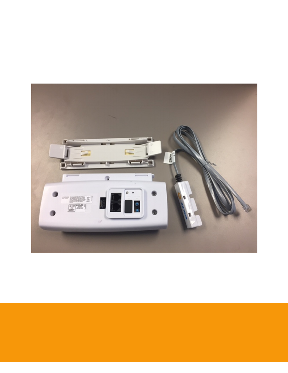
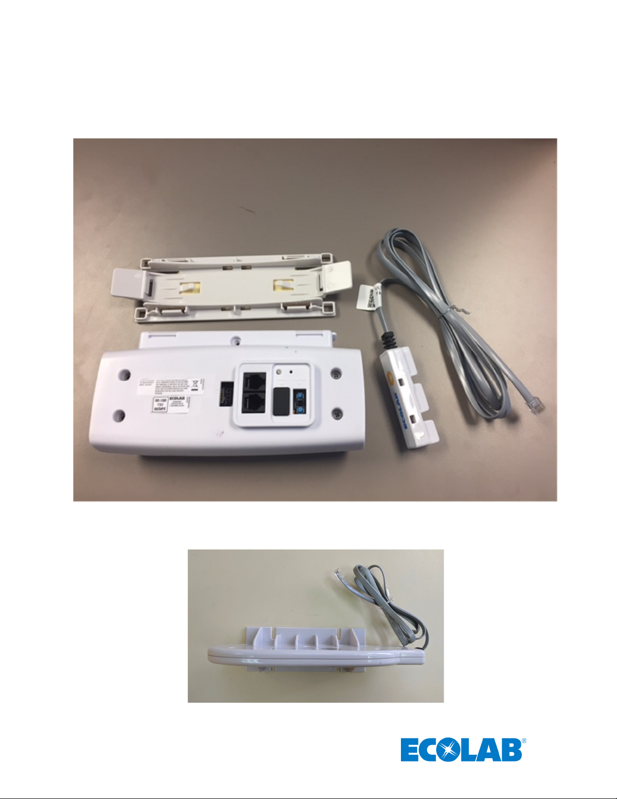
Ecolab Hand Hygiene Compliance Monitoring System: Bed Beacon, Mounting Bracket and AC Line Power Sensor
Ecolab Bed Beacon External Antenna (P/N: 92052232)
4
Page 6
B
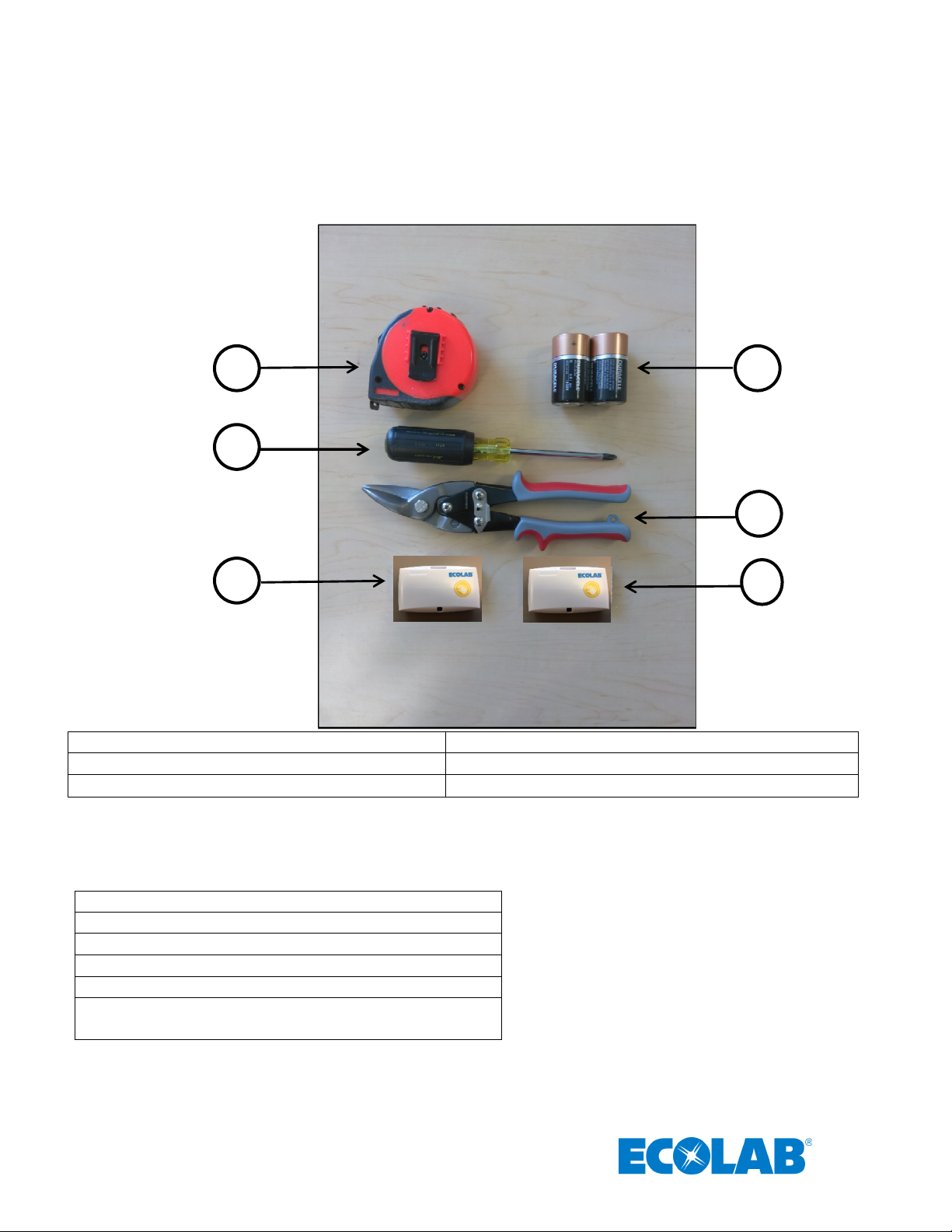
2. Required Materials
2.1 Installation Materials
A
C
D
E
(A) Tape Measure (B) Duracell Coppertop Alkaline D cell batteries (2 ea.)
(C) Phillips screwdriver (D) Wire cutters
(E) Range Test Badge with Network (F) Range Test Badge Without Network
Items not pictured:
(G) Cable Tie 4in long (10ea.)
(H) Cable Tie Holder (10ea.)
(I) Cable Tie 18in long (4ea.)
(B) Alcohol Wipe
(C) Scotch-Brite™ (or similar) scouring pad
(D) Spray bottle with a mixture of liquid dish soap and
water (1 oz. soap per gallon of water)
F
5
Page 7
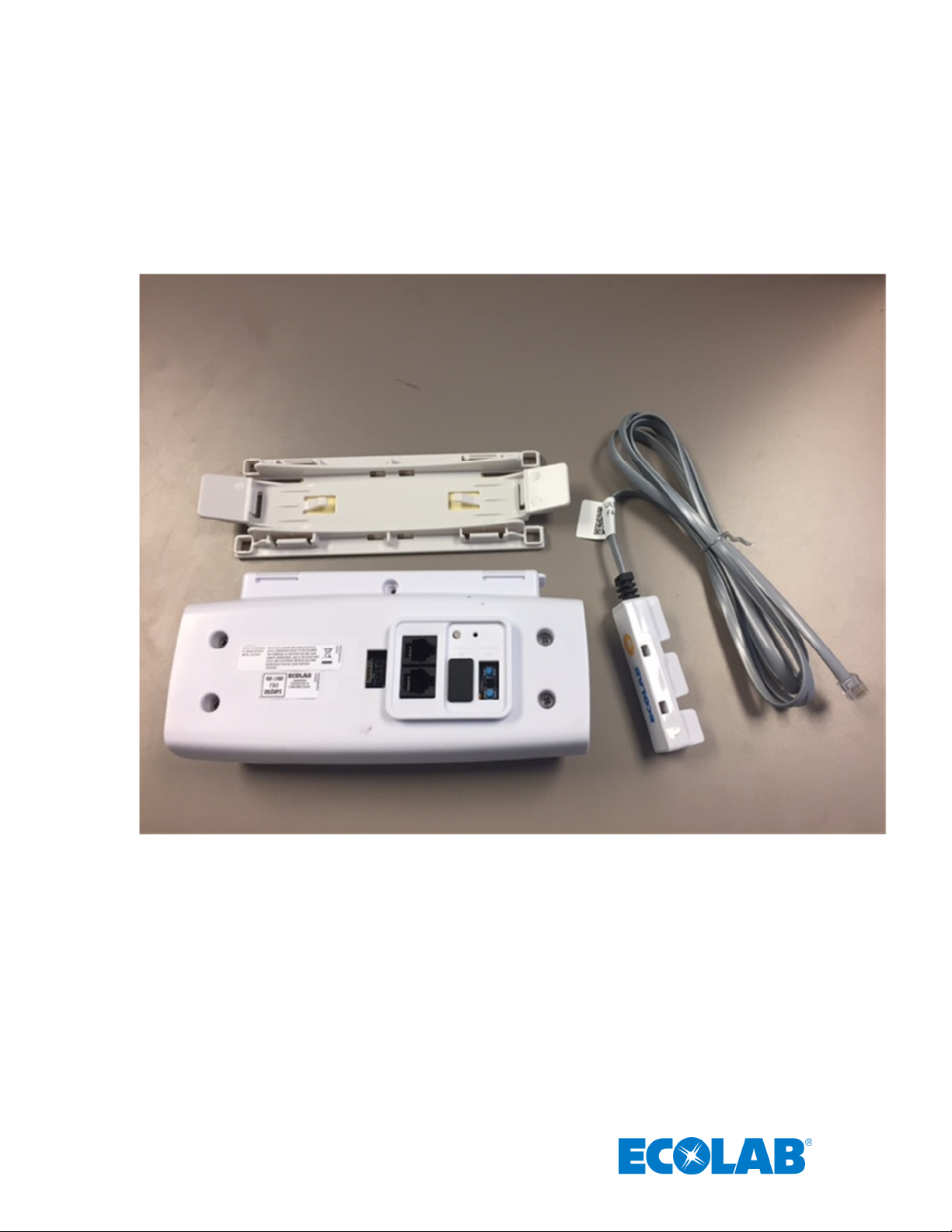
2.2 Bed Beacon Components
The patient bed installation is comprised of four main components. The first component is the Bed Beacon,
which is used to create and control the Patient Zone around the patient bed. The second component is the
AC Line Power Sensor that senses when the bed is connected (turns the Patient Zone on) or disconnected
(turns the Patient Zone off) from AC power. The third component is an External Antenna that will be
mounted on the Patient Bed and create another Patient Zone around the antenna. This antenna provided by
Ecolab is specific to this equipment and may not be replaced by any other antenna models. The last
component is the quick release Mounting Bracket clip for attaching the Bed Beacon to a bed or stretcher.
Figure 1. Bed Beacon Installation Components
3. Bed Beacon Installation Functions
The Bed Beacon creates a modulated magnetic field around a patient bed, referred to as the Patient Zone.
When a healthcare worker (HCW) wearing a System Badge enters the Patient Zone, the Bed Beacon wirelessly
communicates with the Badge and signals to the Badge that it has entered the Patient Zone around a specific
patient bed. The Bed Beacon will emit an audible beep and flash its status LED (Light Emitting Diode) green
when it has successfully communicated with a Badge. If communication with the Badge is successful, the Bed
Beacon sends information about its interaction with the Badge to the server via the System’s proprietary wireless
network. For more information about how the Badge will behave when interacting with the Patient Zone, please
read the document entitled “Ecolab™ Hand Hygiene Program Compliance Monitoring System Healthcare Worker
Badge User’s Guide”.
6
Page 8
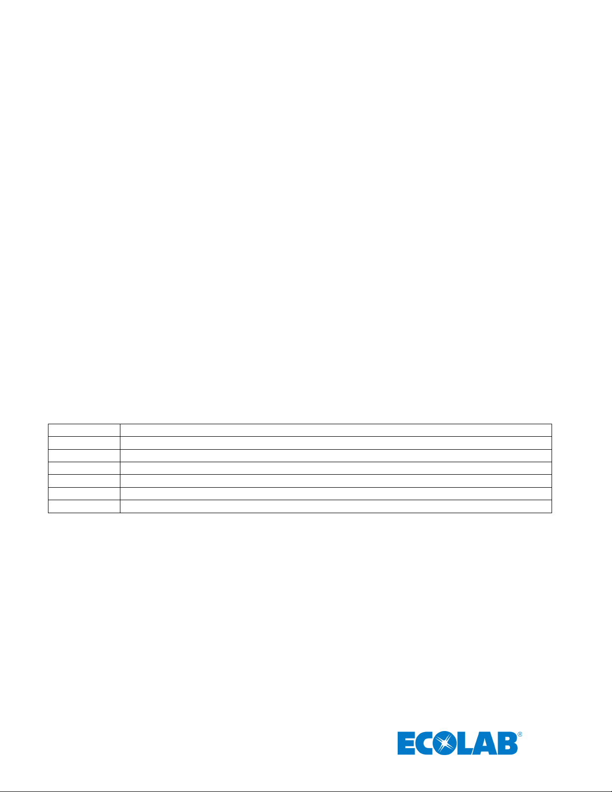
To verify which mode the Bed Beacon is in, press and hold both range buttons down. Immediately, the Beacon
*** 3 green flashes and beeps
– default NFC range, which is 10 (maximum)
* 1 red flash and beep
– operation mode 1
** 2 red flashes and beeps
– operation mode 2
*** 3 red flashes and beeps
– operation mode 3
****
4 red flashes and beeps
– operation mode 4
*****
5 red flashes and beeps
– operation mode 5
******
6 red flashes and beeps
– operation mode 6
will flash three (3) times the green LED. With each flash, there will be an audible alert (beep). If the range buttons
are released during or immediately after the three green flashes, the bed beacon is set to the default range (10 =
maximum). One (1) second later, the Bed Beacon will flash red and beep once. The single red LED flash and
audible alert corresponds to the Bed Beacon being set for mode number 1: bed mode. If both range buttons
continue to be held down, the bed beacon will continue to cycle through the operation modes, at a rate of 1 every
500 ms. The number of red LED flashes and audible beeps corresponds to the operation mode (see list below.)
In order to select the mode, release the range buttons after the desired mode is reached.
An alternative method of setting the bed mode is with the Ecolab Beacon Installation Tool (9250-3074). For
more information about how the Beacon Installation Tool can change the Beacon mode, please read the
document entitled, “Ecolab™ Hand Hygiene Program Compliance Monitoring System Beacon Installation Tool
User’s Guide”.
Operation Modes:
1 = Bed Mode using Internal Antenna Only
2 = Bed Mode using External Antenna Only
3 = Bed Mode using Internal and External Antenna (toggle between internal and external antenna)
4 = Stretcher Mode using Internal Antenna Only
5 = Stretcher Mode using External Antenna Only
6 = Stretcher Mode using Internal and External Antenna (toggle between internal and external antenna)
Note:
Bed Modes (1-3) - AC Power Cord Sensor must detect AC power to broadcast the 125kHz signal.
Stretcher Modes (4-6) – the 125kHz signal is always broadcast. No AC Power Cord Sensor required.
The default operation mode is 1. To select a different mode, press and hold both range buttons simultaneously. The LEDs
will flash and the piezo will beep to indicate the mode.
.
7
Page 9
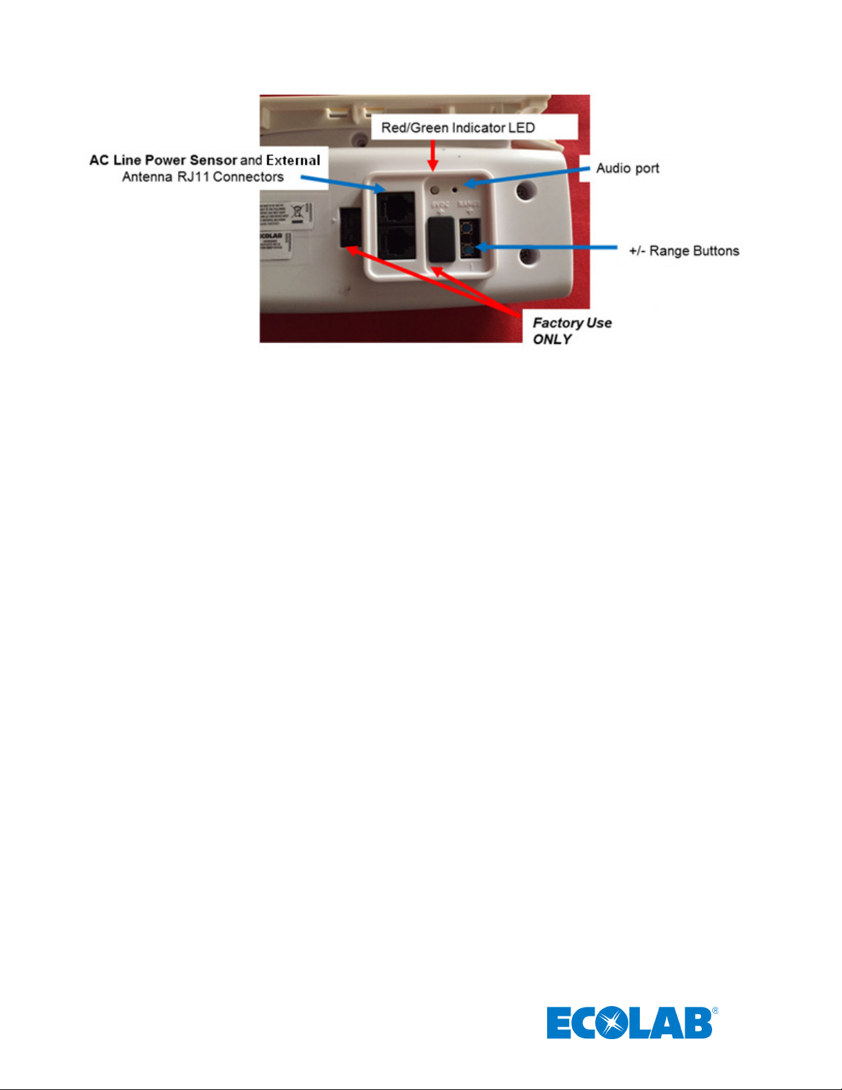
Figure 2. Bed Beacon Details
3.1 Bed Mode (Default) (Internal antenna only)
* 1 red flash and beep – operation mode 1
In “Bed Mode”, the Bed Beacon is mounted on a patient bed and connected to an AC Line Power Sensor
through either RJ11 connector. The Bed Beacon is then able to detect when the bed’s AC power cord is
connected to a wall outlet, causing the Bed Beacon to emit a beep and the LED to flash green. The state of
the AC Line Power Sensor is included in the information sent when the Bed Beacon sends out a heartbeat
message over the System’s proprietary wireless network. If the bed’s power cord is disconnected from AC
wall power, the Patient Zone will be turned off and will remain off while the bed is in transit. When the AC
Line Power (ALP) Sensor senses that the power is disconnected, the Bed Beacon will emit a beep and
flash the red LED. When the bed’s power cord is plugged in again, the Bed Beacon will emit a beep and
flash the green LED (may take up to 3S for the Bed Beacon to acknowledge the change in state).
3.2 Bed Mode, Using External Antenna Only
** 2 red flashes and beeps – operation mode 2
To set the mode, press and hold both range buttons down. Immediately, the Beacon will flash the green
LED three (3) times. With each flash, there will be an audible alert (beep). Continue to hold the range
buttons down while the bed beacon continues to cycle through the operation modes, until you reach two (2)
red LED flashes / 2 audible beeps. Release the range buttons to set.
In this mode, the patient zone is created by the External Antenna only. The Bed Beacon itself is used to
communicate with badges and the System network hubs. In “Bed Mode, External Antenna Only”, the Bed
Beacon is mounted on a patient bed and connected to the AC Line Power Sensor through either RJ11
connector. The External Antenna is connected to the Bed Beacon using the remaining RJ11 connector and
is then also attached to the bed, in a central location, as it will generate the patient zone. The External
Antenna ( Ecolab P/N: 92052232 ) provided by the Ecolab is specific to this equipment and may not be
replaced by any other antenna model. The Bed Beacon is then able to detect when the bed’s AC power
cord is connected to a wall outlet, causing the Bed Beacon to emit a beep and the LED to flash green. If the
8
Page 10

bed’s power cord is disconnected from AC wall power, the Patient Zone will be turned off and will remain off
while the bed is in transit. When the AC Line Power (ALP) Sensor senses that the power is disconnected,
the Bed Beacon will emit a beep and flash the red LED. When the bed’s power cord is plugged in again, the
Bed Beacon will emit a beep and flash the green LED.
3.3 Bed Beacon, Using Internal and External Antenna Mode (toggling back and forth
between the internal and external antenna)
*** 3 red flashes and beeps – operation mode 3
To set the mode, press and hold both range buttons down. Immediately, the Beacon will flash three (3)
times the green LED. With each flash, there will be an audible alert (beep). Continue to hold the range
buttons down while the bed beacon continues to cycle through the operation modes, until you reach three (3)
red LED flashes / 3 audible beeps. Release the range buttons to set.
In this mode, External Antenna ( Ecolab P/N: 92052232 ) is plugged into either RJ11 connector on the Bed
Beacon, and both the Bed Beacon and the External Antenna are attached to the bed. The patient zone is
created by alternating between the Internal and the External Antenna, allowing for extension of the patient
zone area. The Bed Beacon communicates with badges and the System network hubs. The AC Line Power
Sensor is connected to the Bed Beacon through the remaining RJ11 connector. The External Antenna is
connected to the Bed Beacon using the remaining RJ11 connector and is then also attached to the bed, in a
central location, as it will generate the patient zone. The Bed Beacon is then able to detect when the bed’s
AC power cord is connected to a wall outlet, causing the Bed Beacon to emit a beep and the LED to flash
green. If the bed’s power cord is disconnected from AC wall power, the Patient Zone will be turned off and
will remain off while the bed is in transit. When the AC Line Power (ALP) Sensor senses that the power is
disconnected, the Bed Beacon will emit a beep and flash the red LED. When the bed’s power cord is
plugged in again, the Bed Beacon will emit a beep and flash the green LED.
3.4 Stretcher Mode, using Internal Antenna Only
**** 4 red flashes and beeps – operation mode 4
“Stretcher Mode” is used when the Bed Beacon is mounted directly under a patient stretcher and there is no
AC Line Power Sensor connected to it. In stretcher mode, the Bed Beacon will always have the Patient
Zone “on”. To set the Bed Beacon mode, press and hold both range buttons down. Immediately, the
Beacon will flash three (3) times the green LED. With each flash, there will be an audible alert (beep).
Continue to hold the range buttons down while the bed beacon continues to cycle through the operation
modes, until you reach four (4) red LED flashes / 4 audible beeps. Release the range buttons to set.
3.5 Stretcher Mode, using External Antenna Only
***** 5 red flashes and beeps – operation mode 5
“Stretcher Mode using External Antenna” is used when the Bed Beacon and the External Antenna
( Ecolab P/N: 92052232 ) are both mounted directly under a patient stretcher and there is no AC Line Power
Sensor connected to the Bed Beacon. The External Antenna is connected to the Bed Beacon using the
remaining RJ11 connector and is then also attached to the bed, in a central location, as it will generate the
patient zone. In stretcher mode, the Bed Beacon will always have the Patient Zone “on”, but in this mode
the patient zone is created by the External Antenna only. To set the mode, press and hold both range buttons
down. Immediately, the Beacon will flash three (3) times the green LED. With each flash, there will be an
audible alert (beep). Continue to hold the range buttons down while the bed beacon continues to cycle
9
Page 11
through the operation modes, until you reach five (5) red LED flashes / 5 audible beeps. Release the range
buttons to set.
3.6 Stretcher Mode Using Internal and External Antenna Mode (toggling back and
forth between the internal and external antenna)
****** 6 red flashes and beeps – operation mode 6
“Stretcher Mode using Internal and External Antenna” is used when the Bed Beacon and the External
Antenna ( Ecolab P/N: 92052232 ) are mounted directly under a patient stretcher and there is no AC Line
Power Sensor connected to it. In this stretcher mode, the Bed Beacon will always have the Patient Zone
“on”. In this mode the patient zone is created alternatingly by the External Antenna and the Bed Beacon’s
internal antenna. This is used to extend the effective area of the patient zone. To set the mode, press and
hold both range buttons down. Immediately, the Beacon will flash three (3) times the green LED. With each
flash, there will be an audible alert (beep). Continue to hold the range buttons down while the bed beacon
continues to cycle through the operation modes, until you reach six (6) red LED flashes / 6 audible beeps.
Release the range buttons to set.
4. Installation
4.1 Mounting Bracket 9205-2337 Installation - Patient Bed
The Mounting Bracket can be mounted in the center of the lower bed frame (see Figure 3).
Figure 3. Mounting Bracket on Patient Bed Model Hill-Rom Versa Care P3200
Make sure the Mounting Bracket location surface is clean and free of dirt and oil. Spray a mixture of liquid
dish soap (1% soap per gallon of water) and scrub the mounting surface with a plain Scotch-Brite scouring
pad. Wipe the surface with a lint-free cloth to clean off any contaminants. Next, use a soft cloth dampened
with isopropyl alcohol to further clean the mounting surface. Repeat the process as necessary. Ensure that
the mounting surface is dry before attaching the Mounting Bracket. Peel off the double-sided tape liner on
the Mounting Bracket. Firmly press and hold the Mounting Bracket in place for several minutes. Secure
the Mounting Bracket with the two (2) 14 inch long cable ties, one (1) on each side of the Bracket. Finally,
flush cut off the excess cable tie ends.
2- 14” Long
Cable Ties
10
Page 12

4.2 Bed Beacon Installation
Mount
ing Bracket
Bed Beacon
Bed Beacon
Release
Remove the front battery cover, using a Phillips head screw driver. Correctly position battery polarity and
insert two new Duracell® Coppertop alkaline D cell batteries (see Figure 4). After the Bed Beacon batteries
are installed, the Bed Beacon will perform a POST (Power On Self-Test).
(a)***
(pressed). If only two green flashes, - range switch is stuck closed (pressed).
(b) Pause
(c)**** - Alternate between green and red LED 2 times (LED test)
(d) BEEP - Piezo test
(Note: If the POST LED flashes red three times, then the Bed Beacon is defective.)
Replace the Bed Beacon’s battery door and re-tighten screw. Set the Bed Beacon in the desired
Bed/Stretcher Mode.
- Three green LED flashes (Range Switch test). If only one green flash, + range switch is stuck closed
Figure 4. Installing Batteries
Figure 5. Version 1 Bed Beacon (9205-2185) Mounted on Patient Bed Model Hill-Rom Versa Care P3200
(Note: Photographs showing the mounting of the Bed Beacon on Hospital Beds will depict an earlier
version of the Bed Beacon, 9205-2185.)
Before attaching the Bed Beacon to the Mounting Bracket, position the Bed Beacon based on AC Line
Power Sensor cable management. Press the Bed Beacon (flat side) into the Bracket until a click is heard.
Pull downward on the Bed Beacon to verify that the attachment is secure.
To unclip the Beacon, push up on either Mounting Bracket tab to release (See Figure 6).
Bed Beacon Release Tab
Figure 6. Mounting Bracket Release Tabs
11
Page 13
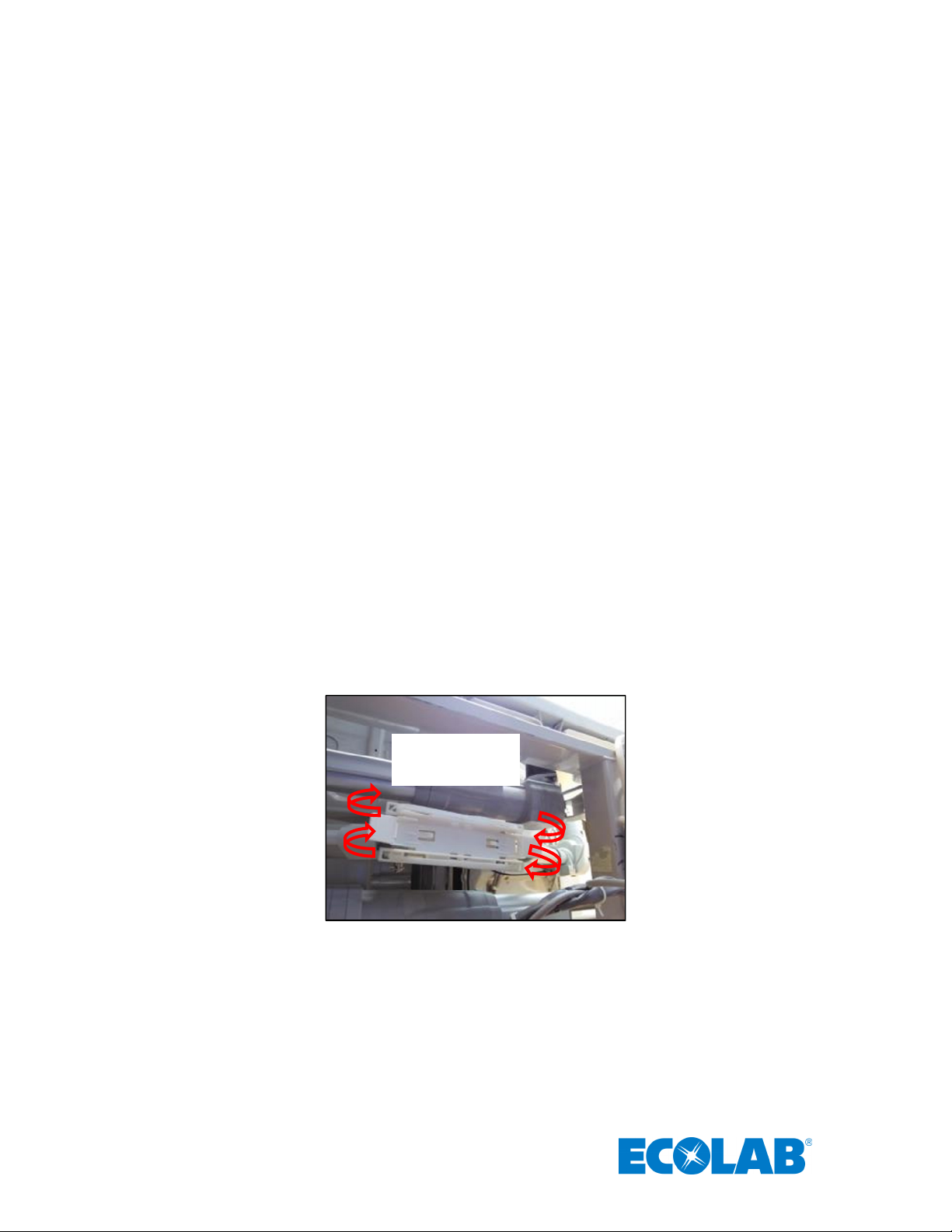
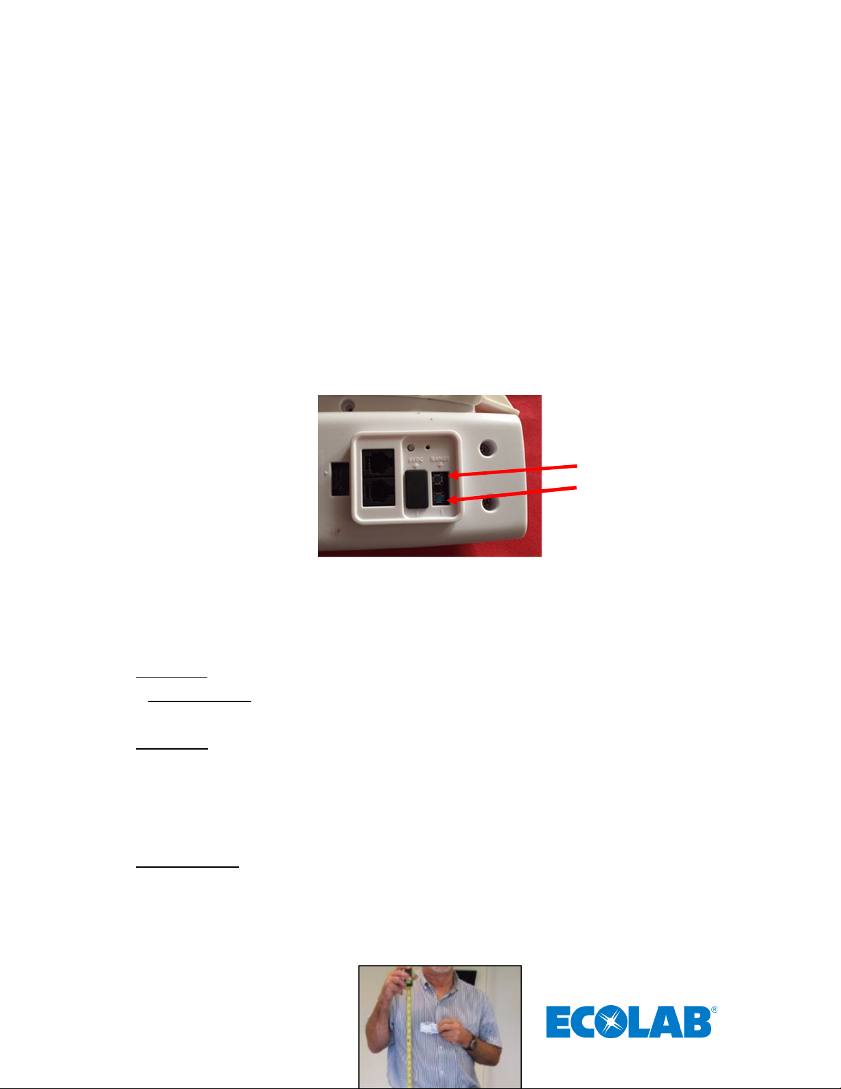
4.3 AC Line Power Sensor
AC Line Power
The AC Line Power Sensor (see Figure 7) is strapped to the bed’s AC power cord approximately three (3)
inches from the bed cord’s power connector. The AC Line Power Sensor senses if the bed is connected to
AC power, and will activate or deactivate the Bed Beacon accordingly. The AC Line Power Sensor is
connected to the Bed Beacon. It mounts to bed’s power cord with two (2) cable ties. Make sure a service
loop is left in the AC Line Power Sensor’s cable run, allowing the bed to be raised and lowered. Note:
Stretchers are installed without the AC Line Power Sensor because they don’t have an AC power cord. In
stretcher mode; the stretcher field is continuously on.
Sensor attached to
power cord
Figure 7. AC Line Power Sensor Attached to Power Cord
Cable Tie mounting
Attach the AC Line Power Sensor to the patient bed’s AC power cord using 2 cable ties (see Figure 7). Use
cable tie holders for routing the wire to the Bed Beacon, and make sure the mounting surface is clean and
free of dirt and oil. A soft cloth dampened with isopropyl alcohol works well to clean both surfaces.
Three (3)
inches
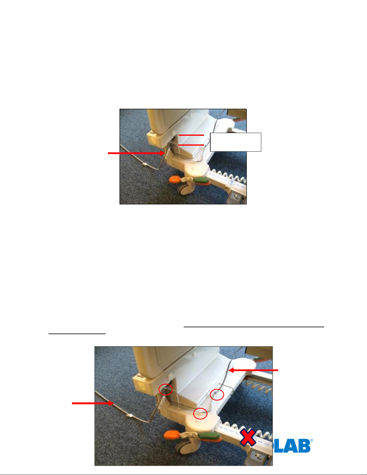
5. Cable Management – Hill Rom VersaCare P3200
1. Place cable tie holders and cable ties, then route cable to the Bed Beacon as shown (see Figure 7, 8 & 9).
Make sure the mounting surfaces are clean and free of dirt and oil. A soft cloth dampened with isopropyl
alcohol works well to clean the mounting surfaces. Avoid routing cables near the bed’s patient fall detect
sensor IR beam path.
AC Line
Cord
12
Service Loop (17”)
Page 14
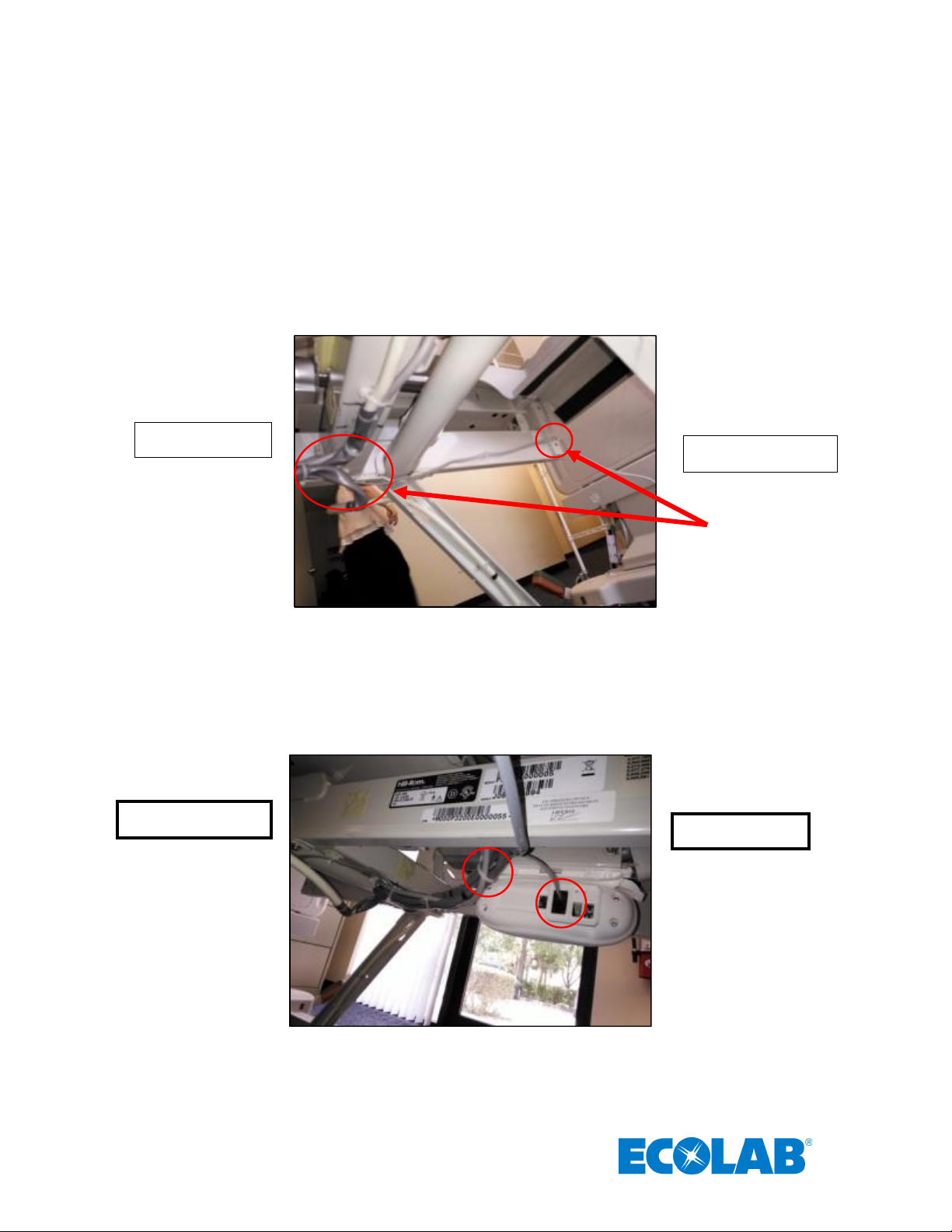
Tie Downs
Patient Fall Detect
Sensor Path
Figure 8. AC Line Power Sensor Cable Routing and Cable Tie Holder Placement
2. Place cable tie holders and route the AC Line Power Sensor cable along the inside rail and tie down any
excess cable (service loop) as shown (see Figure 8).
Foot of the bed
Head of the bed
Figure 9. AC Line Power Sensor Cable Routing and Cable Tie Holder Placement
3. Place a cable tie holder and route the AC Line Power Sensor cable as shown (see Figure 10).
Head of the bed
Foot of the bed
Figure 10. AC Line Power Sensor Cable Routing to Bed Beacon and Cable Tie Holder Placement
13
Page 15
6. Adjusting the Patient Zone
In
crement “
+“
6.1 Range Adjustment on Beds
The Bed Beacon communication range is adjusted during installation to optimize communication with the
healthcare worker Badge. To adjust the communication range, remove the rubber range cover (see Figure
11) located on the back of the Bed Beacon. After the range cover has been removed, the Bed Beacon
communication range is adjusted by repeatedly pushing either the “+” increment or the “–“ decrement range
buttons (see Figure 11) to achieve the desired range. The total adjustable range of the Bed Beacon is from
1 to 10 increments between the lowest and the highest setting. Each push of the “+” button will produce an
audible beep and the green LED will flash once indicating one (1) increment up. When the highest setting is
reached, two (2) audible beeps will be heard and two (2) green LED flashes will be visible. Each push of the
“-” button will produce an audible beep and the red LED will flash once indicating one (1) increment down.
When the lowest setting is reached, two (2) audible beeps will be heard and two (2) red LED flashes will be
visible. To reset a Bed Beacon’s range back to the factory default setting, push and hold both the “+” and
“-“ buttons at the same time. Three (3) audible beeps will be heard and the LEDs will simultaneously flash
green three (3) times. The factory default range setting for the Bed Beacon is position 10. Replace the
range button cover when the adjustment is complete.
Decrement “-”
Figure 11. Bed Beacon Range Adjustments
6.2 Test Badge Range Adjustment
1. Bed Installs - Adjust the bed and mattress height to the average height for beds in the facility.
Stretcher Installs - Adjust the stretcher and mattress height to the average height for stretchers in the
facility.
2. Bed Installs - While holding the Test Badge (without Network) 50 inches from the floor and 18 inches
from the bed’s handrail center location (side of bed) (see Figures 12 & 13), the Test Badge’s green and
yellow LEDs should flash once a second, indicating that the proper activation range and communication
have been successfully established. If range is not 18” adjust the Bed Beacon’s range buttons until the
Badge activation range is 18 inches (see Figure 12). Once the range has been set, use the Test Badge
(with Network) to verify the Bed Beacon communication to the Proprietary wireless network by
placing the Badge in the field.
Stretcher Installs - While holding the Test Badge (Network) 50 inches from the floor (Figure 12) and at
the edge of the stretcher handrail center location (side of stretcher), the Test Badge’s green and yellow
LEDs should flash once a second, indicating that the proper activation range and communication have
been successfully established. If range is not at the edge of the handrail adjust the Bed Beacon’s
range buttons until the Badge activation range is at the edge. Once the range has been set, use the
Test Badge (with Network) to verify the Bed Beacon communication to Network by placing the Badge
in the field.
14
Page 16

Figure 12. Test Badge Height Is 50 Inches From the floor
Figure 13. Test Badge Activation Distance from Bed’s Handrail Center is 18” (at edge for stretcher installations)
6.3 Ecolab Dashboard Test with the Network Badge and Bed Beacon
If needed, please refer to “Ecolab™ Hand Hygiene Program Compliance Monitoring System Dashboard
Directions for Use” for further information on how to use the Dashboard.
1. Using a HCW Badge, verify that the Bed Beacon and Badge activate at 18 x 50 inches. Also verify that
the Bed Beacon’s device address appears on the Dashboard.
2. Using a web browser, type the facility’s Dashboard URL and you should see login screen shown in
Figure 14.
3. Type in the correct email address and password to login to the Dashboard.
Figure 14. Dashboard Entry Screen
4. When access is granted you should see the screen shown in Figure 15.
15
Page 17

Figure 15. Main Dashboard Page
5. Click on “System Menu” under the System Tab as shown in Figure 16.
Figure 16. Choose System Menu Screen
6. Click on Bed Beacons and a list of all current active Bed Beacons will be displayed as shown in Figure
17.
Figure 17. System Menu Screen
Search Box
16
Page 18

Figure 18. Search for Bed Beacon address
Result
7. Enter the Bed Beacon’s device address number as shown in Figure 18 and click the enter key. The list
will automatically display the results.
Figure 19. Device Screen Results
8. If the Bed Beacon address appears in the results and has a recent “Ping Time”, this confirms that the
Bed Beacon successfully communicated with the Network (see Figure 19). If the Bed Beacon address
does not appear in the results, retest with a Badge.
There may be circumstances which require a Bed Beacon’s range to be adjusted, after the initial
installation, to properly communicate with a Badge. Examples of why a Bed Beacon’s range may need to
be adjusted are explained below.
Cases for Bed Beacon Range Adjustment
Last
Ping
1. Two beds with Bed Beacons in one room.
2. Two beds with Bed Beacons in separate but adjacent rooms separated by a wall.
In both cases, the range of communication of a given Bed Beacon may overlap or interfere with a nearby
Bed Beacon. If this occurs, the HCW’s Badge may communicate with a nearby Bed Beacon instead of the
intended Bed Beacon. This miscommunication can result in the System reporting contact with the wrong
patient. To eliminate the possibility of miscommunication, the range of Bed Beacons in close proximity may
be decreased, at any time, to ensure that a HCW’s Badge will communicate with the intended Bed Beacon.
7. Metadata Entry
7.1 New Bed Beacon Metadata Entry
Activate the Bed Beacon with a Badge, twice, at the hospital. The events will be transmitted to the server to
be viewed on the Dashboard. To locate the active Bed Beacon, login to the Dashboard and select the
“Bed Beacon” option under the System menu.
The metadata can only be accessed by restricted logins. Read the Bed Beacon address on the product
label. The Bed Beacon’s hexadecimal address will start with a 1E. The 1E at the beginning of the address
is the device type and tells the Dashboard that this is a Bed Beacon. Enter the full address into the
“Address” column search window. In the example below, the address is 1E000767 (see Figure 20). Click the
“Click to Edit Device” icon under the “State” column to open the device’s metadata page.
17
Page 19

1E000767
Figure 20. Active Bed Beacon List
• Device Information (see Figure 21)
The Bed Beacon device information is optional. The device information can be found on the product
label. An example from the product label can be located on the same page (see Figure 21)
• Bed Type: example – “Hill Rom/VersaCare” (optional metadata). The bed manufacturer and model
information can assist staff in identifying a bed
• Bed Number: example – “001” (required metadata). The installer can choose to place a numbered label at
the bed’s footboard frame to easily identify beds since the Bed Beacon label may not be in a convenient
location to easily view.
• Bed Serial Number: example – “123456” (optional metadata). The bed serial number information can
assist staff in identifying a bed.
• State:
o Active- Device is currently active within the System.
o Inactive- Device will be removed from any reports.
o RMA- Repair
Figure 21. Bed Beacon Metadata
7.2 Replacing an Existing Bed Beacon – Swapping Metadata
Remove the Bed Beacon and read the address from the product label. Select the “Replace Device” function
under system menu (see Figure 22). The replacement tab will open as shown in Figure 23. Enter or scan via
bar code reader the old Bed Beacon’s address into the first box labeled “old device address”. Next, enter or
scan via bar code reader the new Bed Beacon’s address into the second box labeled “new device address”.
Finally, click the “submit button” to complete replacing the existing Bed Beacon.
18
Page 20

Figure 22. Replace Device
Figure 23. Replace Device Tab
8. Troubleshooting
8.1 No Bed Beacon Heartbeats on the Dashboard
If the Bed Beacon has stopped transmitting heartbeats to the Dashboard, there are three possible causes:
1. The batteries have died. Place a new Duracell Coppertop alkaline D set of batteries in the Bed Beacon
and test the Bed Beacon’s other function, communications with a Badge as described in section 6.3. If
the unit tests well, then give the Bed Beacon a couple of hours to transmit a few heartbeats to the
Dashboard.
2. If new batteries do not fix the problem, there may be a problem with the Bed Beacon hardware. Remove
and replace the Bed Beacon. Refer to section 7.2 – Replacing an Existing Bed Beacon – Swapping
Metadata -- for instructions on how to replace/update device information on the Dashboard.
3. If replacing the Bed Beacon does not remedy the problem, there may be a problem with the Network
Contact your Ecolab representative for further assistance.
8.2 The Bed Installation Does Not Communicate with a Badge
Verify that the bed’s AC power cord is plugged into an active power source and that the AC Line Power
Sensor is connected to the bed’s power cord.
Note: If any of the components of the Bed Installation are replaced, the bed’s range will have to be re-
checked and readjusted as needed.
19
Page 21

9. System Component Care and Maintenance
9.1 Cleaning the Components
The components may be cleaned by wiping with a soft cloth. The cloth should be damp but not wet. A soft
cloth dampened with isopropyl alcohol works well to clean the external surfaces. Only the exterior of the
components may be cleaned. Do not attempt to clean any interior surface of these components as this will
damage the component’s circuitry. Do not use abrasive cleaners or cleaning products in aerosol cans as
they will damage the component’s finish.
9.2 Handling the Bed Beacon
The Bed Beacon is an electronic device and should be handled with care. Like other electronic devices such
as cell phones, the Bed Beacon must be protected from extreme heat, cold and moisture. Avoid handling
the Bed Beacon with wet hands or exposing it to rain. Avoid dropping or tossing the Bed Beacon. The
shock can damage the Beacon’s sensitive internal electronics.
9.3 Replacement Batteries
Replacement batteries for Bed Beacons must be Duracell® Coppertop™ alkaline D batteries. Use of any
other brand batteries will result in suboptimal performance.
Appendix A - Certification and Safety Approvals
FCC Statement
NOTE: This equipment has been tested and found to comply with the limits for a Class B digital device, pursuant to Part 15
of the FCC Rules. These limits are designed to provide reasonable protection against harmful interference in a residential
installation. This equipment generates, uses, and can radiate radio frequency energy and, if not installed and used in
accordance with the instructions, may cause harmful interference to radio communications. However, there is no
guarantee that interference will not occur in a particular installation. If this equipment causes harmful interference to radio
or television reception, which can be determined by turning the equipment off and on, the user is encouraged to try and
correct the interference by one or more of the following measures:
• Reorient or relocate the receiving antenna.
• Increase the separation between the equipment and receiver.
• Connect the equipment into an outlet on a circuit different from that to which the receiver is connected.
• Consult the dealer or an experienced radio/TV technician for help.
WARNING: Changes or modifications not expressly approved by Ecolab could void the user’s authority to operate the
equipment.
The antenna provided by the manufacturer is specific to this equipment and may not be replaced by any other antenna
models.
RF EXPOSURE:
“This equipment complies with FCC radiation exposure limits set forth for an uncontrolled environment. This equipment
should be installed and operated with minimum distance 20cm between the radiator and your body. This transmitter must
not be co-located or operating in conjunction with any other antenna or transmitter.”
20
Page 22

Industry Canada
Under Industry Canada regulations, this radio transmitter may only operate using an antenna of a type and maximum (or
lesser) gain approved for the transmitter by Industry Canada. To reduce potential radio interference to other users, the
antenna type and its gain should be so chosen that the equivalent isotropically radiated power (e.i.r.p.) is not more than
that necessary for successful communication.
This device complies with Industry Canada license-exempt RSS standard(s). Operation is subject to the following two
conditions: (1) this device may not cause interference, and (2) this device must accept any interference, including
interference that may cause undesired operation of the device.
This radio transmitter (IC:10060A-92053072) has been approved by Industry Canada to operate with the antenna types
listed below with the maximum permissible gain and required antenna impedance for each antenna type indicated.
Antenna types not included in this list, having a gain greater than the maximum gain indicated for that type, are strictly
prohibited for use with this device.
Le présent émetteur radio (IC:10060A-92053072) a été approuvé par Industrie Canada pour fonctionner avec les
types d'antenne énumérés ci-dessous et ayant un gain admissible maximal et l'impédance requise pour chaque type
d'antenne. Les types d'antenne non inclus dans cette liste, ou dont le gain est supérieur au gain maximal
indiqué, sont strictement interdits pour
l'exploitation de l'émetteur.
Magnetic Loop Antenna
Ceramic Chip Antenna: -2.5 dBi
RF Exposure: This equipment complies with Industry Canada radiation exposure limits set forth for an Uncontrolled
environment. This equipment should be installed and operated with minimum distance 20cm between the radiator and
your body. This transmitter must not be co-located or operating in conjunction with any other antenna or transmitter.
Exposition aux radiofréquences : Cet équipement est conforme aux limites d’exposition par rayonnements définies par
l’industrie du Canada pour une utilisation dans un environnement non clos. Cet équipement doit être utilisé à une distance
minimale de 20 cm entre l’émetteur de radiation et votre corps. Cet émetteur ne doit pas être situe au même endroit qu’un
autre émetteur et ne doit pas être connecté à une antenne différente.
The antenna provided by the manufacturer is specific to this equipment and may not be replaced by any other antenna
models.
L'antenne fournie par le fabricant est spécifique à cet équipement et ne peut pas être remplacée par aucun autre modèle
d'antenne..
Appendix C – Bed Label
The bed label (see Figure 1) is a unique bed number that will be linked to the Ecolab Dashboard Bed Beacon
metadata. During installation, the bed labels are located on or near the foot-board frame of the patient bed (see
Figure 2). The bed number helps to quickly identify the Bed Beacon address that is on the bed.
21
Page 23

Figure
1. Bed Installation Label
Figure 2. Bed Label Location
22
Page 24

Appendix D- Z Bracket (9205-2236)
Figure 1.
Z Bracket
Figure 2.
Mounting the
Z
The Z Bracket (see Figure 1) is an optional mounting brace for the Bed Beacon to be mounted onto the
VersaCare model bed. The Z Bracket helps to elevate the Bed Beacon from the ground when the bed is at its
lowest point.
Mounting
Mount the Z Bracket under the bed on the metal surface shown in Figure 2 with double-sided tape and cable tie.
Make sure the mounting surface is clean and free of dirt and oil. First, spray a mixture of liquid dish soap (1% of
soap per gallon of water) and scrub the mounting surface with a plain Scotch-Brite scouring pad. Wipe the surface
with a lint free cloth to clean off any contaminants. Second, use a soft cloth dampened with isopropyl alcohol to
further clean the mounting surface. Repeat the process as necessary. Ensure the mounting surface is dry before
attaching the Z Bracket and firmly push and hold in place for several minutes (see Figure 2). Once the Z Bracket
is firmly mounted, secure the Bracket by cable tying it to the bed frame (see Figure 2), use small wire cutters to
carefully flush cut off and dispose of all cable tie ends. Finally, place the Bed Beacon onto the Z Bracket as
shown in Figure 2 with double-sided tape.
Bed Beacon
Cable Tie
23
Page 25

Appendix E - Patient Bed Hill-Rom Advanta Installation
24
Page 26

1. Installation
AC Line Power
1.1 Step 1: Bed Mode Configuration
Install 2 Duracell Coppertop alkaline D cell batteries into the Bed Beacon. The Bed Beacon needs to be
configured to bed mode before installing the Bed Beacon onto the bed. To verify the Beacon’s mode, hold
both range buttons down. Immediately, the Beacon will alternate four (4) times between green and red
flashes. With each flash, there will be an audio alert. Two (2) seconds later, the Bed Beacon should flash
green and beep once. The green flash and audio alert confirms that the Beacon is set for bed mode. If there
is one (1) red LED flash and one (1) beep, the Bed Beacon was already in bed mode and is now in stretcher
mode. Repeat the process to get the Bed Beacon back into bed mode.
1.2 Step 2: Installing the Bed Beacon (92053072)
The patient bed must be raised to a height of 32 inches from the floor to gain access to all the mounting
locations.
Bed Beacon mounting
Mount the Bed Beacon underneath the bed frame with double-sided tape as shown in Figure 1. Make sure
the Bed Beacon and the mounting surface are clean and free of dirt and oil. A soft cloth dampened with
isopropyl alcohol works well to clean both surfaces. Firmly push and hold in place for several minutes (see
Figure 1).
Centered
Head of the bed
Figure 1. Bed Beacon Installation Location on the Bed
Foot of the bed
1.3 Step 3: Installing the AC Line Power Sensor on the Bed’s AC Power Cord
The AC Line Power Sensor (see Figure 2) is mounted onto the bed’s gray AC power cord located
underneath the bed. Use the supplied cable ties to secure the AC Line Power Sensor to the bed’s power
cord as shown. The Bed Beacon Patient Zone is only enabled when the Sensor detects AC power on the
bed’s line cord after it is plugged into an AC outlet. The Bed Beacon Patient Zone will be disabled while the
bed is unplugged. The Bed Beacon will send heartbeats in both the enabled and disabled modes.
Sensor attached to
the bed’s power cord
25
Page 27

Figure 2.
The
AC Line Power Sensor
Installation Location on
Figure 3.
Connecting the
AC Line Power Sensor
to the Bed Beacon via the RJ11 connector
AC Line Power
Bed
the Bed
1.4 Step 4: Adjusting the Bed Beacon to Proper Field Range
1. Connect the AC Line Power Sensor to the Bed Beacon via any RJ11 jacks as shown in Figure 3.
2. Plug the patient bed’s AC power cord into a 120vAC power source. This will activate the Bed Beacon so
that the range setting and all testing can be performed. Refer to section 6 - Adjusting the Patient Zone -- in
the main section of this document for instructions on adjusting the communication range.
AC Line Power
Sensor Cable RJ11
connectors
2. Cable Management
2.1 Step 5: AC Line Power Sensor Cable Routing
1. Place cable tie holders, cable ties and route AC Line Power Sensor cable to the Bed Beacon as shown
(see Figure 4 & 5). Make sure the mounting surfaces are clean and free of dirt and oil. A soft cloth
dampened with isopropyl alcohol works well to clean mounting surfaces.
Beacon
26
Cable
Head of the bed Foot of the bed
Sensor attached to
power cord
Page 28

1. For installation adjust the bed mattress height to 32 inches
2. For safetly reasons disconnect the bed AC power cord from
120vAC source
3. Step 1
- Bed Beacon
Mode Configuration
4. Step 2
- Installing the Bed Beacon (
9205
3072
)
5. Step 3
- Install the AC Line Power Sensor (
9205
-
2186
)
Figure 4.
AC Line Power Sensor
Cable Routing to the
Bed Beacon
Figure 5.
AC Line Power Sensor
Cable Routing
Bed
2. Route the AC Line Power Sensor cable underneath the headboard along the metal rail frame. Secure the
cable with cable ties shown in Figure 4 & 5.
Cable
Head of the bed
3. Place cable tie holders, route and tie down any excess cable from the AC Line Power Sensor as shown
(see Figure 5). After all cable management is complete, use small wire cutters to carefully flush cut off and
dispose of all cable tie ends.
Beacon
Foot of the bed
3. Step 6: Final Test
3.1 Disconnect and Reconnect the Bed’s AC Power Cord
Confirm that the bed’s AC power cord is connected into a 120vAC power source. Disconnect the bed’s AC
power cord and within 5 seconds you will hear one beep and the Bed Beacon LED will flash red once.
Reconnect the bed’s AC power cord and within 5 seconds you will hear one beep and the Bed Beacon LED
will flash green once. This will confirm that everything is working properly. Complete the installation by
following the instructions on metadata entry in section 7 – Metadata Entry -- in the main section of this
document.
4. Bed Installation Checklist
Organize all required equipment & tools
27
Page 29

6. Step 4
- Adjusting the Bed Beacon to Proper Field Range Refer
to section 6
7. Step 5
-
AC Line Power
Sensor Cable Management
8. Step 6
- Final Test: Disconnect and Reconnect the Bed’s AC Power Cord
9. Step 7
- Metadata Entry
Appendix F - Patient Bed Hill-Rom 1000 & Advanta 2 Installation
28
Page 30

1. Installation
1.1 Step 1: Bed Mode Configuration
Install 2 Duracell Coppertop alkaline D cell batteries into the Bed Beacon. The Bed Beacon needs to be
configured to bed mode before installing the Bed Beacon onto the bed. To verify the Beacon’s mode, hold
both range buttons down. Immediately, the Beacon’s LED will alternate four (4) times between green and
red flashes. With each flash, there will be an audio alert. Two (2) seconds later, the Bed Beacon should
flash green and beep once. The green flash and audio alert confirms that the Beacon is set for bed mode. If
29
Page 31

there is one (1) red LED flash and one (1) beep, the Bed Beacon was already in bed mode and is now in
AC Line Power
Figure 2.
The AC Line Power Sensor
Installation Location on the Bed
stretcher mode. Repeat the process to get the Bed Beacon back into bed mode.
1.2 Step 2: Installing the Bed Beacon (92053072)
The patient bed must be raised to a height of 32 inches from the floor to gain access to all of the mounting
locations.
Bed Beacon mounting
Mount the Bed Beacon on the center rail and secure the Bed Beacon with two 18" natural cable ties as
shown in Figure 1. Make sure the Bed Beacon and the mounting surface are clean and free of dirt and oil. A
soft cloth dampened with isopropyl alcohol works well to clean both surfaces.
Head of the bed
Figure 1. Bed Beacon Installation Location on the Bed
18" natural cable ties
Foot of the bed
1.3 Step 3: Installing the AC Line Power Sensor on the Bed’s AC Power Cord
The AC Line Power Sensor (see Figure 2) is mounted onto the bed’s black AC power cord located
underneath the bed. Use the supplied cable ties to secure the AC Line Power Sensor to the bed’s power
cord as shown. The Bed Beacon Patient Zone is only enabled when the Sensor detects AC power on the
bed’s line cord after it is plugged into an AC outlet. The Bed Beacon Patient Zone will be disabled while the
bed is unplugged. The Bed Beacon will send heartbeats in both the enabled and disabled modes.
Sensor attached to
the bed’s power cord
30
Page 32

AC Line Power
Figure 3.
Connecting the
AC Line Power Sensor
to the
Bed Beacon
via the RJ11 connector
Figure 4.
AC Line Power Sensor
Cable Routing to the
Bed Beacon
AC Line Power Sensor
1.4 Step 4: Adjusting the Bed Beacon to Proper Field Range
1. Connect the AC Line Power Sensor to the Bed Beacon via any RJ11 jack as shown in Figure 3.
2. Plug the patient bed’s AC power cord into a 120vAC power source. This will activate the Bed Beacon so
that the range setting and all testing can be performed. Refer to section 6 - Adjusting the Patient Zone in the
main section of this document for instructions on adjusting the communication range.
Cable RJ11 Connectors
2. Cable Management
2.1 Step 5: AC Line Power Sensor Cable Routing
1. Place cable tie holders, cable ties and route AC Line Power Sensor cable to the Bed Beacon as shown
(see Figure 4 & 5). Make sure the mounting surfaces are clean and free of dirt and oil. A soft cloth
dampened with isopropyl alcohol works well to clean mounting surfaces.
Sensor attached to
power cord
31
Cable Tie
Holders
Page 33

1. For installation adjust the bed mattress height to 32 inches
2. For safetly reasons disconnect the bed AC power cord from
120vAC source
3. Step 1
- Bed Beacon
Mode Configuration
4. Step 2
- Installing the Bed Beacon (
9205
3072
)
5. Step 3
- Install the AC Line Power Sensor (
9205
-
2186
)
6. Step 4
- Adjusting the Bed Beacon to Proper Field Range Refer to
section 6
7. Step 5
-
AC Line Power
Sensor Cable Management
8. Step 6
- Final Test: Disconnect and Reconnect the Bed’s AC Power Cord
9. Step 7
- Metadata Entry
Figure 5.
AC Line Power Sensor
Cable Routing
2. Route the AC Line Power Sensor cable underneath the bed along the metal rail frame. Secure the cable
with cable ties shown in Figure 4 & 5.
Cable Ties
3. Place cable tie holders, route and tie down any excess cable from the AC Line Power Sensor as shown
(see Figure 5). After all cable management is complete, use small wire cutters to carefully flush cut off and
dispose of all cable tie ends.
3. Step 6: Final Test
3.1 Disconnect and Reconnect the Bed’s AC Power Cord
Confirm that the bed’s AC power cord is connected into a 120vAC power source. Disconnect the bed’s AC
power cord and within 5 seconds you will hear one beep and the Bed Beacon LED will flash red once.
Reconnect the bed’s AC power cord and within 5 seconds you will hear one beep and the Bed Beacon LED
will flash green once. This will confirm that everything is working properly. Complete the installation by
following the instructions on metadata entry in section 7 – Metadata Entry in the main section of this
document.
4. Bed Installation Checklist
Organize all required equipment & tools
32
Page 34

Appendix G - Patient Bed Stryker Installation
33
Page 35

1. Installation
1.1 Step 1: Bed Mode Configuration
Install 2 Duracell Coppertop alkaline D cell batteries into the Bed Beacon. The Bed Beacon needs to be
configured to bed mode before installing the Bed Beacon onto the bed. To verify the Beacon’s mode, hold
both range buttons down. Immediately, the Beacon will alternate four (4) times between green and red
flashes. With each flash there will be an audio alert. Two (2) seconds later, the Bed Beacon LED should
flash green and beep once. The green flash and beep confirms that the Beacon is set for bed mode. If there
is one (1) red LED flash and one (1) beep, the Bed Beacon was already in bed mode and is now in stretcher
mode. Repeat the process to get the Bed Beacon back into bed mode.
1.2 Step 2: Installing the Bed Beacon (92053072)
The patient bed must be raised to a height of 32 inches from the floor to gain access to all the mounting
locations.
Bed Beacon mounting
Mount the Bed Beacon directly
double-sided tape as shown in
and the mounting surface are clean and free of dirt and oil. A soft
cloth dampened with isopropyl alcohol works well to clean both
surfaces.
underneath the bed’s headboard with
Figure 1. Make sure the Bed Beacon
34
Page 36

AC Line Power
Figure 2.
The
AC Line Power Sensor
Installation Location on the Bed
AC Line Power
Figure 1. Bed Beacon Installation Location on the Bed
Bed Beacon
1.3 Step 3: Installing the AC Line Power Sensor on the Bed’s AC Power Cord
The AC Line Power Sensor (see Figure 2) is mounted onto the bed’s black AC power cord located
underneath the bed. Use the supplied cable ties to secure the AC Line Power Sensor to the bed’s power
cord as shown. The Bed Beacon field is only enabled when the Sensor detects AC power on the bed’s line
cord after it is plugged into an AC outlet. The Bed Beacon field will be disabled while the bed is unplugged.
The Bed Beacon will send heartbeats in both the enabled and disabled modes.
Sensor attached to
the bed’s power cord
1.4 Step 4: Adjusting the Bed Beacon to Proper Field Range
1. Connect the AC Line Power Sensor to the Bed Beacon via any RJ11 jacks as shown in Figure 3.
Sensor Cable RJ11
Connectors
35
Page 37

AC Line Power Sensor
Figure 3. Connecting the
AC Line
Power Sensor
to the
Bed Beacon
via the RJ11 connector
Figure 4.
AC Line Power Sensor
Cable Routing to the
Bed Beacon
2. Plug the patient bed’s AC power cord into a 120vAC power source. This will activate the Bed Beacon so
that the range setting and all testing can be performed. Refer to section 6 - Adjusting the Patient Zone in the
main section of this document for instructions on adjusting the communication range.
2. Cable Management
2.1 Step 5: AC Line Power Sensor Cable Routing
1. Place cable tie holders, cable ties and route AC Line Power Sensor cable to the Bed Beacon as shown
(see Figure 4 & 5). Make sure the mounting surfaces are clean and free of dirt and oil. A soft cloth
dampened with isopropyl alcohol works well to clean mounting surfaces.
2. Route the AC Line Power Sensor cable underneath the headboard along the metal rail frame. Secure the
cable with cable ties shown in Figure 4 & 5.
Cable
Ties
Cable
Ties
attached to power cord
36
Page 38

1. For installation adjust the bed mattress height to 32 inches
2. For safetly reasons disconnect the bed AC power cord from 120vAC source
3. Step 1
- Bed Beacon
Mode Configuration
4. Step 2
-
Installing the Bed Beacon (
9205
3072
)
5. Step 3
- Install the AC Line Power Sensor (
9205
-
2186
)
6. Step 4
- Adjusting the Bed Beacon to Proper Field Range Refer to section 6
7. Step 5
-
AC Line Power Sensor Cable Management
8. Step 6
- Final Test: Disconnect and
Reconnect the Bed’s AC Power Cord
9. Step 7
- Metadata Entry
Figure 5.
AC Line Power Sensor
Cable Routing
3. Place cable tie holders, route and tie down any excess cable from the AC Line Power Sensor as shown
(see Figure 5). After all cable management is complete, use small wire cutters to carefully flush cut off and
dispose of all cable tie ends.
3. Step 6: Final Test
3.1 Disconnect and Reconnect the Bed’s AC Power Cord
Confirm that the bed’s AC power cord is connected into a 120vAC power source. Disconnect the bed’s AC
power cord and within 5 seconds you will hear one audio alert and the Bed Beacon LED will flash red once.
Reconnect the bed’s AC power cord and within 5 seconds you will hear one audio alert and the Bed Beacon
LED will flash green once. This will confirm that everything is working properly. Complete the installation by
following the instructions on metadata entry in section 7 – Metadata Entry in the main section of this
document.
4. Bed Installation Checklist
Organize all required equipment & tools
37
Page 39

Appendix H - Patient Bed Hill-Rom TotalCare Installation
38
Page 40

Bed Beacon
1. Installation
1.1 Step 1: Bed Mode Configuration
Install 2 Duracell Coppertop alkaline D cell batteries into the Bed Beacon. The Bed Beacon needs to be
configured to bed mode before installing the Bed Beacon onto the bed. To verify the Beacon’s mode, hold
both range buttons down. Immediately, the Beacon will alternate four (4) times between green and red
flashes. With each flash there will be an audio alert. Two (2) seconds later, the Bed Beacon should flash
green and beep once. The green flash and audio alert confirms that the Beacon is set for bed mode. If there
is one (1) red LED flash and one (1) beep, the Bed Beacon was already in bed mode and is now in stretcher
mode. Repeat the process to get the Bed Beacon back into bed mode.
1.2 Step 2: Installing the Bed Beacon (92053072)
The patient bed must be raised to a height of 32 inches from the floor to gain access to all of the mounting
locations.
Bed Beacon mounting
Mount the Bed Beacon, with double-sided tape, centered (10in x 9in) under the bed on the plastic surface
as shown in Figure 1. Make sure the Bed Beacon and the mounting surface are clean and free of dirt and
oil. A soft cloth dampened with isopropyl alcohol works well to clean both surfaces. Firmly push and hold in
place for several minutes (see Figure 2).
Centered 10in x 9in
Figure 1 & 2. Bed Beacon Installation Location on the Bed
39
Page 41

1.3 Step 3: Installing the AC Line Power Sensor on the Bed’s AC Power Cord
AC Line Power Sensor
Figure 3.
The AC Line Power Sensor
Installation Location on the Bed
Figure 4. Connecting the
AC Line Power Sensor
to the
Bed Beacon
via the RJ11 connector
AC Line Power Sensor
The AC Line Power Sensor (see Figure 3) is mounted onto the bed’s gray AC power cord located
underneath the bed. Use the supplied cable ties to secure the AC Line Power Sensor to the bed’s power
cord as shown. The Bed Beacon field is only enabled when the Sensor detects AC power on the bed’s line
cord after it is plugged into an AC outlet. The Bed Beacon field will be disabled while the bed is unplugged.
The Bed Beacon will send heartbeats in both the enabled and disabled modes.
attached to the bed’s
power cord
1.4 Step 4: Adjusting the Bed Beacon to Proper Field Range
1. Connect the AC Line Power Sensor to the Bed Beacon via any RJ11 jacks as shown in Figure 4.
2. Plug the patient bed’s AC power cord into a 120vAC power source. This will activate the Bed Beacon so
that the range setting and all testing can be performed. Refer to section 6 - Adjusting the Patient Zone in the
main section of this document for instructions on adjusting the communication range.
Cable RJ11 Connectors
2. Cable Management
2.1 Step 5: AC Line Power Sensor Cable Routing
40
Page 42

1. Place cable tie holders, cable ties and route AC Line Power Sensor cable to the Bed Beacon as shown
Figure 5.
AC Line Power
Sensor
Cable Routing to the
Bed Beacon
Figure 6.
AC Line Power Sensor
Cable Routing
(see Figure 5 & 6). Make sure the mounting surfaces are clean and free of dirt and oil. A soft cloth
dampened with isopropyl alcohol works well to clean mounting surfaces.
2. Place cable tie holders and route the AC Line Power Sensor cable on the bottom frame of the bed shown
in Figure 5 & 6.
Foot of the bed
3. Place cable tie holders, route and tie down any excess cable from the AC Line Power Sensor as
shown (see Figure 6). After all cable management is complete, use small wire cutters to carefully flush cut
off and dispose of all cable tie ends.
Cable
Ties
Cable Tie
Holders
Head of the bed
3. Step 6: Final Test
3.1 Disconnect and Reconnect the Bed’s AC Power Cord
Confirm that the bed’s AC power cord is connected into a 120vAC power source. Disconnect the bed’s AC
power cord and within 5 seconds you will hear one audio alert and the Bed Beacon LED will flash red once.
Reconnect the bed’s AC power cord and within 5 seconds you will hear one audio alert and the Bed Beacon
41
Page 43

LED will flash green once. This will confirm that everything is working properly. Complete the installation by
1. For installation adjust the bed mattress height to 32 inches
2. For safetly reasons disconnect the bed AC power cord from 120vAC source
3. Step 1
- Bed Beacon Mode Configuration
4. Step 2
-
Installing the Bed Beacon (
9205
3072
)
5. Step 3
- Install the AC Line Power Sensor (
9205
-
2186
)
6. Step 4
- Adjusting the Bed Beacon to Proper Field Range Refer to section 6
7. Step 5
-
AC Line Power Sensor Cable Management
8. Step 6
- Final Test: Disconnect and
Reconnect the Bed’s AC Power Cord
9. Step 7
- Metadata Entry
following the instructions on metadata entry in section 7 – Metadata Entry in the main section of this
document.
4. Bed Installation Checklist
Organize all required equipment & tools
42
Page 44

Appendix I - Patient Bed Hill-Rom Affinity 2 Installation
43
Page 45

1. Installation
Bed
1.1 Step 1: Bed Mode Configuration
Install 2 Duracell Coppertop alkaline D cell batteries into the Bed Beacon. The Bed Beacon needs to be
configured to bed mode before installing the Bed Beacon onto the bed. To verify the Beacon’s mode, hold
both range buttons down. Immediately, the Beacon will alternate four (4) times between green and red
flashes. With each flash there will be an audio alert. Two (2) seconds later, the Bed Beacon should flash
green and beep once. The green flash and audio alert confirms that the Beacon is set for bed mode. If there
is one (1) red LED flash and one (1) beep, the Bed Beacon was already in bed mode and is now in stretcher
mode. Repeat the process to get the Bed Beacon back into bed mode.
1.2 Step 2: Installing the Bed Beacon (92053072)
The patient bed must be raised to a height of 32 inches from the floor to gain access to all of the mounting
locations.
Bed Beacon mounting
Mount the Bed Beacon directly centered underneath the bed with double-sided tape as shown in Figure 1.
Make sure the Bed Beacon and the mounting surface are clean and free of dirt and oil. A soft cloth
dampened with isopropyl alcohol works well to clean both surfaces.
Figure 1. Bed Beacon Installation Location on the Bed
Beacon
1.3 Step 3: Installing the AC Line Power Sensor on the Bed’s AC Power Cord
The AC Line Power Sensor (see Figure 2) is mounted onto the bed’s gray AC power cord located
underneath the bed. Use the supplied cable ties to secure the AC Line Power Sensor to the bed’s power
cord as shown. The Bed Beacon field is only enabled when the Sensor detects AC power on the bed’s line
cord after it is plugged into an AC outlet. The Bed Beacon field will be disabled while the bed is unplugged.
The Bed Beacon will send heartbeats in both the enabled and disabled modes.
44
Page 46

AC Line Power Sensor
AC Line Power
Figure 2.
The
AC Line Power Sensor
Installation Location on the Bed
Figure 3. Connecting the
AC Line Power Sensor
to the
Bed Beacon
via the RJ11 connector
AC Line Power Sensor
Cable
Sensor attached to the
bed’s power cord
1.4 Step 4: Adjusting the Bed Beacon to Proper Field Range
1. Connect the AC Line Power Sensor to the Bed Beacon via any RJ11 jacks as shown in Figure 3.
2. Plug the patient bed’s AC power cord into a 120vAC power source. This will activate the Bed Beacon so
that the range setting and all testing can be performed. Refer to section 6 - Adjusting the Patient Zone in the
main section of this document for instructions on adjusting the communication range.
Cable RJ11 Connectors
2. Cable Management
2.1 Step 5: AC Line Power Sensor Cable Routing
1. Place cable tie holders, cable ties and route AC Line Power Sensor cable to the Bed Beacon as shown
(see Figure 4 & 5). Make sure the mounting surfaces are clean and free of dirt and oil. A soft cloth
dampened with isopropyl alcohol works well to clean mounting surfaces.
attached to power cord
45
Ties
Page 47

1. For installation adjust the bed mattress height to 32 inches
2. For safetly reasons disconnect the bed AC power cord from 120vAC source
3. Step 1
- Bed Beacon Mode Configuration
4. Step 2
-
Installing the Bed Beacon (
9205
3072
)
5. Step 3
- Install the AC Line Power Sensor (
9205
-
2186
)
Figure 4.
AC Line Power Sensor
Cable Routing to the
Bed Beacon
Figure 5.
AC Line Power Sensor
Cable Routing
2. Route the AC Line Power Sensor cable underneath the headboard along the metal rail frame. Secure the
cable with cable ties shown in Figure 4 & 5.
Cable Tie
Holders
Foot of the bed
3. Place cable tie holders, route and tie down any excess cable from the AC Line Power Sensor as shown
(see Figure 5). After all cable management is complete, use small wire cutters to carefully flush cut off and
dispose of all cable tie ends.
Head of the bed
3. Step 6: Final Test
3.1 Disconnect and Reconnect the Bed’s AC Power Cord
Confirm that the bed’s AC power cord is connected into a 120vAC power source. Disconnect the bed’s AC
power cord and within 5 seconds you will hear one audio alert and the Bed Beacon LED will flash red once.
Reconnect the bed’s AC power cord and within 5 seconds you will hear one audio alert and the Bed Beacon
LED will flash green once. This will confirm that everything is working properly. Complete the installation by
following the instructions on metadata entry in section 7 – Metadata Entry in the main section of this
document.
4. Bed Installation Checklist
Organize all required equipment & tools
46
Page 48

6. Step 4
- Adjusting the Bed Beacon to Proper Field Range Refer to
section 6
7. Step 5
-
AC Line Power Sensor Cable Management
8. Step 6
- Final Test: Disconnect and
Reconnect the Bed’s AC Power Cord
9. Step 7
- Metadata Entry
Appendix J – Stryker Renaissance Stretcher
47
Page 49

1. Installation
1.1 Step 1: Bed Mode Configuration
Install 2 Duracell Coppertop alkaline D cell batteries into the Bed Beacon. The Bed Beacon needs to be
configured to stretcher mode before installing the Bed Beacon onto the stretcher. To get the Bed Beacon
into stretcher mode, hold both range buttons down. Immediately, the Bed Beacon will alternate 4 times
between green and red flashes with each flash there will be an audio alert. Two (2) seconds later, the Bed
Beacon should flash red and beep twice. The two red flashes and audio alert confirms that the Bed Beacon
is set for stretcher mode. If there is one (1) green LED flash and one (1) beep, the Bed Beacon was already
in stretcher mode and is now in bed mode. Repeat the process to get the Bed Beacon back into stretcher
mode.
48
Page 50

1.2 Step 2: Installing the Bed Beacon (92053072)
1. For installation a
djust the
s
tretcher
mattress height to 32 inches
2. Step 1
- Bed Beacon Mode Configuration
3. Step 2
- Install the Bed Beacon (
9205
-
3072
)
4. Step 3
- Adjusting the Bed Beacon to
Proper Field Range Refer to section 6
5. Step 4
-
Metadata Entry
Bed
The patient stretcher must be raised to a height of 32 inches from the floor to gain access to all of the
mounting locations.
Bed Beacon mounting
Mount the Bed Beacon directly centered underneath the stretcher with double-sided tape as shown in
Figure 1. Make sure the Bed Beacon and the mounting surface are clean and free of dirt and oil. A soft cloth
dampened with isopropyl alcohol works well to clean both surfaces.
Figure 1. Bed Beacon Installation Location on the Bed
Beacon
1.4 Step 3: Adjusting the Bed Beacon to Proper Field Range
1. Refer to section 6 - Adjusting the Patient Zone in the main section of this document for instructions on
adjusting the communication range.
2. Stretcher Installation Checklist
Organize all required equipment & tools
49
 Loading...