

Page 1
© 2019 Ecolab USA Inc. All rights reserved.
All trademarks are the property of their respective owners.
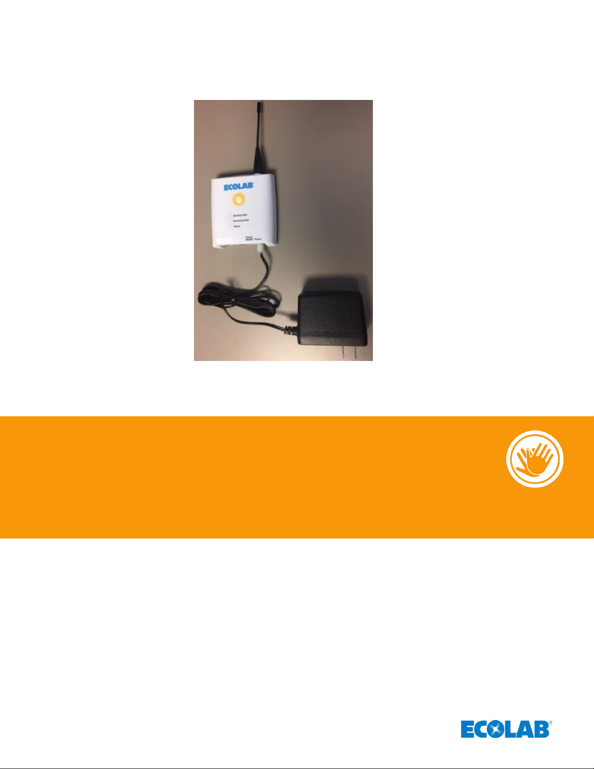
Ecolab® Hand Hygiene Program
Compliance Monitoring System
Hub Directions for Use
(92053067, HHCM915 HUB ASSY)
Page 2

1
Table of Contents
1. Introduction to the System ........................................................................................................................................................................... 2
1.1 The Wireless Network ............................................................................................................................................................................ 2
1.1.1 Hubs ..................................................................................................................................................................................................... 2
1.1.2 Gateway ............................................................................................................................................................................................. 2
1.2 The Dashboard Reporting Portal and Cloud Server ................................................................................................................. 2
2. Hub Kit Contents (Ecolab Part Number 92053067) ......................................................................................................................... 3
3. Hub Functionality ............................................................................................................................................................................................. 3
3.1 Address ........................................................................................................................................................................................................ 3
3.2 Heartbeat Signal ....................................................................................................................................................................................... 3
3.3 Hub Buffer Capacity ................................................................................................................................................................................ 3
4. Hub Components ............................................................................................................................................................................................ 4
5. Installation .......................................................................................................................................................................................................... 4
5.1 Power Requirements .............................................................................................................................................................................. 4
5.2 Mounting ...................................................................................................................................................................................................... 4
6. Hub Maintenance ............................................................................................................................................................................................ 4
7. Hub Troubleshooting ..................................................................................................................................................................................... 5
Appendix A – Certification and Safety Approvals ................................................................................................................................... 5
Page 3

2
Figure 1. Ecolab Hand Hygiene Program Compliance Monitoring System Components
1. Introduction to the System
1.1 The Wireless Network
A proprietary wireless network is used to transport event data collected by Dispenser Beacons and
Bed Beacons to the cloud for processing and archiving. The proprietary network composed to two types of
devices: Hub and the Gateway (or Condor).
1.1.1 Hubs
Hubs are installed throughout the healthcare facility and communicate with nearby Bed Beacons and
Dispenser Beacons. When an event is generated by either type of Beacon, it broadcasts the event
data to the nearest Hub. The Hub receives the event data and relays it either to the Gateway (Condor)
via RS485 or to the next nearest Hub. This process repeated, with event data being related from Hub to
Hub, until the data reaches the Hub that is connected to the Gateway (Condor).
1.1.2 Gateway
The Gateway (Condor) receives event data generated by Dispenser Beacons or Bed Beacons from
a directly attached (RS485) Hub, which acts as receiver for other Hubs nearby. The Gateway then
transmits the event data to a cloud server, via a secure cellular modem connection, for processing and
archiving.
1.2 The Dashboard Reporting Portal and Cloud Server
The Dashboard is a secure web-based application, which runs in the MicroSoft Azure cloud. The
Dashboard server is for collecting, processing and archiving onsite Dispenser Beacon and Bed Beacon
event data sent by the onsite Condor. The Dashboard provides a user-friendly interface, providing access
to your hospitals’ hand hygiene compliance data, statistics and reports compiled from event data.
Page 4

3
2. Hub Kit Contents (Ecolab Part Number 92053067)
1 – Hub
1 – Antenna
1 – Power Supply 24VDC 1A Wall Adapter
3. Hub Functionality
3.1 Address
Each Hub has a unique address, which is assigned during the manufacturing process. The Hub address is
transmitted along with the relayed event messages from devices. The Hub address label is located on the
back surface of the Hub (See Figure 2).
Figure 2. Hub Address Label
3.2 Heartbeat Signal
All Hubs generate a heartbeat signal every hour, if they do not receive any local device data. The heartbeat
is sent to the server to indicate that the Hub is functioning properly although no device data was generated
nearby. Missing heartbeats indicate that a Hub has gone off-line due to a possible power outage. The
Dashboard contains Hub meta data (location information), so that the off-line Hub can be easily located and
serviced.
3.3 Hub Buffer Capacity
Each Hub is capable of buffering (storing) up to 1000 events in case there is a temporary loss of
communications with the wider network (for example, the next nearest Hub has been unplugged or
removed), to minimize potential data loss.
Hub Address
Page 5

4
4. Hub Components
Figure 3. Hub Connectors, Components and Status Lights
• Antenna: Transmits and receives radio messages
• Power Connector: The 24VDC wall adapter powers the Hub and is connected here.
• 3 Status LED (Light Emitting Diode): Status (S) A solid Blue light indicates that the Hub is linked to
another Hub. Receiving (R): Red flashing light indicates that the Hub has received a radio transmission.
Transmitting (T) a Green flashing light indicates that the Hub has transmitted a radio message.
5. Installation
5.1 Power Requirements
Each Hub requires a 120VAC outlet. The wall adapter cord is approximately 6' in length and is typically
installed with a cord hider/conduit.
5.2 Mounting
A Hub weighs 3 oz. and can be mounted anywhere with two anchors, Velcro®, double sided tape or
CommandTM Strips.
6. Hub Maintenance
The Hub typically will not require cleaning. In the rare occurrence that it does need to be cleaned, the Hub may
be cleaned by wiping with a soft cloth. The cloth may be damp but must not be dripping wet. A
pre-moistened alcohol swab or any common hospital cleaner may also be used. Only the exterior of the Hub
may be cleaned. Do not attempt to clean any interior surface of the Hub as this can damage the circuitry. Do
not use abrasive cleaners or cleaning products in aerosol cans. The Hub
is splash resistant but not waterproof.
Page 6

5
7. Hub Troubleshooting
WARNING: Do not remove or relocate any Hub(s) in the Network without notifying your Ecolab
representative. Doing so could cause a disruption in data transmission and potentially
lost data.
• LED does not light
1. Verify that the Hub power supply is plugged into the powered outlet.
2. Use a volt meter to measure 120 volts at the power outlet.
3. Verify that the Hub power supply is properly seated.
4. Power cycle the Hub by unplugging the power supply, waiting 30 seconds and then plugging it back
in to the outlet.
5. If steps 1 – 4 are unsuccessful, an Ecolab service technician will need to replace the Hub.
• Dashboard Software Reports No Hub Heartbeats
1. Check that the LEDs light are on, to verify that the Hub is powered.
2. Verify that the antenna is connected.
3. Power cycle the Hub by unplugging the power supply, waiting 30 seconds and then plugging
it back in to the outlet.
4. Verify that there is no large test equipment near the Hub that could cause radio interference.
5. If steps 1 – 4 are unsuccessful, an Ecolab service technician will need to replace the Hub.
Appendix A – Certification and Safety Approvals
FCC Statement
NOTE: This equipment has been tested and found to comply with the limits for a Class B digital device, pursuant to Part 15
of the FCC Rules. These limits are designed to provide reasonable protection against harmful interference in a residential
installation. This equipment generates, uses, and can radiate radio frequency energy and, if not installed and used in
accordance with the instructions, may cause harmful interference to radio communications. However, there is no
guarantee that interference will not occur in a particular installation. If this equipment causes harmful interference to radio
or television reception, which can be determined by turning the equipment off and on, the user is encouraged to try and
correct the interference by one or more of the following measures:
• Reorient or relocate the receiving antenna.
• Increase the separation between the equipment and receiver
• Connect the equipment into an outlet on a circuit different from that to which the receiver is connected.
• Consult the dealer or an experienced radio/TV technician for help.
WARNING: Changes or modifications not expressly approved by Ecolab could void the user’s authority to operate the
equipment.
RF Exposure: This equipment complies with FCC radiation exposure limits set forth for an Uncontrolled environment. This
equipment should be installed and operated with minimum distance 20cm between the radiator and your body. This
transmitter must not be co-located or operating in conjunction with any other antenna or transmitter.
Industry Canada
Under Industry Canada regulations, this radio transmitter may only operate using an antenna of a type and maximum (or
lesser) gain approved for the transmitter by Industry Canada. To reduce potential radio interference to other users, the
antenna type and its gain should be so chosen that the equivalent isotropically radiated power (e.i.r.p.) is not more than
that necessary for successful communication.
Conformément à la réglementation d'Industrie Canada, le présent émetteur radio peut fonctionner avec une antenne d'un
type et d'un gain maximal (ou inférieur) approuvé pour l'émetteur par Industrie Canada. Dans le but de réduire les risques
de brouillage radioélectrique à l'intention des autres utilisateurs, il faut choisir le type d'antenne et son gain de sorte que la
Page 7

6
puissance isotrope rayonnée équivalente (p.i.r.e.) ne dépasse pas l'intensité nécessaire à l'établissement d'une
communication satisfaisante.
This device complies with Industry Canada license-exempt RSS standard(s). Operation is subject to the following two
conditions: (1) this device may not cause interference, and (2) this device must accept any interference, including
interference that may cause undesired operation of the device.
Le présent appareil est conforme aux CNR d'Industrie Canada applicables aux appareils radio exempts de licence.
L'exploitation est autorisée aux deux conditions suivantes: (1) l'appareil ne doit pas produire de brouillage, et (2)
l'utilisateur de l'appareil doit accepter tout brouillage radioélectrique subi, même si le brouillage est susceptible d'en
compromettre le fonctionnement.
This radio transmitter (IC: 10060A-92053067) has been approved by Industry Canada to operate with the antenna types
listed below with the maximum permissible gain and required antenna impedance for each antenna type indicated.
Antenna types not included in this list, having a gain greater than the maximum gain indicated for that type, are strictly
prohibited for use with this device.
Le présent émetteur radio (IC: 10060A-92053067) a été approuvé par Industrie Canada pour fonctionner avec les
types d'antenne énumérés ci-dessous et ayant un gain admissible maximal et l'impédance requise pour chaque type
d'antenne. Les types d'antenne non inclus dans cette liste, ou dont le gain est supérieur au gain maximal
indiqué, sont strictement interdits pour
l'exploitation de l'émetteur.
RF Exposure: This equipment complies with Industry Canada radiation exposure limits set forth for an Uncontrolled
environment. This equipment should be installed and operated with minimum distance 20cm between the radiator and
your body. This transmitter must not be co-located or operating in conjunction with any other antenna or transmitter.
Exposition aux radiofréquences : Cet équipement est conforme aux limites d’exposition par rayonnements définies par
l’industrie du Canada pour une utilisation dans un environnement non clos. Cet équipement doit être utilisé à une distance
minimale de 20 cm entre l’émetteur de radiation et votre corps. Cet émetteur ne doit pas être situe au même endroit qu’un
autre émetteur et ne doit pas être connecté à une antenne différente.
 Loading...