

Ecoflam MAX GAS 40 P, MAX GAS 70 P, MAX GAS 105 P, MAX GAS 120 P Operating Instructions Manual
Technical data
Dati tecnici
Données techniques
Datos técnicos
Технические характеристики
Operating instructions
Istruzioni per l’uso
Notice d’emploi
Manual de uso
Руководство по эксплуатации
Electric and hydraulic diagrams
Schemi elettrico e idraulico
Schémas électrique et hydraulique
Esquemas eléctrico e hidráulico
Электрические и гидравлические схемы
Spare parts list
Pièces de rechange
Parti ricambi
Запчасти
Piezas de recambio
GAS BURNERS
EN
IT
FR
ES
RU
MAX GAS 40 P
MAX GAS 70 P
MAX GAS 105 P
MAX GAS 120 P
MAX GAS 40 LN P TC 3142741
MAX GAS 40 LN P TL 3142742
MAX GAS 70 LN P TC 3142743
MAX GAS 70 LN P TL 3142744
MAX GAS 105 LN P TC 3142745
MAX GAS 105 LN P TL 3142746
MAX GAS 120 LN P TC 3142747
MAX GAS 120 LN P TL 3142748
www.ecoflam-burners.com

www.ecoflam-burners.com
420010372800
EN
IT
FR
ES
RU
2
Overview - Index of contents / Panoramica - Indice dei contenuti / Vue d'ensemble - Table des matières
Descripción - Sumario / Обзор - Содержание
Technical data
Dati tecnici
Données techniques
Datos técnicos
Технические характеристики
EN
IT
FR
ES
RU
3
Working fields
Campi di lavoro
Domaine de fonctionnement
Ámbito de funcionamiento
Рабочий диапазон
EN
IT
FR
ES
RU
4
Dimensions
Dimensioni
Dimensions
Dimensiones
Размеры
EN
IT
FR
ES
RU
5
Operating instructions for authorised specialists
EN 6 - 15
Istruzione per l’uso per il personale qualificato IT 16 - 25
Notice d’emploi pour l’installateur spécialiste FR
Instrucciones de montaje para el instalador especialista ES
Инструкция по эксплутации Предназначено для
квалифицированных специалистов по установке
RU
Pre-setting diagrams
Diagrammi di pre-taratura
Diagrammes de pré-configuration
Diagramas de la pre-configuración
диаграммы pre-установки
EN
IT
FR
ES
RU
26 - 28
Electric diagrams
Schemi elettrico
Schémas électrique
Esquemas eléctrico
Электрические схемы
EN
IT
FR
ES
RU
29
Spare parts list
Parti di ricambio
Pièces de rechange
Piezas de recambio
Запчасти
EN
IT
FR
ES
RU
30 - 33
3
www.ecoflam-burners.com
420010372800
EN
IT
FR
ES
RU
Technical data - Dati tecnici - Données techniques - Datos técnicos - Технические характеристики
MAX GAS 40 P MAX GAS 70 P MAX GAS 105 P MAX GAS 120 P
Burner output
min/max kW - kcal/h
Potenza bruciatore
min/max kW - kcal/h
Puissance du brûleur
min/max kW - kcal/h
Potencia del quemador
mín/máx kW - kcal/h
Мощность горелки
мин./макс., кВт - ккал/час
17 48 34 70
49
108
40
120
14.620 41.280
29.240
60.200
42.140 92.880
34.400
103.200
Operation
1 stage
Funzionamento
1 stadio
Fonctionnement
1 allure
Funcionamiento
1 etapa
Moдифиkaция
1 ступень
1
1 1 1
Regulating ratio Rapporto di regolazione
Rapport de régulation Relación de regulación
Коэффициент
регулирования
1:1
Fuel Combustibile
Fuel
Combustible
Топливо
Natural Gas (L.C.V. 8.570 kcal/Nm
3
), LPG (L.C.V. 22.260 kcal/Nm
3
)
(G20) Hu = 10,35 kWh/m
3
- (G25) Hu = 8,83 kWh/m
3
(G31) Hu = 25,89 kWh/m
3
Emission class Classe di emissione Classe d’émission
Tipo de emisión
Класс выделения
загрязняющих веществ
Standard Class 3 - GAS EN676 (<80mg/kWh)
Control box
Apparecchiatura di
controllo
Coffret de sécurité Cajetín de seguridad
Блок управления и
безопасности
E-BCU Ecoflam
Gas train Rampa gas Rampe gaz Rampa de gas Газовая рампа
GAS TRAIN TABLE - DIFFERENT MODELS / CONFIGUATIONS
Gas connection
Allacciamento gas
Raccordement gaz Conexión de gas Подсоединение газа
Rp1/2”
Rp1/2” Rp1/2” Rp1/2”
Gas input pressure Pressione di ingresso gas Pression d’entrée du gaz
Presión de entrada
del gas
Давление газа на входе 12-360 mbar (SEE GAS TRAIN MATCHING TABLE)
LPG input pressure
Pressione di ingresso
LPG
Pression d’entrée du gaz
propane
Presión de entrada
LPG
Давление LPG на входе
30-360 mbar (SEE GAS TRAIN MATCHING TABLE)
Air regulation
Air flap
Regolazione aria
Serranda dell'aria
Réglage de l’air
Volet d’air
Ajuste del aire
Válvula de aire
Настройка подачи
воздуха
Воздушная заслонка
-
- -
-
Flame monitor Rivelatore di fiamma Surveillance de flamme
Vigilancia de llama
Контроль пламени ionisation
ionisation
ionisation ionisation
Ignition transformer
Trasformatore
d'accensione
Allumeur Encendedor Устройство розжига
danfoss / cofi
danfoss / cofi danfoss / cofi danfoss / cofi
Electric motor
rpm - watt
Motore elettrico
giri motore - watt
Moteur
rpm - watt
Motor
rpm - watt
Электродвигатель
об/мин - watt
2800 rpm 2800 rpm 2800 rpm 2800 rpm
75 W
75 W
75 W 75 W
Voltage Tensione Tension
Tensión
Напряжение
230 V / 50-60 Hz
Power consumption
(operation)
Potenza elettrica
assorbita (Esercizio)
Puissance électrique
absorbée (en service)
Potencia eléctrica
absorbida (en
funcionamiento)
Потребляемая
электрическая
мощность: (при работе)
190 W
190 W 190 W 190 W
Weight
Peso
Poids
Peso Приблизительная масса 8,5 kg 9 kg 9,5 kg 9,5 kg
Protection level Classe di protezione
Indice de protection
Índice de protección
Класс электрозащиты
IP40
Sound pressure
level dB(A)
Livello pressione
sonora dB(A)
Niveau presion
acoustique dB(A)
Nivel de presion
acústico dB(A)
Уровень шума, dB(A) 60 65 65
71
Ambient temp. for
storage
Temperatura ambiente di
stoccaggio
Température ambiante de
stockage
Temperatura ambiente
de almacenamiento
температура хранения
-20°…+70° C
Temperature for use
Temperatura
d’utilizzazione
Température d’utilisation
Temperatura ambiente
de utilización
Рабочая температура
-10°…+60° C
Overview / Panoramica / Vue d'ensemble / Descripción / Обзор

4
www.ecoflam-burners.com
420010372800
EN
IT
FR
ES
RU
0
0,5
1
1,5
2
2,5
3
3,5
4
0 20 40 60 80 100 120
0 20 40 60 80 100
kW
kcal/h*1000
mbar
Working field
The working field shows burner
output as a function of
combustion chamber pressure.
It corresponds to the maximum
values specified by EN 267
measured at the test fire tube.
The efficiency rating of the
boiler should be taken into
account when selecting a
burner.
Calculation of burner output:
QF =
Q
N
η
K
QF = Burner output (kW)
QN = Rated boiler output (kW)
η
K
= Boiler efficiency (%)
Curva
Il campo di attività indica la
potenza del bruciatore in funzione
della pressione della camera di
combustione.
Corrisponde ai valori massimi
previsti dalla norma EN 267
misurati sul tubo della fiamma
di controllo.
In occasione della scelta del
bruciatore si deve tenere
conto del rendimento
energetico della caldaia.
Calcolo della potenza della
caldaia:
QF =
Q
N
η
K
QF= potenza della caldaia (kW)
QN= potenza nominale della
caldaia (kW)
η
K
= rendimento energetico
della caldaia (%)
Domaine de fonctionnement
Le domaine de fonctionnement
correspond aux valeurs mesurées
lors de l’homologation.
Elle correspond aux valeurs
max mesurées sur tunnel d’essai
d’après l’EN 267.
Pour le choix du brûleur, tenir
compte du rendement de la
chaudière.
Calcul de la puissance
calorifique:
QF =
Q
N
η
K
QF= Puissance calorifique (kW)
QN= Puissance nominale
chaudière (kW)
η
K
= Rendement chaudière (%)
Ámbito de funcionamiento
El ámbito de funcionamiento
corresponde a los valores
registrados en el momento
de la homologación.
Corresponde a los valores
máx medidos en el túnel de
ensayo según la EN 267.
Para la elección del quemador,
se ha de tener en cuenta el
rendimiento de la caldera.
Cálculo de la potencia
calorífica:
QF =
Q
N
η
K
QF = Potencia calorífica (kW)
QN = Potencia nominal
de la caldera (kW)
η
K
= Rendimiento de la
caldera (%)
Рабочий диапазон
Рабочий диапазон соответствует
значениям, измеренным при
сертификации.
Он соответствует максимальным
значениям, измеренным в
соответствии со стандартом
EN 267 в стандартном канале.
При выборе горелки
необходимо учитывать
КПД котла.
Расчет тепловой мощности:
QF =
Q
N
η
K
QF = Тепловая мощность, кВт
QN= Номинальная мощность
котла, кВт
η
K
= КПД котла, %
Overview - Working fields / Panoramica - Curve / Vue d'ensemble - Domaine de fonctionnement / Descripción - Ámbito de funcionamiento /
Обзор - Рабочий диапазон
MAX GAS 40
MAX GAS 120
MAX GAS 70
MAX GAS 105

5
www.ecoflam-burners.com
420010372800
EN
IT
FR
ES
RU
Overview - Dimensions / Panoramica - Dimensioni / Vue d'ensemble - Dimensions / Descripción - Dimensiones / Обзор - Размеры
X
Y
Z
Packaging
MAX GAS 40
GAS TRAIN DIMENSIONS:
refer to GT manual
Ø r
RrSr
d..°
Ø a
Ø b
Ø c
125
153
M
MAX GAS 70-105-120
d..°
Ø a
Ø b
Ø c
125
M
MAX GAS 40
CB
A
E
D-D1
F
G
M
126
151
I
L
Max Gas 70P-120P
NP
O
MAX GAS 70 - 105 - 120
A
BC
D-D1 E
M
125
I
L
G
F
N
O
Model
A
B C
D D1
E F G
I L M
N O P
MAX GAS 40 P 288 143
145 85 185
153 89 160
92/107
92/107 M8 54 73 -
MAX GAS 70 P 303 155
148 85 185
204 89 160
100/120
100/120 M8 52 71 82
MAX GAS 105 P 317 169
148 140 220
255 89 160
100/120
100/120 M8 52 71 82
MAX GAS 120 P 317 169
148 160 240
255 98 160
100/120
100/120 M8 52 71 82
Model Ø a Ø b
Ø c d°..
MAX GAS 40 P
100 130
150
45°
MAX GAS 70 P
110 140
170
45°
MAX GAS 105 P
110 140
170
45°
MAX GAS 120 P
110 140
170
45°
Model
X
Y
Z Kg
MAX GAS 40 P 415 400
310
8,5
MAX GAS 70 P 400 520
300
9
MAX GAS 105 P
400
520
300
9,5
MAX GAS 120 P
400
520
300
9,5

6
www.ecoflam-burners.com
EN
420010372800
Contents - Index - General warnings - Conformity declaration
Important notes
MAX GAS 40-120 P burners are designed
for the low-pollutant combustion of natural
gas and Liquefied Petroleum Gas.
The design and function of the burners
comply with standard EN676. Assembly
and commissioning must be carried out
only by authorised specialists and all
applicable guidelines and directives must
be observed.
Burner description
MAX GAS 40-120 P are single-stage,
fully automatic, monoblock type burners.
The special design of the burner head
provides low-polluting combustion with
high efficiency. In line with testing as
defined by EN676, the values comply
with emissions class 3 (NOx<80mg/kWh)
Emissions values may differ, depending on
combustion chamber dimensions,
combustion chamber load and the firing
system (three-pass boilers, boilers with
reverse firing).
They are suitable for use with all heat
generators complying with EN 303 or for
use with hot air generators complying with
DIN 4794, and DIN 30697 within their
respective performance range.
Use for any other application requires the
approval of Ecoflam.
The following standards should be
observed in order to ensure safe,
environmentally sound and
energy-efficient operation:
EN 676
Forced-draught gas burners
EN 226
Connection of fuel oil and forced-draught
gas burners to a heat generator.
EN 60335-1, -2-102
Specification for safety of household and
similar electrical appliances, particular
requirements for gas burning appliances.
Installation location
The burner must not be operated in rooms
containing aggressive vapours (e.g. spray,
perchloroethylene, hydrocarbon
tetrachloride, solvent, etc.) or tending to
heavy dust formation or high air humidity.
Adequate ventilation must be provided at
the place of installation of the furnace
system to ensure a reliable supply with
combustion air.
Variations may arise as a result of local
regulations.
We can accept no warranty liability
whatsoever for loss, damage or injury
caused by any of the following:
- Inappropriate use.
- Incorrect assembly or repair by the
customer or any third party, including the
fitting of non-original parts.
Provision of the system and the
operating instructions
The firing system manufacturer must
supply the operator of the system with
operating and maintenance instructions on
or before final delivery. These instructions
should be displayed in a prominent
location at the point of installation of the
heat generator, and should include the
address and telephone number of the
nearest customer service centre.
Notes for the operator
The system should be inspected by a
specialist at least once a year. It is
advisable to take out a maintenance
contract to guarantee regular servicing.
Declaration of conformity
for gas burners
We,
Ecoflam Bruciatori S.p.A.
declare under our sole responsibility
that the gas burners named
MAX GAS
conform to the following standards:
EN 676: 2008
EN 60335-1: 2008
EN 60335-2-30: 2006
EN 60335-2-102: 2007
EN 55014-1: 2008 + A1: 2009
EN 55014-2: 1998 + A1: 2001 + A2:
2008
These products bear the CE mark in
accordance with the stipulations of the
following directives:
2009/142/EEC Gas Appliance Directive
2006/95/EEC Low Voltage Directive
2004/108/EEC EMC Directive
2006/42/EC Machinery directive
Resana, 28
th
June 2011
M. PANIZZON
Ecoflam burners have been designed and built in compliance with all current regulations
and directives.
All burners comply to the safety and energy saving operation regulations within the standard
of their respective performance range. The quality is guaranteed by a quality and management
system certified in accordance with ISO 9001:2008.
Overview Technical data 3
Working fields 4
Dimensions 5
Contents Index 6
General warnings 6
Conformity declaration 6
Burner description 7
Function General safety functions 8
E-BCU GAS control and safety unit 9
Installation Burner assembly 10
Electrical connection 11
Checks before commissioning 11
Start up Adjusting burner output 12
Air pressure switch adjustment - setting gas pressostat 13
Service Maintenance 14
Troubleshooting 15
Overview Pre-setting diagrams 26-28
Electrical diagrams 29
Spare parts list 30-33

7
www.ecoflam-burners.com
EN
420010372800
A1 E-BCU Gas control unit
F6 Air pressure switch
M1 Electric motor
T1 Ignition transformer
Y Graduated rod for head adjustment
3 Air regulation in the burner head
5 Housing
8 Blast tube
10 Wieland socket
14 Burner hood
15 Burner flange
16 Reset key
17 Measuring point for gas pressure
103B Air regulation
113 Air intake
15
14
MAX GAS 40 LN P TC - 230V/50-60Hz
MAX GAS Gas
RANGE NAME BY FUEL TYPE
MAX 40 40 kW
MODEL SIZE (Gas: kW; Oil: kg/h)
LN Low NOx Class 3 GAS EN676 (<80 mg/kWh)
- Standard Class 2-GAS EN676 (<120 mg/kWh)
EMISSION COMBUSTION TYPE
P 1 stage
OPERATION TYPE
TC Short head
TL Long head
HEAD TYPE
MET Natural gas
LPG LPG
FUEL
230V/50-60Hz 230 Volt, 50-60 Hz
ELECTRICAL SUPPLY TO THE SYSTEM
Scope of delivery
The burner is delivered in a modular system of
packagings i.e. separate set/box:
BBCH: Burner Body with Combustion Head
with flange.
- 1 bag including :- multilanguage technical manual.
- wieland plug.
- spanner.
- screws, nuts and washer.
GT: separate Gas Train
KIT & ACS are managed and delivered separately
Contents - Burner description
A1
8
113
10
5
3
103B
Y
M1
F6
16
KIT & ACS delivered separately
17

8
www.ecoflam-burners.com
EN
420010372800
Function - General safety functions
Description of functions
When the system is switched on for the
first time, after a power failure or safety
shutdown, after a lack of gas or after the
system has been out of operation for 24
hours, the pre-ventilation period of 24
seconds begins.
During pre-purge period:
- blower pressure is monitored
- the combustion chamber is monitored for
flame signals.
At the end of the pre-purge period:
- ignition is switched on.
- main and safety valve are opened.
- burner starts.
Monitoring
The flame is monitored by an ionisation
probe. The probe is insulated and
fitted to the gas head and is routed
through the flame disc into the flame
zone. The probe must not have any
electrical contact with earthed parts. The
burner switches to lock-out if a short
circuit occurs between the probe and
the burner earth.
During burner operation, an ionised
zone is produced in the gas flame
through which a rectified current flows
from the probe to the burner head. The
ionisation current must be at least 1,5 µA.
Safety functions
- If no flame is produced when the burner
is started (gas release), the burner will be
switched off at the end of the safety
period, lasting no more than 3 seconds,
and the gas valve will close.
- If the flame goes out during operation,
the gas supply is interrupted within one
second. A restart takes place. Once the
burner starts, operation is continued.
Otherwise, a safety lock-out occours.
- If there is a lack of air during reventilation
or operation, a safety lock-out occours.
- If there is a lack of gas, the burner does
not begin operation or switches off.
A waiting time of 2 minutes follows. This is
followed by a further start attempt. If there
is still no gas pressure, a further waiting
time of 2 minutes follows. The waiting time
can only be reset by interrupting the
power supply to the burner.
Waiting times: 3 x 2 min, then 1 hour.
In the event of controller shutdown
- Controller thermostat interrupts heat
request.
- Gas solenoid valves close.
- Flame goes out.
- Burner motor switches off.
- Burner is ready for operation.
1108106
119
Y12104 F4119.1119 pBr Y13
119.2
F6
F4 Minimum gas pressure switch
F6 Air pressure switch
Y13 Main solenoid valve
Y12 Safety solenoid valve
1 Thermally-triggered safety shut-off valve (installation resident)
104 Gas pressure regulator
106 Filter
108 Gas ball valve (installation resident)
119pBr Measuring point for gas outlet pressure
119.1 Measuring point for gas pressure in valve space
119.2 Air pressure measuring point

9
www.ecoflam-burners.com
EN
420010372800
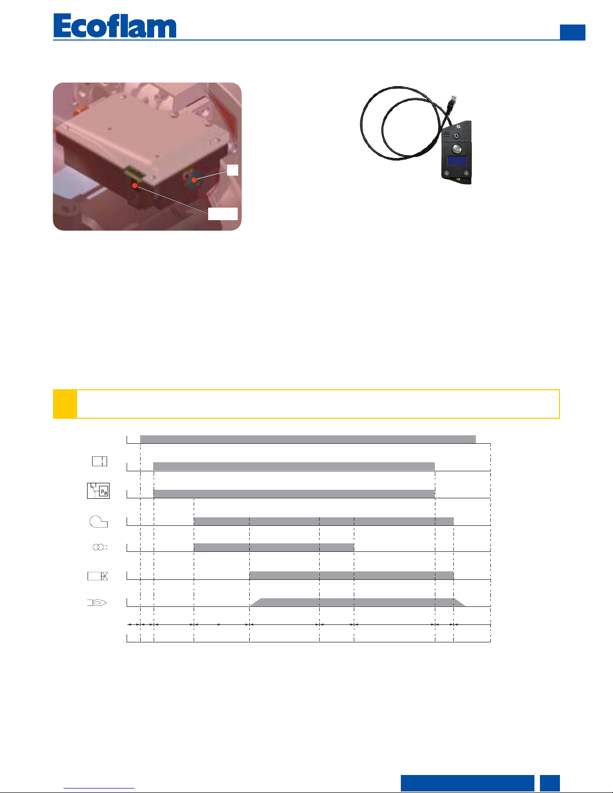
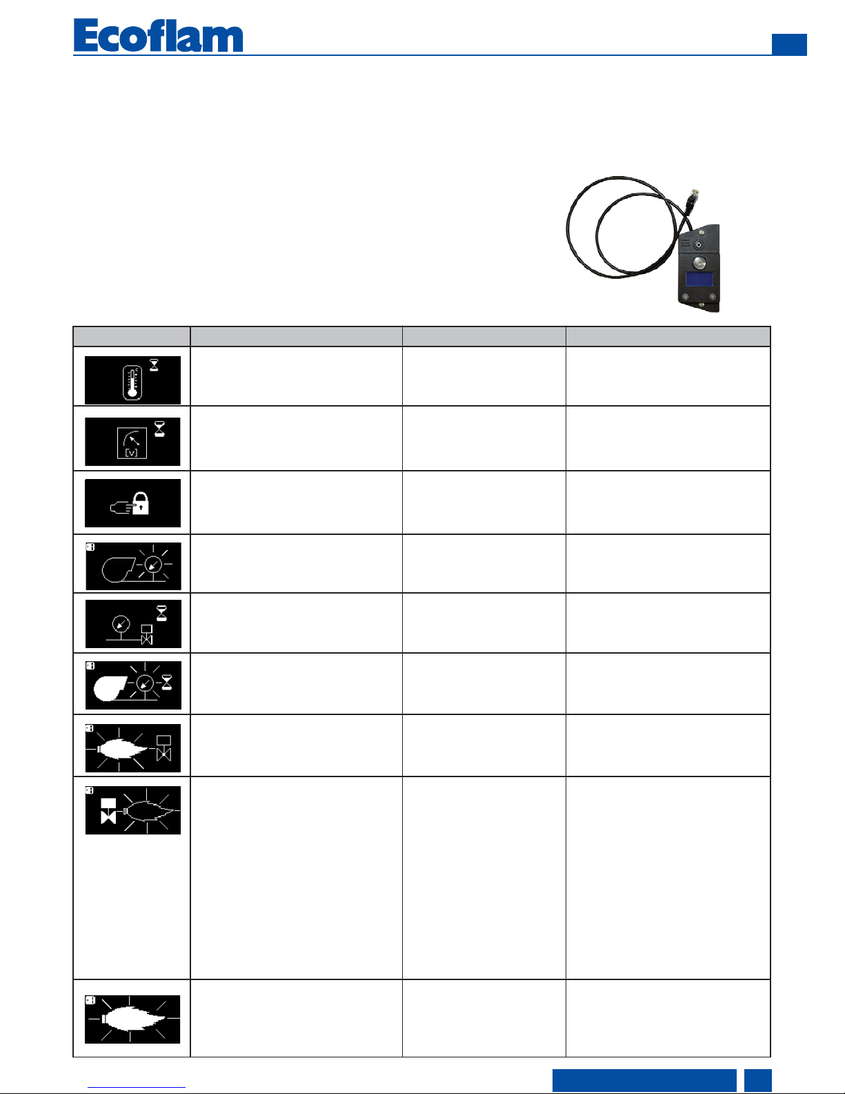
The E-BCU GAS fuel gas/LPG control and safety unit controls and monitors the forced draught burner. The microprocessor-controlled
program sequence ensures maximum stability of time periods, regardless of fluctuations in the power supply or ambient temperature.
The design of the automatic combustion control unit protects it from the effects of brownouts. Whenever the supply voltage drops
below its rated minimum level (170 V), the control unit shuts down - even in the absence of a malfunction signal. The control unit
switches itself back on again once the voltage has exceeded the 178 V.
Locking and unlocking the system
The control unit can be locked (switched to malfunction) and unlocked (malfunction cleared) by pressing the R reset button, provided
the system is connected to the mains power supply.
R
RJ45
R- Reset button + lock-out led.
RJ45 - Connector for PC interface (diagnostic, separate item).
LINE Electrical supply
BV... Fuel valve
FS Flame signal
M Burner motor
OW Release contact of oil preheater
W Control thermostat or pressurestat
Z Ignition transformer
1 No voltage
2 Power supply on, no heat request
3 Heat request: pre-heater ON
4 Preventilation: motor ON, ignition ON
4’ Parasitic flame monitoring
5 Burner start: solenoid valve OFF, flame
production, safety time
6 Flame present, post-ignition period
7 Burner operation
8 End of heat request, solenoid valve
closes, burner stop
9 Standby
!
Always disconnect the power supply before installing or removing the control unit
Do not attempt to open or carry out repairs on the control unit
Function - E-BCU GAS control and safety unit
KIT E-BCU
DIAGNOSTIC TOOL
(not supplied)
W
LP
M
Z
BV1
FS
LINE
1
< 400s 33s 3s
25s
5s --- -< 1s
23 44’ 5 6 7 8 9

10
www.ecoflam-burners.com
EN
420010372800
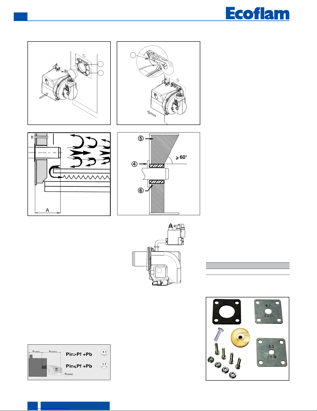
Installation
- Burner assembly
Burner blast tube insertion depth and
brickwork
Unless otherwise specified by the boiler
manufacturer, heat generators without a
cooled front wall require brickwork or
insulation 5 as shown in the illustration.
The brickwork must not protrude beyond
the leading edge of the blast tube, and
should have a minimum conical angle of
60°. Gap 6 must be filled with an elastic,
non-combustible insulation material. For
boilers with reverse firing, the minimum
burner tube insertion depth A as speci
fied
in the boiler manufacturer’s instructions
must be observed.
Exhaust system
To avoid unfavourable noise emissions,
right-angled connectors should not be
used on the flue gas side of the boiler.
Burner assembly
The burner is fixed by mean of connecting
flange and therefore to the boiler.
Installation:
• fix the flange 3
to the boiler with
the screws
4
• turn the burner slightly, guide it into
the flange and secure using screw
5
Removal:
• loosen screw
5
• turn the burner out and pull it out of
the flange
General regulations applying to the
gas connection
• The gas train must only be connected
to the gas mains by a recognised
specialist.
• The cross-section of the gas line should
be of a size designed to guarantee that the
gas flow pressure does not drop below the
specified level.
• A manual shut-off valve (not supplied)
must be fi tted upstream of the gas train.
Gas lines
When installing the gas lines and gas train,
the general EN676 directives and
guidelines must be observed.
EN676 compulsory kit and accessories in
order to comply to the safety regulations.
Additional accessories and kits shall be
installed by the installer in accordance to
the local safety regulations and codes of
practise.
LEGENDA
Pf: Back pressure of furnace
Pb: Pressure of burner (combustion head
+ complete gas train)
Pin: Minimum inlet pressure
For operation with Lique fied Petroleum
Gas, it is necessary to order the kit and
follow the instructions given in the
specific manual.
LPG TRANSFORMATION
KITLPG-MAXGAS...
–
+
2
3
5
1
3
4
LPG

11
www.ecoflam-burners.com
EN
420010372800
Installation
- Electrical connection - Checks before commissioning
Electrical connection
The electrical installation and connection
work must only be carried out by an
authorised electrical specialist.
All applicable rules and regulations must
be observed.
The electrical installation should include a
type A circuit breaker.
The applicable guidelines and
directives must be observed, as well as
the electrical circuit diagram supplied
with the burner!
• Check to ensure that the power supply
voltage is as specified in the electric
diagram and in data plate.
• Burner fuse: 5 A.
Electrical connection (plug-in)
It must be possible to disconnect the
burner from the mains using an
omnipolar shutdown device complying
with the standards in force. The burner
and heat generator (boiler) are connected
by a 7-pin connector (fig.1).
Connecting the gas train
Connect the gas train to the plugs on the
burner.
Checks before commissioning
The following must be checked before
initial commissioning:
• That the burner is assembled in
accordance with the instructions given
here.
• That the burner is pre-set in accordance
with the values in the adjustment table.
• Setting the combustion components.
• The heat generator must be ready for
operation, and the operating regulations
for the heat generator must be observed.
• All electrical connections must be correct.
• The heat generator and heating system
must be filled with water and the
circulating pumps must be in operation.
• The thermostats, pressure regulator, low
water detectors and any other safety or
limiting devices that might be fitted must
be connected and operational.
• The exhaust gas duct must be
unobstructed and the secondary air
system, if available, must be operational.
• An adequate supply of fresh air must be
guaranteed.
• The heat request must be available.
• Sufficient gas pressure must be
available.
• The fuel supply lines must be assembled
correctly, checked for leaks and bled.
• A standard-compliant measuring point
must be available, the exhaust gas duct up
to the measuring point must be free of
leaks to prevent anomalies in the
measurement results.
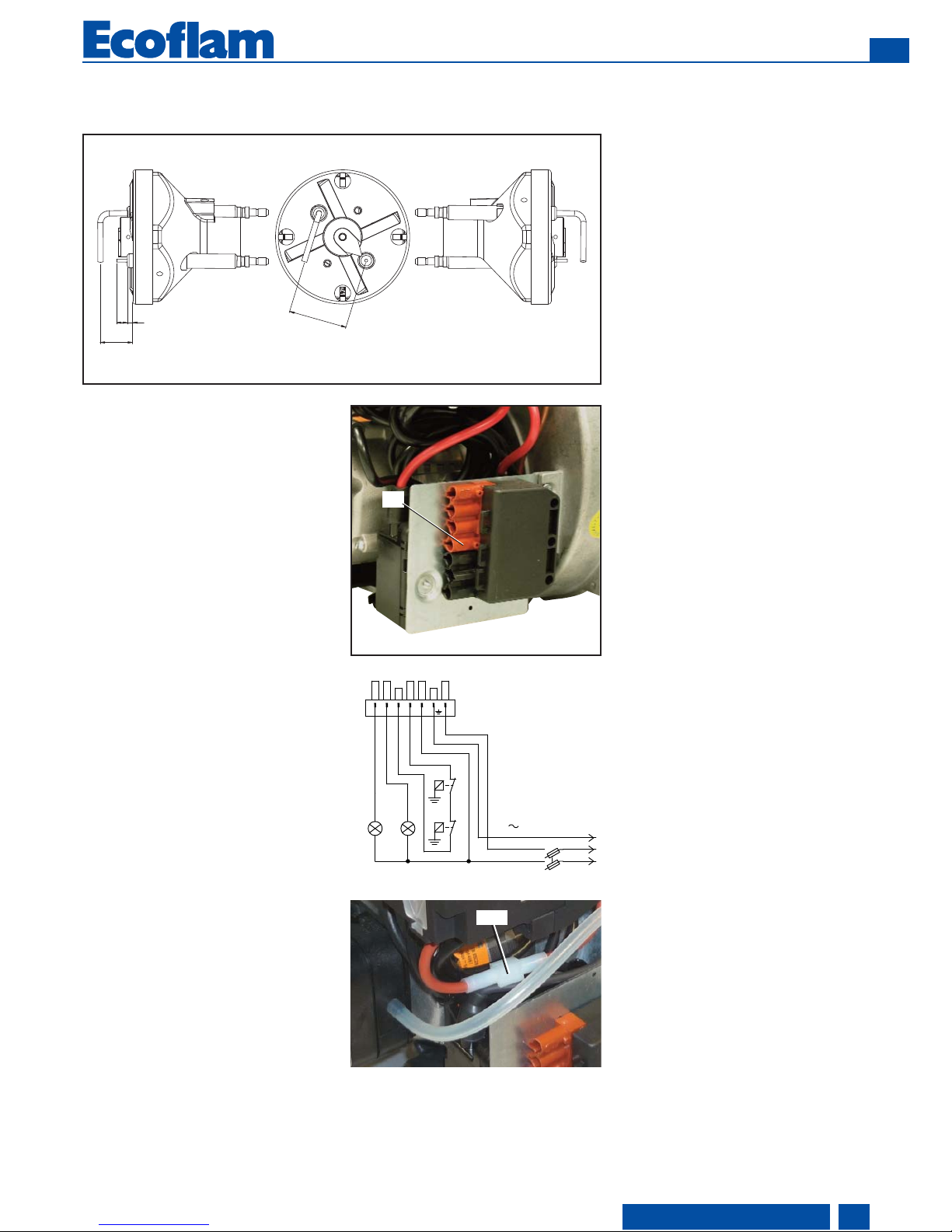
1
Position of electrodes
Setting the ionisation probe and
ignition electrode: see diagram
Always check the position of the
electrodes after service or substitution
or assembly of LPG kit as wrong position
might cause ignition problem.
Ionisation current measurement
To measure the ionisation current,
disconnect connector B10 and connect
a multimeter with a measuring range of
0-100 µA.
The ionisation current must be at least 1,5
µA.It is also possible to read the ionisation
current on the display of the E-BCU
diagnostic tool.
18
36
30
B10
S3B4 T2 NT1 L1
T
P
STC
PE
N
L
Q
HLF HLB
T
P
STS
Input Voltage

1,0
1,5
2,0
2,5
3,0
3,5
4,0
MAX GAS 70 P NATURAL GAS
-1,5
-1,0
-0,5
0,0
0,5
080706050403
2
3
1
4,5
0
5
5,2
5,5
6
6,3
6,5
6,8
7,0
7,3
7,5
0
1
1,5
2
5
7
2,5
3
9
12
12
www.ecoflam-burners.com
EN
420010372800
+
-
A
Start up
- Adjusting burner output
Pre-setting diagrams in appendix
Before start-up adjust the burner
parameters according to the settings given
in the diagrams for GAS/LPG.
These values have been determined in
our test labs and are useful for the first
switch-on as final setting must be done
using a combustion analyzer.
How to read and adjust the values:
- determine the output required
- determine the combustion chamber back-
pressure
- read the position of the head in the
diagram and adjust it according
- read the position of the air flap and adjust
it according
Optimising combustion values
The factory setting shall be modified
according to the output requeired.
The diagrams of air/head setting
that are available in the appendix
of this manual are a guide for ensuring
that the burner functions as well as
possible.
!
Risk of air blast!
Continuously check CO, CO2and soot emissions when adjusting the output of
the burner. Optimise combustion values in the event of CO formation. CO must
not exceed 50 ppm.
Air damper setting (A).
To act on the screw in figure:
• to increase output,
turn screwdriver clockwise
• to reduce output,
turn screwdriver counterclockwise
N.B. observe the minimum required
flue gas temperature specified by the
boiler manufacturer and the requirements
demanded of ue gas ducts for avoiding
condensation.
Adjustment of gas solenoid valve
Refer to the gas train manual for the gas
setting of the gas train selected.
+-+
-
B
Firing head setting (B).
To act on the screw in fi gure:
• turn Allen key till you reach the
requested value (index 0-4,5).
+
-
A
+-+
-
B
MAX GAS 40 P
MAX GAS 70-120 P
MAX GAS 40 P
MAX GAS 70-120 P
pressure in the combustion chamber (mbar)
output (kW)
head gas pressure (on elbow) (mbar)
head position
air damper position

13
www.ecoflam-burners.com
EN
420010372800
Start up
- Air pressure switch adjustment - Setting gas pressostat
Operating check
Flame monitoring must be checked for
safety as part of initial commissioning and
also after servicing or if the system has
been out of operation for any significant
period of time.
- Start attempt with gas ball valve closed:
the automatic combustion control unit must
switch to gas shortage or malfunction after
the end of the safety period.
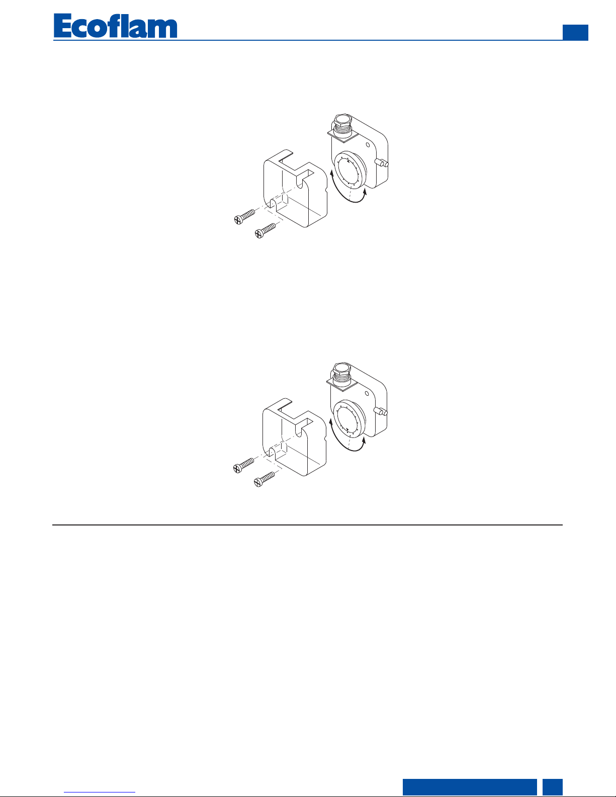
Air pressure switch calibration
The air pressure switch is provided for
monitoring the pressure of the
combustion air fan.
Unscrew screws A and B and remove
cover C.
After the air and gas setting you have to
calibrate the air switch with the burner
working on the low flame by slowly turning
the relative knob clockwise until the burner
locks out. Read the value and then
decrease it by 15%.
WARNING: the air pressure switch shall
prevent the air pressure to go below 85%
from the adjustment value in order to
prevent the CO in the fumes to exceed 1%
(10000 ppm).
Min gas pressure switch
The gas pressure switch has the function
to check that the gas pressure before the
gas valve does have the minimum
pressure to make the burner running
correctly.
Unscrew off and remove cover M. - Set
knob N to a value equal to 60% of gas
nominal feed pressure (i.e. for natural gas
nom. pressure = 20 mbar, set knob to a
value of 12 mbar; for LPG nom. pressure
of G30/G31- 30/37 mbar, set knob to a
value of 18 mbar). Screw up cover M.
0,4
0,6
0,9
3,0
1,5
2,1
1,8
2,4
2,7
1,2
A
B
C
D
2
,
5
5
10
15
5
0
2
5
3
5
30
40
45
2
0
I
L
M
N

14
www.ecoflam-burners.com
EN
420010372800
Service - Maintenance
+
–
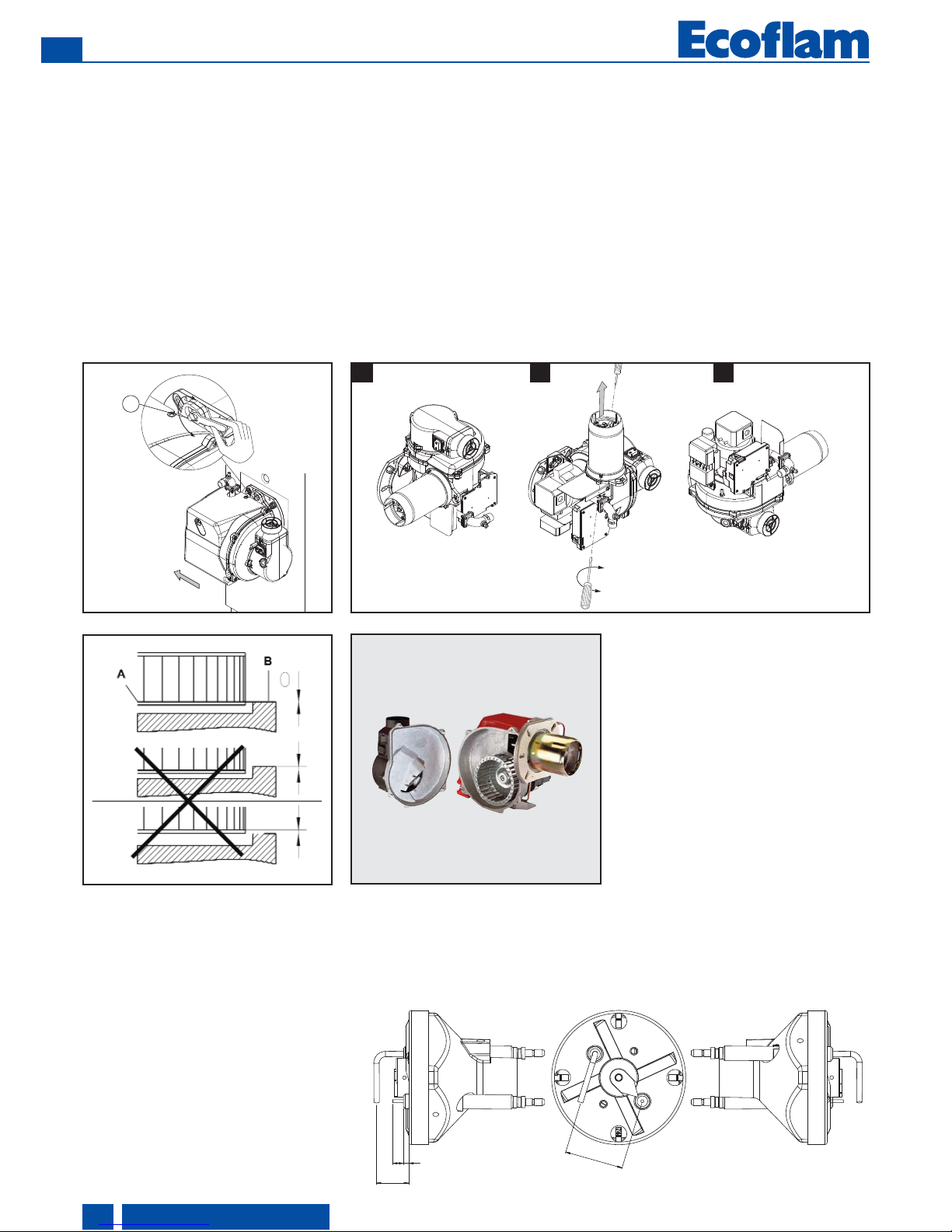
Fan assembly
Observe the positioning diagram above
when replacing the motor and blower
wheel. The inside flange A of the blower
wheel must be fitted at the same level as
the equipment plate B. Insert a straight
edge between the wing of the blower wheel
and set A and B to the same height, tighten
the set screw on the blower wheel
(maintenance position 1).
Burner and boiler servicing must only
be carried out by qualified personell.
The system operator is advised to take
out a service contract to guarantee
regular servicing.
Attention
• Disconnect the electrical supply before
carrying out any maintenance or
cleaning work.
• The blast tube and firing head may be
hot.
Checking the exhaust gas temperature
• Check the flue gas temperature at
regular intervals.
• Clean the boiler if the flue gas
temperature is more than 30°C above
the value measured at the time of
commissioning.
• To simplify the check, use a flue gas
temperature indicator.
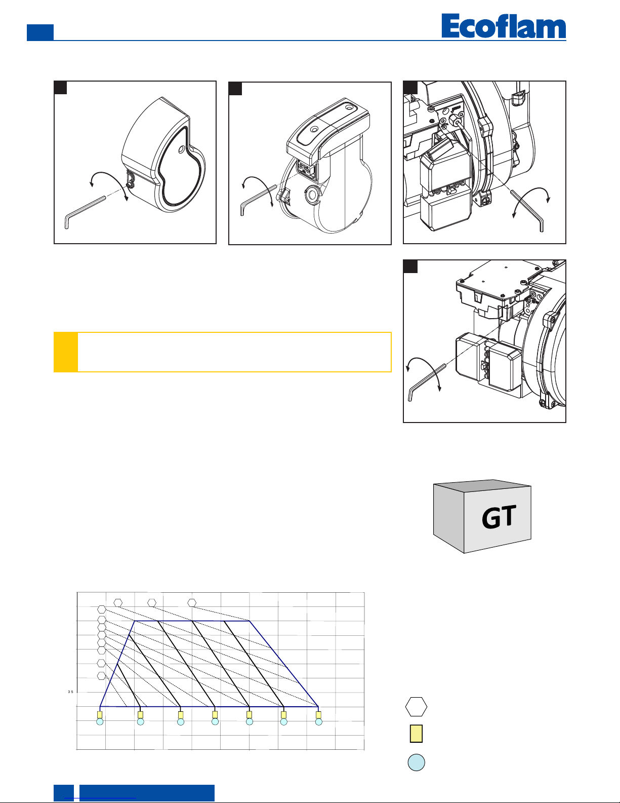
Burner maintenance positions
• After removing the screws 5 turn the
burner and pull it out of the flange. It is
possible to fix the burner in three positions
for maintenance.
Position 1
Maintenance line air
(cleaning/substitution fan)
Position 2
Burner head maintenance.
Position 3
Maintenance components.
Maintenance on the burner
• Check gas supply components (tubes,
lines) and their connections for leaks
or signs of wear, replace if necessary.
• Check electrical connections and
connection cables for damage,
replace if necessary.
• Check gas filter, clean or replace as
necessary.
• Clean fan wheel and housing and
check for damage.
• Check and clean the mixing unit.
• Check ignition electrodes block,
readjust or replace as necessary.
• Start burner, check flue gas data,
correct burner settings if necessary.
• Check the setting for air pressure
switch and gas pressostat.
• Check the gas train settings.
• Carry out an operating check.
1 2 3
–
+
2
3
5
18
36
30

15
www.ecoflam-burners.com
EN
420010372800
Fault diagnosis and repair
In the event of a malfunction, first check
that the prerequisites for correct
operation are fu llfilled:
1. Is the system connected to the
power supply?
2. Is there any gas pressure?
3. Is the gas shut-off valve open?
4. Are all control and safety devices,
such as the boiler thermostat, low
water level detector, limit switch,
etc. adjusted correctly?
If the malfunction persists, use the
following table.
It is not permitted to repair any
components relevant to safety. These
components must be replaced by parts
with the same order number.
Only use original spare parts.
NB: after each operation:
• under normal operating conditions
(doors closed, hood fitted, etc.), check
combustion and check the individual
lines for leaks.
• Record the results in the relevant
documents.
E-BCU diagnostic tool must be used to
read the faults by service personell.
Service - Troubleshooting
Fault Symbol fault Cause Remedy
No heat request
Thermostats defective or
incorrectly adjusted
Adjust the thermostats, replace if
necessary.
Burner does not start after
thermostat shutdown
No malfunction indicated on the
automatic combustion control unit
Drop in supply voltage or
power failure.
Control unit malfunction
Check the cause of the fall in voltage or the
power failure
Replace the control unit.
Burner starts briefl y when switched on,
switches off and the red LED lights up
Control unit was
deliberately shut down
Unlock the unit
Burner does not start
Air pressure switch: not in rest position
Incorrect adjustment
Contact is welded
Readjust the pressure switch
Replace the pressure switch
Burner does not start
Low gas pressure
Insufficient gas pressure
Gas pressostat wrongly set or defective
Check gas lines
Clean the filter
Check the gas pressostat or replace the
compact gas unit
Burner blower starts up
Burner does not start
Air pressure switch: the contact does
not close
Check the pressure transmitter (foreign
bodies) and wiring
Burner blower starts up
Burner does not start
Flaring during pre-ventilation or preignition
Check the valve
Check fl ame monitoring
The burner starts, the ignition
switches on, then failure
No flame at the end of the safety period
Gas throughput set incorrectly
Faulty fl ame monitoring circuit
No ignition arc
Electrode(s) short-circuited
Ignition cable damaged or defective
Ignition transformer defective
Automatic combustion control unit
Solenoid valves do not open
Valves jamming
Adjust the gas throughput
Check the condition and position of the
ionisation sensor in relation to earth
Check the condition and connections of the
ionisation ci rcuit (cable(s) and
measurement bridges)
Adjust, clean or replace electrode(s)
Connect or replace the cable(s)
Replace the transformer
Replace the control unit
Check the cabling between the control
unit and external components
Replace the compact gas unit
Replace the valves
Flame extinguishing
during operation
Air pressure switch: contact opens
during startup or during operation
Flame failure during operation
Adjust or replace the pressure switch
Check the ionisation sensor circuit
Check or replace the automatic
combustion control unit

16
www.ecoflam-burners.com
IT
420010372800
Contenuti generali - Indice - Avvertenze generali - Dichiarazione di conformità
Avvertenze importanti
I bruciatori MAX GAS 40-120 P sono
progettati per la combustione di gas
naturale e di gas propano, con basse
emissioni inquinanti. I bruciatori sono
conformi alla norma EN 676, dal punto di
vista della progettazione e del
funzionamento. Montaggio, messa in
funzione e manutenzione devono essere
eseguiti esclusivamente da personale
tecnico autorizzato, nel rispetto delle
direttive e delle prescrizioni in vigore.
Descrizione del bruciatore
I bruciatori MAX GAS 40-120 P sono
monostadio, a funzionamento completamente automatico in esecuzione monoblocco. La costruzione speciale della testa
di combustione permette di ottenere una
combustione con un debole tasso di ossidi
di azoto e un coefficiente di rendimento
elevato. I valori delle emissioni
corrispondono alla classe 3, come definita
da EN676 (NOx<80mg/kWh).
A seconda della geometria del focolare,
della carica e del sistema di combustione
(caldaia a tre percorsi, caldaia a
combustione inversa), si possono
riscontrare valori di emissione diversi.
Sono adatti per l'allestimento di tutti i
generatori di calore conformi alla norma
EN 303 o degli aerotermi secondo DIN
4794 o DIN 30697 nell'ambito del rispettivo
range di potenza. Per ogni altro utilizzo e
necessaria l'autorizzazione della Ecoflam.
Al fine di garantire un funzionamento
sicuro, non inquinante ed a basso
consumo energetico, è necessario
rispettare le seguenti norme:
EN 676
Forced-draught gas burners
EN 226
Allacciamento di bruciatori di gasolio a
nebulizzazione e bruciatori di gas ad
aria soffiata su generatori di calore
EN 60335-1, -2-102
Sicurezza degli apparecchi elettrici per uso
domestico, norme particolari per gli
apparecchi con combustione a gas.
Luogo di installazione
Il bruciatore non dev'essere messo in
funzione in locali in cui siano presenti
vapori aggressivi (ad es. lacca per capelli,
percloroetilene, tetracloruro di carbonio),
notevole accumulo di polvere o forte
umidità dell'aria (ad es. lavanderie).
Una adeguata ventilazione deve essere
fornita nel locale dell’installazione in modo
da garantire le condizioni per una buona
combustione.
Si possono riscontrare scostamenti
dovuti ad eventuali normative locali.
Si esclude qualsivoglia responsabilità
per eventuali danni derivanti dalle
seguenti cause:
- utilizzo non conforme.
- montaggio difettoso e/o riparazione a
cura dell'acquirente o terzi, ivi inclusa
l'applicazione di elementi di origine
estranea.
Consegna e istruzioni per l'uso
Il costruttore dell'impianto di combustione
è tenuto a consegnare al gestore
dell'impianto, al più tardi all'atto della
consegna dello stesso, le istruzioni per
l'uso e la manutenzione. Queste istruzioni
devono essere appese nel locale di
installazione del generatore termico in
modo ben visibile. Devono essere indicati
l'indirizzo ed il numero telefonico del punto
di assistenza più vicino.
Avvertenza per il gestore
L'impianto dev'essere controllato almeno
una volta l'anno da un tecnico specializzato. Al fine di garantire un'esecuzione
regolare, si suggerisce di stipulare un
contratto per la manutenzione
dell'impianto.
Dichiarazione di conformità
per bruciatori a gas
We,
Ecoflam Bruciatori S.p.A.
dichiariamo sotto la nostra
responsabilità, che i bruciatori a gas
MAX GAS
sono conformi alle norme elencate :
EN 676: 2008
EN 60335-1: 2008
EN 60335-2-30: 2006
EN 60335-2-102: 2007
EN 55014-1: 2008 + A1: 2009
EN 55014-2: 1998 + A1: 2001 + A2:
2008
Questi prodotti vengono contrassegnati
con il marchio CE nel rispetto delle
direttive:
2009/142/EEC Gas Appliance Directive
2006/95/EEC Low Voltage Directive
2004/108/EEC EMC Directive
2006/42/EC Machinery directive
Resana, 28
th
June 2011
M. PANIZZON
I bruciatori Ecoflam sono stati progettati e costruiti nel rispetto delle normative e direttive correnti.
Tutti i bruciatori rispondono alle normative sulla sicurezza e sul risparmio energetico nel limite del
campo di lavoro dichiarato.
La qualità del prodotto è garantita dal sistema di certificazione in base alla norma ISO 9001:2008.
Panoramica Dati tecnici 3
Curve di lavoro 4
Dimensioni d’ingombro 5
Contenuti generali Indice 16
Avvertenze generali 16
Dichiarazione di conformità 16
Descrizione del bruciatore 17
Funzione Funzioni generali di sicurezza 18
Programmatore di comando e sicurezza E-BCU GAS 19
Installazione Montaggio del bruciatore 20
Connessione elettrica 21
Controlli da eseguire prima della messa in funzione 21
Messa in funzione Regolazione del bruciatore 22
Regolazione dei pressostati aria e gas 23
Assistenza Manutenzione 24
Possibili inconvenienti 25
Panoramica Diagramma di pre-taratura 26-28
Schemi elettrici 29
Parti di ricambio 30-33

17
www.ecoflam-burners.com
IT
420010372800
A1 E_BCU GAS programmatore di comando
e sicurezza gas
F6 Pressostato aria
M1 Motore elettrico
T1 Trasformatore d'accensione
Y Asta graduata per regolazione testa
3 Regolazione dell'aria nella testa di
combustione
5 Fusione
8 Boccaglio
10 Presa Wieland
14 Cofano bruciatore
15 Flangia bruciatore
16 Pulsante Reset
17 Punto di misurazione della pressione del
gas
103B Regolazione dell’aria
113 Cuffia aria
MAX GAS 40 LN P TC - 230V/50-60Hz
MAX GAS Gas
NOME
MAX 40 40 kW
MODELLO (Gas: kW; Gasolio: kg/h)
LN Low NOx Classe 3 GAS EN676 (<80 mg/kWh)
- Standard Classe 2-GAS EN676 (<120 mg/kWh)
EMISSIONI
P 1 stadio
TIPO DI FUNZIONAMENTO
TC Testa corta
TL Testa lunga
TIPO TESTA
MET Gas Naturale
LPG Gas Propano
COMBUSTIBILE
230V/50-60Hz 230 Volt, 50-60 Hz
TENSIONE DI ALIMENTAZIONE
Contenuti generali - Descrizione del bruciatore
A1
8
113
10
5
3
103B
Y
M1
F6
16
Imballaggio
Il bruciatore è consegnato con un sistema modulare di
imballo (scatole separate) i.e. separate set/box:
BBCH: Brucitore completo con testa di combustione e
flangia.
- 1 sacchetto : - manuale tecnico in multilingue.
- spina wieland.
- chiave esagonale.
- viti, dadi e rosette.
GT: Rampa Gas separata
KIT & ACS ordinabili e consegnati separatamente
KIT & ACS ordinabili e
consegnati separatamente
15
14
17

18
www.ecoflam-burners.com
IT
420010372800
Funzione - Funzioni generali di sicurezza
Descrizione del funzionamento
Alla prima messa sotto tensione, dopo
un'interruzione di corrente e una fase di
messa in sicurezza, dopo un'interruzione
di gas o dopo un arresto di 24 ore,
comincia un tempo di preventilazione di
24 sec.
Durante il tempo di preventilazione:
- la pressione dell'aria viene monitorata.
- controllo della presenza di eventuali
segnali di fiamma anomali.
Al termine del tempo di preventilazione
- l'accensione eP inserita.
- l'elettrovalvola principale e di sicurezza eP
aperta.
- il bruciatore si avvia.
Sorveglianza
La fiamma viene monitorata da una sonda
di ionizzazione. La sonda eP montata in
modo isolato sulla testa del gas ed eP
diretta attraverso il disco fiamma nella
zona della fiamma. La sonda non deve
avere alcun contatto elettrico con
componenti messi a terra. Se compare un
cortocircuito tra la sonda e la massa del
bruciatore, il bruciatore entra in stato di
anomalia. Durante il funzionamento, nella
fiamma del gas si crea una zona
ionizzata, attraverso la quale circola una
corrente raddrizzata dalla sonda verso il
boccaglio. La corrente di ionizzazione
deve essere superiore a 1,5 µA.
Funzioni di sicurezza
- Se all'avvio del bruciatore (rilascio del
gas) non si forma la fiamma, il bruciatore
viene arrestato al termine di un intervallo
di sicurezza di max. 3 secondi, la valvola
del gas si
chiude.
- In caso di anomalia della fiamma
durante il funzionamento, l'alimentazione
del gas si interrompe nella frazione di un
secondo. Viene avviata una nuova messa
in funzione. Se il bruciatore si avvia, il
ciclo di funzionamento prosegue. In caso
contrario si instaura una fase di messa in
sicurezza.
- In caso di mancanza d'aria durante la
preventilazione o il funzionamento, si
instaura una fase di messa in sicurezza.
- In caso di mancanza di gas, il bruciatore
non si mette in funzione e/o si arresta.
Segue un tempo di attesa di 2 minuti al
termine del quale avviene un nuovo
tentativo di avvio. Se la mancanza di
pressione del gas perdura, si avvia un
nuovo tempo di attesa di 2 minuti
. In
questo caso, il tempo di attesa puo essere
interrotto esclusivamente dallo
spegnimento del bruciatore. Tempo di
attesa: 3 x 2 min., poi 1 ora
.
Arresto di regolazione
- Il termostato di regolazione interrompe la
richiesta di riscaldamento.
- Le valvole gas si chiudono.
- La fiamma si spegne.
- Il motore del ventilatore si ferma
- Il bruciatore eP pronto per il
sucessivo funzionamento.
1108106
119
Y12104 F4119.1119 pBr Y13
119.2
F6
F4 Pressostato gas minima
F6 Pressostato aria
Y13 Elettrovalvola gas
Y12 Elettrovalvola gas di sicurezza
1 Valvola di sicurezza ad azionamento termico (deve essere
montata dall'installatore)
104 Regolatore di pressione gas
106 Filtro
108 Valvola di arresto del gas (deve essere montata
dall'installatore)
119pBr Punto di misurazione della pressione del gas all'uscita
della valvola
119.1 Punto di misurazione della pressione del gas tra le valvole
119.2 Punto di misurazione della pressione dell'aria
19
www.ecoflam-burners.com
IT
420010372800
programmatore di comando e sicurezza gas E-BCU GAS comanda e sorveglia il bruciatore ad aria soffiata. Grazie al programma gestito dal microprocessore, si ottengono tempi estremamente stabili, indipendentemente dalle oscillazioni della tensione di rete o della
temperatura ambiente. Il programmatore di comando e sicurezza eP progettato per essere sicuro in caso di sottotensione. Se la tensione di rete scende al di sotto del valore minimo richiesto (170 V), il programmatore di comando si disattiva senza alcun segnale d'errore. Non appena la tensione supera i 178 V, il programmatore si riavvia automaticamente.
Blocco e sblocco
Il programmatore di comando puoP essere bloccato (portato in condizione di anomalia) e sbloccato (rimozione anomalia) mediante il
pulsante R a condizione che nel programmatore di comando sia presente tensione di rete.
R
RJ45
R- Pulsante di reset + led segnalazione blocco.
RJ45 - Connettore per collegamento PC(diagnostica, fornita
separatamente).
!
Prima del montaggio o dello smontaggio del programmatore di comando l'apparecchio dev'essere a tensione nulla.
Il programmatore di comando non dev'essere aperto nè riparato.
Funzione - Programmatore di comando e sicurezza E-BCU GAS
KIT E-BCU
tool diagnostico
(non incluso)
W
LP
M
Z
BV1
FS
LINE
1
< 400s 33s 3s
25s
5s --- -< 1s
23 44’ 5 6 7 8 9
LINE Linea alimentazione.
BV... Valvola combustibile.
FS Segnale di fiamma.
M Motore del bruciatore.
LP Contatto pressostato aria.
W Termostato o pressostato di lavoro.
Z Trasformatore dʼaccensione.
1 Assenza di tensione.
2 Alimentazione di tensione
ON,nessuna richiesta di calore.
3 Richiesta di calore: riscaldamento
della linea porta ugello inserito.
4 Preventilazione: motore acceso,
accensione inserita.
4ʼ Controllo luce parassita.
5 Avvio bruciatore: elettrovalvola
aperta, accensione fiamma, tempo
di sicurezza.
6 Fiamma presente, tempo di
postaccensione.
7 Funzionamento del bruciatore.
8 Fine della richiesta di calore,
lʼelettrovalvola si chiude, arresto
del bruciatore.
9 Pronto.
20
www.ecoflam-burners.com
IT
420010372800
Installazione
- Montaggio del bruciatore
Profondità di montaggio del boccaglio
del bruciatore e rivestimento refrattario
Per i generatori senza parete anteriore
raffreddata e in assenza di indicazioni
contrarie da parte del costruttore della
caldaia, è necessario eseguire un
rivestimento in mattoni o l'isolamento
secondo la fi
gura (5) a lato.
Il rivestimento in mattoni non deve
sporgere oltre il bordo anteriore del
boccaglio e deve terminare con una
conicità massima di 60°. Lo spazio d'aria
(6) dev'essere riempito con un materiale
isolante elastico, non in
fiammabile.
Condotto dei fumi
Al
fine di evitare rumorosità indesiderate si
raccomanda di evitare l'utilizzo di raccordi
ad angolo retto al momento del
collegamento della caldaia al camino.
Montaggio del bruciatore
Il bruciatore viene
fissato alla flangia di
attacco e di conseguenza alla caldaia,
in tal modo la camera di combustione
viene chiusa a tenuta stagna.
Montaggio:
• Fissare la flangia di attacco 3 alla
caldaia con le viti 4.
• Ruotare leggermente il bruciatore,
introdurlo nella angia e fi ssarlo con
la vite 5.
Smontaggio:
• Allentare la vite 5.
• Ruotare il bruciatore ed estrarlo dalla
flangia.
Prescrizioni di ordine generale per
l'allacciamento del gas
• Il collegamento della rampa gas alla
rete del gas deve essere effettuato
esclusivamente da un tecnico esperto
autorizzato.
• La sezione della tubazione del gas deve
essere preparata in modo tale che la
pressione di alimentazione del gas non
possa scendere al di sotto del valore
prescritto.
• Una valvola manuale di arresto (non
fornita) deve essere montata a monte della
rampa gas.
Linea alimentazione gas
Nell’istallazione della linea di
alimentazione e della rampa gas bisogna
osservare le prescrizioni della EN676. Si
deve istallare il Kit obbligatorio EN676.
Ulteriori accessori dovranno essere
montati dall’istallatore per soddisfare
eventuali normative locali.
LEGENDA
Pf: Contropressione al focolare
Pb: Pressione gas bruciatore (testa di
combustione + rampa gas)
Pin: Pressione minima di alimentazione
Per operare con GPL è necessario
acquistare il Kit GPL e montarlo
osservando le istruzioni allegate.
TRASFORMAZIONE A GPL
KITLPG-MAXGAS...
–
+
2
3
5
1
3
4
LPG
21
www.ecoflam-burners.com
IT
420010372800
Installazione
- Connessione elettrica
- Controlli da eseguire prima della messa in funzione
Allacciamento elettrico
L'impianto elettrico e i lavori di
allacciamento devono essere eseguiti
esclusivamente da personale specializzato
autorizzato.
A tal proposito devono essere rispettate le
normative e le direttive vigenti.
L’impianto d’alimentazione dovrà essere
dotato di un interruttore differenziale di tipo
A.
Rispettare obbligatoriamente le
prescrizioni e le direttive in vigore, oltre
allo schema elettrico fornito con il
bruciatore!
• Verificare che la tensione di rete
corrisponda alla tensione d'esercizio
indicata nello schema elettrico e targa dati.
Fusibile sulla caldaia: 5 A
Allacciamento elettrico (plug-in)
Il bruciatore deve poter essere scollegato
dalla rete mediante uno dei corrispondenti
dispositivi di interruzione onnipolari
conformi alle norme vigenti. Bruciatori e
generatori termici (caldaie) vengono
collegati tra di loro mediante una
connessione a spina Wieland a sette poli
(fig.1).
Collegamento della rampa gas
Eseguire il collegamento della rampa gas
con le prese situate sul bruciatore.
Controlli da eseguire prima della messa
in funzione
Prima della messa in funzione devono
essere controllati i seguenti punti.
• Montaggio del bruciatore secondo le
presenti istruzioni.
• Preimpostazione del bruciatore secondo
le indicazioni riportate nella tabella di
regolazione.
• Controllo degli organi di combustione • Il
generatore termico dev'essere
pronto per l'uso, le prescrizioni di
montaggio del generatore termico devono
essere rispettate.
• Tutti gli allacciamenti elettrici devono
essere eseguiti correttamente.
• Il generatore termico ed il sistema di
riscaldamento sono pieni d'acqua, le
pompe di circolazione sono in funzione.
• Termostati, regolatore di pressione,
dispositivo di sicurezza in caso di carenza
d'acqua ed altri dispositivi limitatori
eventualmente installati sono
correttamente collegati e funzionanti.
• Le vie di scarico dei fumi devono essere
sgombre, il dispositivo per l'aria
secondaria, se presente, dev'essere in
funzione.
• Dev'essere garantito un sufficiente
apporto di aria pura.
• Dev'essere presente una richiesta di
riscaldamento.
• Deve essere disponibile una pressione
del gas sufficiente.
• I condotti per il combustibile devono
essere installati a regola d'arte, devono
essere sottoposti ad un controllo per
garantirne l'ermeticitaP ed essere disaerati.
• Il punto di misurazione previsto dalla
norma per il controllo dei fumi di scarico
dev'essere presente, il percorso dei fumi
sino al punto di misurazione dev'essere a
tenuta stagna in modo che i risultati delle
misurazioni non possano essere falsati.
1
S3B4 T2 NT1 L1
T
P
STC
PE
N
L
Q
HLF HLB
T
P
STS
Input Voltage
Posizione elettrodi
Verificare sempre la posizione degli elettrodi dopo la loro sostituzione o il montaggio del KIT LPG. Una posizione errata può
comportare problemi di accensione o rivelazione.
Misurazione della corrente di
ionizzazione
Per la misurazione della corrente di
ionizzazione, scollegare il connettore B10
e collegare un multimetro dotato di una
gamma di misurazione da 0-100 µA.
La corrente di ionizzazione deve essere
superiore a 1,5 µA. EP possibile controllare
l'intensitaP della corrente di ionizzazione
anche con il tool diagniostico E-BCU.
B10
18
36
30
1,0
1,5
2,0
2,5
3,0
3,5
4,0
MAX GAS 70 P NATURAL GAS
-1,5
-1,0
-0,5
0,0
0,5
080706050403
2
3
1
4,5
0
5
5,2
5,5
6
6,3
6,5
6,8
7,0
7,3
7,5
0
1
1,5
2
5
7
2,5
3
9
12
22
www.ecoflam-burners.com
IT
420010372800
Messa in funzione
- Regolazione del bruciatore
!
Pericolo di deflagrazione:
durante le operazioni di regolazione, verifi care costantemente le emissioni di
CO, CO2 e l’indice di fumosità. In presenza di formazioni di CO modi ficare i
valori della combustione. Il valore massimo di CO non deve superare i 50ppm.
+
-
A
Diagrammi di pre-taratura riportati in
appendice.
Prima di accendere il bruciatore regolatelo
secondo i valori di pre-taratura validi per
gas naturale e GPL. Questi valori sono
stati ricavati nel nostro laboratorio prove e
sono utili per la messa in funzione del
bruciatore, la regolazione deve poi essere
verificata utilizzando un analizzatore di
combustione.
Come leggere i diagrammi e regolare il
bruciatore:
-determinate la potenza richiesta.
-determinate la contropressione in camera.
-ricavate la posizione della testa nel
diagramma e regolatela come da fig.B.
-ricavate la posizione della serranda aria
nel diagramma e regolatela come da fig.A.
Ottimizzazione dei valori di
combustione
La taratura di fabbrica dovrà essere
modificata a seconda della potenza
richiesta.
I diagrammi della taratura della
serranda/testa di combustione, si trovano
in appendice.
Regolazione dell'aria (A).
Agire sulla vite in figura:
• ruotando in senso orario, la portata
aumenta.
• ruotando in senso antiorario, la portata
diminuisce.
N.B. rispettate il valore minimo della
temperatura fumi specificato dal
costruttore dellla caldaia per evitare la
formazione di condensa.
Regolazione della valvola gas
Regolate le valvole gas in base alle
istruzioni del manuale della rampa gas.
+-+
-
B
Regolazione della testa di
combustione (B).
Agire sulla vite in figura:
• ruotare con una chiave esagonale
fino a raggiungere il valore desiderato
(indice da 0 a 4,5).
+
-
A
+-+
-
B
MAX GAS 40 P
MAX GAS 70-120 P
MAX GAS 40 P
MAX GAS 70-120 P
pressione gas in camera di combustione (mbar)
potenza (kW)
pressione gas in testa misurata sulla
curva (mbar)
posizione testa
posizione serranda aria
23
www.ecoflam-burners.com
IT
420010372800
Messa in funzione
- Regolazione dei pressostati aria e gas
Controllo funzionamento
Un controllo di sicurezza del monitoraggio
fiamma dev'essere eseguito sia in
occasione della prima messa in funzione,
sia dopo aver eseguito revisioni o dopo un
lungo periodo di inattivitaP dell'impianto.
- Test di messa in moto con il rubinetto del
gas chiuso:
l’apparecchiatura di controllo dovrà
segnalare il non funzionamento per
mancanza gas o andare in blocco al
termine del tempo di sicurezza.
Regolazione del pressostato aria
Il pressostato aria controlla la pressione
dell’ aria di ventilazione.
Svitare le viti A e B e rimuovere il coperchio C.
Dopo aver tarato l’aria e il gas, con il
bruciatore in funzione ruotate lentamente
in senso orario la ghiera D fino all’arresto
di blocco del bruciatore. Leggete il valore
indicato sulla ghiera e riducetelo del 15%.
ATTENZIONE: Il pressostato eviterà che
la pressione dell’aria non scenda sotto
85% del valore impostato, evitando così
che il CO nei fumi superi 1%(10000 ppm).
0,4
0,6
0,9
3,0
1,5
2,1
1,8
2,4
2,7
1,2
A
B
C
D
Regolazione del pressostato gas di
minima
Il pressostato gas di minima ha la funzione
di controllare la pressione minima del gas
prima della valvola gas permettendo al
bruciatore di funzionare correttamente.
Svitare le viti I e L e togliere il coperchio M.
posizionare il regolatore N ad un valore
pari al 60% della pressione nominale di
alimentazione gas (es.: per gas metano
press. nominale =20 mbar; regolatore posizionato al valore 12 mbar; per G.P.L.
pressione nominale G30-G31 30/37 mbar
regolatore posizionato al valore di 18
mbar). Rimontare il coperchio M.
2
,
5
5
10
15
5
0
2
5
3
5
30
40
45
2
0
I
L
M
N
24
www.ecoflam-burners.com
IT
420010372800
Assistenza - Manutenzione
+
–
Montaggio della ventola
In caso di sostituzione della ventola o
del motore, fare riferimento allo schema
di posizionamento.
Allineare la flangia interna A della ventola
con la piastra B.
Inserire un righello tra le pale della ventola
e portare A e B alla stessa altezza, serrare
la vite senza testa con intaglio sulla
ventola (posizione di manutenzione 1).
Gli interventi di assistenza sulla caldaia
e sul bruciatore devono essere eseguiti
esclusivamente da personale tecnico
addestrato nel campo del
riscaldamento. Al fine di garantire una
regolare esecuzione degli interventi di
assistenza, si consiglia al gestore
dell'impianto di stipulare un contratto
di assistenza.
Attenzione
• Prima degli interventi di manutenzione e
pulizia, disinserire la corrente.
• Il boccaglio ed i componenti della testa
possono essere caldi.
Controllo della temperatura dei fumi
di scarico
• Controllare regolarmente la temperatura
dei fumi di scarico.
• Pulire la caldaia se la temperatura dei
fumi di scarico supera il valore della
messa in funzione di oltre 30°C.
• Al fine di semplificare il controllo,
installare un display per la
visualizzazione della temperatura
dei fumi di scarico.
Posizioni di manutenzione del
bruciatore
• Dopo aver allentato la vite 5 e
sganciato il bruciatore, è possibile
fissarlo in tre posizioni di manutenzione.
Posizione 1
Manutenzione linea aria
(pulizia/sostituzione ventola)
Posizione 2
Manutenzione testa di combustione.
Posizione 3
Manutenzione componenti.
Interventi di manutenzione sul bruciatore
• Controllare i componenti di alimentazione
gas (tubazioni, filtri, ecc.) ed i collegamenti
per individuare perdite o segni di usura ed
eventualmente sostituirli.
• Controllare la presenza di danni su
connessioni elettriche e cavi di
raccordo ed eventualmente sostituirli.
• Controllare il filtro gas, pulire e,
all'occorrenza, sostituzione se necessario.
• Pulire ventola a carter e controllare
che non presentino danni.
• Controllare e pulire i dispositivi di
miscelazione.
• Controllare gli elettrodi di accensione
ed eventualmente regolarli o sostituirli.
• Avviare il bruciatore, controllare i dati
dei fumi di scarico ed eventualmente
correggere le regolazioni del bruciatore.
• Controllare le regolazioni dei pressostati
aria e gas.
• Controllare la regolazione della rampa
gas.
• Effettuare un controllo del
funzionamento.
1 2 3
–
+
2
3
5
18
36
30
25
www.ecoflam-burners.com
IT
420010372800
Cause ed eliminazione delle anomalie
In presenza di anomalie, devono essere
controllati i presupposti fondamentali
per il corretto funzionamento dell'impianto:
1. C'è corrente?
2. C'è tutta la pressione del gas?
3. La valvola di intercettazione del gas è
aperta?
4. Tutti gli apparecchi di regolazione
e sicurezza come il termostato caldaia, il
dispositivo di sicurezza in caso di carenza
d'acqua, il fi necorsa, ecc., sono impostati?
Nel caso in cui, dopo il controllo dei punti
suddetti, l'anomalia persistesse, usare le
seguente tabella.
I componenti di sicurezza non devono
essere riparati, bensì devono essere
sostituiti con componenti riportanti lo
stesso codice articolo.
Utilizzare esclusivamente pezzi
originali del costruttore.
NB: Dopo ogni intervento controllare:
- i valori di combustione in condizioni di
esercizio (porta del locale caldaia
chiusa, copertura montata, ecc.).
- registrare i valori di combustione nel
libretto di centrale.
E-BCU display: l’interfaccia deve
essere usato dal personale che effettua
il service per poter leggere le anomalie
del bruciatore.
Assistenza - Possibili inconvenienti
Simbolo Anomalia Causa Rimedio
Nessuna richiesta di calore
Termostato mal regolato o
difettoso
Regolare o sostituire i termostati
In seguito allo spegnimento mediante
termostato il bruciatore non riparte.
Nessuna anomalia visualizzata nel
programmatore di comando e sicurezza
Caduta o assenza della
tensione d’alimentazione.
Anomalia del programmatore
di comando
Veri care l'origine della riduzione o
dell'interruzione di tensione.
Sostituire il programmatore di
comando.
All'accensione il bruciatore si
accende brevemente e poi si
spegne accensione della spia di blocco
Il programmatore di comando
è stato intenzionalmente
bloccato
Sbloccare nuovamente il
programmatore
di comando.
Il bruciatore non parte
Pressostato aria : posizione di
funzionamento, regolazione
sbagliata
contatto saldato.
Regolare il pressostato
Sostituire il pressostato
Il bruciatore non parte
Pressione del gas bassa
Pressione del gas insufficiente
Errata regolazione del pressostato
gas
Controllare la linea gas
Pulire il filtro gas
Controllare/ sostituire il pressostato gas o
la valvola gas
Il motore ventilazione parte
Il bruciatore non parte
Pressostato aria : il contatto non
si chiude
Controllare il trasduttore di pressione (corpi
estranei) e i collegamenti
Il motore ventilazione parte
Il bruciatore non parte
Luce parassita durante la
preventilazione o la
preaccensione
Controllare la valvola
Controllare la fiamma
Il bruciatore parte, l’elettrodo accende, ma si
verifica un guasto
- Nessuna fiamma dopo il
tempo di sicurezza
- Portata del gas non regolata
corretamente
- Circuito rivelazione fiamma
difettoso
- Nessun arco di accensione
- Elettrodo(i) in cortocircuito
- Cavo di accensione gausto o
difettoso
- Trasformatore di accensione
difettoso
- Apparecchiatura di controllo
difettosa
- Le valvole gas non aprono
- Valvole bloccate
- Regolare la portata gas
- Controllare la posizione dell’elettrodo di
rivelazione rispetto al collegamento a
terra
- Controllare lo stato e i collegamenti del
circuito di rivelazione (cavo(i) e ponti di
misurazione)
- Regolare, pulire o sostituire gli elettrodi
- Collegare o sostituire i cavi
- Sostituire il trasformatore
- Sostituire l’apparecchiatura
- Controllare il cablaggio tra
l’apparecchiatura e i componenti esterni
- Sostituire la rampa gas
- Sostituire le valvole
Spegnimento della fi amma
con impianto in funzione
- Pressostato aria : il contatto si
apre durante la partenza o il
funzionamento
- La fiamma si spegne quando
l'impianto è in funzione
Regolare o sostituire il pressostato
Controllare l’elettrodo di rivelazione
Controllare o sostituire l’apparecchiatura

26
www.ecoflam-burners.com
420010372800
EN
IT
FR
ES
RU
1,0
1,5
2,0
2,5
3,0
3,5
MAX GAS 40 P NATURAL GAS
-1,0
-0,5
0,0
0,5
510152025303540 455055
2 3
410
3
3,5
4
4,3
5
6
10 12
15
1,0
1,5
2,0
2,5
3,0
3,5
MAX GAS 40 P GPL (con diaframma Ø6 mm)
-1,0
-0,5
0,0
0,5
,
10 15 20 25 30 35 40 455055
0 1 2 3 4
5 6 6,5 7 7,5 85,5
543 6 8 12 15
00
Overview - Pre-setting diagrams / Panoramica - Diagrammi di pre-taratura / Vue d'ensemble - Diagrammes
de pré-configuration / Descripción - Diagramas de la pre-configuración / Обзор - Диаграммы pre-установки
pressure in the combustion chamber (mbar)
pressione gas in camera di combustione (mbar)
pression dans la chambre de combustion (mbar)
pressión en la cámera de combustión (mbar)
Противодавление в камере сгорания (мбар)
output (kW) - potenza (kW) - puissance (kW) - potencia (kW) - мощность (кВт)
head gas pressure (on elbow) (mbar)
pressione gas in testa misurata sulla curva (mbar)
head position
posizione testa
air damper position
posizione serranda aria
pressure in the combustion chamber (mbar)
pressione gas in camera di combustione (mbar)
pression dans la chambre de combustion (mbar)
pressión en la cámera de combustión (mbar)
Противодавление в камере сгорания (мбар)
output (kW) - potenza (kW) - puissance (kW) - potencia (kW) - мощность (кВт)

27
www.ecoflam-burners.com
420010372800
EN
IT
FR
ES
RU
1,0
1,5
2,0
2,5
3,0
3,5
4,0
MAX GAS 70 P NATURAL GAS
-1,5
-1,0
-0,5
0,0
0,5
0
8
0
7
0
6
0
5
0
4
0
3
2
3
1
4,5
0
5
5,2
5,5
6
6,3
6,5
6,8
7,0
7,3
7,5
0
1
1,5
2
5
7
2,5
3
9
12
1,0
1,5
2,0
2,5
3,0
3,5
4,0
MAX GAS 70 P GPL (con diaframma Ø8 mm)
-1,5
-1,0
-0,5
0,0
0,5
080706050403
2
3
1
5
5,5
6
6,5
7 7,5 8 8,5 8,8
0 0 1 1,5 2 2,5 3
5
7
9
12
Overview - Pre-setting diagrams / Panoramica - Diagrammi di pre-taratura / Vue d'ensemble - Diagrammes
de pré-configuration / Descripción - Diagramas de la pre-configuración / Обзор - Диаграммы pre-установки
pressure in the combustion chamber (mbar)
pressione gas in camera di combustione (mbar)
pression dans la chambre de combustion (mbar)
pressión en la cámera de combustión (mbar)
Противодавление в камере сгорания (мбар)
output (kW) - potenza (kW) - puissance (kW) - potencia (kW) - мощность (кВт)
pressure in the combustion chamber (mbar)
pressione gas in camera di combustione (mbar)
pression dans la chambre de combustion (mbar)
pressión en la cámera de combustión (mbar)
Противодавление в камере сгорания (мбар)
output (kW) - potenza (kW) - puissance (kW) - potencia (kW) - мощность (кВт)
head gas pressure (on elbow) (mbar)
pressione gas in testa misurata sulla curva (mbar)
head position
posizione testa
air damper position
posizione serranda aria

28
www.ecoflam-burners.com
420010372800
EN
IT
FR
ES
RU
1,5
2,0
2,5
3,0
3,5
4,0
4,5
MAX GAS 120 P NATURAL GAS
-1,0
-0,5
0,0
0,5
1,0
40 50 60 70 80 90 100 110 120 130
3
4
4,5
5
6 7 8 8,4
0
1
1
2
2
3
3
4
4
6
5
9
6
11
7
14
1,5
2,0
2,5
3,0
3,5
4,0
4,5
MAX GAS 120 P GPL (con diaframma Ø8,5 mm)
-1,0
-0,5
0,0
0,5
1,0
40 50 60 70 80 90 100 110 120 130
3
4
5
0
1
1
2
2
3
3
4
4
6
5
9
6
11
7
14
5,5 6 7 8 9 9,5 10
Overview - Pre-setting diagrams / Panoramica - Diagrammi di pre-taratura / Vue d'ensemble - Diagrammes
de pré-configuration / Descripción - Diagramas de la pre-configuración / Обзор - Диаграммы pre-установки
pressure in the combustion chamber (mbar)
pressione gas in camera di combustione (mbar)
pression dans la chambre de combustion (mbar)
pressión en la cámera de combustión (mbar)
Противодавление в камере сгорания (мбар)
output (kW) - potenza (kW) - puissance (kW) - potencia (kW) - мощность (кВт)
head gas pressure (on elbow) (mbar)
pressione gas in testa misurata sulla curva (mbar)
head position
posizione testa
air damper position
posizione serranda aria
pressure in the combustion chamber (mbar)
pressione gas in camera di combustione (mbar)
pression dans la chambre de combustion (mbar)
pressión en la cámera de combustión (mbar)
Противодавление в камере сгорания (мбар)
output (kW) - potenza (kW) - puissance (kW) - potencia (kW) - мощность (кВт)

29
www.ecoflam-burners.com
420010372800
EN
IT
FR
ES
RU
S3B4 T2 NT1 L1
S3B4 T1T2 N L1
T
P
STC
PE
N
L
Q
HLF HLB
T
P
STS
THERMOWATT E-BCU GAS
TOT. SHEET
SHEET
DESIGNER
DESCRIPTION
DATE FIST CREATION
CODE
SIGNATURE
R&D DEPARTMENT
CONTROLL ER
Ecoam Bruciatori
SERVOMOTOR
FLAME SENSOR
S.p.A
ECN FIRST CREATION
BY TERM LAWS WE RESERVED THE PROPERTY OF THIS WIRING DIAGRAM WITH PROHIBITION OF USE AND REPRODUCTION
LEAKAGE CONTROL
CONTROL BOX
DATE ECN MODICATIONMODIFICATION DESCRIPTIONECN MODIFICATION
MAX GAS 40-70-105-120 P
A.POZZOBON
25-10-2010
1
420110044200
1
A.RIGONI
ER
RBA10NP009
THERMOWATT E-BCU GAS
F
1
E
D
2 3 4
C
B
A
1
2 3 4
5 6 7 8
F
E
D
5 6 7
C
B
8
A
2 1
2
3
T
P
SPA
ER
CN01 CN03 CN06 CN07
Input Voltage
CN04
M
1
MV
TV
YVGSYVG
T
P
SPGmin
111 11
MODEL / MODELO
MODELLO / MODELE
POWER SUPPLY / ALIMENTACIONE
MAX GAS 40-70-105-120 P 50/60 Hz - 220V/240V
ALIMENTAZIONE / ALIMENTATION
Tensione di alimentazione / Input Voltage
Q INTERRUTTORE GENERALE CON FUSIBILE
Z FILTRO ANTIDISTURBO
ER ELETTRODO DI RIVELAZIONE
MV MOTORE VENTILATORE
TV TRASFORMATORE
HL1 LAMPADA DI PRIMA FIAMMA
HLB LAMPADA DI BLOCCO
SPA PRESSOSTATO ARIA
STC TERMOSTATO CALDAIA
STS TERMOSTATO DI SICUREZZA
YVG ELETTROVALVOLA GAS DI PRIMA FIAMMA
YVGS ELE TTROVALVOLA GAS DI SICUREZZA
SPGmin PRESSOSTATO GAS DI MINIMA
GAS PRESSURE SWITCH MIN
PRESSOSTAT GAZ PRESSION MIN
PRESOSTATO GAS DE MINIMA POT.
EXTRA SAFETY GAS SOLENOID VALVE
ELECTROVANNE GAZ DE SECURITE
ELECTROVALVULA GAS DE SEGURIDAD
IGNITION TRANSFORMER
TRANSFORMATEUR D'ALLUMAGE
TRANSFORMADOR
FIRST STAGE GAS SOLENOID VALVE
ELECTROVANNE GAZ PETITE ALLURE
ELECTROVALVULA GAS DE 1^ LLAMA
SAFETY THERMOSTAT
THERMOSTAT DE SECURITE
TERMOSTATO DE SEGURIDAD
BOILER THERMOSTAT
THERMOSTAT CHAUDIERE
TERMOSTATO CALDERA
AIR PRESSURE SWITCH
PRESSOSTAT AIR
PRESOSTATO AIRE
LOCK-OUT LAMP
LAMPE DE SECURITE
ESPIA DE BLOQUEO
1.ST FLAME LAMP
LAMPE DE 1^ ALLURE
ESPIA DE 1^ LLAMA
MOTOR FAN
MUTEUR VENTILATEUR
MOTOR VENTILADOR
IONISATION PROBE
ELECTRODE D'IONISATION
ELECTRODO DE IONIZACION
ANTJAMMING FILTER
FILTRE ANTIPARASITES
FILTRO DE PROTECION ANTIDISTURBIO
MAIN SWITCH WITH FUSE
INTERRUPTEUR GENERAL AVEC FUSIBLE
INTERRUPTOR GENERAL CON FUSIBLE
Overview - Electric diagrams / Panoramica - Schemi elettrici / Vue d'ensemble - Schémas électrique / Descripción - Esquemas eléctrico /
Обзор - Электрические схемы

30
www.ecoflam-burners.com
420010372800
EN
IT
FR
ES
RU
Overview - Spare parts list / Panoramica - Parti di ricambio / Vue d'ensemble - Pièces de rechange / Descripción - Piezas de recambio /
Обзор - Запчасти
MAX GAS 40 P
20
27
26
25
24
21
28
17
18
19
6
30
7
23
1
4
5
3
10
8
2
29
22
13
15
14
11
12

31
www.ecoflam-burners.com
420010372800
EN
IT
FR
ES
RU
MAX GAS 70 P
MAX GAS 105 P
MAX GAS 120 P
1
11
12
2
3
4
5
6
17
7
10
9
13
18
19
20
27
26
25
24
22
21
23
28
30
16
MAX GAS 105 P
29
14
15
Overview - Spare parts list / Panoramica - Parti di ricambio / Vue d'ensemble - Pièces de rechange / Descripción - Piezas de recambio /
Обзор - Запчасти
32
www.ecoflam-burners.com
420010372800
EN
IT
FR
ES
RU
MAX GAS 40 P MAX GAS 70P
N°
DESCRIPTION
DESCRIZIONE
DESIGNATION
DESCRIPCION
!А#$%!О'А!#%
code code
1
AIR PRESSURE SWITCH
PRESSOSTATO ARIA
PRESSOSTAT AIR
PRESÓSTATO AIRE
!"#" $А&#"'(Я &О+$У-А
LGW10A2P
65323047
65323047
2
AIR INTAKE SET
GRUPPO PRESE ARIA
SET DE PRISES DʼAIR
COJUNTO TOMAS DE AIRE
&О+$У-О+А.О! & /.О!"
65321974+65321334 65321974+65321334
3
BURNER COVER
COFANO
COUVERCLE DU BRULEUR TAPA DE QUEMADOR
0О1У-
65325156 65325256
4
MOTOR
MOTORE
MOTEUR MOTOR
$&(2А3"#Ь
75 W
65322868 65322867
5
CAPACITOR
CONDENSATORE
CONDENSATEUR
CONDENSADOR
0О'$"'/А3О!
3 µF AEG
65321857 65321857
5 µF SIMEL
65325038
65325038
6
GASKET
GUARNIZIONE
JOINT
JUNTA
У5#О3'(3"#Ь'АЯ 5!О0#А$0А
65321110
65321109
7
FAN
VENTOLA
VENTILATEUR VENTILADOR
!А.О6"" 0О#"/О &"'3(#Я3О!А
120 x 42
65323826 -
120 x 50
- 65321770
8
AIR DAMPER
SERRANDA
REGLAGE DʼAIR
REGISTRO AIRE
&О+$У7'АЯ +А/#О'0А
65320523 -
9
FAN SCOOP
SURPRESSORE
SURPRESSEUR
SOLAPA
$"8#"03О!
- 65320621
10
AIR INTAKE
CUFFIA
VOLET DʼAIR
TOMA DE AIRE
&О+$У-О+А.О!
65320522 65320130
11
SUPPORT
SUPPORTO SUPPORT SOPORTE
5О$$"!10А
65325251 65325251
12
CONTROL BOX
APPARECCHIATURA DI CONTROLLO
COFFRET DE SECURITE
EQUIPO CONTROL LLAMA
0О'3!О#Ь'АЯ А55А!А3У!А
Thermowat E-BCU GAS 65325258 65325258
13
IGNITION TRANSFORMER
TRASFORMATORE
TRANSFORMATEUR D'ALLUMAGE
TRANSFORMADOR
3!А'/8О!9А3О!
65323258 65323258
14
SOCKET WIELAND
PRESA WIELAND
FICHE FEMELE WIELAND
TOMA WIELAND
&(#0А WIELAND
7 pin
65322070 65322070
15
PLUG WIELAND
SPINA WIELAND
FICHE MALE WIELAND ESPIA WIELAND
!А+Ъ"9 WIELAND
7 pin
65322069 65322069
16
CARTER
CARTER
CARTER CARTER
0А!3"!
- 65320518
17
ORING
ORING
ORING
ORING
0О#Ь;"О.!А+'АЯ У5#О3'(3"#Ь'АЯ 5!О0#А$0А
65321066 65321061
18
IONIZATION CABLE
CAVO DI RIVELAZIONE
CABLE D'IONISATION CABLE DE IONIZACION
5!О&О$ О.'А!У1"'(Я 5#А9"'(
TC
65325259 65325260
TL
65325262 65325261
19
IGNITION CABLE
CAVO DI ACCENSIONE
CABLE D'ALLUMAGE
CABLE DE ENCENDIDO
5!О&О$ !О+1(2А
TC
65325252 65325252
TL
65325264
65325264
20
IONIZATION PROBE
ELETTRODO DI RIVELAZIONE
SONDE D'IONISATION
ELECTRODO DE IONIZACION
Э#"03!О$ О.'А!У1"'(Я 5#А9"'(
65320905 65320905
21
IGNITION ELECTRODE
ELETTRODO DI ACCENSIONE
ELECTRODE D'ALLUMAGE
ELECTRODO DE ENCENDIDO
Э#"03!О$ !О+1(2А
65325241 65325241
22
ROD
ASTINA REGOLAZIONE TESTA
SUPPORT
SOPORTE CABEZA DE COMBUSTION
!"2У#(!О&О6'=> 73О0 О2'"&О> 2О#О&0(
TC 65320166 65320162
TL
65320167 65320163
23
SUPPORT PIPE
TUBO SUPPORTO TESTA
TUYATERIE TUBO
0!"5"1'АЯ 3!У.0А О2'"&О> 2О#О&0(
TC 65321532 65321528
TL
65321533
65321529
24
FIRING HEAD
TESTA DI COMBUSTIONE
TETE DE COMBUSTION CABEZA DE COMBUSTIÓN
О2'"&АЯ 2О#О&0А
65321568 65321568
25 HEAD CAP TAPPO TESTA
CALOTTE TETE TAPA CABEZA DE COMBUSTIÓN
+А2#У70А О2'"&О> 2О#О&0(
65321569
65321569
26 DIFFUSER DIFFUSORE
DIFFUSEUR DIFUSOR
!А//"0А3"#Ь
65320761 65320761
27 NOZZLE NASELLO
MENTONNET TUBO ANTERIOR
5"!"$'ЯЯ &/3А&0А
G20-25
65325238 65325238
G30-31
65325239 65325239
28 BLAST TUBE BOCCAGLIO
GUEULARD
TUBO LLAMA
/3А0А'
TC
65320315 65320311
TL 65320316
65320312
29 INNER ASSEMBLY GRUPPO TESTA GROUPE TETE DE COMBUSTION GRUPO CABEZA DE COMBUSTIÓN
О2'"&АЯ 2О#О&0А & /.О!"
G20-25
65322572 65322572
G30-31 65324794 65324794
30
FLANGE
FLANGIA
BRIDE
BRIDA
8#А'";
65320973 65320972
31
NEEDLE SPARK
AGO SCINTILLA
AIGUILLE SCINTILLE CHISPA DE LA AGUJA
(/0!А (2#=
65325240 65325240
TC = Testa corta / Short Head / Tete courte / Cabeza corta / (О)О*(АЯ О,!%'АЯ ,О-О'(А TL = Testa lunga / Long Head / Tete longue / Cabeza larga / .-#!!АЯ О,!%'АЯ ,О-О'(А
Overview - Spare parts list / Panoramica - Parti di ricambio / Vue d'ensemble - Pièces de rechange / Descripción - Piezas de recambio /
Обзор - Запчасти
33
www.ecoflam-burners.com
420010372800
EN
IT
FR
ES
RU
MAX GAS 105P MAX GAS 120P
N°
DESCRIPTION
DESCRIZIONE
DESIGNATION
DESCRIPCION
!А#$%!О'А!#%
code
code
1
AIR PRESSURE SWITCH
PRESSOSTATO ARIA
PRESSOSTAT AIR PRESÓSTATO AIRE
!"#" $А&#"'(Я &О+$У-А
LGW10A2P
65323047
65323047
2
AIR INTAKE SET
GRUPPO PRESE ARIA
SET DE PRISES DʼAIR
COJUNTO TOMAS DE AIRE
&О+$У-О+А.О! & /.О!"
65321974+65321334
65321974+65321334
3
BURNER COVER
COFANO
COUVERCLE DU BRULEUR
TAPA DE QUEMADOR
0О1У-
65325256 65325256
4
MOTOR
MOTORE
MOTEUR
MOTOR
$&(2А3"#Ь
75 W
65322867
65322867
5
CAPACITOR
CONDENSATORE
CONDENSATEUR
CONDENSADOR
0О'$"'/А3О!
3 µF AEG
65321857
65321857
5 µF SIMEL
65325038
65325038
6
GASKET
GUARNIZIONE
JOINT
JUNTA
У5#О3'(3"#Ь'АЯ 5!О0#А$0А
65321109
65321109
7
FAN
VENTOLA
VENTILATEUR
VENTILADOR
!А.О6"" 0О#"/О &"'3(#Я3О!А
120 x 50
65321770
65321770
8
AIR DAMPER
SERRANDA
REGLAGE DʼAIR
REGISTRO AIRE
&О+$У7'АЯ +А/#О'0А
-
-
9
FAN SCOOP
SURPRESSORE
SURPRESSEUR SOLAPA
$"8#"03О!
65320621
65320621
10
AIR INTAKE
CUFFIA
VOLET DʼAIR
TOMA DE AIRE
&О+$У-О+А.О!
65320130
65320130
11
SUPPORT
SUPPORTO
SUPPORT
SOPORTE
5О$$"!10А
65325251
65325251
12
CONTROL BOX
APPARECCHIATURA DI CONTROLLO
COFFRET DE SECURITE EQUIPO CONTROL LLAMA
0О'3!О#Ь'АЯ А55А!А3У!А
Thermowat E-BCU GAS
65325258
65325258
13
IGNITION TRANSFORMER
TRASFORMATORE
TRANSFORMATEUR D'ALLUMAGE TRANSFORMADOR
3!А'/8О!9А3О!
65323258 65323258
14
SOCKET WIELAND
PRESA WIELAND
FICHE FEMELE WIELAND TOMA WIELAND
&(#0А WIELAND
7 pin
65322070
65322070
15
PLUG WIELAND
SPINA WIELAND
FICHE MALE WIELAND
ESPIA WIELAND
!А+Ъ"9 WIELAND
7 pin
65322069 65322069
16
CARTER
CARTER
CARTER
CARTER
0А!3"!
65320518 65320518
17
ORING
ORING
ORING
ORING
0О#Ь;"О.!А+'АЯ У5#О3'(3"#Ь'АЯ 5!О0#А$0А
65321061 65321061
18
IONIZATION CABLE
CAVO DI RIVELAZIONE
CABLE D'IONISATION CABLE DE IONIZACION
5!О&О$ О.'А!У1"'(Я 5#А9"'(
TC
65325260 65325260
TL
65325261
65325261
19
IGNITION CABLE
CAVO DI ACCENSIONE
CABLE D'ALLUMAGE
CABLE DE ENCENDIDO
5!О&О$ !О+1(2А
TC
65325253 65325253
TL
65325263
65325263
20
IONIZATION PROBE
ELETTRODO DI RIVELAZIONE
SONDE D'IONISATION
ELECTRODO DE IONIZACION
Э#"03!О$ О.'А!У1"'(Я 5#А9"'(
65320905
65320905
21
IGNITION ELECTRODE
ELETTRODO DI ACCENSIONE
ELECTRODE D'ALLUMAGE
ELECTRODO DE ENCENDIDO
Э#"03!О$ !О+1(2А
65325241 65325241
22
ROD
ASTINA REGOLAZIONE TESTA
SUPPORT
SOPORTE CABEZA DE COMBUSTION
!"2У#(!О&О6'=> 73О0 О2'"&О> 2О#О&0(
TC
65320164 65320164
TL
65320165
65320165
23
SUPPORT PIPE
TUBO SUPPORTO TESTA
TUYATERIE
TUBO
0!"5"1'АЯ 3!У.0А О2'"&О> 2О#О&0(
TC
65321530 65321530TL65321531
65321531
24
FIRING HEAD TESTA DI COMBUSTIONE
TETE DE COMBUSTION
CABEZA DE COMBUSTIÓN
О2'"&АЯ 2О#О&0А
65321568 65321568
25
HEAD CAP
TAPPO TESTA
CALOTTE TETE
TAPA CABEZA DE COMBUSTIÓN
+А2#У70А О2'"&О> 2О#О&0(
65321569
65321569
26 DIFFUSER DIFFUSORE
DIFFUSEUR DIFUSOR
!А//"0А3"#Ь
65320761
65320761
27 NOZZLE NASELLO
MENTONNET
TUBO ANTERIOR
5"!"$'ЯЯ &/3А&0А
G20-25
65325238
65325238
G30-31
65325239
65325239
28
BLAST TUBE
BOCCAGLIO
GUEULARD
TUBO LLAMA
/3А0А'
TC
65320313 65320317
TL
65320314
65320318
29 INNER ASSEMBLY GRUPPO TESTA
GROUPE TETE DE COMBUSTION
GRUPO CABEZA DE COMBUSTIÓN
О2'"&АЯ 2О#О&0А & /.О!"
G20-25 65322572 65322572
G30-31
65324794
65324794
30 FLANGE
FLANGIA
BRIDE BRIDA
8#А'";
65320972
65320972
31 NEEDLE SPARK AGO SCINTILLA
AIGUILLE SCINTILLE
CHISPA DE LA AGUJA
(/0!А (2#=
65325240 65325240
TC = Testa corta / Short Head / Tete courte / Cabeza corta / (О)О*(АЯ О,!%'АЯ ,О-О'(А TL = Testa lunga / Long Head / Tete longue / Cabeza larga / .-#!!АЯ О,!%'АЯ ,О-О'(А
Overview - Spare parts list / Panoramica - Parti di ricambio / Vue d'ensemble - Pièces de rechange / Descripción - Piezas de recambio /
Обзор - Запчасти

34
www.ecoflam-burners.com
420010372800
EN
IT
FR
ES
RU
35
www.ecoflam-burners.com
420010372800
EN
IT
FR
ES
RU

Ecoflam Bruciatori S.p.A.
via Roma, 64 - 31023 RESANA (TV) - Italy - tel. 0423.719500 - fax 0423.719580
http://www.ecoflam-burners.com - e-mail: export@ecoflam-burners.com
"società soggetta alla direzione e al coordinamento della Ariston Thermo S.p.A., via A. Merloni, 45 - 60044 Fabriano (An) CF 01026940427"
La ECOFLAM BRUCIATORI S.p.A si riserva il diritto di apportare ai prodotti quelle modifiche che riterrà necessarie o utili,
senza pregiudicarne le caratteristiche principali.
ECOFLAM BRUCIATORI S.p.A. reserves the right to make any adjustments, without prior notice, which it considers necessary
or useful to its products, without affecting their main features.
La Maison ECOFLAM BRUCIATORI S.p.A. se réserve le droit d’apporter les modifications qu’elle jugera nécessaires ou utiles
à ses produits sans pour autant nuire à leurs caractéristiques principales.
ECOFLAM BRUCIATORI S.p.A. se reserva el derecho a introductor en sus productos todas las modificaciones que considere
necesarias o utiles, sin prejudicar sus caracteristicas.
“Экофлам С.п.А.” оставляет за собой право вносить в конструкцию оборудования любые необходимые
изменения без особого предупреждения.
 Loading...