

Page 1
Y
N/C
W
O/B
GRCRHCY2
W2
AUX
W
Y
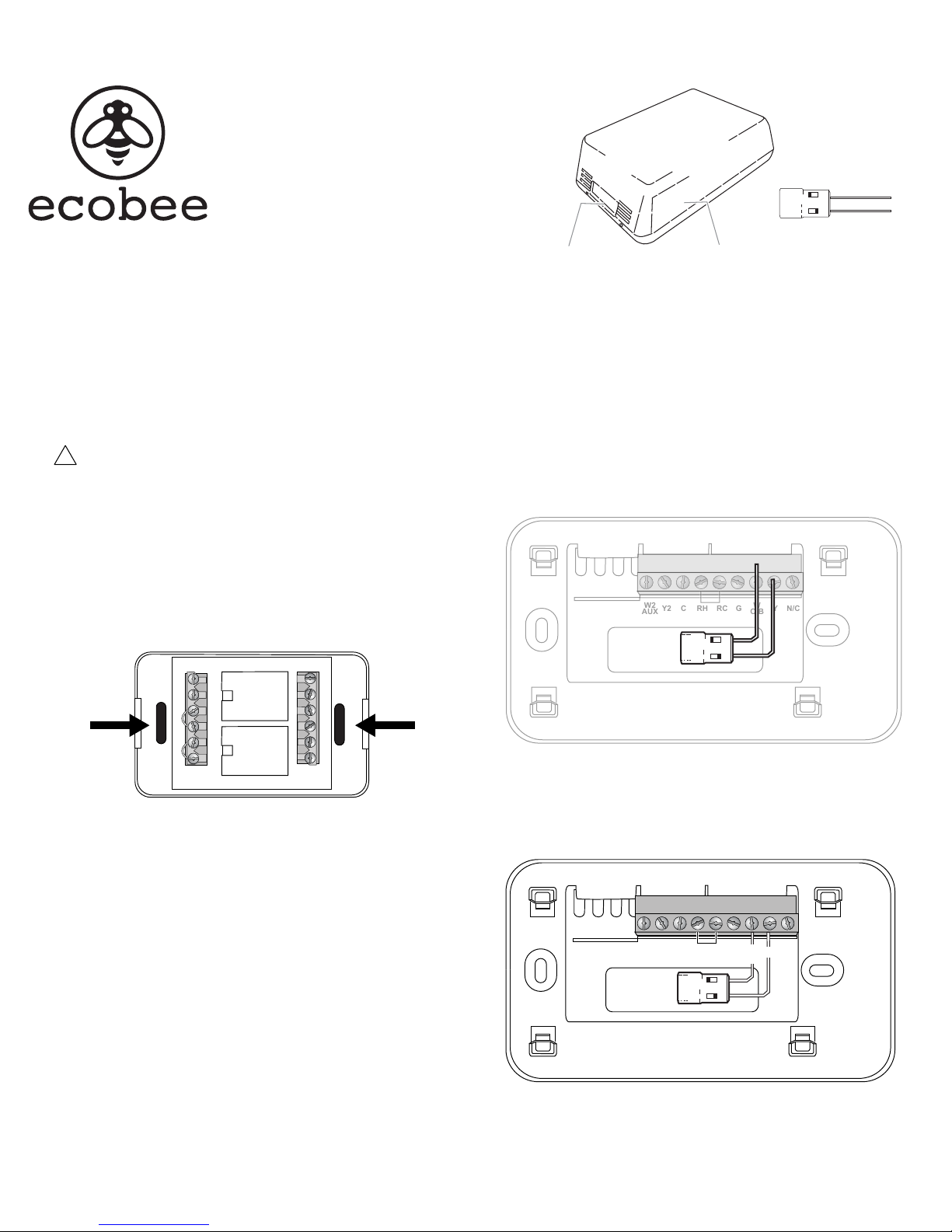
Power Extender Kit
User Manual
Power Extender Kit
Wiring Harness
A common wire (C) is required for
5-wire thermostats. If there are only 4
wires to your existing thermostat (i.e.
there is no C wire), you can use the
ecobee Power Extender Kit to power
your thermostat.
Step 1. Install Wiring Harness
The Power Extender wiring harness must be installed in an indoor, dry
location, near the HVAC equipment. When choosing a location, the
distance between the wiring harness and the HVAC equipment must not
exceed 24 inches (0.6 m) .
This equipment is sensitive to electrostatic discharge (ESD). Before
!
starting, discharge your body of static electricity by touching a
grounded metal object. Always hold the devices by their edges
and do not touch any of the internal components.
1. Power o the HVAC equipment.
2. Remove the top cover of the wiring harness by gently squeezing its
sides.
3. Use 2 #6 pan-head screws or double-sided adhesive to attach the
wiring harness to a at surface (for example, the furnace casing).
Diode
Wiring Channel
Removeable Cover
Step 2. Install Diode
The diode is designed to be installed behind the thermostat, within the
thermostat’s backpanel wire opening.
1. Use your ngers to gently pry the thermostat away from its base.
2. Using the thermostat’s backpanel wire opening as a guide, gently
bend the diode wires 90 degrees so that they can be inserted into the
W O/B and Y terminals:
The diode itself should stay within the wire opening.
Thermostat Side
Mounting Hole
STAT EQUIP
G C W Y RH RC
HVAC Side
G C W Y RH RC
Mounting Hole
W
Y
3. Clip the diode legs so that you can insert them into the W and Y
terminals. DO NOT over clip the legs.
4. Connect the diode legs to the W O/B and Y terminals.
W2
AUX
W
Y
O/B
N/CGRCRHCY2
W
Y
Page 2
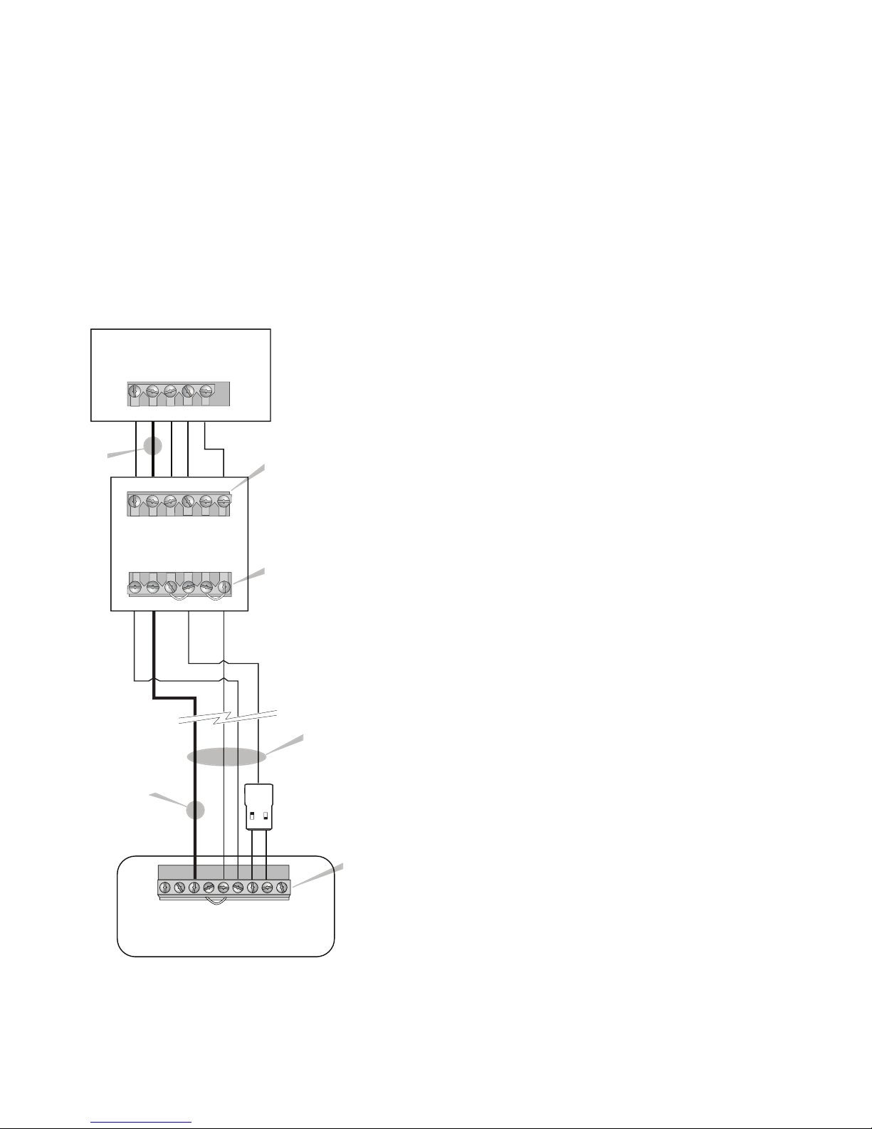
Step 3. Connect the Wires
The next step is to connect the wires between the thermostat, diode, wiring
harness, and HVAC equipment.
1. Connect the C wire coming from the thermostat to the C terminal on the
STAT side of the wiring harness. You can repurpose the wire that would
have been connected to W on a 4-wire thermostat.
2. Connect the RC/RH and G wires from the thermostat to the RC/RH and G
terminals on the STAT side of the wiring harness.
3. Connect the output from the diode to the Y terminal on the STAT side
of the wiring harness. You can re-use the wire that would have been
connected to Y on a 4-wire thermostat.
4. Connect the RC/RH, G (fan), Y, C, and W wires on the EQUIP side of the
wiring harness to the matching terminals on your air hander.
Air Handler
G C W Y R
Step 4. Power On the System
After you have completed the wiring, you can power on and test the system.
1. Re-attach the thermostat to the backplate. Ensure that the pins on the
thermostat align with the terminal block on the backplate.
2. Power on the HVAC equipment. The thermostat should automatically
power on.
3. Test your wiring by alternately adjusting the set temperature and running
the dierent heat, cool, and fan modes.
4. Once you are satised the wiring is correct, re-attach the wiring harness’s
front cover. Make sure the wires exit the module via the wire channel.
5. Re-attach any cover panels that you previously removed on the HVAC
equipment
Need Help?
Contact us at:
Toll free 1.877.932.6233
support@ecobee.com
www.ecobee.com
477 Richmond Street West | 2nd Floor.
Toronto, Ontario , Canada M5V 3E7
New wire
C (existing wire
taken from W)
G C W Y RH RC
Wiring Harness
STAT EQUIP
G C W Y RH RC
W2
AUX
Thermostat Backplate
RC, RH, G (fan), Y & W
connect as usual.
C is a new wire that needs
to be added since there
is no common wire.
RC, RH, & G (fan) connect
as usual
Y is the only wire used for Y & W
C is the repurposed wire
(wire taken from W)
Existing 4 wires
(in wall)
Diode connects to Y & W
Diode
Diode output connects
W
Y
to Y on wiring harness
W
YN/C
GRCRHCY2
O/B
Terminals
for 5-wire
thermostat
Product Specications
Environmental
For indoor use only
Temperature: -40°F to 160°F (-40°C to 70°C)
Humidity: 5-95% RH (non-condensing)
Dimensions
3.3 x 2.0 x 1.0 inches (84 x 52 x 26 mm)
Electrical
Input: 18 to 30 VAC (50 or 60 Hz), 30mA@24V
Output: 18 to 30 VAC (50 or 60 Hz) 2A per terminal
3-Year Limited Warranty
ecobee w arrants that for a p eriod of three (3) year s from the date of purc hase by the consumer (“ Customer”),
the ecob ee Power Extend er Kit (the“Produ ct”) shall b e free of defec ts in materials and wo rkmanship under
normal us e and service. D uring the warrant y period, eco bee shall, at its op tion, repair or rep lace any defecti ve
produc ts, at no charge. Any r eplacement and /or repai red device are warr anted for the rema inder of the
origina l warranty or nin ety (90) days, which ever is longer.
If the pro duct is defect ive, contact the su pplier from who m the product was p urchased to obtai n an
equival ent replacement p roduct, prov ided the supplie r determines that t he returned Prod uct is defect ive and
the Custom er is otherwise e ligible to receiv e a replacement pro duct;
This warr anty does not cove r removal or reinst allation costs an d shall not apply if th e damages were fou nd to
be cause d by something oth er than defect s in materials or work manship, includi ng without limit ation, if the
product:
• was oper ated/stored in abn ormal use or mainte nance conditions;
• is repaire d, modied or al tered, unless eco bee expressly a uthorizes such re pair, modication o r
alterati on in writing;
• was subje ct to abuse, negl ect, electr ical fault, impr oper handling, a ccident or acts of n ature;
• was installed improperly.
ecobee ’s sole responsibi lity shall be to rep air or replace the Pr oduct within th e terms stated abov e. ECOBEE
SHALL NOT BE LI ABLE FOR ANY LOSS OR DAMAGE O F ANY KIND, INCLUDING A NY SPECIAL, INCIDEN TAL OR
CONSEQUEN TIAL DAMAGES RESULTING , DIRECTLY OR INDIR ECTLY, FROM ANY B REACH OF ANY WARRANT Y,
EXPRESS O R IMPLIED, OR ANY OTHER FAILUR E OF THIS PRODUC T. Some US st ates and Canadian p rovinces
do not allow t he exclusion or lim itation of incide ntal or conseque ntial damages, so t he above limitatio n
or exclusi on may not apply to you . ecobee’s respon sibility for mal functions and d efects in mate rials and
workman ship is limited to rep air and replaceme nt as set forth in th is warranty sta tement. All expre ss and
implied w arranties for th e product, incl uding but not limit ed to any implied war ranties and condi tions of
merchant ability and tn ess for a particu lar purpose, are l imited to the three -year duration o f this limited
warrant y. No warranties, w hether expres s or implied, will a pply after the li mited warrant y period has expi red.
Some US st ates and Canadian pr ovinces do not allow l imitations on how l ong an implied war ranty lasts, s o
this limit ation may not apply. ec obee neither ass umes responsibi lity for nor auth orizes any other pe rson
purpor ting to act on its b ehalf to modif y or to change this war ranty, nor to assume f or it any other warra nty
or liabili ty concerning th is product. Thi s warranty give s you specic right s, and you may also have o ther rights
which var y from jurisdic tion to jurisdic tion. If you have any qu estions regardi ng this warrant y, please w rite
ecobee Cu stomer Servi ce, 477 Richmond St West 2nd Fl oor, Toronto O N M5V 3E7, Canada o r contact custom er
servi ce at 1-877-932-6233 or email at su pport@ecob ee.com.
ecobee® i s a registered tra de-mark of ecob ee, inc. © 2013 ecobee, inc . All rights reser ved.
EB-PEK-01
 Loading...