

Page 1

How to install
your ecobee
Page 2

Download the ecobee app
The ecobee app has instructions, step-by-step videos,
and diagrams customized to your wiring setup. Register
your ecobee after installation to unlock smart features
like Amazon Alexa.
1
Page 3
Important Information
Look out for these icons at the bottom of each step.
They indicate useful tips and important reminders.
TIPS
WARNINGS
2
Page 4
Rc
G
Y1
Y2
O/B
PEK
ACC-
ACC+
W2
W1
R
H
C
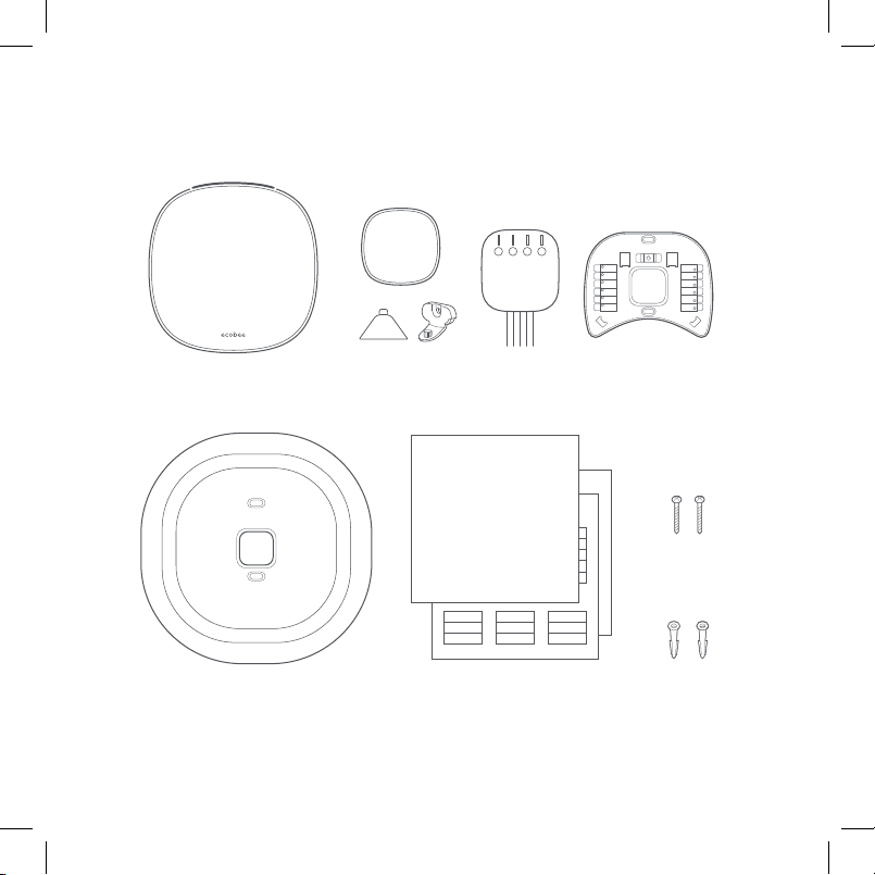
First things first. Here’s what you’ll find in the box:
Rc
G
Y1
Y2
O/B
PEK
H
R
C
W1
W2
ACC-
ACC+
SmartThermostat BackplateSmartSensor, stand,
Tri m p la te
and wall-mount
quick s tart g uide & wire labels
Power Extender
Kit (PEK)
Install guide (this booklet)
Screws
(x2)
Drywall plugs
(x2)
3
Page 5
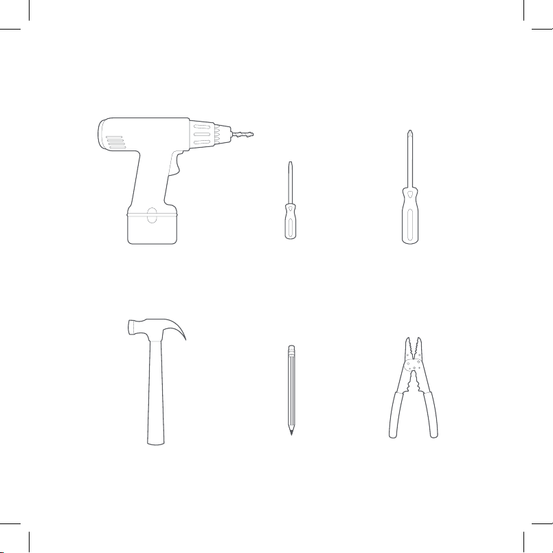
You may also need these tools:
Drill fo r mounting
ancho rs (3/ 16” drill bit)
Hammer Pencil Wire stripper
Small fl athea d
screwdriver
Phillips
screwdriver
4
Page 6
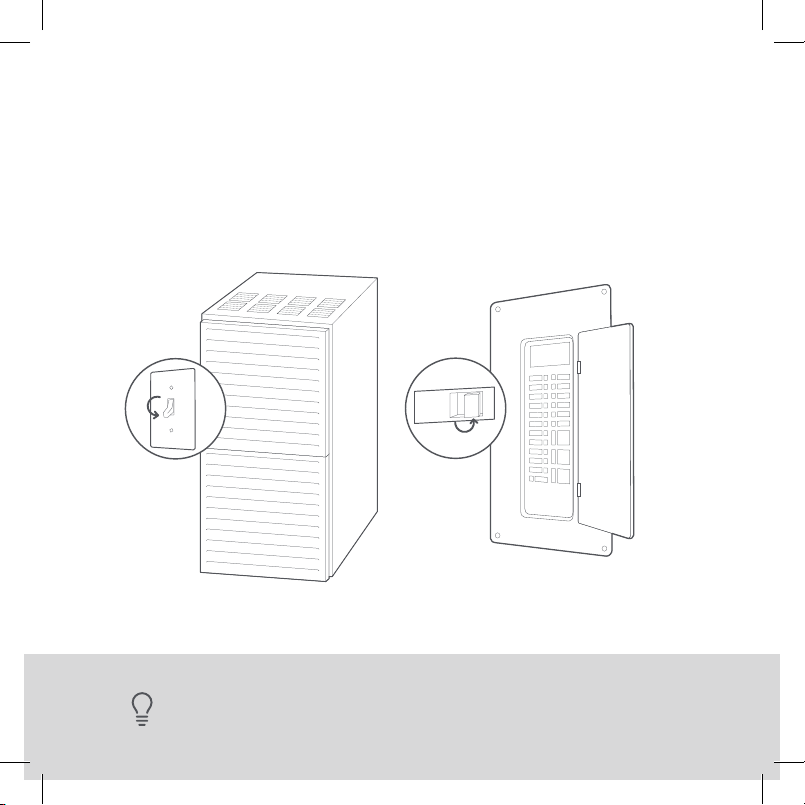
STEP 1
Power o your Heating, Ventilation, and Air Conditioning
(HVAC) system by using the master switch or circuit
breaker box. This is important for your safety.
ON
OFF
OFF
ON
5
utility closet, or behind a wall pa nel near the thermostat.
TIP: Look for your master switch or circuit breaker box in the basement, attic,
Page 7
STEP 2
Confirm your system is o by turning on your heat (during
winter) or your AC (during summer). Wait a few minutes—
you should not feel air coming from your vents.
TIP: If you have a boiler, check to see that the main flame is extinguished.
6
Page 8
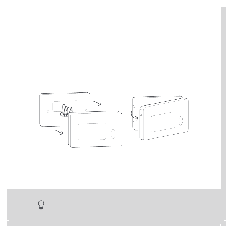
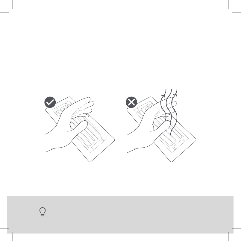
STEP 3
Remove your old thermostat cover from the wall.
TIP: Many thermostats simply pop o or unclip f rom the base, while others
7
may have screws that you will need to remove.
Page 9
L1 L2
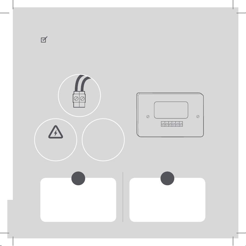
CHECKPOINT: COMPATIBILITY
Does your old thermostat’s backplate have any
of these indicators?
110 VAC
OR
WARNING
HIGH VOLTAGE
YES NO
120 VAC
OR
240 VAC
Sadly, you might
not be compatible.
you can double-check at
ecobee.com/compatibility
Great, please continue
to the NEXT PAGE.
8
Page 10
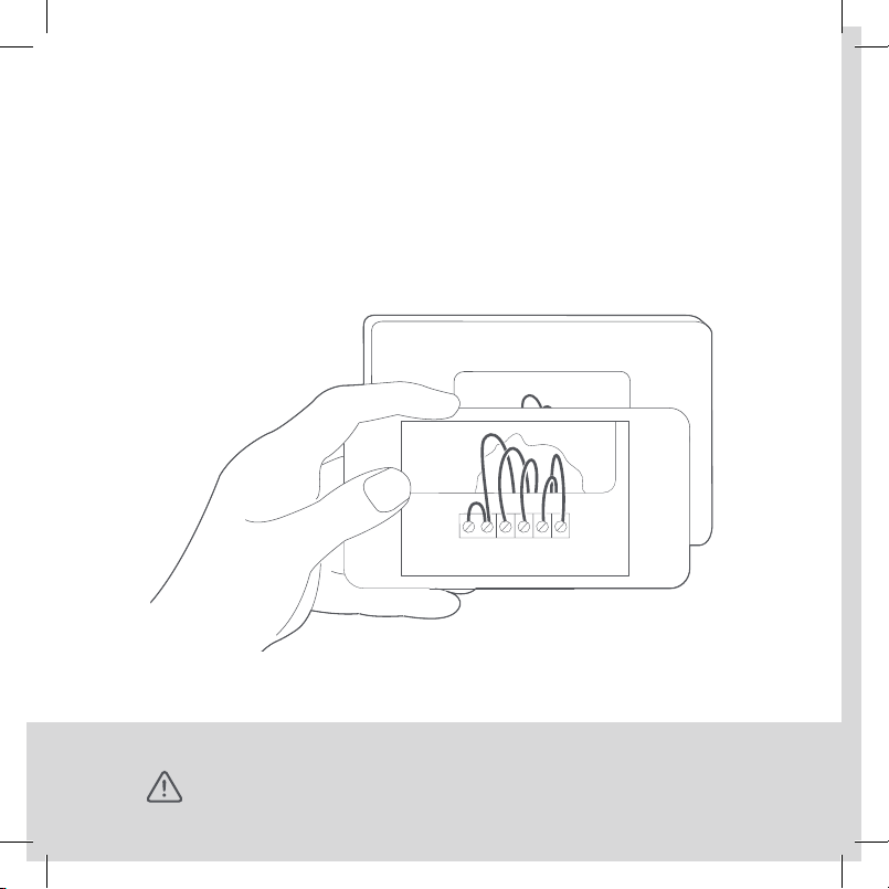
STEP 4
Take a picture of the wires connected to the terminals of
your old thermostat. You may need to reference this photo
later on.
9
WARNING: ecobee is designed for 24VAC with a 2A maximum current.
Do not connect it to line (high) voltage or millivolt systems.
Page 11
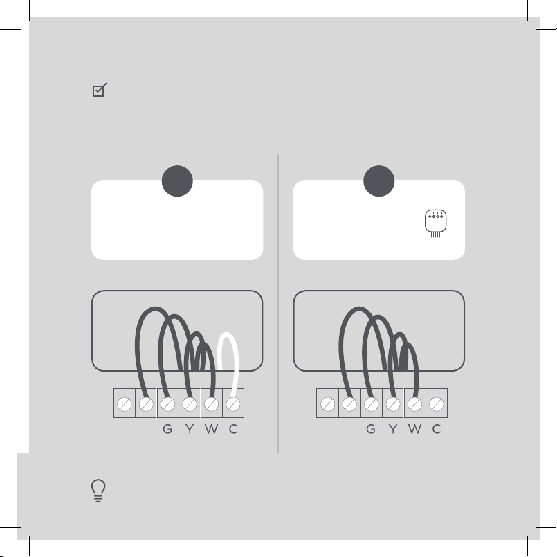
RC RH
CHECKPOINT: C WIRE
Do you have a C wire connected to your old thermostat?
YES NO
Great! Continue
to the NEXT PAGE.
Go to PAGE 24 to
install with a PEK.
RC RHRC RH
TIP: The wiring on your old the rmostat may look dierent—
just check to see if there’s a C wire.
10
Page 12
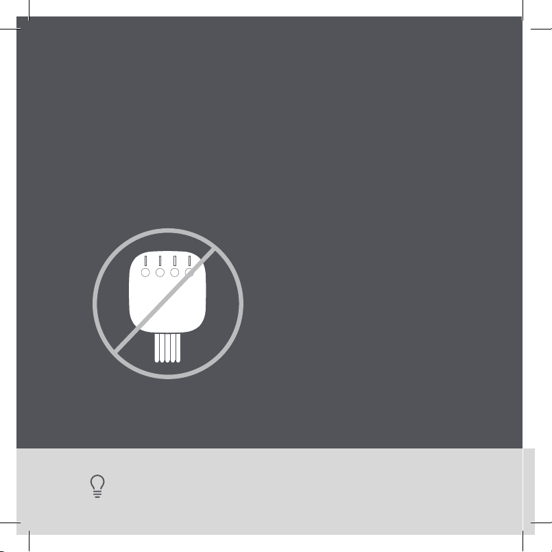
Install your ecobee
with a C wire
If you have a C wire, it will power your ecobee. You won’t
need the Power Extender Kit (PEK) included in the box.
11
TIP: To install accessories (humidifier, dehu midifi er or ventilator) please
refer to the wiring diagrams at ecobee.com/wiring
Page 13
STEP 5
Carefully disconnect and label the wires from your old
thermostat one at a time, using the labels provided.
Rc
Y/Y1
W/W1
RC RH
TIP: If you have a jumper between RC , RH, or R, leave it alone.
Only label the wires that r un from your wall into a terminal block.
12
Page 14
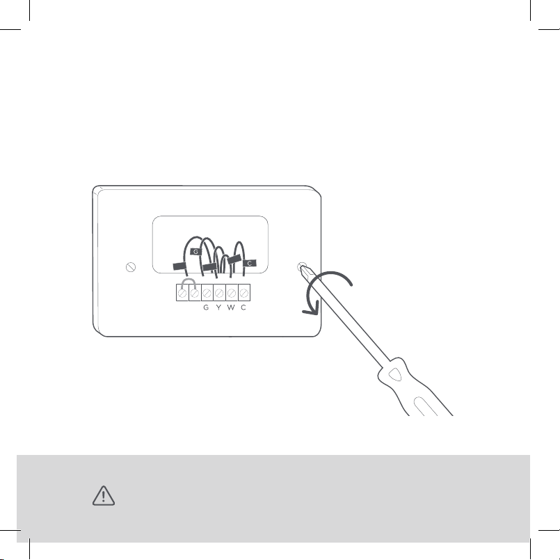
ST E P 6
Unscrew the mounting plate of your old thermostat
to remove it from the wall.
C
R
RC RH
W/W1
Y/Y1
WARNING: Be careful, as some thermostats may contain mercury.
13
Recycle your old th ermostat safely with your local hazardous waste facility.
Page 15
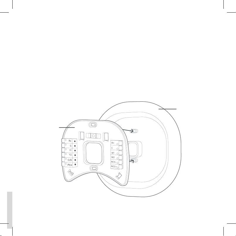
ST E P 7
Decide if you want to use the trim plate with your ecobee.
The trim plate is useful if you want to hide marks or holes
left on the wall by your old thermostat.
If using the trim plate, align the mounting holes on the trim
plate and backplate and press them into place together.
Tri m p la te
Backplate
14
Page 16
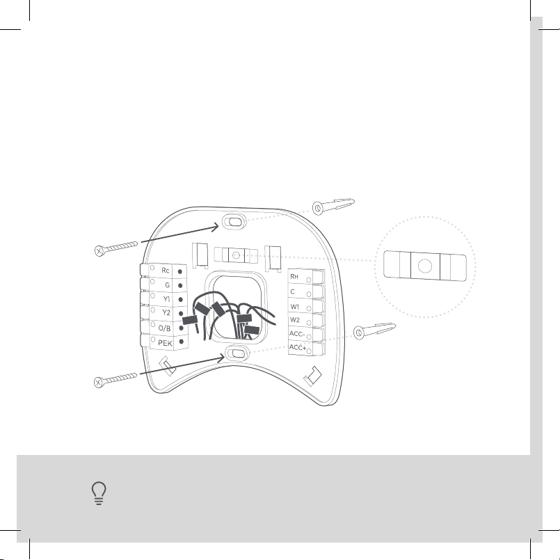
STEP 8
Pull the wires through the hole in the middle of the
backplate and then attach the backplate to the wall
using the drywall anchors and screws provided.
G
Y/Y1
Rc
W/W1
C
15
TIP: Use a 3/ 16" drill bit to drill a hole for the dr ywall anchors.
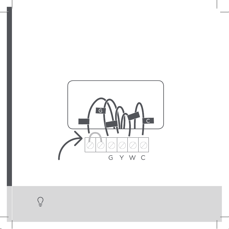
Page 17
ACC-
ACC+
W2
W1
R
H
C
Rc
G
Y1
Y2
O/B
PEK
R
G
C
W/W1
Y/Y1
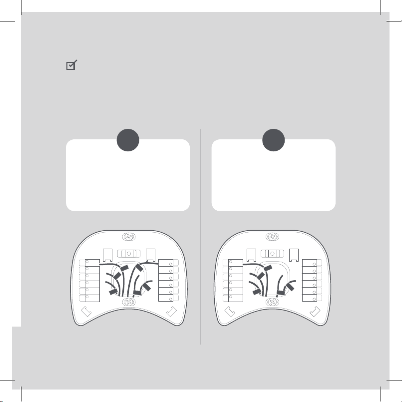
CHECKPOINT: INSERT YOUR R WIRE(S)
Do you have more than one R wire?
(That includes R, RC, and RH)
YES NO
Insert your wires:
R or RC ➔ RC
RH ➔ RH
Rc
G
Y1
Y2
O/B
PEK
R
H
R
G
W/W1
C
Y/Y1
Insert your single wire:
R, RC , or RH ➔ RC
H
R
C
W1
W2
ACC-
ACC+
Rc
Y1
Y2
O/B
PEK
R
G
G
Y/Y1
H
R
C
W1
W/W1
W2
ACC-
C
ACC+
16
Page 18

Rc
G
Y1
Y2
O/B
PEK
ACC-
ACC+
W2
W1
R
H
C
Rc
G
C
W/W1
Y/Y1
STEP 9
Insert your remaining wires into the side (not the front)
of their corresponding terminal blocks.
H
W/W1
R
C
W1
W2
ACC-
ACC+
Rc
G
Y1
Rc
C
G
Y2
O/B
Y/Y1
PEK
TIP: Press the terminal block levers to inser t the wires more easily.
17
Page 19

STEP 10
Tug on the wires gently to ensure they
are securely connected.
TIP: When a wire has been connected correctly,
the lever on that block will lower.
18
Page 20

ST E P 11
Carefully push any excess wires back into the hole
and ensure there are no drafts coming from the hole(s)
in the wall.
TIP: Large holes behind your thermostat will aect temperatu re readings.
Prevent drafts by covering the hole(s).19
Page 21

STEP 12
Gently press your ecobee into the backplate
until it ‘clicks’ into place.
TIP: If the thermostat ‘rocks’ or is not flush with the wall, be sure the excess
wires are pushed all the way into the wall .
20
Page 22

ST E P 13
Turn the power to your HVAC system back on using the
master switch or at the circuit breaker box.
ON
OFF
OFF
ON
21
Page 23

Congratulations, you did it!
Say hi to your new ecobee! To complete your setup and
registrations, follow the instructions on your ecobee screen.
TIP: If your thermostat does not powe r on, please see the troubleshooting
section on PAGE 48 .
22
Page 24

We can help you find a pro
Installation with the Power Extender Kit (PEK) will require
you to handle electrical wiring. If you’d rather leave it up to
a professional, we can help you find one quickly.
ecobee.com/proinstall
23
Page 25

Install your ecobee
without a C wire
If you don’t have a C wire, you’ll need to use the Power
Extender Kit (PEK) included to reliably power your ecobee.
24
Page 26

RC RH
CHECKPOINT: 3 OR 4 WIRES
The Power Extender Kit requires your system to have either
of the following: 4 wires W/W1, Y/Y1, G, and R (or RC or RH)
or 3 wires Y/Y1, G, and R (or RC or RH)
Do you have these wires?
YES NO
Continue to the
NEXT PAGE
The Power Extender Kit
will work with your sys tem!
RC RH
25
Contact us
Visit our compatibility checker
at ecobee.com/compatibility
RC RH
Page 27

STEP 5
Take your Power Extender Kit, wire labels, tools,
your smartphone, and go to your HVAC system.
ecobee wire labels
Label wires at your:
Thermostat Control Board
TIP: Your HVAC system can most often be found in your
basement or you r attic .
26
Page 28

Y
W
G
C
R
STEP 6
Open your HVAC system’s cover to reveal the control board.
Control board
WARNING: HVAC systems contain high voltage wires. Use caution when
working with the control board. If you’d rather leave it up to a professional,
27
we can help you find o ne quickly. Visit ecobee.com/proinstall
Page 29

Y
W
G
C
R
STEP 7
Take a picture of the wires connected to your control board.
You may need to reference this photo later on.
28
Page 30

STEP 8
Label only the R, Y or Y1, G, and W or W1 wires with the
matching labels provided. If you have more than one wire
going into these terminals, only label those going to your
thermostat.
Y
W
G
C
R
Find detailed step-by-step videos at ecobee.com/installation
TIP: If you have wires connected to both Rc and Rh terminals at the control
29
board you may have a two transformer system. Please contact suppor t
to help you with installation: 1.87 7. 93 2 . 623 3 or support@ecobee.com.
R
Y
W
G
Wires going
to your A/C
(ignore these)
Wires going to
your thermostat
Page 31

Y
W
G
C
R
STEP 9
Disconnect the wires labeled R, Y, G, and W from the
control board.
Y
W
G
C
R
W
Y
G
R
30
Page 32

STEP 10
Connect the wires you disconnected from the control
board into their matching gray terminal blocks on the
Power Extender Kit.
W
Y
G
R
Y
G
R
Find detailed step-by-step videos at ecobee.com/installation
W
31
TIP : Press the b uttons to inser t the wires more easily.
Page 33

STEP 11
Tug on the wires gently to ensure they are securely
connected.
W
Y
G
R
W
Y
G
R
TIP: When a wire has been connected correctly, the button
on that block will lower.
32
Page 34

Y
W
G
C
R
STEP 12
Connect the five white wires coming out of your Power
Extender Kit to their corresponding terminals on the
control board.
Y
W
G
C
R
R G Y W
Find detailed step-by-step videos at ecobee.com/installation
33
TIP: On ce again, tug on the wires gently to ensure they a re securely connected.
Page 35

AFTER
CHECKPOINT: POWER EXTENDER KIT
Check that you have installed the Power Extender Kit
correctly. It should be installed between your thermostat
wiring and your control board.
BEFORE
AFTER
34
Page 36

STEP 13
Mount the Power Extender Kit inside your HVAC system,
taking care not to strain the wires. Close the HVAC cover
panel securely and return to your thermostat.
Find detailed step-by-step videos at ecobee.com/installation
TIP: Make sure your HVAC panel is fully closed. Some systems will
35
not turn on if the cover p anel has not been closed properly.
Page 37

STEP 14
Back at your thermostat:
Carefully disconnect and label the wires from your old
thermostat one at a time, using the labels provided.
Rc
Y/Y1
W/W1
RC RH
TIP: I f you have a jumper between Rc, Rh, or R, leave it alone.
Only label the wires that run f rom your wall into a terminal block.
36
Page 38

STEP 15
Unscrew the mounting plate of your old thermostat to
remove it from the wall.
C
R
RC RH
W/W1
Y/Y1
WARNING: Be careful, as some thermostats may contain mercury.
37
Recycle your old th ermostat safely with your local hazardous waste facility.
Page 39

STEP 16
Decide if you want to use the trim plate with your ecobee.
The trim plate is useful if you want to hide marks or holes
left on the wall by your old thermostat.
If using the trim plate, align the mounting holes on the trim
plate and backplate and press them into place together.
Tri m p la te
Backplate
38
Page 40

STEP 17
Pull the wires through the hole in the middle of the backplate
and then attach it to the wall using the drywall anchors and
screws provided.
G
Y/Y1
Rc
W/W1
C
39
TIP : Use a 3/16” drill bit to drill a hole for the dry wall anchors .
Page 41

STEP 18
Remove the Rc, C, and PEK labels from the label sheet and
attach them to the wires as shown below:
R/RC/RH ➔ RC
G ➔ C
Y ➔ PEK
THERMOSTAT CONTROL BOARD
H
R
C
C
W1
W/W1
W2
ACC-
ACC+
O/B
PEK
Rc
Y2
Rc
R
H
G
Y1
G
Y/Y1
PEK
40
Page 42

Rc
G
Y1
Y2
O/B
PEK
ACC-
ACC+
W2
W1
R
H
C
Rc
R
H
G
C
W/W1
PEK
Y/Y1
STEP 19
First, connect these 3 wires as shown: RC , C, PEK.
Then, connect any remaining wires to their
corresponding terminal.
H
Rc
G
Y1
Y2
Rc
R
H
Y/Y1
G
W/W1
O/B
PEK
PEK
TIP : Press the te rminal block levers to insert the wires more easily.
41
R
C
C
W1
W2
ACC-
ACC+
Page 43

CHECKPOINT: DON’T SKIP AHEAD
Did you connect the correct wires to the RC, C, and PEK
terminals, as shown below?
H
Rc
G
Y1
Y2
O/B
PEK
Rc
R
H
Y/Y1
G
W/W1
PEK
YES NO
R
C
C
W1
W2
ACC-
ACC+
Continue to the
NEXT PAGE.
Please ensure that your
wiring is as shown above.
42
Page 44

STEP 20
Tug on the wires gently to ensure they
are securely connected.
43
TIP: When a wire has been connected corre ctly, the lever on that block will lower.
Page 45

STEP 21
Carefully push any excess wires back into the hole and ensure
there are no drafts coming from the hole(s) in the wall.
TIP: Large holes behind your thermostat will aect temperature readings.
Prevent drafts by covering the hole(s).
44
Page 46

STEP 22
Gently press your ecobee into the backplate
until it ‘clicks’ into place.
45
TIP: If the thermostat ‘rocks ’ or is not flush with th e wall, be sure the excess
wires are pushed all the way into the wall .
Page 47

STEP 23
Turn the power to your HVAC system back on using the
master switch or at the circuit breaker box.
ON
OFF
OFF
ON
46
Page 48

Congratulations, you did it!
Say hi to your new ecobee! To complete your setup and
registrations, follow the instructions on your ecobee screen.
47
Page 49

Troubleshooting
48
Page 50

TROUBLESHOOTING
If your ecobee doesn’t turn on, please try these steps:
1. Check that all wires are pro perly
inserted into the terminal blocks
at the thermostat. Tug on the wires
to ensure they are not loose.
49
2. Make sure your HVAC cover panel is
closed. Some systems will not turn
on if the cover panel has not been
closed properly.
Page 51

TROUBLESHOOTING
R
Your R, RC ,
or RH wire
O/B
PEK
Rc
Rc
R
H
G
Y1
Y2
Y/Y1
PEK
H
R
C
G
C
W1
W/W1
W2
ACC-
ACC+
3. If you have only one R wire
(either R, Rc, or Rh), make sure it’s
inserted into the Rc terminal.
4. If you installed the Power Extender
Kit, make sure you inserted the
wires into the correct terminals .
50
Page 52

Still need help?
WE’RE HERE FOR YOU
Have questions or concerns? Get in touch.
1. 87 7. 9 32 . 6 2 3 3
ecobee.com/support
WE CAN HELP YOU FIND A PRO
Installation requires you to uninstall your old device
and handle electrical wiring. If you’d rather leave it up to
a professional, we can help you find one quickly.
ecobee.com/proinstall
INSTALLING ACCESSORIES?
To install accessories (humidifier, dehumidifier or ventilator)
please refer to the wiring diagrams at ecobee.com/wiring
51
Page 53

LEGAL
Approvals
This pro duct was d esigned and bu ilt in acco rdance
to RoHS di rective 20 02/95/EC and co ntains no
hazard ous subs tances a s define d by this dire ctive.
FCC Compliance Statement Compliance Notice:
This equ ipment has bee n tested and found to
comply wi th the limits for a Cl ass B digit al device,
pursua nt to part 15 of the FCC R ules. These li mits
are desi gned to prov ide reaso nable protecti on
against harmful interference in a residential
installation. This equipment generates, uses and can
radiate r adio fre quency e nergy and, if no t installed
and use d in accord ance with th e instruction s, may
cause h armful i nterference to ra dio communic ations.
However, ther e is no guarantee th at interferen ce will
not occu r in a parti cular install ation. If this eq uipmen t
does ca use harmful inte rference to rad io or
televisi on reception, wh ich can be determ ined by
turnin g the equipment o and on, the user i s
encour aged to try to corre ct the inte rference by one
or more of th e following meas ures:
· Reorient o r relocat e the recei ving anten na.
· Increase th e separation bet ween the equip ment
and receiver.
· Connect t he equip ment into an outlet o n a circuit
diere nt from that to which th e receiver is
connected.
· Consult the d ealer or an exper ienced radio/ TV
technician for help.
This devi ce compli es with part 15 of FCC r ules.
Opera tion is sub ject to the f ollowing t wo conditions:
1. This devic e may not cause har mful inte rferen ce.
2. This devic e must acc ept any inte rferen ce received,
includ ing interferen ce that may cause un desired
operation.
Chang e or modifi cations that are n ot expressly
approved by t he manufactu rer could vo id the user’s
author ity to ope rate the equ ipment.
RF Exposure Information:
This equ ipment compli es with FCC radiatio n
exposur e limits se t forth fo r an uncont rolled
environ ment. In o rder to avoid the poss ibility o f
exceedi ng the FCC ra dio freq uency exp osure limits,
human p roximity to t he antenn a shall not be less
than 8 inc hes during norm al operation .
Innovation, Science and Economic Development
Canad a (ISED) | Compliance Noti ce:
This device contains licence-exempt tran smitter(s)/
receive r(s) that comply w ith Innova tion, Sc ience an d
Economic Development Canada’s licence-exempt
RSS(s). Oper ation is subjec t to the follow ing two
conditions:
1. This d evice may not cause i nterference.
2. This d evice must accept a ny interference ,
includ ing interfere nce that may c ause undesire d
operat ion of the dev ice.
Innovation, Sciences et Développement
économ ique Canada (IS DE) | Avis de co nformité:
L’émetteur/récepteur exempt de licence contenu
dans le p résent ap pareil est confo rme aux CNR
d’Innovation, Sciences et Développement
52
Page 54

économique Canada applicables aux appareils radio
exempts d e licence . L’exploita tion est au torisée a ux
deux con ditions suivante s :
1. L’appareil n e doit pas pr oduire d e brouill age;
2. L’appareil do it accepter tout bro uillage
radioé lectrique sub i, même si le brou illage es t
susceptible d’en compromettre le fonctionnement.
RF Exposure Statement:
This equ ipment compli es with IC RSS-102 r adiation
exposur e limits se t forth fo r an uncont rolled
environ ment. Th is transmitter m ust be ins talled to
provide a s eparati on dista nce of at lea st 8 inches
from all p ersons a nd must not be coll ocated or
operat ing in conj unction with any ot her anten na or
tra nsm itter.
Énoncé s ur l’exposition aux fréq uences radio :
Cet équipement est conforme aux limites
d’exposi tion aux fréque nces radio d’ IC RSS-102
définies pour un environnement non contrôlé. Cet
émette ur doit être insta llé à au moins 20 cm d e toute
perso nne et ne doit pas êt re colocalisé ou f onctionner
en association avec une autre antenne ou émetteur.
FCC ID: WR 92221123 114
IC: 7981A-2221123114
CAN IC ES-3 (B)/N MB-3(B)
Warning: Changes or modifications not expressly
approved by e cobee Inc. co uld void the u ser’s
author ity to ope rate the equ ipment
Avertiss ement : le s changement s qui ne sont pas
express ément au torisés par ecob ee Inc. pourra ient
annul er votre droi t d’usag e du matériel..
3-Year Limited Warranty
ecobe e warrant s that for a period of t hree (3) ye ars
from the d ate of purch ase by the consume r
(“Cus tomer” ), the ecobee (the “ Product” ) shall be
free of de fects in m aterials and wor kmansh ip under
norma l use and se rvice. D uring the warra nty peri od,
ecobe e shall, at i ts option, repa ir or repl ace any
defec tive Produ cts, at n o charge . Any replacemen t
and/or rep aired dev ice are war ranted for t he
remain der of the origina l warranty or nin ety (90)
days, whi chever is longer. A pro of-of-purchase wi ll
be requi red from the Custo mer in ord er for eco bee
to provide a re placement an d/or repair ed device .
This Warr anty is val id only for Produ ct insta lled in
the coun try in whi ch it is purc hased.
If the pro duct is d efective , call Customer S ervice at
1-87 7-932-62 33. eco bee will m ake the dete rminati on
whethe r a replace ment product c an be sent to you
or wheth er the prod uct should be re turned to o ur
address.
In the event o f a failur e of a Produc t, Customer may :
a. If Custom er did not purcha se the Prod uct directly
from eco bee, con tact the t hird par ty contractor
from who m the Product was p urchase d to obtain
an equivalent replacement product, provided the
contrac tor determines t hat the retu rned Product
is defec tive and Custome r is other wise elig ible to
receive a replacement product;
b. Contact e cobee di rectly fo r servic e assistance at
1-87 7-932-62 33 and eco bee will make the
determination whether an advance equivalent
replac ement Pro duct can be sen t to Custom er
with retur n shippi ng suppl ies (in whi ch case a
hold sha ll be put on Custom er’s credit card f or the
value of th e replacement P roduct until eco bee
has received the defective Product). Product
should b e returned to our ad dress. If the ret urned
Produc t is found by ecobe e to be defec tive and
Custom er is othe rwise el igible to re ceive a
replac ement pr oduct , no amoun t shall be charge d
to Custom er’s cred it card; or
53
Page 55

c. Ship the d efective P roduct direct ly to ecobe e, in
which ca se Customer sha ll contac t ecobee
direct ly at 1-87 7-93 2-623 3, so ecob ee can make
the required shipping arrangements. Upon receipt
of the defe ctive Product , ecobee w ill ship an
equivalent replacement product to Customer,
provide d the retur ned Prod uct is fou nd by ecobee
to be defec tive and Custome r is otherwise el igible
to receive a re placement pro duct.
This war ranty do es not cover removal o r
reinst allatio n costs an d shall no t apply if th e
damag es were fou nd to be cau sed by some thing
other th an defec ts in materials or wo rkmanship,
includ ing without limit ation, if the Prod uct:
· Was operated /store d in abnormal us e or
maintenance conditions;
· Is repaired , modified or al tered, un less ecobee
express ly author izes such repair, mod ification or
alteration in writing;
· Was subject to a buse, neglec t, electrica l fault,
improp er handling, a ccident o r acts of nature;
· Was not instal led by a licensed He ating Ventilating
and Air C onditio ning (HVAC) co ntracto r; or
· Was installe d improperly.
ecobe e’s sole res ponsib ility sha ll be to repair or
replac e the Produ ct within the term s stated ab ove.
ECOBEE S HALL NOT BE LIAB LE FOR ANY LOSS
OR DAMAGE O F ANY KIND, IN CLUDING ANY
SPECIAL, INCIDENTAL OR CONSEQUENTIAL
DAMAGES RESULTING, DIRECTLY OR INDIRECTLY,
FROM AN Y BREACH OF ANY WAR RANTY,
EXPR ESS OR IM PLIED, OR ANY OT HER FAILU RE
OF THIS P RODUCT. Some U S states an d Canadian
province s do not allow the exclu sion or limitatio n of
incide ntal or consequ ential damage s, so the above
limitat ion or exclu sion may no t apply to you .
ecobe e’s respon sibility for mal functions an d defect s
in materi als and wo rkmans hip is limi ted to repai r
and repl acement as set fo rth in this w arrant y
statem ent. All ex press an d implie d warranti es for
the prod uct, in cluding b ut not limited to any im plied
warranties and conditions of merchantability and
fitness f or a parti cular pu rpose, are limite d to the
three- year dura tion of this l imited wa rranty. No
warranties, whether expressed or implied, will apply
after th e limited warrant y period has expi red. Som e
US states a nd Canadian p rovinces do not all ow
limitat ions on how l ong an implied wa rranty lasts ,
so this lim itation may not app ly.
ecobe e neither a ssumes respon sibility for no r
author izes any othe r person purpo rting to ac t on its
behal f to modif y or to chang e this warranty, no r to
assume f or it any other warra nty or liabilit y
concerning this product.
This war ranty giv es you spec ific right s, and you may
also have oth er rights which v ary from j urisdiction to
jurisd iction . If you have any questi ons rega rding this
warran ty, please w rite to ecob ee Custom er Service.
Legal Notice
Use of the H omeKi t™ logo mea ns that an electr onic
access ory has b een desi gned to con nect specifi cally
to iPod®, iPhone®, or iPad®, respec tively, and has
been ce rtified by t he develo per to meet A pple®
perfo rmance s tanda rds. App le is not responsi ble for
the oper ation of this device o r its comp liance wi th
safety and regulatory standards. Please note that
the use of th is accessory wit h iPod, i Phone , or iPad
may aect wireless performance. Apple, iPhone,
iPad, and iPod touch are trademarks of Apple Inc.,
registe red in the U.S. a nd other countri es. Hom eKit
is a trade mark of Ap ple Inc .
54
Page 56

We’re here to help.
ecobee.com
support@ecobee.com
1. 87 7. 9 32 . 6 2 3 3
© 2019 ecobee, Inc. All rights reserved. ecobee
and the ecobee logo are trademarks of ecobee Inc.,
registered in the U.S . and other countries.
770-00092
 Loading...