

Page 1

Installation guide
Page 2

Page 3

Welcome!
If you have questions, we have answers.
Visit ecobee.com/Support/ecobee3 for tutorials, how-to
videos and FAQs.
Technical support is also available by email or by phone:
1.877.932.6233 (North America)
1.647.428.2220 (International)
Compatible systems
ecobee3 works with most centralized residential heating
and cooling systems.
Heating: up to 2 stages
Cooling: up to 2 stages
Heat pumps: 1 or 2 stages + up to 2 stages auxiliary heat
Accessories: Dehumidifier, humidifier or ventilation device
3
Page 4
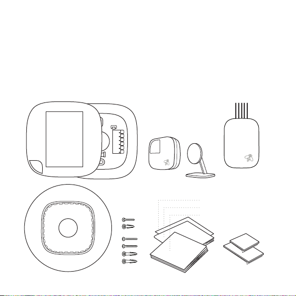
Items included in box
A
ecobee3 thermostat with
back plate and trim plate
B
Remote Sensor and stand
C
Power Extender Kit
(optional)
A
D
4
D
Large trim plate
E
Screws and drywall plugs
F
Information booklets
G
Double-sided adhesives
B
E
C
wire labels
Installation Guide
Quick Start Guide
GF
Page 5
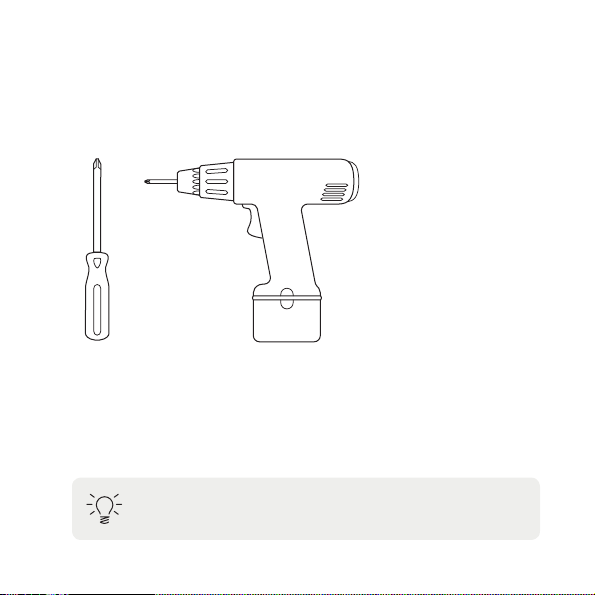
Items you’ll need
A
Phillips screwdriver
B
Drill for mounting anchors with ⁄ inch drill bit
A B
Tip: Review all the instructions before you start to
ensure that there are no surprises during installation.
5
Page 6

Overview of steps
Installing your ecobee3 home climate system is easy. Just
follow these steps and you’ll be done before you know it.
Step 1
page 8
Power o your HVAC system
Before doing anything else, power o your system.
Step 2
page 9
Step 3
page 11
Step 4
page 14
Step 5
page 16
Step 6
page 18
Step 7
page 19
6
Label the wires
Label each wire with the provided stickers.
Install Power Extender Kit
The PEK is not required for all installs. If you have a wire
labelled “C” or “common”, skip to step 4.
Attach back plate to wall
Secure the back plate to your wall with the provided screws.
Connect wires to ecobee3
Use the stickers from step 2 as a guide and insert the wires
into ecobee3 terminal blocks.
Power on your HVAC system
Power back on your HVAC equipment. Your ecobee3 will
automatically power on and guide you through setup.
Install remote sensor
Stand in front of your ecobee3 and pull the plastic tab
on the remote sensor to automatically connect it to your
thermostat.
Page 7
Terminal descriptions
G Fan
Rc Cool transformer
Rh Heat transformer
O/B Heat pump reversing valve
Y Y1, Y2: Used for 1 - 2 stages of conventional A/C
W W1, W2: Used for 1 - 2 stages of conventional heat
C 24VAC common
ACC Accessory (+/-): Used for dehumidifiers,
or 1 - 2 stages of heat pump compressor
or 1 - 2 stages of auxiliary heat with heat pump
humidifiers, ventilators, HRVs or ERVs
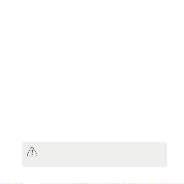
Warning! ecobee3 is designed for 24VAC with a 2A
maximum current. Do not connect it to line (high)
voltage or millivolt systems.
7
Page 8
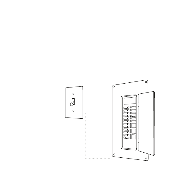
Step 1. Power o your HVAC system
Before doing anything else, power o your system. If your
HVAC equipment doesn’t have a master switch, go to your
circuit breaker box and turn o the breaker.
Verify that the equipment is o by attempting to adjust
the temperature your existing thermostat. The thermostat
will show the temperature change but your cooling or
heating should not come on.
Power o your system either
using the master switch or at
the circuit breaker box.
8
Page 9
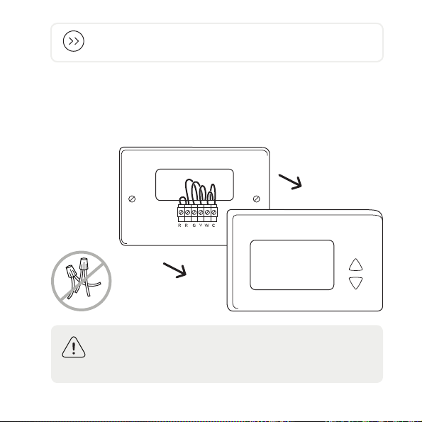
Note: If you don’t have an existing thermostat, skip to
step 3.
Step 2. Label the wires
Remove the cover from your old thermostat. Most snap o
easily but some may be attached by screws.
HC
110/120V
Warning! If your old thermostat has 110/120V wires
capped with wire nuts, it is a high voltage system and is
not compatible with your ecobee3.
9
Page 10
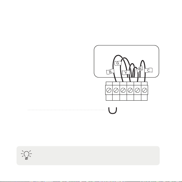
1. Look at the wires coming out of the wall. Take a
picture for reference.
2. Using the old thermostat base as a guide, label each
wire going into your old thermostat with the provided
stickers.
Discard any jumper wires
between Rh, Rc, or R. Your
ecobee3 does not need them.
RC RH G Y W C
3. If you have used the wire label C, please skip step 3
and proceed directly to step 4. If you have NOT used
the wire label C, proceed to Step 3: Install Power
Extender Kit (PEK).
Tip: If the wires have completely dierent labels, please
call ecobee support to help with wiring.
10
Page 11
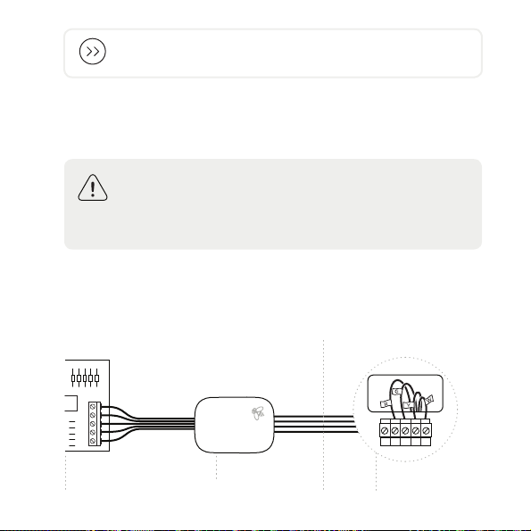
Note: The PEK is not required for all installs. If you have
a wire labelled “C” at your thermostat, skip to step 4.
Step 3. Install Power Extender Kit
(PEK)
Warning! This step requires you to work with wiring at
your HVAC Control Board. If you are not comfortable
working with your HVAC wiring, contact ecobee
customer support or hire a professional installer.
Some thermostats do not have a C-wire. The C-wire is
used to reliably provide power to the thermostat. In this
case, the PEK can use the existing wires to power your
thermostat.
At your thermostatAt your utility closet
R
G
Y
W
C
HVAC
control board
Power
Extender Kit
RC RH G Y W
Existing
thermostat wires
11
Page 12
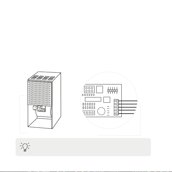
The PEK requires your system to have the following wires:
• 4 wires: W, Y, G, and R (or Rc or Rh), or
• 3 wires: Y, G, and R (or Rc or Rh)
1. Remove the cover panel from your HVAC equipment.
2. Locate the control board and take a picture of it for
reference.
3. Using the stickers provided, label the wires on the
control board leading to the thermostat.
Control board
R
G
Y
W
C
Furnace (cover panel removed)
Tip: The control board will generally have R, G, Y, W, C
terminal designations.
12
Wires to thermostat
Page 13
Pre-installed wires
to HVAC control board
Power Extender Kit basePower Extender Kit cover
Wires connecting
to thermostat
R
C
G
W
Y
W
Y
G
G
R
R
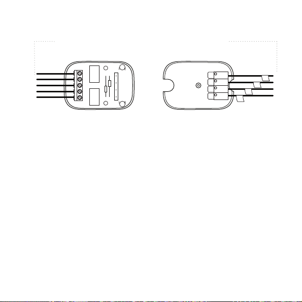
4. Open up the PEK. It has two rows of terminals (one
side is for thermostat connections, the other side,
pre-wired, is for the control board connections).
5. Disconnect the wires from the control board and
reconnect them to the corresponding terminals on the
thermostat side of the PEK.
6. Using the wires provided with the PEK, connect the
terminals on the equipment side of the PEK to the
corresponding terminals on the control board.
7. Close the PEK and use the provided double-sided
tape on the back to mount it in a dry location that
doesn’t strain the wires. The PEK can be safely placed
on any free space on an inside wall of your HVAC unit.
8. Close the HVAC cover panel.
W
Y
13
Page 14
Step 4. Attach back plate to wall
1. Gently remove the old thermostat base by unscrewing
it from the wall. Make sure the wires do not fall back
into the wall.
2. Position the back plate of your ecobee3 on your wall,
using the built-in level to make sure it’s straight. Mark
the mounting holes on your wall in pencil.
3. Drill mounting holes for the drywall anchors.
4. The back plate must be used with a trim plate.If the
smaller trim plate does not cover the marks left by the
previous thermostat, you can attach the larger trim
plate instead.
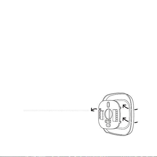
Remove the back plate by gently
pushing the back of its left side
towards you.
14
Page 15
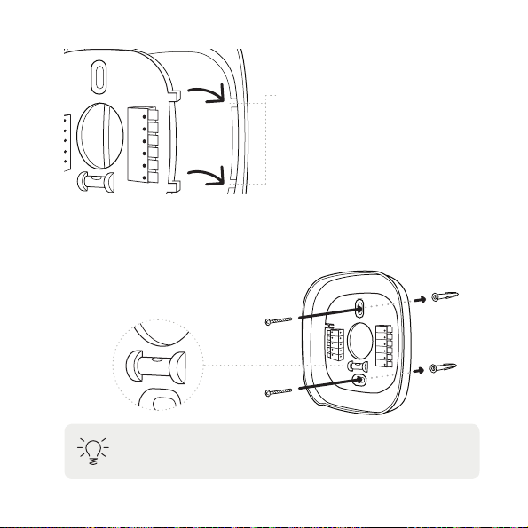
Insert the back plate using the tabs
on the right as a guide. It will snap
into place when correctly inserted.
Secure the back plate
Use the drywall anchors and screws provided to secure
the back plate to the wall.
Tip: ensure the back plate is straight by centering the
bubble on the built-in level.
15
Page 16
Step 5. Connect wires to ecobee3
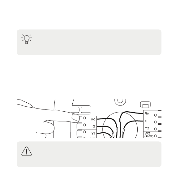
Tip: If you are replacing an existing thermostat, use the
stickers as a guide when inserting the wires into the
ecobee3 terminal blocks.
The wires from the wall should plug easily into the terminal
blocks. To release a wire, press down on the lever.
When installed correctly, the release lever of the terminal
block will lower to indicate engagement. Tug on the wires
to ensure they are engaged in the terminal.
Warning! If you installed the PEK in step 3, the R (or
Rc or Rh) wire must connect to the Rc terminal on the
ecobee3, or the thermostat will not power on.
16
Page 17
If you need help with the wiring, refer to the reference
diagrams at the back of this guide:
• For conventional heating and cooling systems, see
page 26.
• For heat pumps (air or geothermal), see page 27.
• For boilers or radiant heat systems, see page 28.
• For accessory devices like dehumidifiers, humidifiers,
or ventilators, see page 29.
• For PEK installations, see page 30.
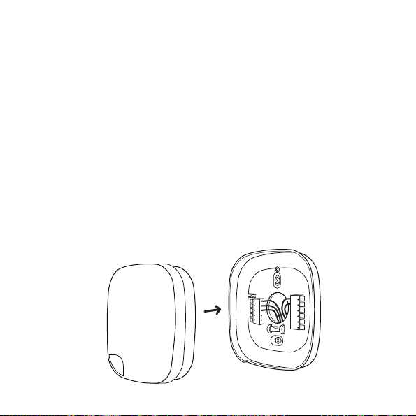
Attach thermostat
Push any excess wires back into the wall, and connect your
ecobee3 thermostat to the base.
17
Page 18
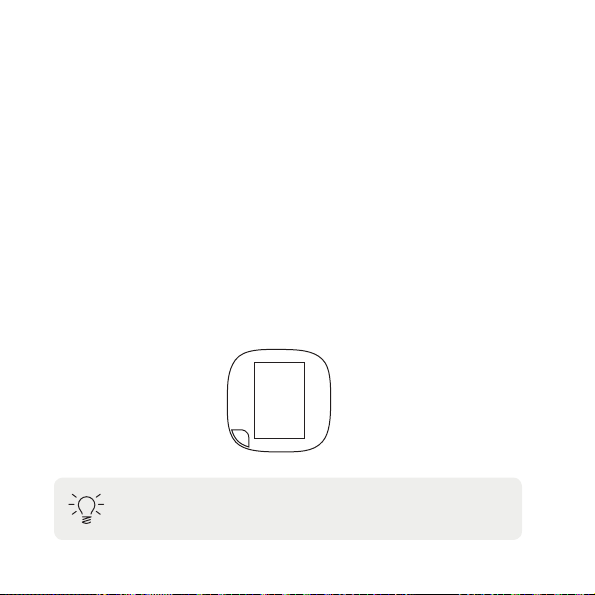
Step 6. Power on ecobee3
Power your HVAC equipment back on. Your ecobee3 will
automatically power on. If your ecobee3 does not power
on, see page 24 for troubleshooting.
Follow the on-screen instructions. ecobee3 will guide you
through the setup, which includes:
• Equipment configuration (HVAC and accessories)
• Set your preferences (choose °F or °Cheatingand
coolingsetpointsthermostatname)
• Set up wi-fi
• Register your ecobee3 online
hi
Tip: The settings on your ecobee3 can be changed at
any time from the main menu.
18
Page 19
Step 7. Install remote sensor
Ordinary thermostats only read the temperature in one
location. ecobee3 uses multiple temperature readings from
remote sensors to deliver comfort more reliably.
Pair the sensor at the thermostat
1. To activate your remote sensor, ensure your ecobee3
is awake by standing in front of it or touching the
screen.
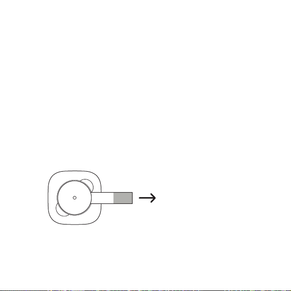
2. Pull the plastic tab on your remote sensor and it will
power on and connect to your ecobee3 automatically.
Stand in front of your ecobee3
and pull the plastic tab on the
remote sensor to automatically
pair it with your thermostat.
19
Page 20
3. Your ecobee3 will detect your remote sensor and ask
you to name it. You can verify a successful connection
on your thermostat. If your sensor does not connect
with the ecobee3, simply remove the battery, wait
2 minutes, and re-insert the battery to restart the
detection process.
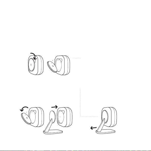
To access the battery, pop the
remote sensor back cover o
using the ridges provided.
To attach the remote sensor
stand, remove the smaller back
cover and pop the stand into
place.
20
To remove the remote sensor
stand, pull the base outwards.
Page 21
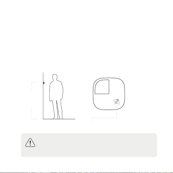
Find a location
Place your remote sensor at a height of approx. 5ft / 1.5m
in an open, high-trac area like a living room or upstairs
hallway (for Smart Home/Away) or a room of your choice
like your baby’s room (for Follow Me). If the sensor is
out of range of your ecobee3 (approx. 45 ft / 13.7 m) the
thermostat will show N/A, meaning it cannot connect to
the remote sensor. When in range, they will automatically
reconnect.
5ft
(1.5m)
Rotate sensor so bee points up
to the right.
Warning! Do not place the remote sensor in direct
sunlight, near vents or window openings as this may
aect the temperature readings.
21
Page 22
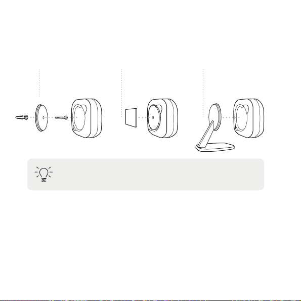
Install the remote sensor
Using the materials provided, install the remote sensor in
one of three ways:
Option 1.
Attach to a wall
using the screw
provided.
Tip: Make sure your remote sensor has an unobstructed
view of the room.
Option 2.
Attach to a wall
using the adhesive
provided.
Option 3.
Place on a flat
surface using the
stand provided.
Congratulations, you’re done!
Register your ecobee3 at ecobee.com to control it from
your smartphone, tablet or desktop, and to access free
online energy management tools.
Download the free ecobee3 mobile app on iTunes and the
Google Play store.
22
Page 23

Menu options
To access the thermostat menu, touch the screen and
press
System
Selects mode of operation: heat/cool/auto/o, fan on/auto
Schedule
Configures temperature according to time and day
Comfort Settings
Configures temperature for dierent occupancy states
(away, home, sleep)
Vacation
Configures temperature for a specific future time period
Settings
Configures display preferences (°F/°C, date, brightness),
wi-fi, and equipment operating parameters (thresholds,
sensors, etc)
Reminders
Displays any reminder or alert messages
About
Displays technical information about your thermostat
23
Page 24

Troubleshooting
If your ecobee3 does not power on, please check the
following:
1. Check that all wires are properly inserted into the
terminal blocks at the thermostat. Tug on the wires to
ensure they are not loose
2. Some HVAC equipment has a safety switch that cuts
o power to the equipment if the equipment cover
panel is not closed properly. Please ensure the cover
panel of the equipment is closed properly
3. If you installed the PEK, ensure R wire is connected
to Rc only and G wire is inserted properly into the
terminal
4. If you have a multi-meter, please check the AC voltage
between Rc and C or Rh and C and ensure it is 24V
5. If your device still does not power on, please call
ecobee support at 1.877.932.6233 (North America),
1.647.428.2220 (International)
24
Page 25

Wiring diagrams
The following pages provide wiring diagrams for common
HVAC equipment configurations.
Need help with your ecobee3 wiring? Find how-to videos
and tutorials on ecobee.com/HowTo
25
Page 26
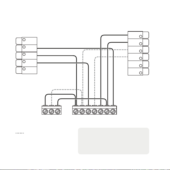
Conventional heating and cooling
Y1 Y2 C Y1 Y2 W1 W2 R C G
(up to 2 stages each)
Rc
G
Y1
W1
(AUX1)
O/B
Air conditioner Furnace
R
H
C
Y2
W2
(AUX2)
ACC+
ACC–
Stage 2 heat and cool
if applicable
26
Note: Do not jumper Rc or Rh,
ecobee3 does this automatically.
R can go into either Rc or Rh
terminals on your ecobee3.
Page 27
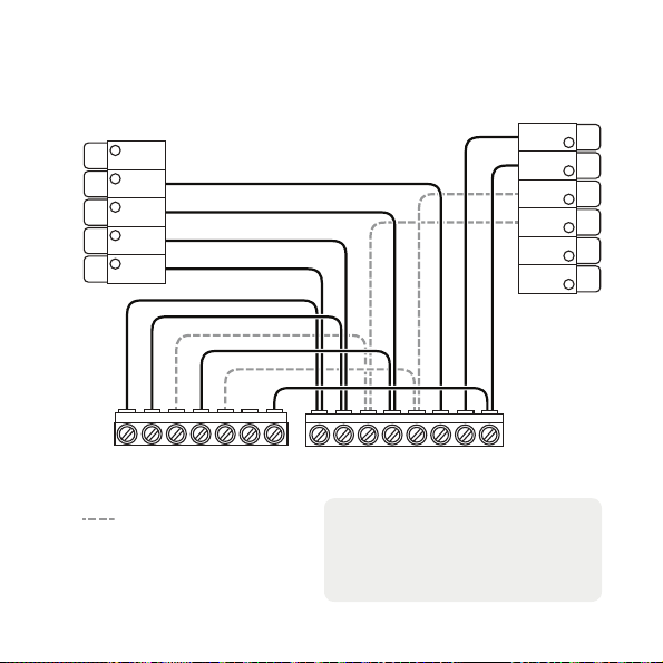
Heat pump (air or geothermal)
with auxiliary heat
Rc
G
Y1
W1
(AUX1)
O/B
W2W1O/B Y1 Y2 R C W1O/B W2 Y1 GY2 R C
Heat pump Air handler
R
H
C
Y2
W2
(AUX2)
ACC+
ACC–
Stage 2 compressor and
auxiliary heat if applicable
Note: Do not jumper Rc or Rh,
ecobee3 does this automatically.
R can go into either Rc or Rh
terminals on your ecobee3.
27
Page 28
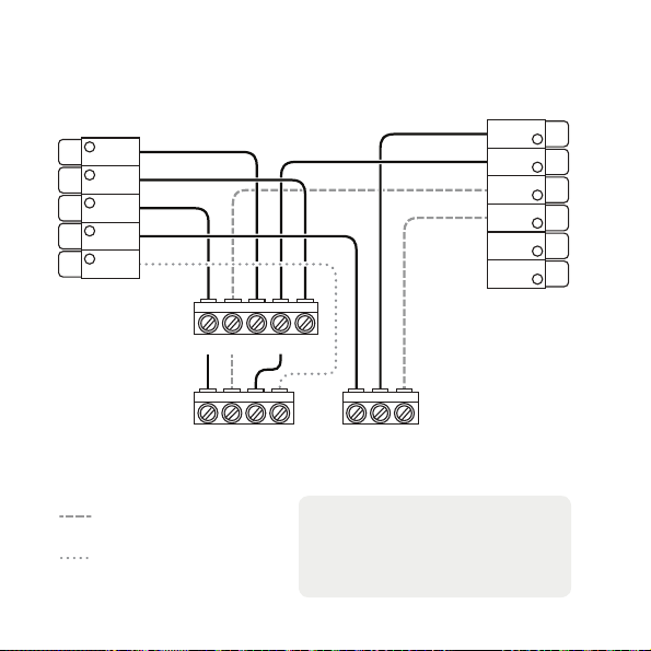
Boiler or radiant system with air handler
and conventional cooling or heat pump
Rc
W1
(AUX1)
O/B
G
Y1
R
C
Y2
W2
(AUX2)
ACC+
ACC–
H
Air handler
Stage 2 heat and cool
if applicable
*Reversing valve for heat
pumps only
28
Y1 Y2 R C G
Y2Y1 C O/B*
Air conditioner
or Heat pump
W1 W2R
Boiler
Note: Do not jumper Rc or Rh,
ecobee3 does this automatically.
R can go into either Rc or Rh
terminals on your ecobee3.
Page 29
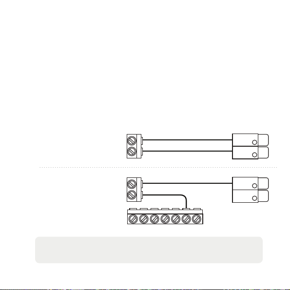
Accessory devices
The ecobee3 can control an accessory HVAC device like a
humidifier, dehumidifier, or ventilation device from its ACC
terminals.
If you have 2 wires at the thermostat from the accessory,
then your accessory is externally powered. If you have only 1
wire then it is internally powered.
Option 1. Externally
powered wiring
Accessory device
24V
C
ecobee3 terminals
ACC+
ACC-
Option 2. Internally
powered wiring
24V
C
Y1 Y2 W1 W2 R C G
ACC+
ACC-
HVAC
control board
Note: You will need to configure the accessory device when you
first power on your ecobee3.
29
Page 30
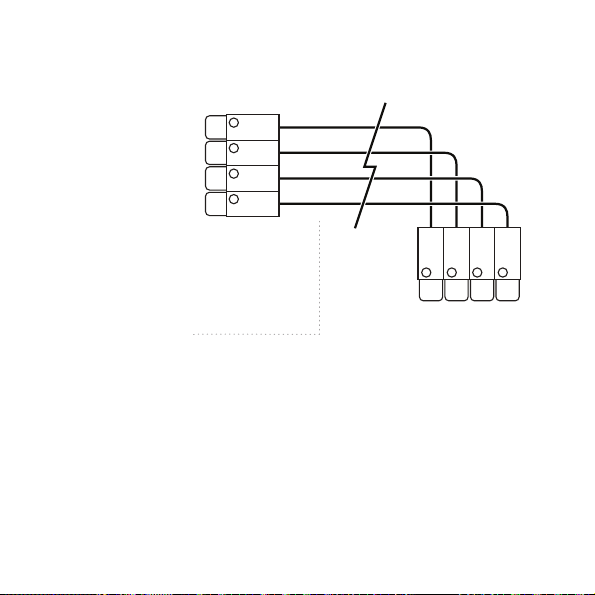
PEK thermostat wiring
The R wire needs
to go into the Rc
terminal on your
ecobee3
Wires coming out the
wall and connecting to
HVAC equipment
30
Rc
W1
(AUX1)
G
Y1
R G Y W
Page 31

Approvals
This product was designed and built in accordance to RoHS directive
2002/95/EC and contains no hazardous substances as defined by this
directive.
FCC Compliance Statement
This equipment has been tested and found to comply with the limits for
Class B digital devices, pursuant to Part 15 of the FCC Rules. These limits
are designed to provide reasonable protection against harmful interference
in a residential installation. This equipment generates, uses, and can radiate
radio frequency energy and, if not installed and used in accordance with the
instruction manual, may cause harmful interference to radio communications.
However, there is no guarantee that interference will not occur in a particular
installation. If this equipment does cause harmful interference to radio or
television reception, which can be determined by turning the equipment o
and on, the user is encouraged to try to correct the interference by one or
more of the following measures:
- Reorient or relocate the receiving antenna.
- Increase the separation between the equipment and receiver.
- Connect the equipment to an outlet on a dierent circuit from the receiver.
- Consult the dealer or an experienced radio/TV contractor for help.
To satisfy FCC/IC RF exposure safety requirements, a separation distance
of 8 inches (20 cm) or more should be maintained between this device and
persons. To ensure compliance, operation at closer than this distance is not
allowed.
31
Page 32

FCC ID: WR9EBSTATZBE3 IC: 7981A-EBSTATZBE3
Warning: Changes or modifications not expressly approved by ecobee Inc.
could void the user’s authority to operate the equipment.
3-Year Limited Warranty
ecobee warrants that for a period of three (3) years from the date of purchase
by the consumer (“Customer”), the ecobee3 (the “Product”) shall be free
of defects in materials and workmanship under normal use and service.
During the warranty period, ecobee shall, at its option, repair or replace any
defective Products, at no charge. Any replacement and/or repaired device
are warranted for the remainder of the original warranty or ninety (90) days,
whichever is longer.
If the product is defective, call Customer Service at 1-877-932-6233. ecobee
will make the determination whether a replacement product can be sent to
you or whether the product should be returned to the following address:
ecobee Customer Service, 477 Richmond St West, Suite 210, Toronto, Ontario,
M5V 3E7, Canada. In the event of a failure of a Product, Customer may:
(a) if Customer did not purchase the Product directly from ecobee, contact
the third party contractor from whom the Product was purchased to obtain an
equivalent replacement product, provided the contractor determines that the
returned Product is defective and Customer is otherwise eligible to receive a
replacement product;
(b) contact ecobee directly for service assistance at 1-877-932-6233
and ecobee will make the determination whether an advance equivalent
replacement Product can be sent to Customer with return shipping supplies
(in which case a hold shall be put on Customer’s credit card for the value of
the replacement Product until ecobee has received the defective Product).
Product should be returned to the following address: ecobee Customer
32
Page 33

Service, 477 Richmond St West, Suite 210, Toronto, Ontario, M5V 3E7, Canada.
If the returned Product is found by ecobee to be defective and Customer
is otherwise eligible to receive a replacement product, no amount shall be
charged to Customer’s credit card; or
(c) ship the defective Product directly to ecobee, in which case Customer shall
contact ecobee directly at 1-877-932-6233, so ecobee can make the required
shipping arrangements. Upon receipt of the defective Product, ecobee will
ship an equivalent replacement product to Customer, provided the returned
Product is found by ecobee to be defective and Customer is otherwise eligible
to receive a replacement product.
This warranty does not cover removal or reinstallation costs and shall not
apply if the damages were found to be caused by something other than
defects in materials or workmanship, including without limitation, if the
Product:
- was operated/stored in abnormal use or maintenance conditions;
- is repaired, modified or altered, unless ecobee expressly authorizes such
repair, modification or alteration in writing;
- was subject to abuse, neglect, electrical fault, improper handling, accident or
acts of nature;
- was not installed by a licensed Heating Ventilating and Air Conditioning
(HVAC) contractor; or
- was installed improperly.
ecobee’s sole responsibility shall be to repair or replace the Product within
the terms stated above. ECOBEE SHALL NOT BE LIABLE FOR ANY LOSS
OR DAMAGE OF ANY KIND, INCLUDING ANY SPECIAL, INCIDENTAL OR
CONSEQUENTIAL DAMAGES RESULTING, DIRECTLY OR INDIRECTLY, FROM
ANY BREACH OF ANY WARRANTY, EXPRESS OR IMPLIED, OR ANY OTHER
FAILURE OF THIS PRODUCT. Some US states and Canadian provinces do not
33
Page 34

allow the exclusion or limitation of incidental or consequential damages, so
the above limitation or exclusion may not apply to you.
ecobee’s responsibility for malfunctions and defects in materials and
workmanship is limited to repair and replacement as set forth in this warranty
statement. All express and implied warranties for the product, including but
not limited to any implied warranties and conditions of merchantability and
fitness for a particular purpose, are limited to the three-year duration of this
limited warranty. No warranties, whether expressed or implied, will apply
after the limited warranty period has expired. Some US states and Canadian
provinces do not allow limitations on how long an implied warranty lasts, so
this limitation may not apply.
ecobee neither assumes responsibility for nor authorizes any other person
purporting to act on its behalf to modify or to change this warranty, nor to
assume for it any other warranty or liability concerning this product.
This warranty gives you specific rights, and you may also have other rights
which vary from jurisdiction to jurisdiction. If you have any questions
regarding this warranty, please write to ecobee Customer Service, 477
Richmond St West, Suite 210, Toronto, Ontario, M5V 3E7, Canada.
34
Page 35

Page 36

We’re here to help
ecobee.com | [email protected] | 1.877.932.6233
© 2014 ecobee Inc. All rights reserved. ecobee and the ecobee logo are
trademarks of ecobee Inc., registered in the U.S. and other countries.
Printed in China
EB-STATe3-01
 Loading...