

Page 1

0432 - CPD - 0031
ECO Schulte GmbH & Co. KG
Iserlohner Landstraße 89
D-58706 Menden
EN 1154:1996+A1:2002
3
8 1-4 31 1
2-5 41 1
3
8
5-6 41 1
3
8
06
0432 - CPD - 0143
0432 - CPD - 0147
ECO Schulte GmbH & Co. KG
Iserlohner Landstraße 89
D-58706 Menden
EN 1155:1997+A1:2002
EN 1158:1997+A1:2002
06
3-5 01 13 8
G
S
schließen
2
3
4
5
5
6
1
2
3
4
Max. Türbreite
Max. door width
Largeur de porte max.
850 mm
950 mm
1100 mm
1250 mm
Max. Türbreite
Max. door width
Largeur de porte max.
1250 mm
1400 mm
Max. Türbreite
Max. door width
Largeur de porte max.
750 mm -7
850 mm
950 mm 0
1100 mm
Umdrehungen
Rotations
Rotations
-5
0
+7
+15
Umdrehungen
Rotations
Rotations
0
+6
Umdrehungen
Rotations
Rotations
-4
+6
Türschließergröße
Door closer size
Force de ferme porte
TS-61 G
EN 2-5
Türschließergröße
Door closer size
Force de ferme porte
TS-61 G
EN 5-6
Tür
Türschließergröße
Door closer size
Force de ferme porte
TS-51 G
EN 1-4
DIN links - spiegelbildlich
DIN left - mirror image
DIN gauche - inverser l´illustration
Abkürzungen
SG
geschwindigkeit
ES
ÖD
Schließkraft
SK
Schließ-
Endschlag
Öffnungsdämpfung
Abbrevations Abrévations
Closing speed
CS
Latching speed
LS
BC
CF
Back check
Closing force
VF
CF
FO
FF
Vitesse de
fermeture
Coup final
Frein á
l’ouverture
Force de
fermeture
Für die Montage dürfen ausschließlich Originalteile des Herstellers verwendet werden. Die Montagearbeiten müssen gemäß Anleitung von
einer qualifizierten Person durchgeführt werden. Bei Nichtbeachtung entfällt jeglicher Garantieanspruch. Diese Anleitung ist vom Monteur
nach der Montage an den Betreiber weiterzugeben!
Only original parts have to be used. The assembly has to be made by a qualified person according to the mounting instruction. In case of
non-respect the guarantee is invalid. This instruction is to be handed over to the operator by the fitter after assembly!
Impérativement utiliser la notice de montage fournie par le fabricant. La mise en œuvre et le montage doivent être exécutés par du personnel qualifié. Le non respect de ces règles annule catégoriquement tout droit de garantie Cette instruction est à remettre par le poseur
à l’exploitant après montage.
Leistungserklärung nach Verordnung (EU) Nr. 305/2011 finden Sie unter http://www.eco-schulte.de/leistungserklaerungen
Declaration of performance according to Regulation (EU) No 305/2011 see http://www.eco-schulte.de/declarationofperformance
Déclaration des performances conformément au règlement (UE) N° 305/2011 voir http://www.eco-schulte.de/declarationdesperformances
1/17
Page 2

1a
Direktmontage (ohne Unterprofil)
Direct mounting (without underprofile)
Montage direct (sans sous profil)
13
53
16
Bohrung für elektrischen
Anschluss (24 V DC)
Drilling for electrical
connection (24 V DC)
Alésage pour raccordement
électrique (24 V DC)
X = 55-92mm
X
120
122
27
Ø
12
160
258
23
546
16
G
446
60,5
13
13
59,5
A
46
53
18
A
53
22,5
S
160
16
122
2/17
Page 3

1b
Montage mit Adaptionsprofil
Mounting with adaptor plate
Montage avec profil d’adaptation
26
53
16
Bohrung für elektrischen
Anschluss (24 V DC)
Drilling for electrical
connection (24 V DC)
Alésage pour raccordement
électrique (24 V DC)
(optional, optional, optionnelle)
X = 55-92mm
X
120
130
122
258
Ø
160
546
2
1
37
26
26
446
60,5
59,5
A
46
53
16
G
18
A
53
22,5
S
160
16
122
3/17
Page 4

1c
Montage mit Sturzfutterwinkel
Mounting with under-lintle angle
Montage sous linteau avec équerre
95
(optional, optional, optionnelle)
X = 60-92mm
717
X
16
Bohrung für elektrischen
Anschluss (24 V DC)
Drilling for electrical
connection (24 V DC)
Alésage pour raccordement
180
94,5
20
77
122
205
160
électrique (24 V DC)
2
1
Ø
146
16
667
95
146
205
18
46
60
582
261
95
<
33
90,5
17
24
261
60
60,5
A
160
16
122
G
A
64,5
S
4/17
Page 5

3a
2
3
2
1
4
2
2
1
1
5/17
Page 6

5a
Direktmontage (ohne Unterprofil)
Direct mounting (without underprofile)
Montage direct (sans sous profil)
24V DC
+15%/-10%
4,5x30
M5x20
5b
24V DC
+15%/-10%
2
4,5x30
M5x20
Montage mit Adaptionsprofil
Mounting with adaptor plate
Montage avec profil d’adaptation
5c
24V DC
+15%/-10%
1
1
1
2
1
2
4,5x30
M5x20
Montage mit Sturzfutterwinkel
Mounting with under-lintle angle
Montage sous linteau avec équerre
2
6/17
Page 7
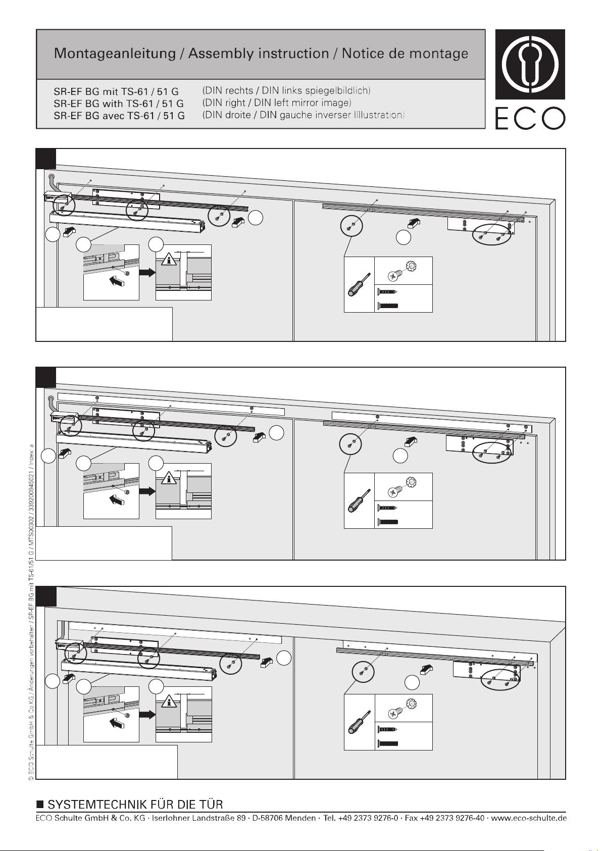
6a
1
2
3
4
13mm
1
6x
Direktmontage (ohne Unterprofil)
Direct mounting (without underprofile)
Montage direct (sans sous profil)
6b
2
Montage mit Adaptionsprofil
Mounting with adaptor plate
Montage avec profil d’adaptation
3
6x
4
4,5x30
M5x20
1
1
13mm
4,5x30
M5x20
6c
2
Montage mit Sturzfutterwinkel
Mounting with under-lintle angle
Montage sous linteau avec équerre
3
6x
4
13mm
1
1
4,5x30
M5x20
7/17
Page 8
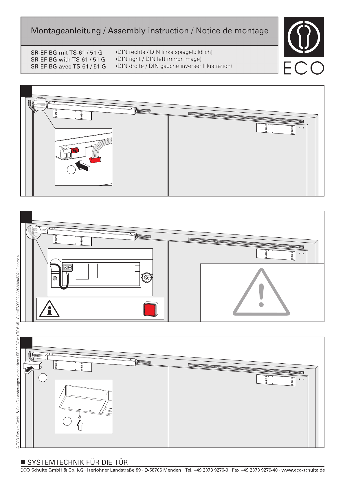
7
1
8
24 V DC +15% / -10%
Die elektrischen Anschlüsse müssen gemäß Anleitung von einer qualifizierten
Person durchgeführt werden. Bei Nichtbeachtung entfällt jeglicher
Garantieanspruch. Diese Anleitung ist vom Monteur nach der Montage an
den Betreiber weiterzugeben!
The electrical installation has to be made by a qualified person according to
the mounting instruction. In case of non-respect the guarantee is invalid. This
instruction is to be handed over to the operator by the fitter after assembly!
Handtaster setzen!
Install a manual button!
Installez un bouton poussoir!
Tür
schließen
La mise en œuvre,la connection électrique et le montage doivent être
exécutés par du personnel qualifié. Le non respect de ces règles annule
catégoriquement tout droit de garantie. Cette instruction est à remettre par le
poseur à l’exploitant après montage.
9
1
2
8/17
Page 9
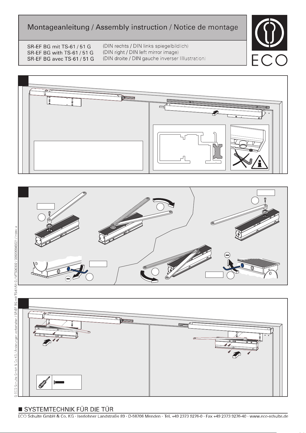
10
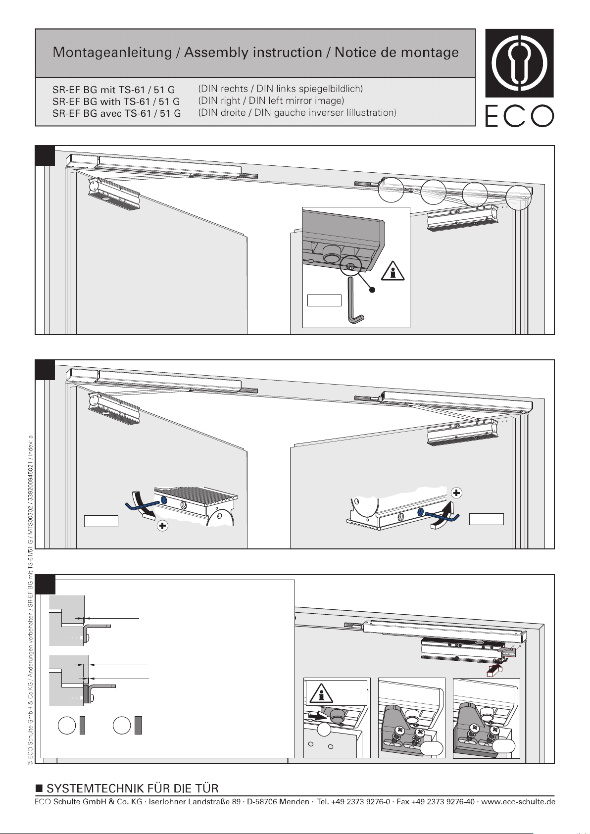
Madenschrauben der Standflügelgleitschiene noch nicht
festziehen.
Do not yet tighten the screws of the passive leaf slide rail.
Ne pas visser les vis six pans de la glissère du vantail
secondaire.
11
12
M6x20
1
SW 2,5
2
M6x20
1
3
3
SW 2,5
2
M5x40
9/17
Page 10
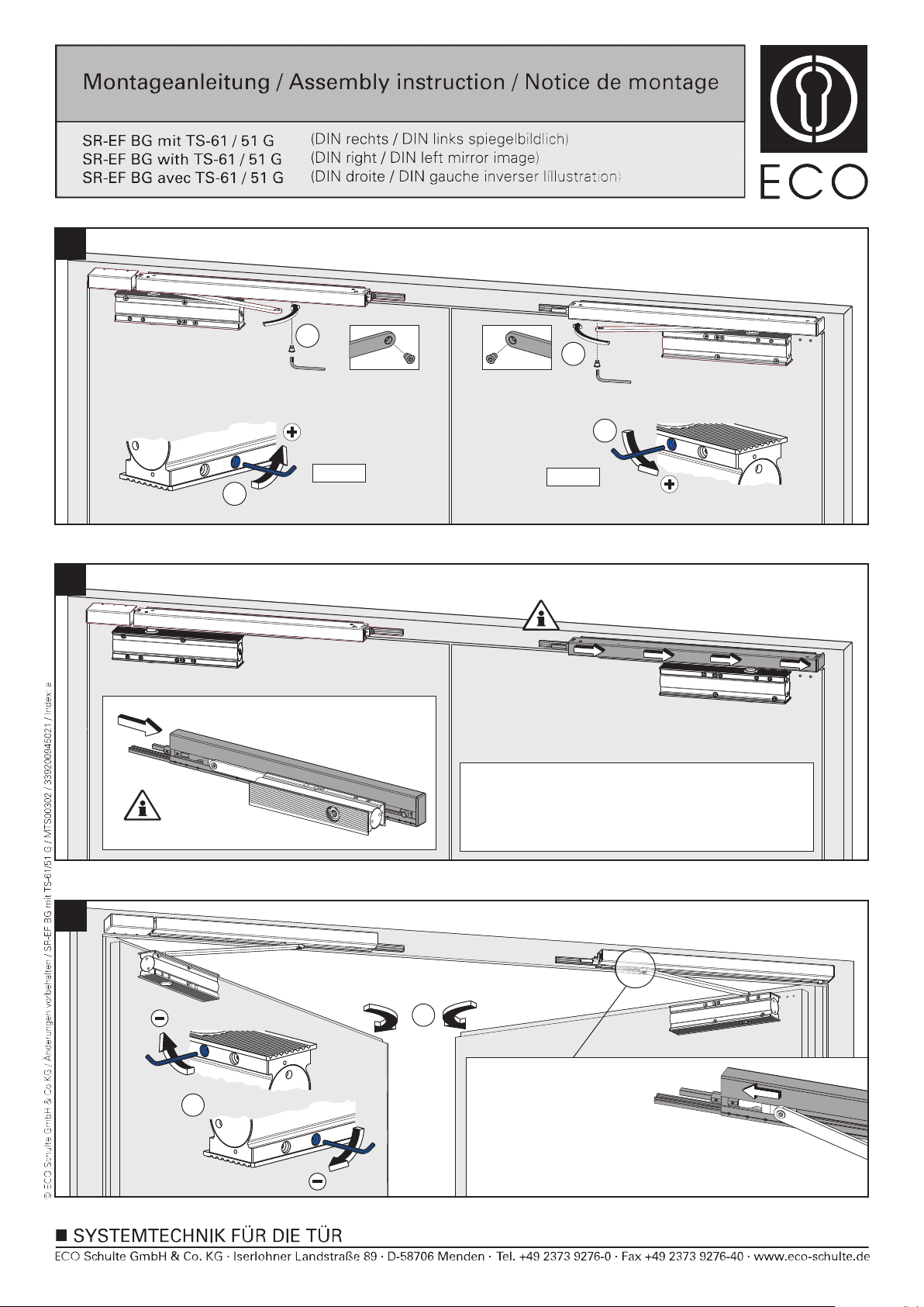
13
2
2
14
2
SW 2,5
SW 2,5
1
2
1
Standflügelgleitschiene auf Anschlag in Richtung Gleitschuh
schieben.
Move slide rail of passive leaf towards the maximum direction
of the sliding block.
Glisser la glissière du vantail secondaire en butée vers le patin.
15
2
Durch Öffnen des Standflügels
auf ca. 40° wird die Gleitschiene
1
in die endgültige
Montageposition geschoben.
By opening the passive leaf to approximately
40°, the slide rail will be moved into the final
mounting position.
Lors de lóuverture à 40° la glissière du vantail
secondaire atteindra sa position finale.
10/17
Page 11
16
17
SW 2,5
SW 2,5
8x
2
2
SW 2,5
18
A
4mm
Xmax 2mm
Ymax 8mm
Xmax 2mm
+
B
8mm
Der maximale Zargenüberstand
beträgt 2mm, darüber sind die
Distanzplatten A oder B zu
verwenden. Der maximale
Zargenüberstand mit Platten beträgt
8mm, darüber bitte Anfragen.
Maximum projection length of door
frame is 2mm, otherwise use
distance plates A or B. The
maximum projection lenght of door
frame with distance plates is 8mm,
all other lenghts on request.
Recouvrement maximum 2mm, si
plus utiliser les cales A (4mm) ou B
(8mm). Au-delà de 8mm de
recouvrement, nous consulter.
1
max.
2.1
2.2
11/17
Page 12
19
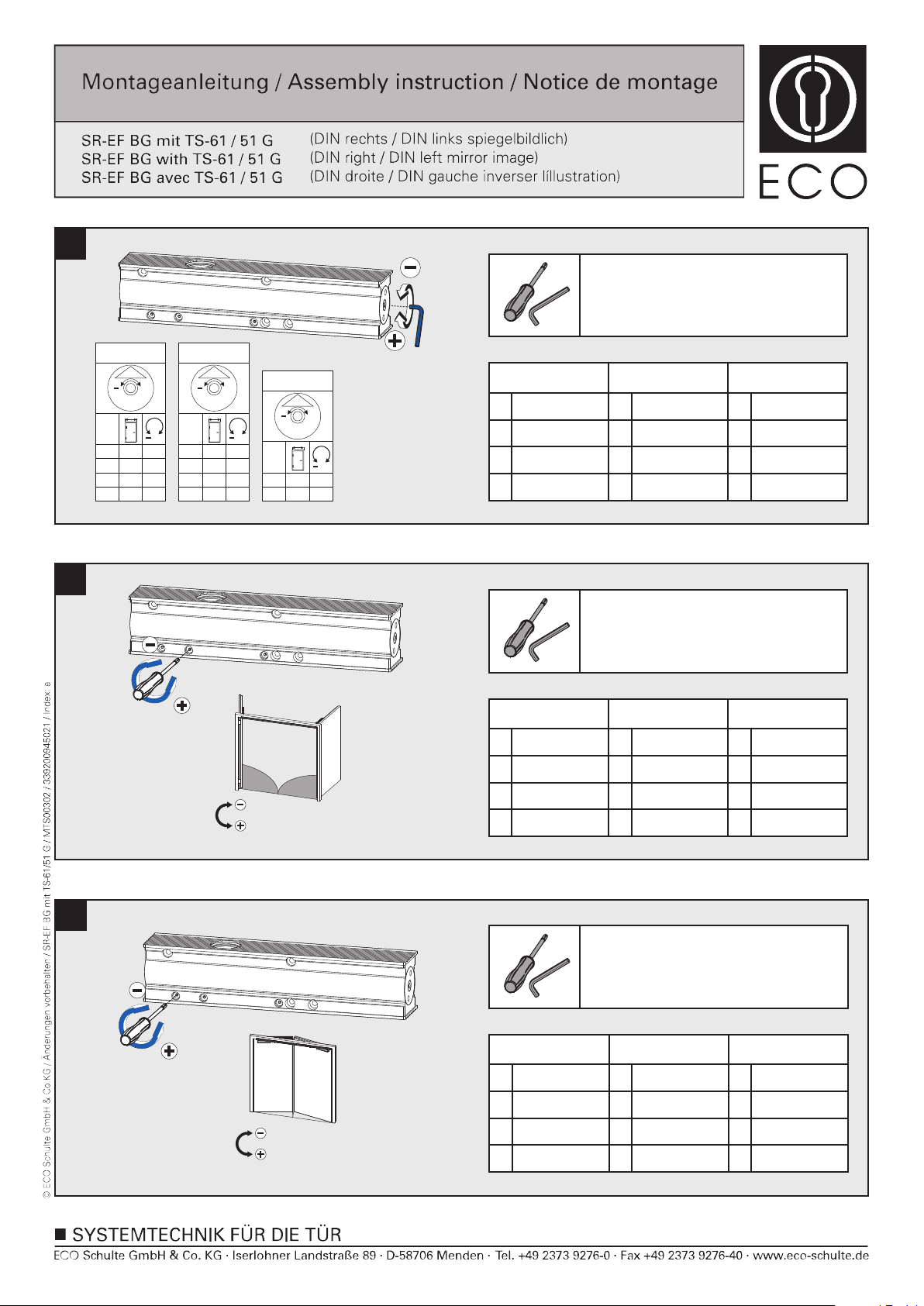
Einstellungen Türschließer
Adjustments of the door closer
Reglages du ferme - portes
20
TS-51 G
1
EN
1
2
3
4
3
mm
750
850
950
1100
TS-61 G
3
EN
+
5
2
mm
850
2
3
950
4
1100
5
+15
1250
+
4
+
-7
-4
0
+6
TS-61 G
5
+
6
5
+
-5
0
+7
EN
mm
+
0
1250
5
+6
6
1400
SK/CF/FF
Abkürzungen
Schließkraft
SK
SG
geschwindigkeit
ES
ÖD
Schließ-
Endschlag
Öffnungsdämpfung
Abbrevations Abrévations
Closing force
CF
Closing speed
CS
Latching speed
LS
BC
Back check
FF
VF
CF
FO
Force de
fermeture
Vitesse de
fermeture
Coup final
Frein á
l’ouverture
Einstellungen Türschließer
1
2
ca.95°-0°
G
2
3
S
SG/CS/VF
ca.95°-0°
Abkürzungen
Schließkraft
SK
SG
geschwindigkeit
ES
ÖD
Schließ-
Endschlag
Öffnungsdämpfung
Adjustments of the door closer
Reglages du ferme - portes
Abbrevations Abrévations
Closing force
CF
Closing speed
CS
Latching speed
LS
BC
Back check
FF
VF
CF
FO
Force de
fermeture
Vitesse de
fermeture
Coup final
Frein á
l’ouverture
21
Einstellungen Türschließer
1
2
3
ES/LS/CF
1
10°-0°
Abkürzungen
Schließkraft
SK
SG
geschwindigkeit
ES
ÖD
Schließ-
Endschlag
Öffnungsdämpfung
Adjustments of the door closer
Reglages du ferme - portes
Abbrevations Abrévations
Closing force
CF
Closing speed
CS
Latching speed
LS
BC
Back check
FF
VF
CF
FO
Force de
fermeture
Vitesse de
fermeture
Coup final
Frein á
l’ouverture
12/17
Page 13
22
23
70°-ca.95°
1
G
G
3
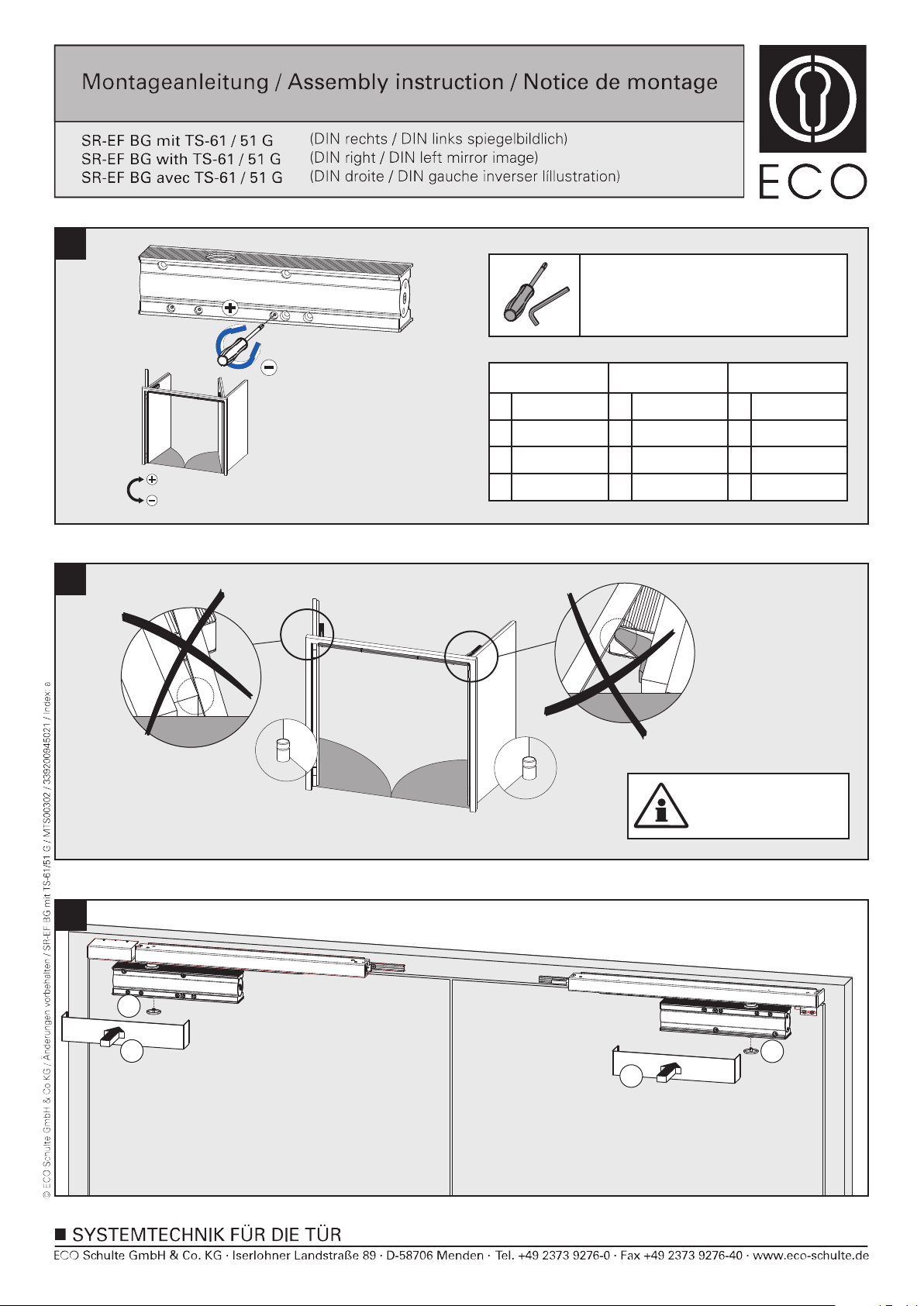
ÖD/BC/FO
2
S
3
70°-ca.95°
Abkürzungen
Schließkraft
SK
SG
geschwindigkeit
ES
ÖD
Schließ-
Endschlag
Öffnungsdämpfung
Einstellungen Türschließer
Adjustments of the door closer
Reglages du ferme - portes
Abbrevations Abrévations
Closing force
CF
Closing speed
CS
Latching speed
LS
BC
Back check
FF
VF
CF
FO
Force de
fermeture
Vitesse de
fermeture
Coup final
Frein á
l’ouverture
24
ca.95°
G
S
ca.95°
Türstopper setzen
Place door stopper
Placer butoir de porte
2
1
2
1
13/17
Page 14
25
26
X
1
X - 1mm
2
3
27
1
SW2,5
2
90°
SW2,5
14/17
Page 15
2a28
29
G
G
60°
Funktionsprüfung SR
Beide Türen ca. 60° öffnen, Gangflügel (G) muss geöffnet
bleiben. Standflügel (S) schließt. Gangflügel (G) darf erst ab
1
S
60°
3
S
2
30°
einem Schließwinkel des Standflügels (S) von ca. 30°
schließen.
Functionality test SR
Open both doors approx. 60°, active leaf (G) has to remain
open. Passive leaf (S) closes. Active leaf (G) is only allowed to
close if the passive leaf (S) reaches a closing angle of approx.
30°.
Test du sélecteur SR
Ouvrir les deux vantaux à 60°, le vantail principal (G) doit se
maintenir en position ouverte. Le vantail secondaire (S) doit se
fermer. Le vantail principal (G) doit se fermer à partir d’un angle
de fermeture du vantail secondaire (S) à partir de 30°.
30
Click
Click
Y
15/17
Page 16
31
32
2
Y - 8mm
1
33
16/17
Page 17
34
35
SW 2,5
95°(G)
95°(S)
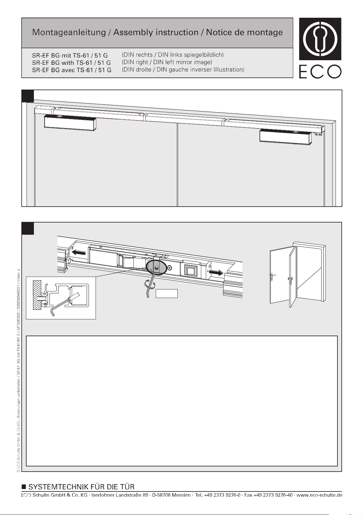
Die Feststellanlage ist für einen Türöffnungswinkel von 90° vormontiert. Der Öffnungswinkel lässt sich durch Verschieben der Feststelleinheit
in Richtung Türmitte bis auf 70° und Richtung Türbänder bis auf 95°(G), 95°(S) verstellen. Hierzu wird die Tür auf den gewünschten
Feststellwinkel geöffnet und festgesetzt. Zum Verschieben der Feststelleinheit muss die Klemmschraube gelöst werden. Die Feststelleinheit
dann auf Anschlag an das Gleitstück schieben und Klemmschraube anziehen. Beim max. Türöffnungswinkel kleiner 90° kann das Gleitstück
die Klemmschraube verdecken. In diesem Falle muss die Feststelleinheit vor dem Öffnen und Festsetzen der Tür auf Anschlag in Richtung
Türmitte nach Lösen der Klemmschraube verschoben werden. Klemmschraube wieder festziehen und wie vorher beschrieben den
gewünschten Feststellwinkel einstellen.
Funktionsprüfung der Feststellung durchführen!
The slide rail with hold-open function is premounted for a door opening angle of 90°. The open angle can be changed up to 70° by moving the
hold open unit in the direction of the door middle. It can also be changed up to 95°(G), 95°(S) by moving the hold open unit in the direction of
the door hinges. This is achieved by opening the door until the requested opening angle is achieved and fixing it in this position. In order to
move the hold open unit, you have to loosen the fixing screw. Move the hold-open unit till dead stop of the sliding block and tighten the fixing
screw. In case the max. door opening angle is smaller than 90°, the sliding block might cover the fixing screw. In this case, the hold-open unit
has to be moved till dead stop in direction of door middle after fixing screw has been loosened. This has to be done before the door is opened
and fixed in wished position. Tighten fixing screw and adjust (as described above) the requested hold-open angle.
Carry out a functionality test of hold-open function.
Le sélecteur de fermeture est pré-disposé pour un angle d’ouverture de 90°. Cet angle peut être modifié en dévissant les vis pointeaux et en
déplacant l’arrêt de 70 à 95°(G), 95°(S). De cette façon la porte peut être maintenue à l’angle d’ouverture souhaité.
Tester le fonctionnement.
70°
17/17
 Loading...