

TFC Group LLP, Tower House,
Vale Rise, Tonbridge, Kent TN9 1TB
http://www.tfc-group.co.uk
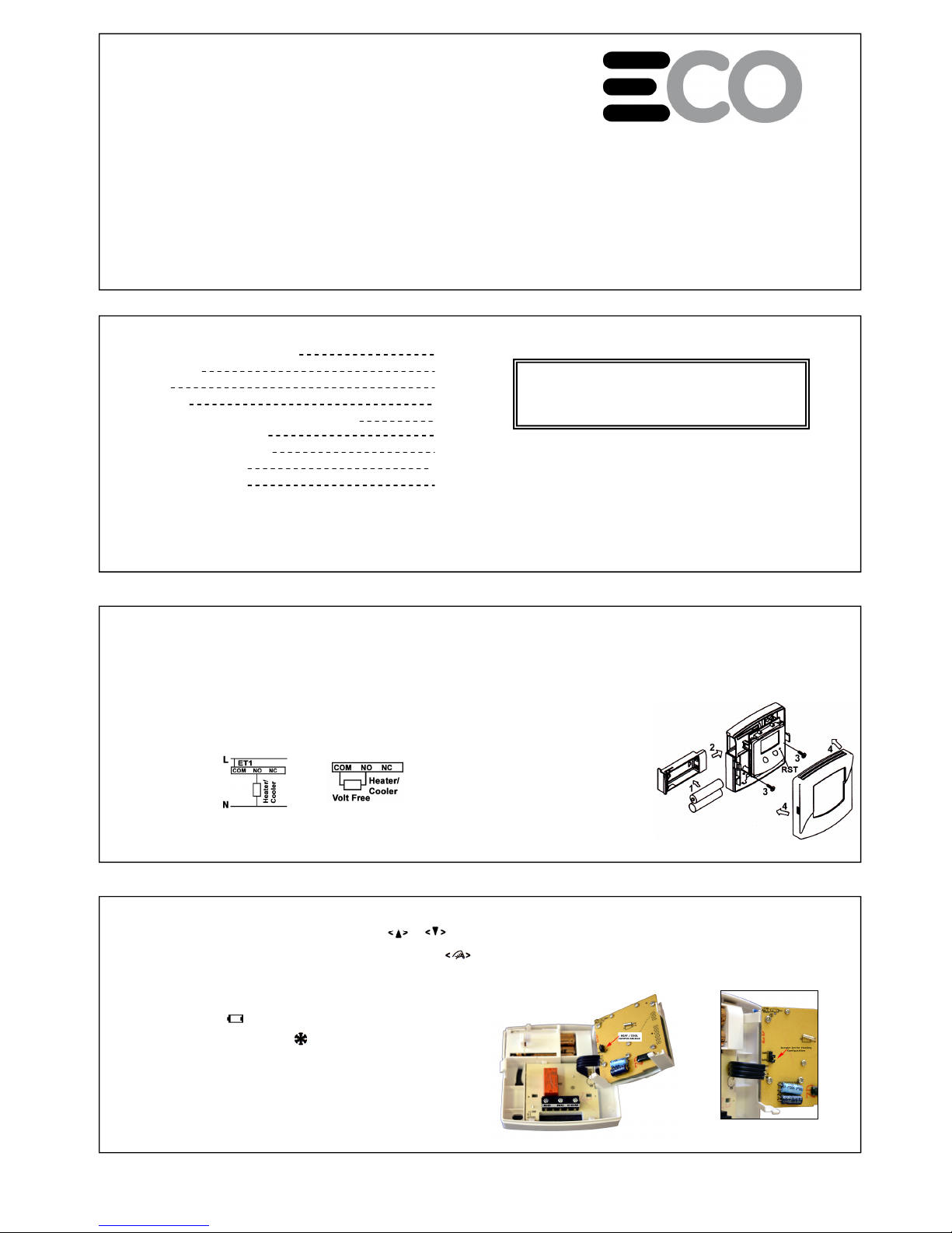
ET1
Digital Electronic Thermostat
INSTRUCTION MANUAL
ET 1 LCD Electronic Thermostat
A, Installation & Mounting:
1, Installation Location:
The thermostat should be mounted on an inner wall 1.5m above the floor in
a position where it is readily affected by changes in the ambient room
temperature. Prevent direct exposure sunlight and moisture. Do not place
this unit where air circulation is low, or where it is susceptib le to rapid
temperature changes (e.g. near a door or window). Do not position near
heating/cooling appliances.
2
Caution:
Turn off the ET1 and any electrical devices that are to be
connected after installation. The installation must be carried
out by a qualified electrician and conform to current IEE
regulations.
B, Battery installation / Replacement:
Caution: Turn off electrical devices and disconnect the supply to any
connected appliances before installing or replacing batteries. Replace only
with the same (AAA Alkaline) or equival ent batteries. Do not dispose of used
batteries with household waste. Refer to your local area for correct disposal
method.
1, Pull out the battery draw.
2, Place new batteries taking note of
orientation of +/- on battery drawer.
3, Dispose old batteries properly.
4, Slide battery draw into position.
5, Check operation and press reset
(RST) if not functioning correctly.
4
(Figure 1)
C, Setting Temperature:
- Adjust the temperature to your chosen set-point using the or
buttons.
- Ambient room temperature display will resume af ter 8 seconds and the
icon will disappear.
D, Default Display Mode:
- Temperature detection starts and LCD displays the room temperature.
- If the battery is LOW, will be displayed. The batteries must be
replaced immediately.
- The defrost function is activated with displayed when the temperature
is 50C or below. The output will switch ON automatically for heating &
OFF if the ET1 is configured for cooling.
- If the ambient temperature falls below 00C the ET1 will display “LO”.
- Above 40.50C the ET1 will display “HI”.
5
E. Jumper Selection:
- Heating, Cooling Jumper Bridge.
When the jumper bridge is connected to “Heater” the heating
configuration is selected. When the jumper bridge is connected to
“Cooling” the cooling configuration is sele cted. The thermostat will not
operate without a jumper connection existing.
6
2, Wiring:
There are three terminals at the bottom of the ET1, labelled as
“Com” (Common), “NO” (normally open) and “NC” (normally closed).
Connect the appliance to the “NO” and “Com” terminals. Leaving the “NC”
terminal empty.
• Refer to the circuit diagram printed on rating label on the back of the
product.
• Push all wiring into wall prior to mounting to avoid trapping wires.
• The thermostat should be protected by the fused spur supplying the
heating system, using a fuse with a current rating no larger than 5A.
3, Mounting:
Mount the ET1 using the screw accessories provided through slots/holes on
rear face of the unit.
3
Mains
Switching
2
2
3
3
4
5
5
6
7
TABLE OF CONTENTS
A. Installation and mounting
1, Installation
2, Wiring
3, Mounting
B, Battery Installation / Replacement
C, Setting Temperature
D, Default Display Mode
E, Jumper Selection
F, Normal Operation
1
Page
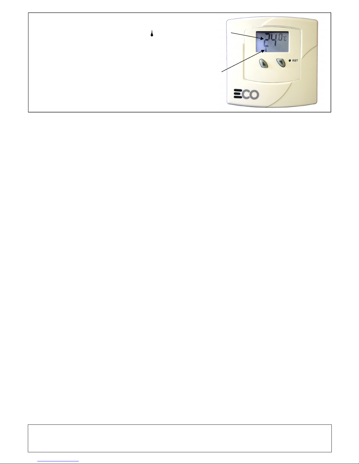
F, Normal Operation:
In the default run mode the ambient room
temperature is displayed. The Heating Indicator will
flash continuously when heating is called for (in
demand) and will not flash when the heating is no
longer required (Satisfied)..
7
Heating
Indicator
Ambient Room
Temperature
TFC Group LLP, Tower House, Vale Rise, Tonbridge, Kent TN9 1TB
tel: 01732 351680 email: sales@tfc.uk.com web:tfc-group.co.uk
 Loading...