

Page 1
CONSUL+
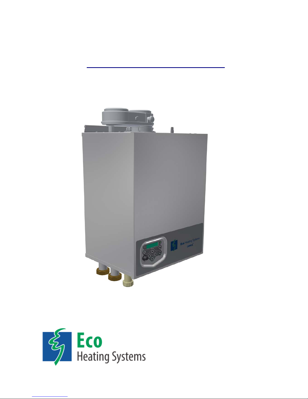
Wall hung high efficiency water heater
Installation, user and service instructions
BASE VERSION
E93.0901EN.A
Models:
• Consul+35
• Consul+55
Page 2

Page 3

E93.0901EN.A Manual Consul+
3
TABLE OF CONTENTS
INTRODUCTION ……………………….………………………............................................................................6
SAFETY GUIDELINES ..................................................................................................................................... 6
1.1 IMPORTANT TECHNICAL WARNINGS AND GUIDELINES ................................................................................ 7
1.2 SAFETY VALVE ....................................................................................................................................... 9
TECHNICAL DATA CONSUL+ WATER HEATERS ...................................................................................... 10
2.1 FUNCTIONAL INTRODUCTION ................................................................................................................ 10
2.2 TABLE TECHNICAL SPECIFICATIONS ....................................................................................................... 11
2.3 TABLE TECHNICAL SPECIFICATIONS ERP .............................................................................................. 12
2.4 ERP SPECIFICATIONS ECOHS WATER TANKS. ........................................................................................ 12
DIMENSIONS .................................................................................................................................................. 13
3.1 WATER HEATERS CONSUL+ 35 .......................................................................................................... 13
3.2 WATER HEATERS CONSUL+ 55 .......................................................................................................... 14
3.3 TANK EWD150 – EWD230 - EWD300 - EWD450 - EWD750 ............................................................. 15
ACCESSORIES AND UNPACKING ............................................................................................................... 18
4.1 UNPACKING ......................................................................................................................................... 18
4.2 ACCESSORIES ..................................................................................................................................... 18
4.3 FLUE GAS AND AIR SUPPLY PARTS ........................................................................................................ 19
INSTALLATION OF THE CONSUL+ .............................................................................................................. 20
5.1 GENERAL NOTES ................................................................................................................................. 20
5.2 MOUNTING THE WATER HEATER AND TANK ............................................................................................ 21
5.2.1 Water heater mounting .................................................................................................................. 21
5.2.2 Tank positioning............................................................................................................................. 21
FLUE GAS AND AIR SUPPLY SYSTEM ....................................................................................................... 22
6.1 GENERAL ............................................................................................................................................ 22
6.2 TYPE OF FLUE GAS SYSTEMS. ............................................................................................................... 23
6.3 C63 CERTIFIED .................................................................................................................................... 24
6.4 AIR SUPPLY ......................................................................................................................................... 25
6.4.1 Combustion air quality ................................................................................................................... 25
6.4.2 Air supply through humid areas ..................................................................................................... 25
6.5 HEIGHTS ABOVE THE ROOF. ................................................................................................................. 26
6.6 FLUE GAS AND AIR SUPPLY RESISTANCE TABLE. ..................................................................................... 27
6.6.1 Flue gas and air supply resistance table ....................................................................................... 27
6.6.2 Six typical examples ...................................................................................................................... 28
6.6.3 Example A: Twin pipe system (C63). ............................................................................................ 28
6.6.4 Example B: Twin pipe system with separate pipes and concentric roof terminal (C33). .............. 28
6.6.5 Ex. C: Single pipe for flue gas and air supply from water heater room. (B23, B23P) ................... 30
6.6.6 Ex. D: concentric pipe with roof outlet (C33). ................................................................................ 31
6.6.7 Ex. E: concentric system (wall outlet C13). .................................................................................. 31
6.6.8 Air supply and flue gas outlet at different pressure zones (C53) .................................................. 33
ELECTRICAL INSTALLATION ...................................................................................................................... 34
7.1 GENERAL ............................................................................................................................................ 34
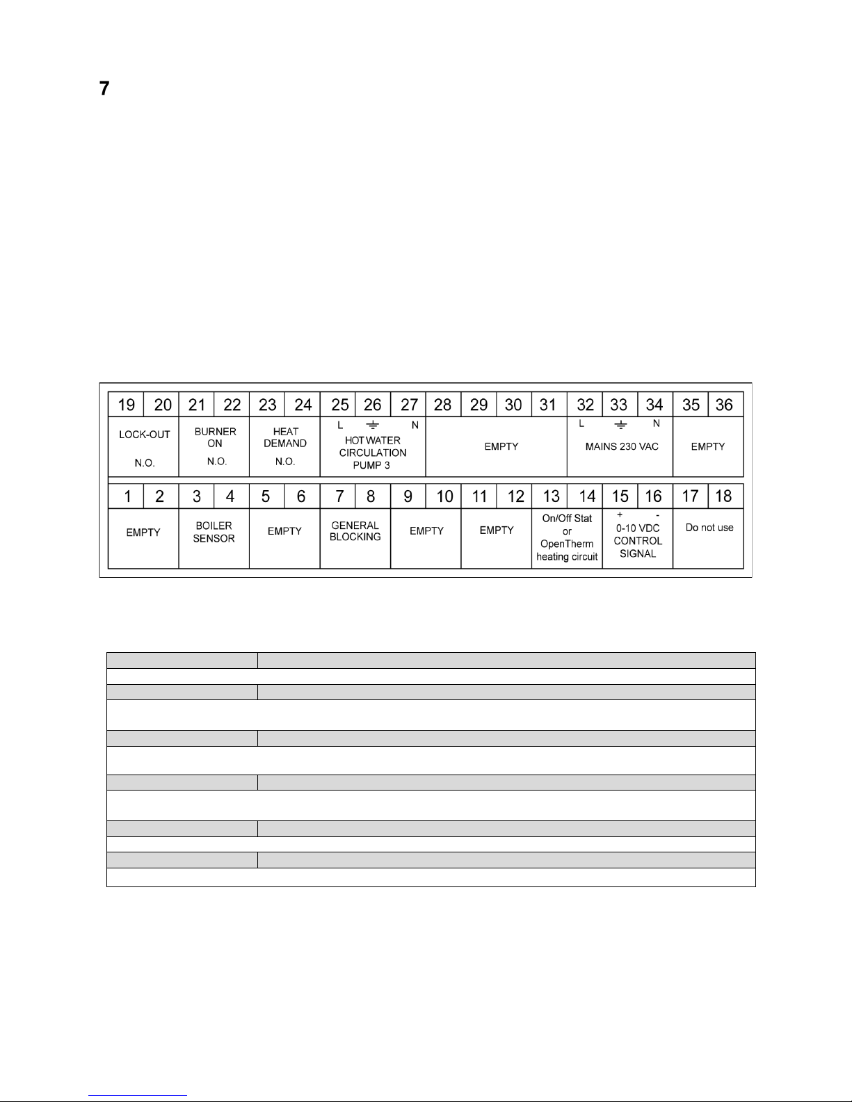
7.2 ELECTRICAL CONNECTIONS .................................................................................................................. 34
7.3 FUNCTION OF THE ELECTRICAL CONNECTIONS OF THE WATER HEATER ................................................... 34
7.4 SENSOR VALUES.................................................................................................................................. 35
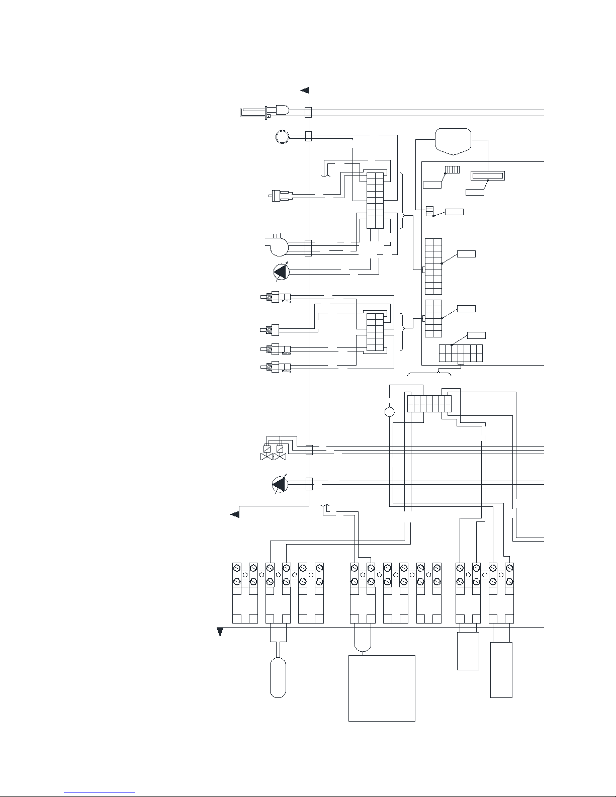
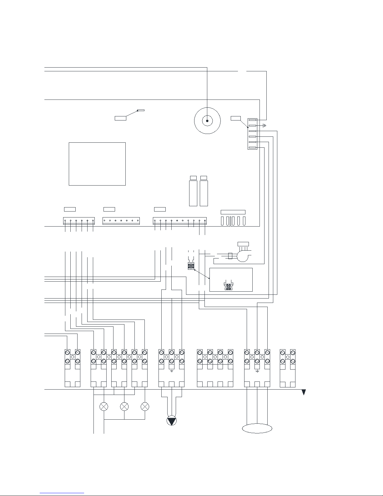
7.5 ELECTRICAL SCHEMATICS .................................................................................................................... 36
DE CONSUL+ WATER HEATER ................................................................................................................... 38
8.1 WATER QUAL ITY .................................................................................................................................. 38
8.2 FROST PROTECTION ............................................................................................................................ 38
8.3 LEGIONELLA PROGR AM ........................................................................................................................ 38
8.4 FLOW MONITORING .............................................................................................................................. 39
8.5 WATER PRESSURE SWITCH .................................................................................................................. 39
Page 4

E93.0901EN.A Manual Consul+
4
THE CONSUL+ SANITAIRY SYSTEM: INSTALLATION INSTRUCTIONS .................................................. 40
9.1 THE CONSUL+ SYSTEM ..................................................................................................................... 40
9.1.1 Stand-alone set-up ........................................................................................................................ 40
9.2 CONTROL ............................................................................................................................................ 41
9.2.1 Tank sensor ................................................................................................................................... 41
9.2.2 General control .............................................................................................................................. 41
9.3 WATER HEATER AND TANK: CONNECTIONS AND CONNECTION SIZES ........................................................ 42
9.3.1 Connecting the tank to the water heater ....................................................................................... 42
9.3.2 Connecting the tank to your DHW installation ............................................................................... 43
9.3.3 Condensate drain connection ........................................................................................................ 44
9.3.4 Pipe length and Diameters. ........................................................................................................... 45
USER INTERFACE ......................................................................................................................................... 46
10.1 CONTROL PANEL / DISPLAY UNI T ........................................................................................................... 46
10.2 CONTROL PANEL MENU STRUCTURE ..................................................................................................... 47
10.3 DISPLAY DURING OPERATION ................................................................................................................ 49
10.4 MONITOR SCREENS ............................................................................................................................. 50
10.5 SERVICE FUNCTION ............................................................................................................................. 52
10.6 SCHORNSTEINFEGER FUNCTION ........................................................................................................... 53
10.7 PROGRAMMING IN STANDBY MODE ........................................................................................................ 54
10.8 SETTING THE TIME & DATE ................................................................................................................... 54
10.9 SET POINTS ......................................................................................................................................... 55
10.10 SETTING THE TIMER PROGRAMS ........................................................................................................... 56
10.11 CHECKING THE OPERATING HISTORY .................................................................................................... 59
10.12 CHECKING THE FAULT HISTORY ............................................................................................................ 60
10.13 SETTING THE MAINTENANCE SPECIFICATIONS ........................................................................................ 61
10.14 SETTING THE USER LOCK ..................................................................................................................... 64
10.15 SETTING THE PARAMETERS AT THE CONTROL PANEL .............................................................................. 65
10.16 FAULT CODES DISPLAY ......................................................................................................................... 72
10.16.1 Lock-out codes ........................................................................................................................... 72
10.16.2 Blocking codes ............................................................................................................................ 73
10.16.3 Messages ................................................................................................................................... 75
CONTROLLING OPTIONS AND SETTINGS ................................................................................................. 76
11.1 GENERAL ............................................................................................................................................ 76
11.1.1 Max cooling time ......................................................................................................................... 76
11.1.2 temperature display on/off .......................................................................................................... 76
11.1.3 Gas type selection ...................................................................................................................... 76
11.1.4 Soft start option ........................................................................................................................... 77
11.1.5 Tank sensor sensitivity ............................................................................................................... 77
11.2 WATER HEATER OPTIONS ..................................................................................................................... 77
11.2.1 0-10 VDC remote flow temperature set point ............................................................................. 77
11.2.2 anti-Legionnaires’ disease (pasteurization) function .................................................................. 78
COMMISSIONING THE WATER HEATER .................................................................................................... 79
12.1 FIRST: FLUSHING THE WATER HEATER WITH WATER ............................................................................... 79
12.2 SECOND: FILLING & VENTING THE WATER HEATER AND THE SYSTEM ....................................................... 79
12.3 THIRD: CHECK THE WATER FLOW .......................................................................................................... 79
STARTING THE WATER HEATER ................................................................................................................ 81
13.1 GENERAL ............................................................................................................................................ 81
13.2 FIRING FOR THE FIRST TIME .................................................................................................................. 81
Page 5

E93.0901EN.A Manual Consul+
5
ADJUSTING AND SETTING THE BURNER .................................................................................................. 82
14.1 INTRODUCTION .................................................................................................................................... 82
14.1.1 Gas valve adjustment: tables ..................................................................................................... 82
14.1.2 adjustment values ....................................................................................................................... 83
14.1.3 Setting screws gas valve(s): drawings ....................................................................................... 84
14.1.4 Adjustment actions: general scheme .......................................................................................... 85
14.2 ADJUSTING IN CASE OF A NEW WATER HEATER, OR AFTER SERVICE (CASE A) .......................................... 85
14.2.1 General remark ........................................................................................................................... 85
14.2.2 Adjusting at maximum load ........................................................................................................ 85
14.2.3 Adjusting at minimum load ......................................................................................................... 85
14.3 ADJUSTING AFTER GAS VALVE REPLACEMENT, OR IN CASE OF GAS CONVERSION (CASE B) ....................... 86
14.3.1 General remarks ......................................................................................................................... 86
14.3.2 Adjusting at minimum load Consul+35 & Consul+55 ................................................................. 86
14.4 ADJUSTING PROCEDURES .................................................................................................................... 87
PUTTING THE WATER HEATER OUT OF OPERATION ............................................................................. 88
15.1 OUT OF OPERATION: ON/OFF FUNCTION ................................................................................................ 88
15.2 OUT OF OPERATION: POWER OFF .......................................................................................................... 88
FAULT CODES, BLOCKING CODES ............................................................................................................ 89
16.1 LOCK-OUT CODES ................................................................................................................................ 89
16.2 BLOCKING CODES ................................................................................................................................ 94
16.3 MAINTENANCE ATTEN TION FUNCTION .................................................................................................... 97
MAINTENANCE .............................................................................................................................................. 98
17.1 GENERAL ............................................................................................................................................ 98
17.2 INSPECTION & MAINTENANCE ............................................................................................................... 98
USER INSTRUCTIONS ................................................................................................................................. 101
INDEX ............................................................................................................................................................ 102
Page 6
E93.0901EN.A Manual Consul+
6
INTRODUCTION
This manual is written for:
The installer
The system design engineer
The service engineer
The user
abbreviations
EHS
NB
Eco Heating Systems Groningen B.V.
NOTICE
symbols
Warning: important information related to the safety
of persons and/or the appliance
terminology
Flow
Return
Water heater hot water out
Water heater cold water in
SAFETY GUIDELINES
Carefully read all these instructions before commencing installation.
Keep this manual near the water heater for quick reference.
The appliance should be installed by a skilled installer according to all applicable standards and regulations.
Failure to comply with these regulations could deem the warranty invalid.
Without written appr oval of the m anuf acturer the internals of the water heat er may not be chan ged. W hen thes e
changes are executed without approval, the water heater certification is invalid.
Commissioning, m aintenance and r epair m ust be done b y a skilled ins taller/en gineer, acc ording to a ll applic able
standards and regulations.
What to do if you smell gas:
Do NOT use any electrical equipment
Do NOT press any switches
Close the gas supply
Ventilate the room (open the windows and/or outside water heater room doors)
Immediately warn the installer.
The manufacturer/supplier is not liable for any damage caused by inaccurately following of these
mounting instructions. Only original parts may be used when carrying out any repair or service works.
This appliance is not intend ed for us e by persons (incl uding childr en) with red uced ph ysical, sensor y
or mental capabilities, or lack of experience and knowledge, unless they have been given supervision
or instruction concerning use of the appliance by a person responsible for their safety. Children should
be supervised to ensure that they do not play with the appliance.
Page 7
E93.0901EN.A Manual Consul+
7
1.1 Important technical warnings and guidelines
For FAULT CODES see Ch. 16 on page 82
T
he EHS Domestic Hot Water systems will, for a long period, com fortably m eet your requir ement of hot water of
the right temperature at th e right hour, prov ided that a few impor tant condit ions have b een fulf illed regardi ng the
installation.
Please follow all instr uctions and recomm endations presente d in this manual b y EHS, especia lly the ones concerning the next important topics:
- Water quality (also see § 8.1 on page 32)
A first necessar y condition is the qual ity of the water t o be heated in the D HW water heater. Thr ee values
matter: hardness, total amount of dissolved solids and acidity. If water quality does NOT meet the requirements
the system may be seriously damaged in time!
♦ Hardness should not exceed 205 PPM CaCO
3
(11,5°dH)
♦ TDS (Total Dissolved Solids) should not exceed 450 PPM
♦ Hardness and TDS together may not exceed 450 PPM
♦ pH value should be between 6,5 and 7,5, measured cold
The actual values can be retrieved at your local water supplier.
I
f water quality doesn’t meet the abovem entioned requir ements, a water tr eatment installat ion should be in-
stalled to improve water quality to the required levels, if possible.
- Water flow velocity and pump
Always use the suppl ied pump f or this heater, th e software a nd param eters are specially set f or this t ype of
pump. All specifications and settings in this manual also refer to this specific pump.
The maximum water flow velocity must be lower as 1 m/sec when using copper pipes.
- Cascading.
We advise NOT to casc ade heaters and/or tanks because d ifferent pum ps and pipe diam eters are needed,
please use the CD heater instead.
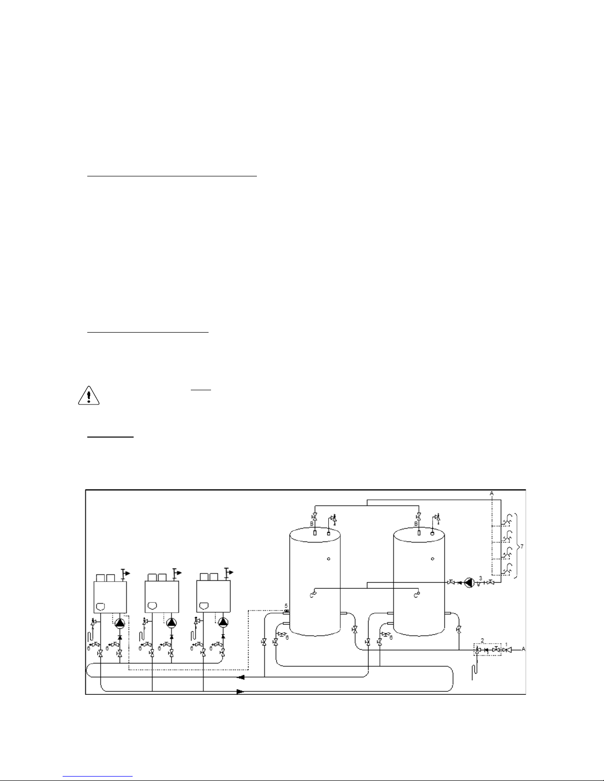
Should for any reason cascading still be needed, please contact your supplier. Connect all water heaters and
tanks according to the scheme below (Tichelmann system).
Following the instructions and recommendations given in the referred paragraphs will highly improve the functioning and considerably lengthen the life time of your DHW system.
The applied pump must be controlled b y t he Consul+ water he ater c ontrol o nl y. If, for any reason, an
external pump control is applied with out written appr oval of EHS, t hen the com plete warrant y on the
Consul+ water heater and all delivered parts will become invalid.
Page 8

E93.0901EN.A Manual Consul+
8
Warnings and guidelines (continuation)
Furthermore, for all EHS appliances the next instructions and recommendations apply:
! Never use aluminum or aluminum containing flue gas outlet
! Always fill the siphon before commissioning the water heater
! Always set the gas valves during commissioning the water heater, for the first time and after maintenance
and/or installation changes
! Never change the parameters P4AD, P4AA and P5BI
! Never place a valve between the safety valve and the water heater
! In a log, keep track of all situations regarding the appliance:
what, when, by whom, what actions and/or changes, what communication has been performed
EHS is not liable for any damage caused by inaccurately following these mounting instructions.
Only EHS parts may be used when carrying out any repair or service works.
D
o not use chlorine based products for brazing.
W
hen commissioning the water heater, the running of the water heater pump must be checked before leaving the installation.
By pressing the service button during a couple of seconds the water heater can be fired independently from
the thermostat circ uit. Firing the wat er heater without water flow (but f illed with water) will cause a bo iling
noise.
T
he flow and return temperature are checked continuously. The temperature difference may not exceed the
programmed value belonging to the actual power mode. If it does, the water heater will go in a lock-out.
The applied DHW pump must be contro lled only by t he CONSUL+ water heater control. If , for
any reason, an externa l pump control is app lied without written a pproval of EHS, the complete
warranty on the CONSUL+ water heater and all supplied parts will become invalid.
Mi
nimum water pressure 1 bar.
F
uel used should have Sulphur rates that comply with the next values: a maximum annual peak over a short
period of 150 mg/m
3
and an annual average of 30 mg/m3 maximum.
C
ombustion air must be free of contents of chlorine, ammonia, alkali agents. The air near a swimming pool,
a washing machine or a laundry is containing these contents.
T
he water heater is us ed i n c ombination with a hot wat er tank without any other h eat ex chang er; the water
heater should be equ ipped with a safety relief va lve. In s om e cases, also the tank should be equ ipp ed wit h
a T&P relief valve. Always apply all applicable installation standards and regulations.
The connection for a remote DHW Stat is based on an OpenTherm bus system or an on/off timer.
For correct connections of the thermostat see page 36.
At first installation, the built-in automatic air vent should be open.
L
EGIONNAIRES’ DISEASE
An anti-Legionella function is present in the software but is default turned OFF.
See § 8.3 on page 32 and for the programming options § 11.2.2 on page 72.
P
ROPANE GAS
If propane gas is to be used for this water heater, fan speed must be reduced by altering parameter P4BD. See § 11.1.3 at page 76.
Page 9
E93.0901EN.A Manual Consul+
9
1.2 Safety valve
B
etween the water heat er and the safety val ve, DO NOT appl y a closing valve or any other form of narrowing,
because this might disturb the correct functioning of the safety valve.
There is no Safety relief valve or other safety relevant component shipped with the heater. It’s up to the judgement
of the installer/system-designer and applicable standard(s) to subscribe and mount a right safety valve
The CONSUL+ water heater and tank should be installed by a skilled installer according to all applicable standards
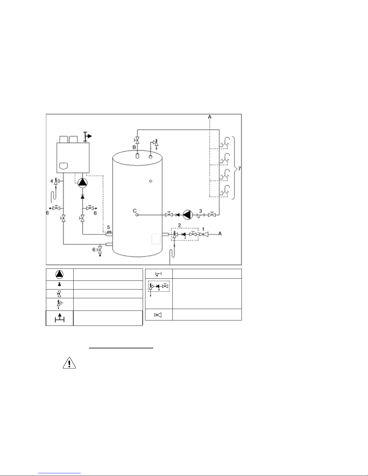
and regulations for tap water installations . Use the nex t scheme as guideli ne. When multiple water heaters and
tanks are applied, every combination should be equipped with its own safety valve.
A) Service pipe inlet
B) Hot water supply circulation
C) Circulation return
1) Pressure relief valve (m andatory in case ser vice water pressure is too high)
2) Inlet combination with valve
(mandatory)
3)
Apply filter if necessary
(recommended)
4)
A suitable safety valve
must be mounted near the
water heater (mandatory)
This safety valve may
never be isolated f rom the
w
ater heater by means of a
ball valve
5) Remote tank sensor (necessary) → mounting
hereof: see § 9.2.1 on page
35
6) Drain valve (recommended)
7) Hot and cold water mixers
SAFETY COMPONENTS
NB! The picture shows an example of a functional installation. The safety components as shown
in the picture are NOT necessarily conform all applicable standards and regulations.
ALWAYS have the system installed by a skilled installer. Safety must be added according to all
applicable standards and regulations.
PUMP
NON RETURN VALVE
VALVE
SAFETY VALVE
AUTOMATIC AIRVENT
FILTER
INLET COMBINATION
- Overflow
- Controllable return valve
- Valve
PRESSURE REGULATING
VALVE
MANUAL AIRVENT
Page 10

E93.0901EN.A Manual Consul+
10
TECHNICAL DATA CONSUL+ WATER HEATERS
2.1 Functional introduction
The CONSUL+ water heater is standard set for Natural gas G20
Gases used must meet the European standard EN 437.
Fuel used should hav e Sulphur rates accor ding t o the Europea n stan dard, a m axim um annual peak over a shor t
period of 150 mg/m
3
and an annual average of 30 mg/m3.
Water heater control includes the nex t programmable features:
Remote operation and heat demand indication from each water heater
Anti-Legionnaires’ disease f unction
0-10 VDC remote flow temperature (set point) control
NB! 0-10 VDC remote burner power input control is NOT possible for this type of direct fired water heaters.
0-10 VDC connection available
The water temperature c an be contr olled b y an extern al 0-10 V DC signa l. A signal of 1.48 Volt will switch o n the
water heater(s), less than 1.4 Volt will switch off the water heater(s).
Time program
Time programs with three programmable periods per day are available. These time programs are activated at the
control panel and off er great f lexibil it y in control ling th e water heater ’s day and night tem peratures as we ll as the
anti-Legionella settings.
Page 11
E93.0901EN.A Manual Consul+
11
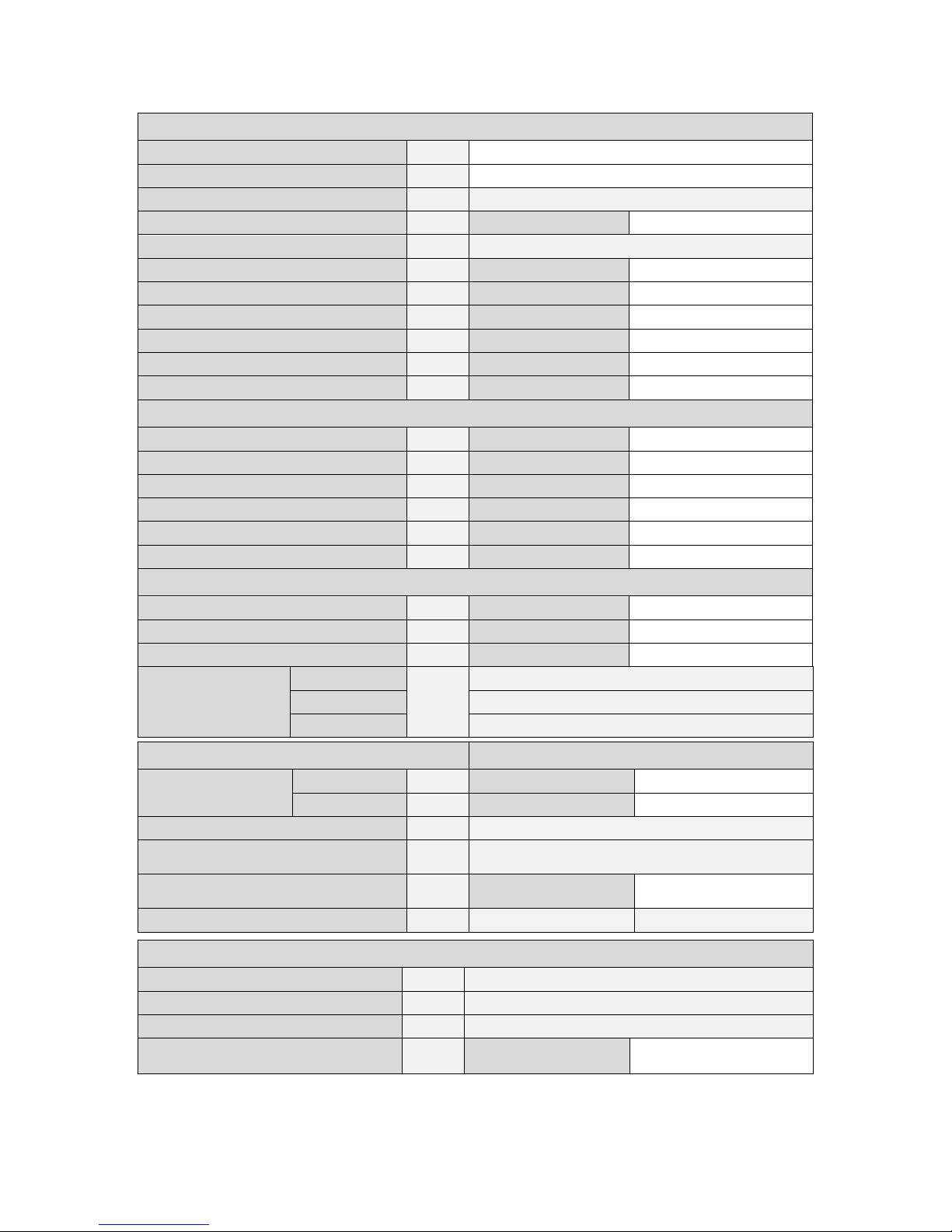
2.2 Table technical specifications
GENERAL
Product Identification number
CE 0063 BR3537
Classification Country depending II2EK3P
Gas Appliance Type B23; C13, C33, C43, C53, C63, C83
Type water heater
Consul+35 Consul+55
Dimensions (h x w x d) mm
516 x 405 x 310
Water content est. Littre’s 2,3 3,4
Weight dry kg 22 26
In- and outlet water connection inch R 1½ʺ R 1½ʺ
Gas connection inch R ¾ʺ R ¾ʺ
Flue/air concentric mm 80/125 80/125
Flue/air twin pipe mm 80/80 80/80
DOMESTIC HOT WATER Values min-max:
Nominal input (Net) kW 10,1 – 33,7 14,0 – 51,0
Nominal input (gross) (G20 G25.3)
kW
11,2 – 37,4 15,6 – 56,6
Nominal input (gross) (G31)
kW
11,0 – 36,6 15,2 – 55,4
Nom. output 80/60°C kW 9,6 - 32,1 13,4 - 50,5
Nom. output 50/30°C kW 10,4 – 34,7 14,2 – 53,7
Nom. output 37/30°C kW 10,8 – 36,3 15,1 – 57,1
GAS CONSUMPTION gases acc. to EN437 Values min-max:
Natural gas G25.3 m³st/u 1,22 – 4,05 1,68 – 6,14
Natural gas G20 m³st/u 1,07 – 3,57 1,48 – 5,40
Propane gas G31 1 m³st/u 0,41 – 1,38 0,57 – 2,09
Gas supply pressure
nom.
2
G25.3
mbar
25
G20 20
G31 30/37
EMISSION Nominal values at min-max load
CO2 flue gas
min-max 3
G25.3/G20 % 8,7 - 9,0
8,7 - 9,0
G31 % 9,5 - 10,5 9,5 - 10,5
NOx class [ EN15502-1] -
6
Temperature flue gas at
combustion air temp = 20°C
°C ~ 85-95
Mass flow flue gas [min-max]
Q
fluegas
condensing
g/s 3,86 - 17,48 5,78 - 27,44
Available pressure for the flue system 4 Pa 100 120
INSTALLATION
Max. water temperature °C 75
Pressure WW-system min-max bar 1,0 – 8,0
Relief valve pressure max bar 10
Max. available pump pressure for the
installation at ∆T = 17 K
mWK 2.8 2.7
Page 12
E93.0901EN.A Manual Consul+
12
Gas type G25.3 Only applicable to the Dutch manual
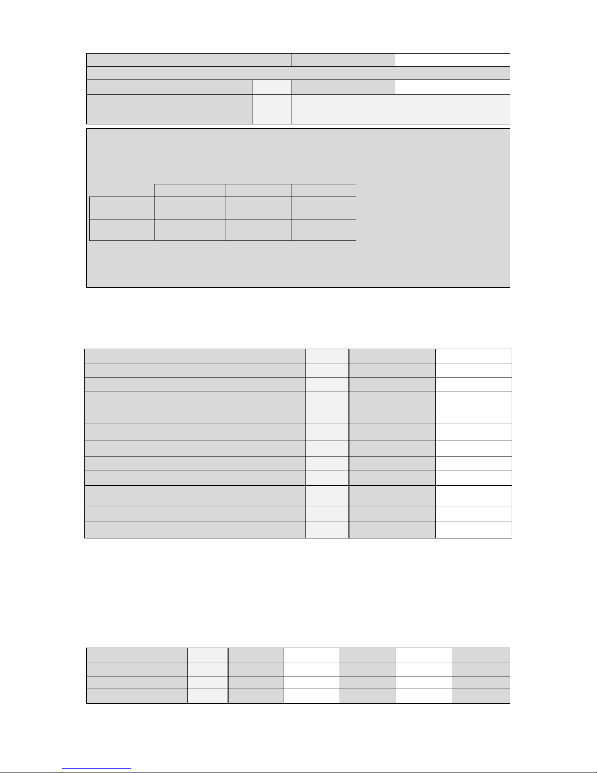
2.3 Table technical specifications ERP
Type water heater:
Consul+35
Consul+55
Load profile XL
XXL
Water heating energy efficiency class
A
A
Unit:
Water heating energy efficiency (η
wh)
%
85,5 86,9
Daily fuel consumption (Q
fuel)
GJ
0,079 0,100
Daily electricity consumption (Q
elec)
kWh
0,169 0,194
Annual fuel consumption (AFC)
GJ
17
22
Annual electricity consumption (AEC)
kWh
37
43
Emissions (Nox) of nitrogen oxides
(EN15502-1:2012+A1:2015)
mg/kWh
36 33
Thermostat temperature setting
ºC
55 - 70
55 - 70
Sound power level, indoors(Lwa)(EN 15036-1:2006)
dB(A)
61 61
A Consul+ water heater appliance should b e instal le d with a wat er tank.
The efficiency of the complete installation depends on:
· type of water tank. · volume of the water tank.
· type of circulation pump. · length of the connecting pipes.
· insulation of the connecting pipes.
Depending on the applied tank volume, the load profile might be higher.
2.4 ERP specifications Ecohs water tanks.
Type water heater
Consul+35
Consul+55
ELECTRIC
Power consumption (without pump). W 55 90
Power suppl y V / Hz 230 / 50
Protection class IPX4D
NOTES
1
Using propane G31, maximum fan speed needs to be reduced (parameter P4BD)
2
Below, a table is given in which the min. and max. gas supply pressures are mentioned acc.
to EN437
p nom.[mbar]
p min [mbar]
p max [mbar]
G25.3
25
20
30
G20
20
17
25
G31
30
25
35 37
25
45
3
CO2 of the unit measured/set without the water heater front door in place
4
Maximum allowed combined resistance of flue gas and air supply piping at high fire
Water Tank Type:
EWD150
EWD230
EWD300
EWD450
EWD750
Energy label
C C C D n.a.
Standing loss (S)
Watt
61,3
78,8
96,3
114,2
142,08
Storage volume (V)
liter
153
240
305
438
750
Page 13
E93.0901EN.A Manual Consul+
13
DIMENSIONS
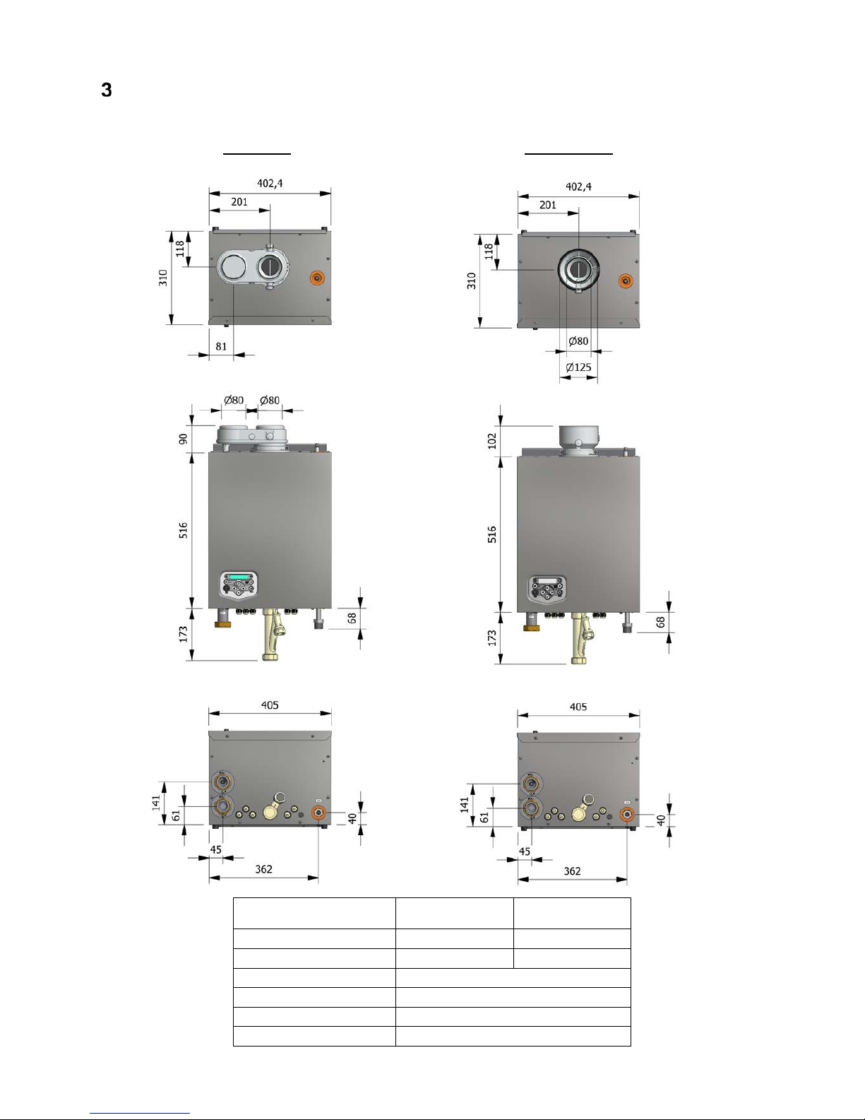
3.1 Water heaters CONSUL+ 35
TWIN PIPE CONCENTRIC
Connections
Consul+35
twin pipe concentric
flue gas
Ø80
Ø 80
air inlet
Ø80
Ø125
cold water inlet
R 1½” (swivel)
hot water outlet
R 1½” (swivel)
gas R ¾” (male)
condensate
flexible hose Ø25/21 x 750 mm.
Page 14
E93.0901EN.A Manual Consul+
14
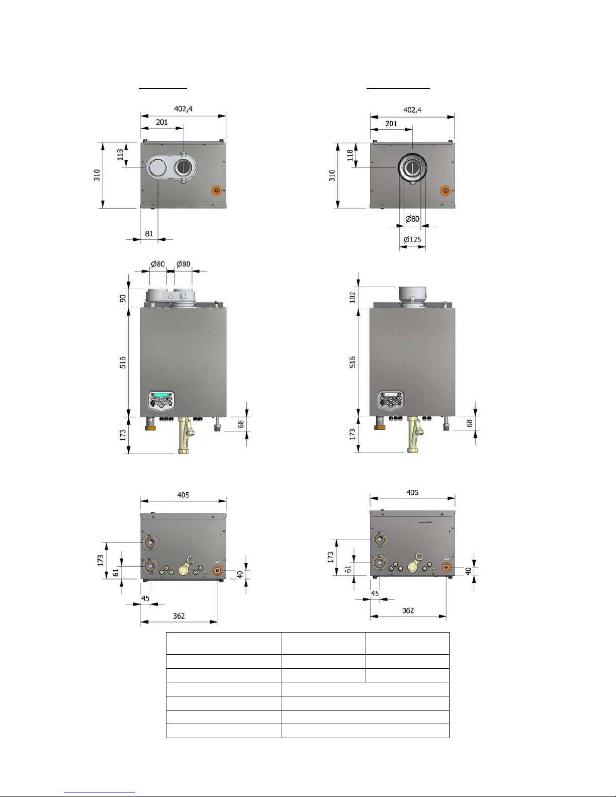
3.2 Water heaters CONSUL+ 55
TWIN PIPE CONCENTRIC
Connections
Consul+35
twin pipe concentric
flue gas
Ø80
Ø 80
air inlet Ø80 Ø125
cold water inlet
R 1½” (swivel)
hot water outlet
R 1½” (swivel)
gas R ¾” (male)
condensate
flexible hose Ø25/21 x 750 mm.
Page 15
E93.0901EN.A Manual Consul+
15
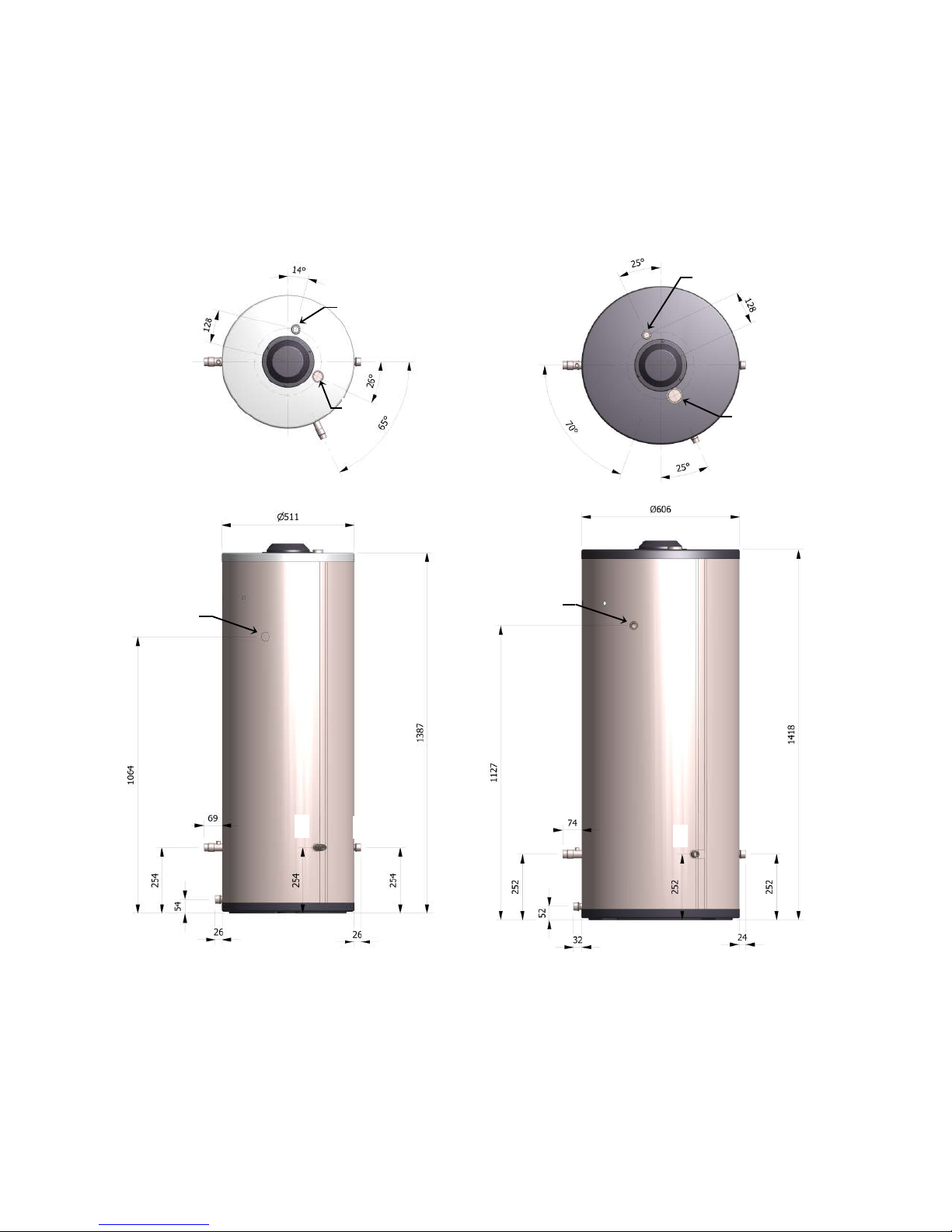
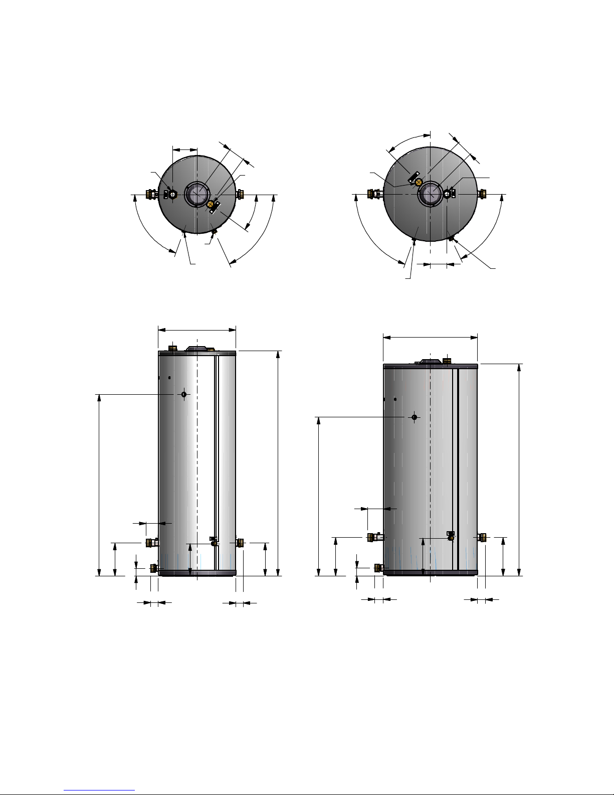
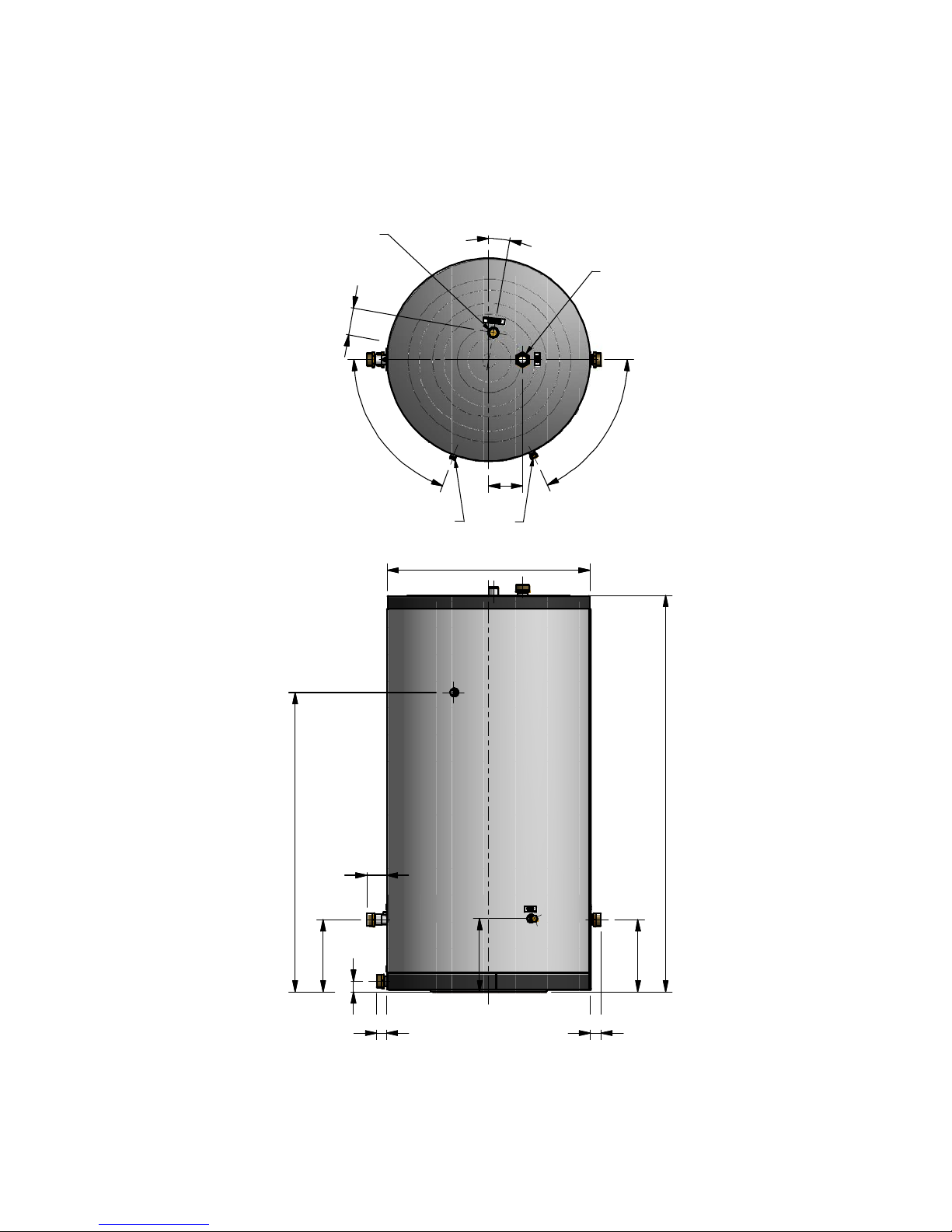
3.3 Tank EWD150 – EWD230 - EWD300 - EWD450 - EWD750
For the connections, marked A-H see § 9.3.2 on page 45-46
EWD150 EWD230
A B C
D
E F H
A
B
C
D
E
H
F
Page 16
E93.0901EN.A Manual Consul+
16
EWD300 EWD450
1
7
5
0
6
04
6
0
2
5
7
2
5
7
5
6
92
56
3
6
°
7
0
°
6
5
°
73
4
C
A
B
D
F
H
E
1
90
128
7
0
°
6
5
°
4
5
°
1
2
8
1
2
8
C
A
B
63
63
121
6
0
2
9
7
2
9
7
1
6
4
6
D
E
F
H
2
9
2
2
4
4
1
4
1
2
1
2
3
2
Page 17
E93.0901EN.A Manual Consul+
17
EWD750
9
50
7
0
°
6
5
°
15
8
1
0
°
1
2
8
47
92
47
3
3
8
1
8
5
9
5
0
3
3
8
C
A
B
F
H
D
E
3
4
3
1
4
0
3
Page 18

E93.0901EN.A Manual Consul+
18
ACCESSORIES AND UNPACKING
4.1 Unpacking
The CONSUL+ water heater will be supplied with the following documents and accessories:
• One “Installation User and Mounting” manual
• One suspension bracket with locking plate and bolts.
• Attached to the front of the gas valve:
- Two spare fuses
- Three spare nuts for mounting the burner plate.
- A gas conversion sticker
• Temperature sensor with connector, Siphon drain hose and a dirt catcher siphon
• Double Nipple (2 pieces) with gaskets and support nipples to be used for the flow and return pipe.
• Pump Grundfos UPXML GEO 25-125-N-180
After delivery, immediately check the water heater package to see if it is complete and without any defects.
Report any imperfections immediately to your supplier.
4.2 Accessories
Depending on the selected way of controlling the system, the following items can be supplied with the water heater.
Ask your supplier for the specifications.
Item
Part Nº.
External DHW-Tank threaded temperature sensor 10kOhm@25°C ( supp lie d with the
water heater), to be mounted in the screw hole on the tank outlet to the water heater
E04.016.677
External DHW-Tank pipe temperature sensor 10kOhm@25°C for tank types without
screw hole in the outlet to the water heater
E04.016.304
Warm water thermostat RCH S04.016.658
Hot water tank, stainless steel, EWD150 E66.000.010
Hot water tank, stainless steel, EWD230 E66.000.011
Hot water tank, stainless steel, EWD300 E66.000.203
Hot water tank, stainless steel, EWD450 E66.000.204
Hot water tank, stainless steel, EWD750 E66.000.205
Baseplate EWD150 - EWD450 tanks E01.000.412
Baseplate EWD750 tank E01.000.411
Pump Grundfos UPXML GEO 25-125-N-180 E04.016.705
Software and interface cable to program the water heater with a computer/laptop S04.016.586
Page 19

E93.0901EN.A Manual Consul+
19
4.3 Flue gas and air supply parts
Twin pipe Concentric pipe
Twin pipe air and flue diameters:
Ø80
Conversion kit conc. to twin pipe
E61.001.188
Flue gas pipe SS L=1000mm
E04.018.055
Flue gas pipe SS L=500mm
E04.018.054
Flue gas pipe SS L=250mm
E04.018.053
Flue gas pipe PP L=1000mm
410085502
Flue gas pipe PP L=500mm 410085501
Flue gas pipe PP L=250mm
410085500
Adjustable pipe PP
410085027
All-purpose lead tile roof terminal
E04.018.031
Concentric roof terminal SS.
E04.018.015
Tile roof terminal
E04.018.032
Single pipe roof terminal PP
410086883
Condensate drain stainless steel
E04.018.058
Condensate drain PP
410085048
Wall pipe clamps
E04.018.083
Roof deck pipe clamps
(included in roof
term.)
Seal ring rubber
S07.004.023
Bend stainless steel 43-45°
E04.018.057
Bend stainless steel 87-90°
E04.018.056
Bend PP 43-45°
410085042
Bend PP 87-90°
410085041
Concentric wall terminal
E04.018.019
Air supply wall terminal 410082856
Manifold Air-Flue gas
(Twin-Conc)
E04.010.161
Concentric pipe diameters air and flue:
Ø80/125
Conversion kit twin pipe to concentric
E61.001.189
Flue gas pipe SS L=1000mm
E04.018.016
Flue gas pipe SS L=500mm
E04.018.067
Flue gas pipe SS L=250mm
E04.018.066
Flue gas pipe PP L=1000mm
E04.018.020
Flue gas pipe PP L=500mm
E04.018.025
Flue gas pipe PP L=250mm
E04.018.024
Adjustable pipe PP
410084457
All-purpose lead tile roof terminal
E04.018.031
Concentric roof terminal SS
E04.018.015
Roof pipe flashing
E04.018.032
Concentric roof terminal PP
E04.018.018
Air seal ring concentric roof terminal
08 1078 00
Concentric condensate drain SS
E04.018.069
Concentric condensate drain PP
E04.018.028
Wall pipe clamps
E04.018.085
Roof deck pipe clamps
E04.018.030
Seal ring gummi – Flue gas pipe
S07.004.023
Seal ring gummi – Air pipe
E07.004.024
Conc. bend SS 43-45°
E07.004.027
Conc. bend SS 87-90°
E04.018.017
Conc. bend PP 43-45°
E04.018.027
Conc. bend PP 87-90°
E04.018.021
Concentric wall terminal stainless steel
E04.018.019
Page 20
E93.0901EN.A Manual Consul+
20
INSTALLATION OF THE CONSUL+
5.1 General notes
At every side of the water heat er at least 50 mm of clearance s hould be applied to walls or wall units, 350 mm
above the top side of the water heater and 250 mm from the bottom of the water heater.
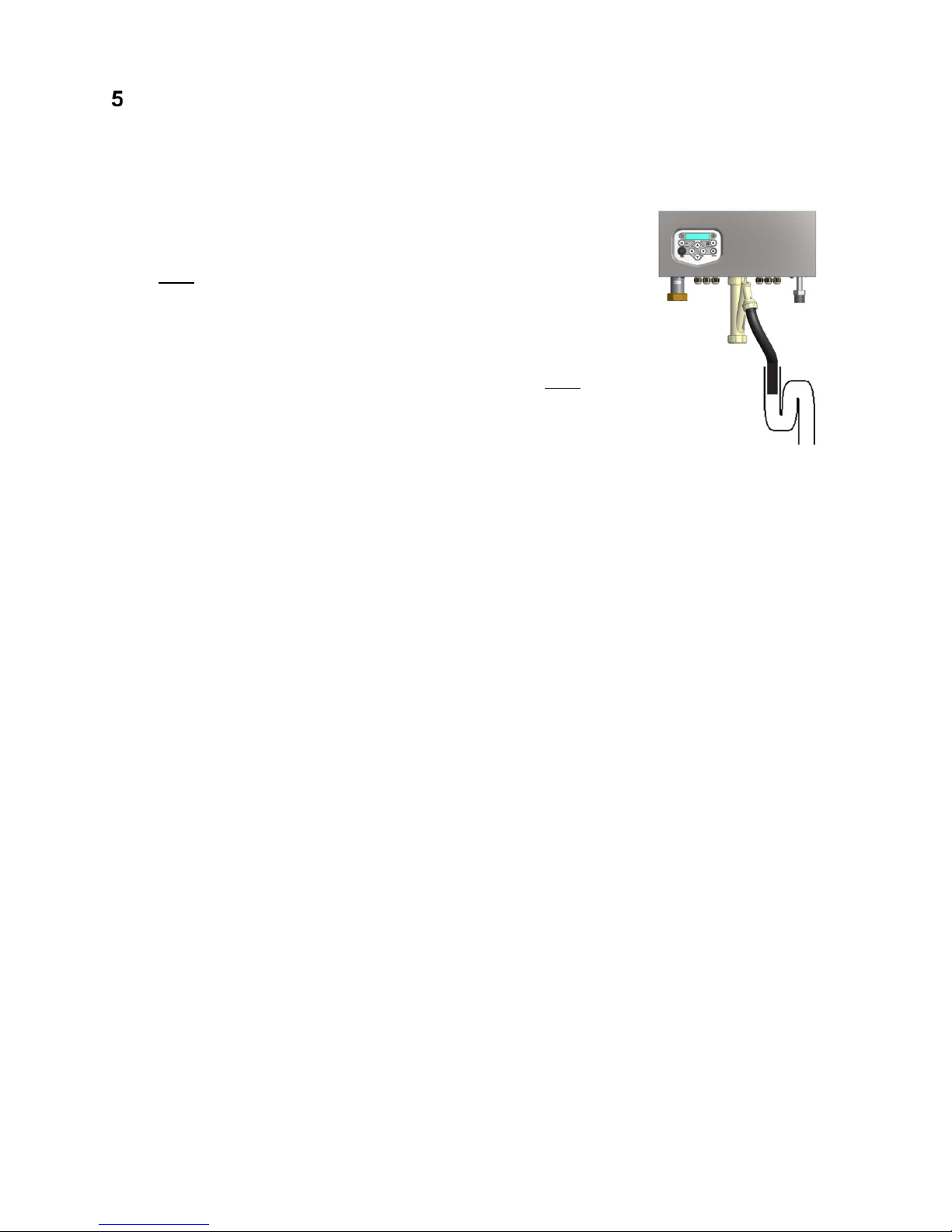
The installation area/room must have the following provisions:
• 230 V - 50 Hz power source socket with earth connection.
• Open connection to the sewer system for draining condensing water
• Gas connection.
Note:
The wall used f or mounting the water h eat er must be able to ho ld th e w eig ht of th e water heater. If th is is no t the
case it is recommended to mount the water heater on a (cascade) frame.
Other considerations related to the water heater location:
• The ventilation of the plant room m ust meet all applicable standards and regulat ions, regardless of the
selected supply of fresh air to the water heater location.
• Both the air supply and the flue gas tubes must be connected to the outside wall and/or the outside roof.
• The installation area must be dry and frost-free.
• The water heater has a built-in fan that will generate noise, depending on the total heat demand. The water
heater location shou ld minimize a ny disturbanc e this m ight cause. Pref erabl y it is suggested to m ount the
water heater on a brick wall.
• There must be sufficient lighting available in the plant room to work safely on the water heater.
• Remind the positioning of electrical components in relation to the temperature sensitivity.
• Make sure there is an open connection with the sewer to drain the condensate. This connection should be
lower than the condensate drain level of the water heater.
The water heater must be positioned and instal led by a certified inst aller in accordanc e with all applicable st andards and regulations . Com m issionin g of the water he ater must be done by a skilled serv ice/comm iss ioning engineer, trained for this type of water heater.
Open connection to the sewer.
Page 21
E93.0901EN.A Manual Consul+
21
5.2 Mounting the water heater and tank
5.2.1 WATER HEATER MOUNTING
Before mounting and installing the water hea ter the following connections should be considered:
• Flue gas system and the flue gas pipe connections
• Air supply system and connections
• ‘Cold in’ and ‘hot out’ pipe connection
• Condensate and pressure relief valve drainage
• Power supply (preferably the power connection is positioned above the water heater)
• Gas connection.
All lines/piping m ust be mounted free of te ns io n. T he weight of all the inst a llati on c omponents should be
supported separately from the water heater so there will be no standing force on the connections.
This might influence the mounting position of the water heater.
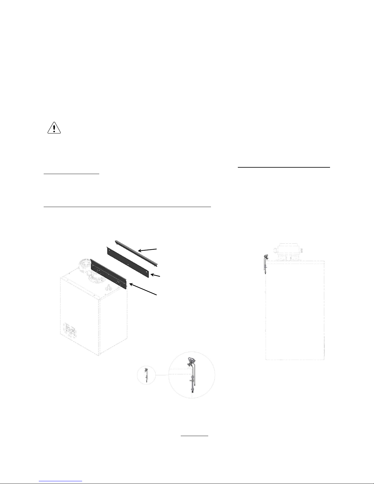
Determine the position of the flow and return pipes by using the included sus pension bracket or a suspe nsion
frame (when supplied).
While marking the holes, ensure that the sus pension brack et or frame is perpendicular and the water heater
does not lean for ward. If necessary, adjust the pos iti on with the adjus ting bolts at t he lower rear s ide of the back
panel (see drawing). When the adjusting bolts aren’t sufficient, fill the gap behind the bolts to get the water heater
in position. The exact water heater position lies between the water heater hanging level and hanging slightly backwards.
The water heater should not lean forward in the mounted position.
Lock the suspension bracket with the security cover before making any other connections to the water heater. This
security cover will prevent the water heater from falling off the bracket. Don't use excessive force during the mounting of the water heater connections.
Suspension detail
5.2.2
TANK POSITIONING
The tank must be placed* on a stable floor, but not too far from the water heater(s).
* NB! This floor must be able to hold the weight of the water filled tank(s).
3. Lock water heater with locking
plate and two bolts
1. Attach mounting bracket to wall
with inclined side facing upwards
2. Suspend water heater with suspension bracket on mounting
bracket
Page 22

E93.0901EN.A Manual Consul+
22
FLUE GAS AND AIR SUPPLY SYSTEM
6.1 General
The water heater has a pos itive pr ess ur e f lue system. The available c ombined pressure dro p for the air inlet and
flue gas outlet s ystem, for a single water heater type Consul+3 5, is 100 Pa and for a Consul+55 its 120 Pa
maximum.
It’s not allow ed to use an overpressure s ystem f or a mult iple water heater installation, alwa ys contact the m anufacturer for advice.
Notice:
• Install the horizonta l flue components with an angle of 3° downwards in the direction of the water heater
(roughly equal to five centimeters for every linear m eter). When not installed according ly, it may result i n
condensate building-up in the flue gas tube, eventually causing component failure.
• When using a wall terminal , there is th e possibl e risk of ice b uildin g-up on s urroundi ng parts/s tructures , be-
cause the condensate will freeze. This risk should be considered during the design phase of the DHW installation.
Note:
Because the flue gases can have a relatively low temper ature, the water heater needs to hav e a high eff iciency
approved stainless steel or plastic f lue system. These m aterials should be us able f or the applied pressure in the
flue gas system, be condensate proof and have a temperature class of T120.
Before installing, read the installation manual(s) of the supplier of the flue gas and air supply parts
included with the parts. Manuals for parts supplied by ECO can be found at:
http://burgerhout.nl/documenten/handleidingen/
(Only Dutch language available).
Undermentioned manuals for parts supplied by ECO HS are applicable:
- Regulations regarding flue gas systems PP(s)
- Installation instructions clamps: Checklist
- Installation Instructions Skyline 3000
Page 23
E93.0901EN.A Manual Consul+
23
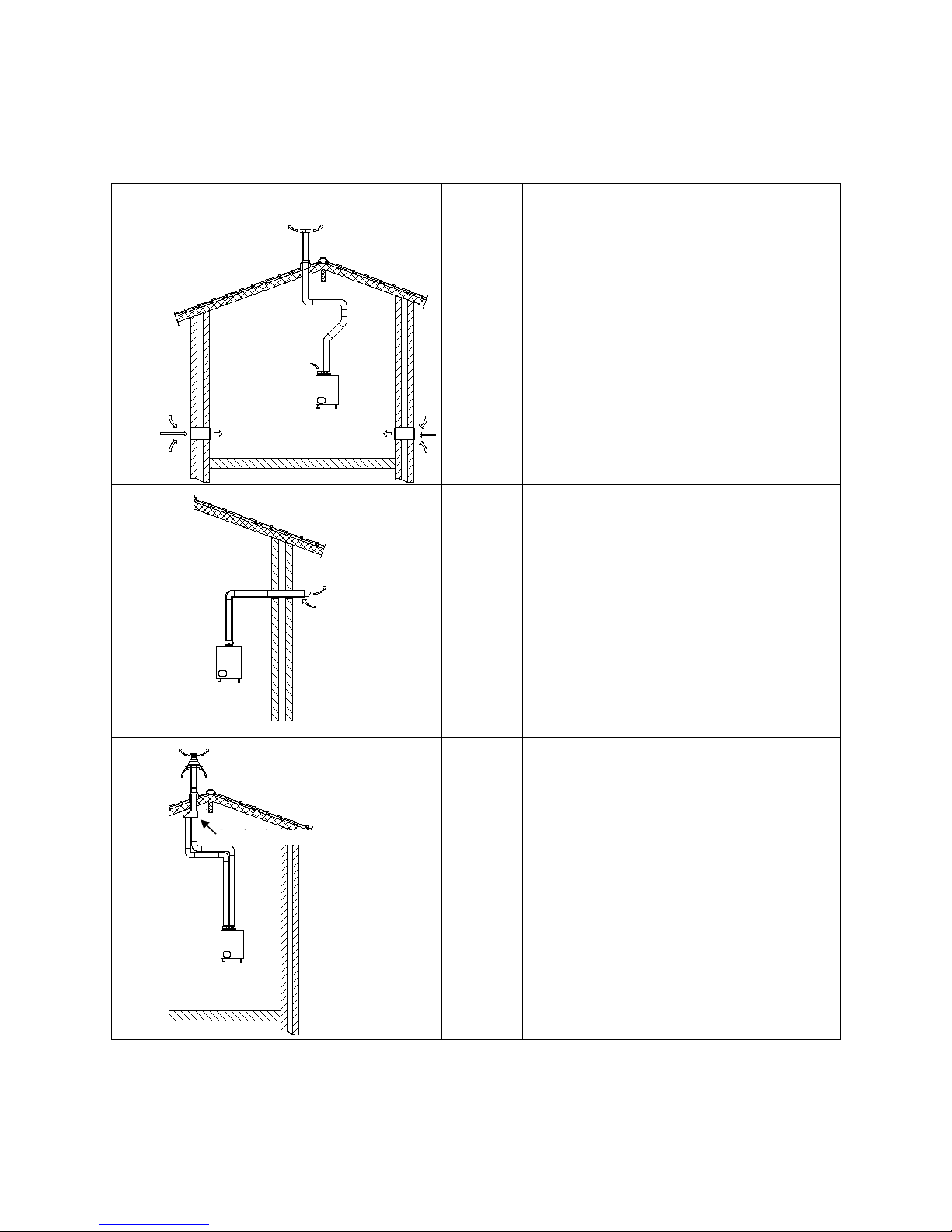
6.2 Type of flue gas systems.
Please contact your supplier in case of C43 and C83 applications.
Type according EN 15502-2-1: 2012
Performance
Description
B23(P)
Open
Air supply
from r oom
* Roof terminal
* Without draught diverter
* Water heater room air supply.
* P = overpressure systems
See c
hapter: Accessories –
Flue gas and air supply parts - TWIN PIPE
See:
Six typical examples - example C
Be
aware: T he installation room must have
sufficient air suppl y vents. These
vents must be open an d may not
be closed or blocked.
Requirements at NEN 3028 paragraph 6.5
C13
Closed
Air supply
from outside
*Wall outlet.
*Air supply inlet and flue gas outlet at the
same air pressure zone.
(a combined wall outlet e.g.).
Wh
en used with separated air supply inlet and
flue gas outlet the outlets must be within a
square of 50 cm
See c
hapter: Accessories –
Flue gas and air supply parts - CONCENTRIC
See: Six typical examples - example E
C33
Closed
Air supply
from outside
* Flue terminal at the roof.
* Air supply inlet and flue gas outlet located at
the same air pressure zone
(a combined roof terminal e.g.).
Wh
en used with separated air supply and flue
gas outlet the outlets must be within a square
of 100 cm
And the distance between the planes of the
two transits must be smaller as 50 cm
See c
hapter: Accessories –
Flue gas and air supply parts - TWIN PIPE
See:
Six typical examples - example B
Dakdoorvoer
Broekstuk
Flue outlet
Air inlet
Air inlet
Vented
area
Concentric wall outlet
Concentric /parallel adaptor
Concentric roof terminal
Page 24
E93.0901EN.A Manual Consul+
24
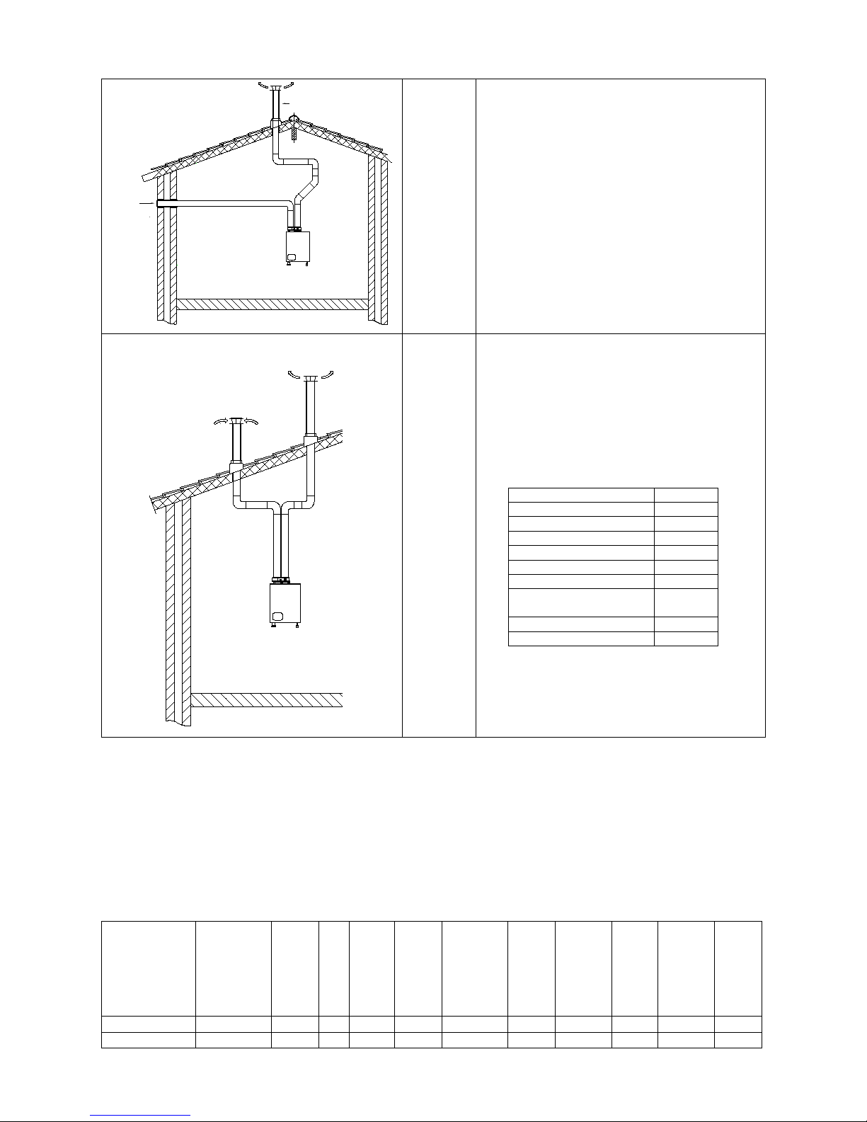
C53 Closed
Air supply
from outside
*Separate air supply duct
*Separate flue gas discharge duct.
* Air supply inlet and flue gas outlet at differ-
ent air pressure zones. But not at opposite
walls.
See chapter: Accessories –
Flue gas and air supply parts - TWIN PIPE
See: Six typical examples - example F
C63 Closed
Air supply
from outside
* Appliance sold without flue/air-inlet ducts
* The flue gas parts are not part of the water
heater. The water heater is intended to be
connected to a separately approved and marketed system for the supply of combustion air
and discharge of combustion products.
Condensate can go to the water heater.
* Air supply inlet and flue gas outlet not at op-
posite walls
* Technical data:
nominal T
flue gas
85°C
nominal Q
fluegas
See 2.2
1)
maximum T
fluegas
95°C
min. load T
fluegas
35°C
min. load Q
fluegas
See 2.21)
nominal % CO2
See 2.21)
max. allowed draft
70Pa
max. pressure drop in-
let-outlet
See 2.2
max T
air supply
40°C
max recirculation
10%
1) table technical specifications
See chapter: Accessories
- Flue gas and air supply parts
- TWIN PIPE
See: Six typical examples - example A
6.3 C63 certified
In general, water heater s are certified with their own flue gas material. For t ype B23, C13, C33, C43, C53, C83
systems, only use flue gas and air supply parts approved according §4.2 and §4.3.
If a water heater is C63 certified, no specific type flue gas material has been certified in combination with the water
heater. In this case the flue gas and air suppl y parts should com ply with the appl icable European standards
(EN14989).
So, for type C63 systems flue gas and air supply parts from other suppliers can be used. It must be able to handle
the condensate form ing (W) and transport, o verpressure (P1) and m ust have a minimum temperature class of
T120. Also, it must meet the requirements in the following chapters "air supply" and "flue terminal".
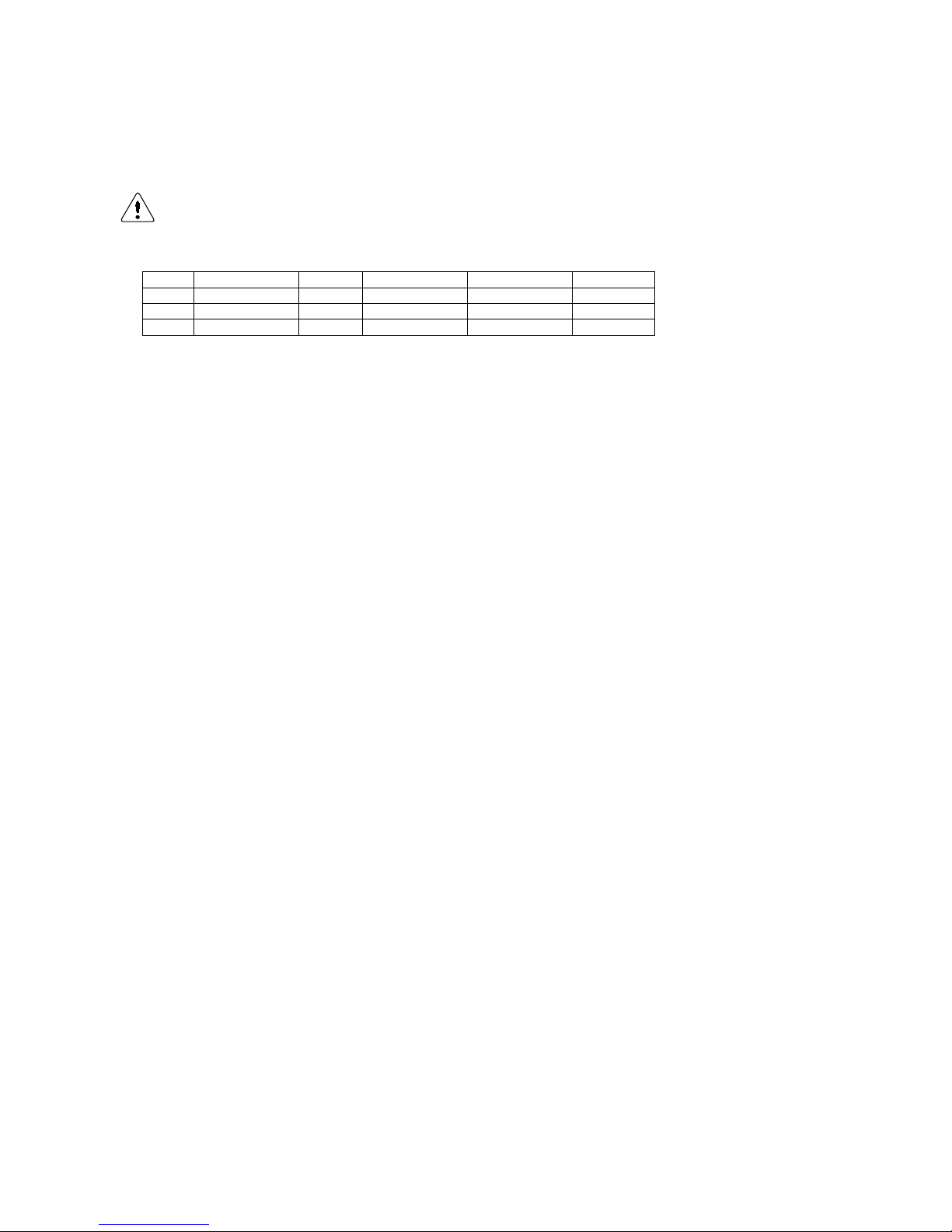
CE string
flue gas
material
European
standard
Temperature
class
Pressure class
Resistance to
condensate
Corrosion re-
sistance cla ss
Metal: liner
specifications
Soot fire re-
sistance cla ss
Distance to
combustible ma-
terial
Plastics:
location
Plastics: fire be-
haviour
Plastics:
enclosure
min. req. PP
EN 14471
T120
P1 W 1 O
30
I of E
C/E
L
min. req. SS
EN 1856-1
T120
P1 W 1
L20040
O
40
Flue outlet
Air
inlet
Flue outlet
Air inlet
Page 25
E93.0901EN.A Manual Consul+
25
A few examples of flue gas material suitable fo r ECO water heaters:
CE String for Plastic PPs: EN14471 T120 P1 W 2 O(30) I C/E L
CE String for Stainless Steel: EN1856-1 T250 P1 W V2-L50040 O (50)
When selecting flue gas systems, be aware that the minimum requirements are met.
So only select flue gas materials having the same or better properties than this table.
Never use aluminum containing flue gas pipes in these water heaters.
Connecting diameters and tolerances:
mat
water heater
d
nom
D
outside
d
inside
L
insert
SS
C35 / C55
80
80 +0,3/ -0,7
81 +0,3/ -0,3
50 +2/ -2
PP
C35 / C55
80
80 +0,6/ -0,6
50 +20/ -2
Multiple water heaters can be connecte d to a common duct. T hese flue gas systems for multiple water heater
installations mus t al wa ys b e en gineer e d as zero or n e gati ve pres s ure systems; this to pre ven t th e risk of recirc ulation of the flue gases . Co nsult the f lue g as sup plier f or detai led information and engine ering. See also the c ascade manual for these multiple water heater installations.
More information about these common flue gas systems can be found at the cascade-installation manual. You can
find the cascade manual at the website: http://www.ecohs.nl/products/ambassador-/documentation/
6.4 Air supply
When an air suppl y duct is connect ed from the ou tside of the bui lding to the water heater, the water heater will
operate as a room-independent water heater (closed water heater). The air supply duct can be made of:
• PVC / PP
• Thin-walled aluminium
• Stainless steel
6.4.1 C
OMBUSTION AIR QUALITY
Combustion air must be f ree of contaminants. For ex ample: chlorine, amm onia and/or alkali a gents, dust, sand
and pollen. Notice that inst alling a water heater near a swimm ing pool, a washing m achine, laundr y or chem ical
plants does expose combustion air to these contaminants.
6.4.2 A
IR SUPPLY THROUGH HUMID AREAS
When the supply duct will be p laced in a water he ater room with moist air ( for exam ple: gree nhouses) , a doubl e
walled supply duct or an ins ulated duct mus t be used to prevent the pos sible condensat ion at the outside of the
duct. It is not possib le to insulate the internal air pipes of the water heater and therefore co ndensation at the
internal air canals must be prevented.
When roof mounted, the air supply duct needs to be protected against rain, so no water will be entering the water
heater.
No water is allowed to enter the water heater through the air inlet canal at any time.
Page 26
E93.0901EN.A Manual Consul+
26
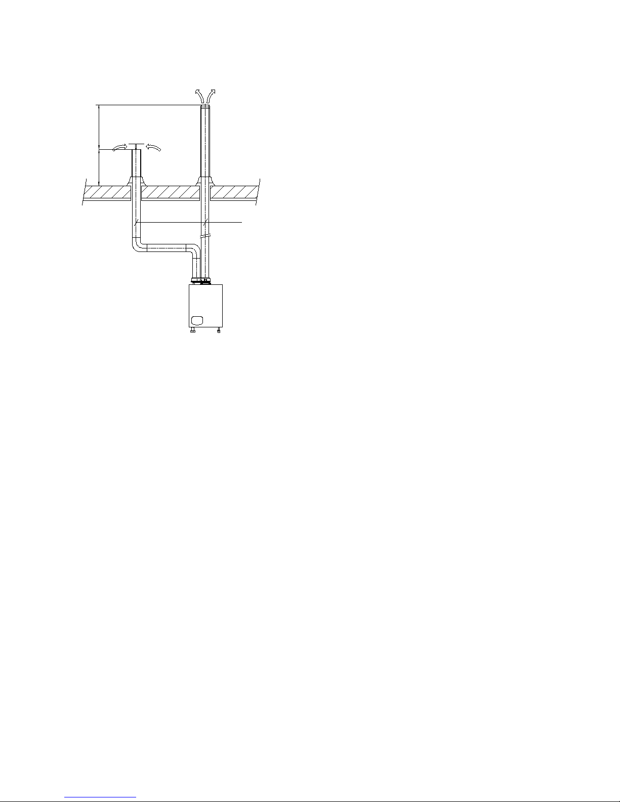
6.5 Heights abov e the roof.
Height A
This is the height of the air inlet. A rain hood should prevent
rainwater entering the air supply system.
When the inlet and outlet are mounted on a flat roof, the inlet
should be at least 60 cm above the roof surface and at least 30 cm
above the maximum snow level.
Example 1:
When the maximum s now level on the roof surfac e is 45 cm then
the air inlet shoul d be at 45+30=75 cm . 75 cm is more than the
minimum 60 so the height will be 75 cm.
Example 2:
When the maximum s now level on the roof surfac e is 15 cm then
the air inlet should be at 15+30=45 cm. 45 cm is less than the minimum 60 cm so the height will be 60 cm.
Height difference B
This is the height difference between the flue outlet and the
air inlet.
The flue gas outlet should be at l east 70 cm above the air inlet. It
is advised to be equipped with a conical outlet.
A single flue outlet should be situated at least 100 cm above
the roof surface.
Distance C
The horizontal distance between the flue gas pipe and air inlet
pipe at roof level.
This distance should be at least 70 cm.
A
B
C
Page 27
E93.0901EN.A Manual Consul+
27
6.6 Flue gas and air supply resistance table.
The load of the heater is affected by the resistance of the air supply and flue gas
system. This is caused by the controller of the heater regarding the gas-/ air link.
The maximum power d oes not drop m ore than 5% of the po wer mentioned at
the heaters data pl ate at a total (flue gas and air supply) res istance of 1 00 Pa
(Consul+35) and 170Pa (Consul+).
In the next sections, c alculation examples will be given to determine allowed
lengths of the flue gas and air supply pipes. First, the c omponent resistance
data are given in the next table:
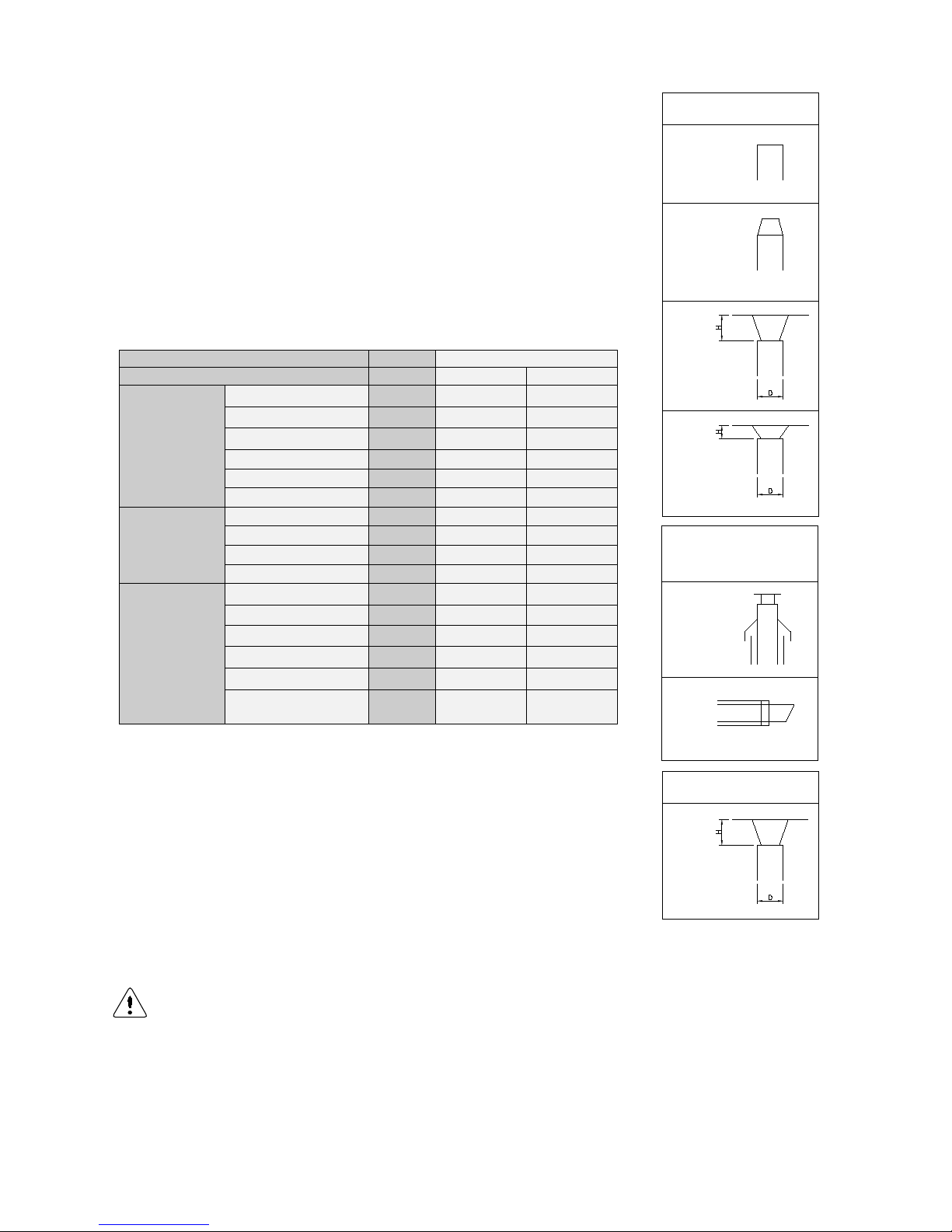
6.6.1
FLUE GAS AND AIR SUPPLY RESISTANCE TABLE
Ø [mm]
Resistance [Pa]
Item
Consul+35
Consul+55
Flue gas discharge
straight tube/m
80
4
5,3
45° bend
80
2
2.7
90° bend
80
4
5,3
outlet. zeta = 0.05
80
0,2
0,4
outlet. zeta = 1.0
80
3,5
9,2
outlet. zeta =1.5
80
5,3
12,6
Air supply
straight tube/m
80
3
4,1
45° bend
80
1,5
2,1
90° bend
80
3
4,1
inlet. zeta =1.0
80
4
10,2
Concentric
roof terminal
80/125
30
55
outside wall terminal
80/125
25
40
straight tube/m
80/125
7
10
90° bend
80/125
8
14
45° bend
80/125
5
9
Concentric /parallel
adaptor
80/125 7 10
NOTICE: This table can only be us e d f or a singl e f lue/ air system for one water he ater. D o NO T us e this ta ble
for common flue/air systems with cascaded water heaters
Also, using concentric pip es there is a second restr iction. The m aximum allowe d length stra ight con-
centric pipe to be used is 20 m. (flue gas pipe + air supply pipe).
AIR SUPPLY
H/D=1.0
zeta=1.0
CONCENTRIC FLUE
GAS OUTLET AND
AIR SUPPLY
ROOF
WALL
FLUE GAS DISCHARGE
zeta=0
open outlet
zeta=0.05
conical outlet
H/D=1.0
zeta=1.0
H/D=0.5
zeta=1.5
Page 28
E93.0901EN.A Manual Consul+
28
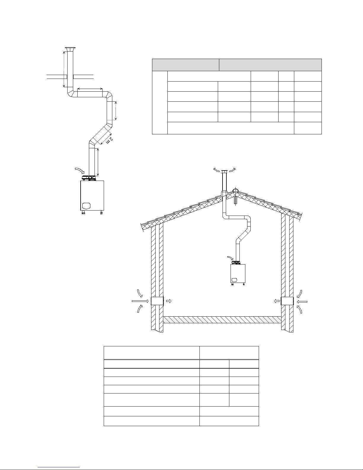
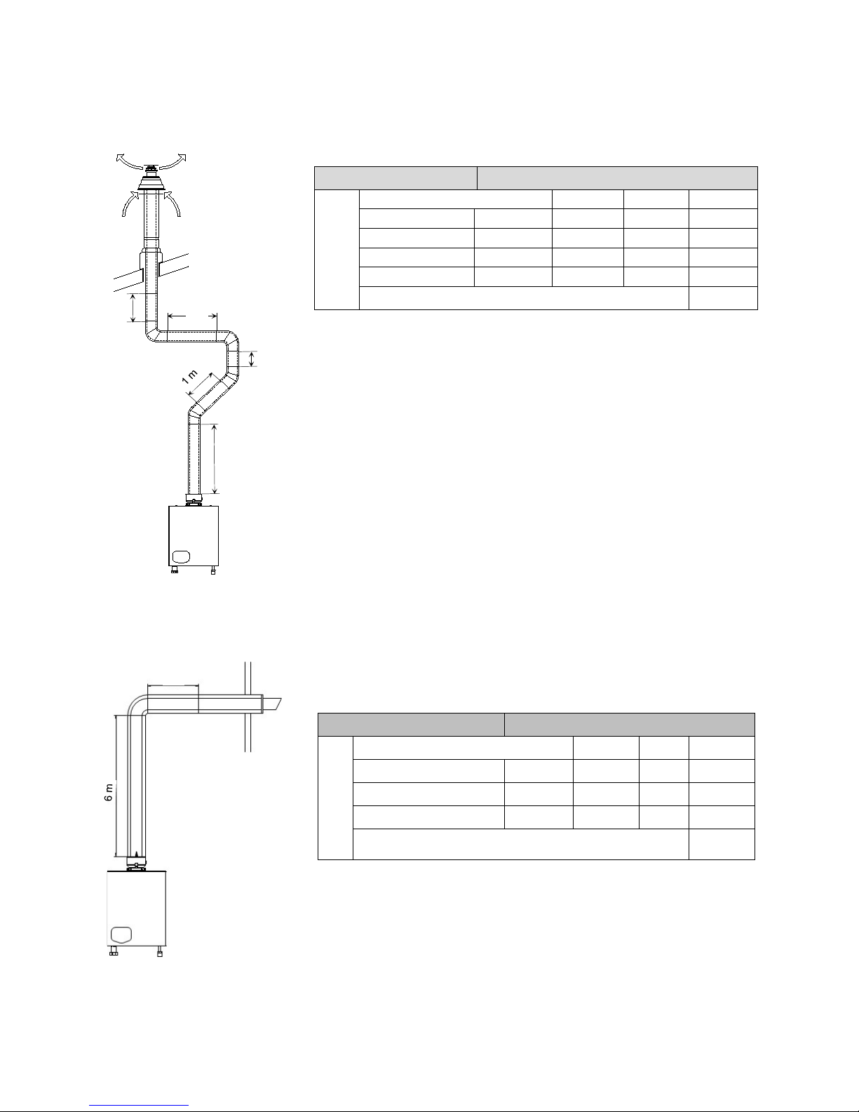
6.6.2 SIX TYPICAL EXAMPLES
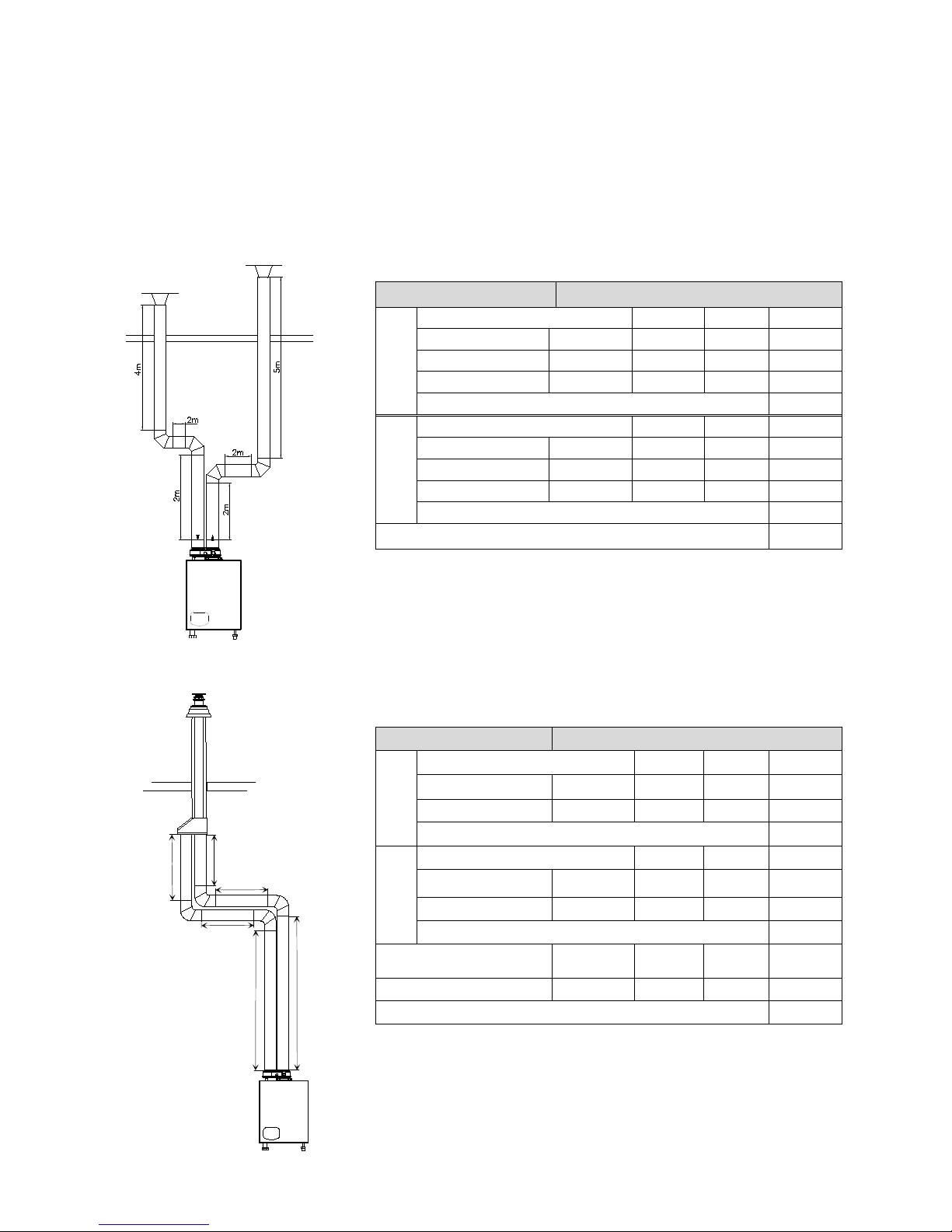
A: Twin pipe system with separate pipes for flue gas and air supply C63
B: Twin pipe system with separate pipes and concentric roof terminal C33
C: Single pipe for flue gas outlet only (air supply from water heater room)
B23
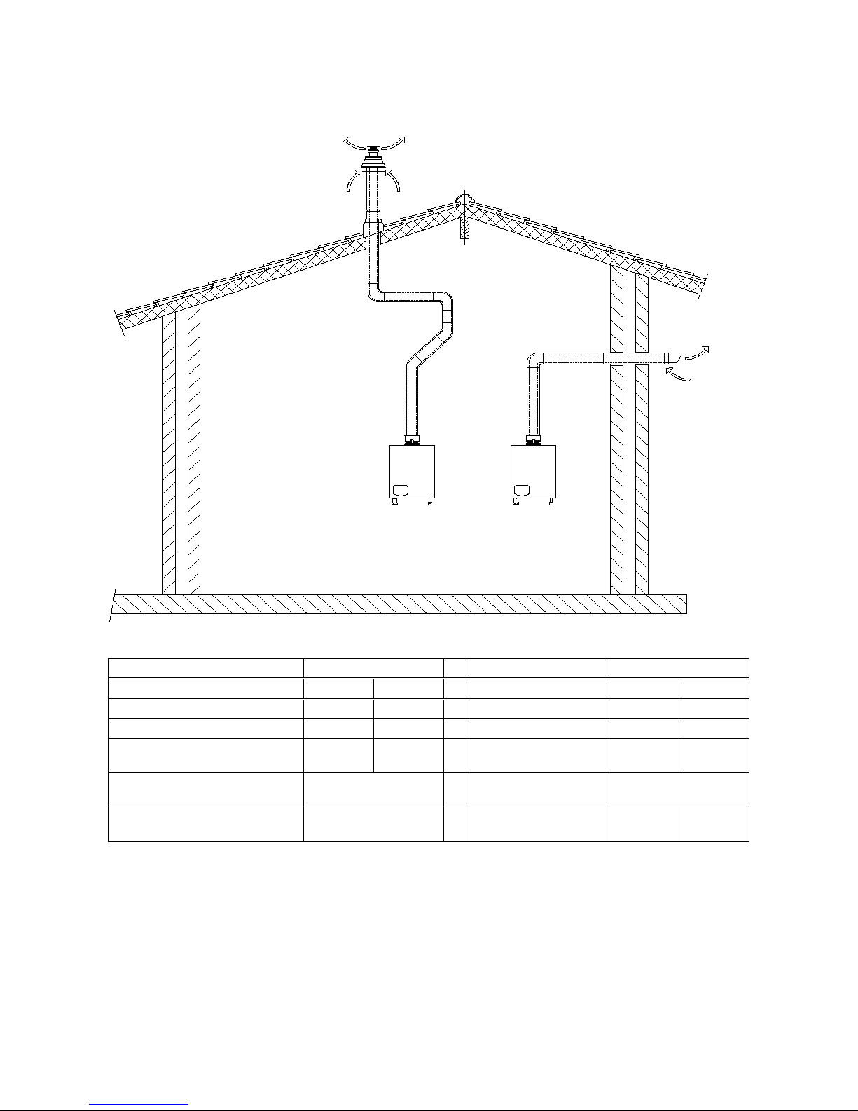
D: Concentric pipe for flue gas/air supply (roof-mounted) C33
E: Concentric pipe for flue gas/air supply (wall-mounted) C13
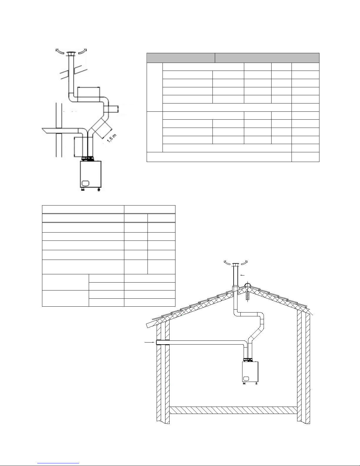
F: Separate air su pply duct & flue duct in different pressure zone C53
6.6.3
EXAMPLE A: TWIN PIPE SYSTEM (C63).
Calculation example with given lengths: checking resistance
The total resistance is less than 100 Pa. This flue gas / air supply system
is functional.
Be aware: Eco specific resistance values are used in this example. Flue
and air pipes of other supplier can have other values
Water heater type:
Consul+35
Flue gas
Diameter: 80 mm
Number
Pa
Pa total
Straight tube m¹ total 9 4 36,0
Bend
90° 2 4
8,0
Flue outlet
zeta = 1
1
3,5
3,5
Total resistance flue gas outlet:
47,5
Air supply
Diameter: 80 mm
Number
Pa
Pa total
Straight tube m¹
total 8 3
24,0
Bend
90° 2 3
6,0
Air inlet zeta = 1 1 4 4,0
Total resistance air supply:
34,0
Total resistance flue gas outlet and air supply: 81,5
6.6.4 EXAMPLE B: TWIN PIPE SYSTEM WITH SEPARATE PIPES AND CONCENTRIC ROOF TERMINAL (C33).
The total resistance exceeds 120 Pa. This flue gas / air supply system is
NOT functional.
Part number. roof terminal: E04.018.015 - Inox
Part number. adaptor conc/twin: E04.010.161 - Inox/PP
Water heater type: Consul+55
Flue gas
Diameter: 80 mm Number Pa Pa total
Straight tube m¹ total 6 5,3 31,8
Bend
90°
2
5,3
10,6
Total resistance flue gas outlet: 42,4
Air supply
Diameter: 80 mm Number Pa Pa total
Straight tube m¹ total 6 4,1 24,6
Bend
90°
2
4,1
8,2
Total resistance air supply: 32,8
Roof terminal
concentric
80/125
1 55
55,0
Adaptor par-conc 1 10
10
Total resistance flue gas outlet and air supply:
140,2
2 m
2 m
2 m
2 m
2 m
2 m
Page 29
E93.0901EN.A Manual Consul+
29
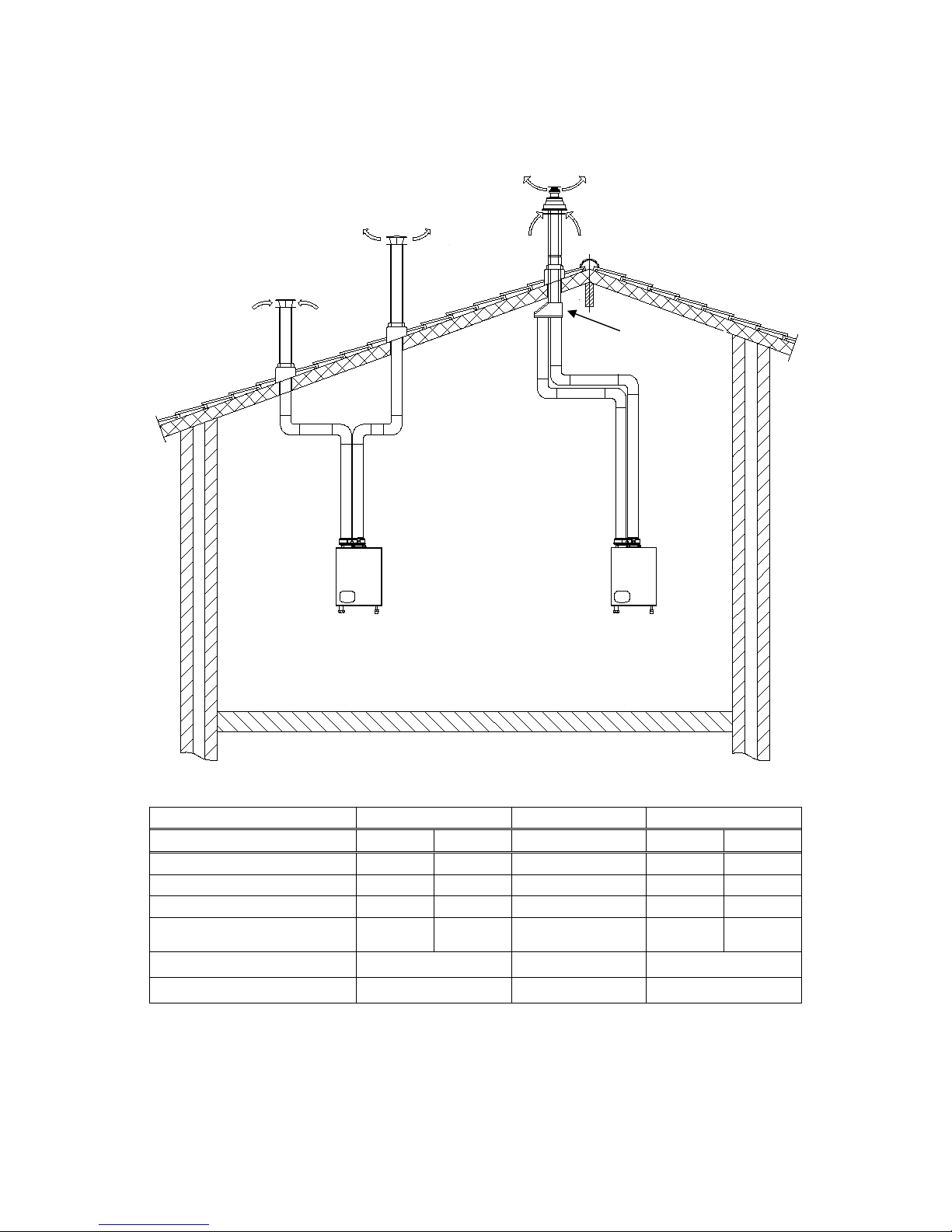
Example A (C63) and B (C33) maximum pipe lengths
Example A (C63)
Example B (C33)
Water heater type →
C+ 35
C+ 55
C+ 35
C+ 55
Diameter air inlet [mm]
80
80 80
80
Diameter flue outlet [mm]
80
80 80
80
Diameter roof terminal [mm]
80 80 80/125 80/125
Maximum pipe length [m]
(inlet + outlet together)
19 15 12 6
Part no. Twin roof terminal 410086883 conc. roof term.: E04.018.015
adaptor: E04.010.161
Example A
Example B
Concentric /parallel
adaptor
Concentric roof terminal
Flue gas outlet
Air inlet
Page 30
E93.0901EN.A Manual Consul+
30
6.6.5 EX. C: SINGLE PIPE FOR FLUE GAS AND AIR SUPPLY FROM WATER HEATER ROOM. (B23, B23P)
Calculation example with given lengths: checking resistance
The total resistance is less than 100 Pa. This flue gas / air supply system
is functional.
Water heater type: Consul+35
Flue gas
Diameter: 80 mm Number Pa Pa total
Straight tube m¹ total 13 4 52,0
Bend 90° 2 4 8,0
Bend 45° 2 2 4,0
Flue outlet H/D = 1,0 1 3,5 3,5
Total resistance flue gas outlet: 67,5
Maximum pipe lengths
Example C
(B23, B23P)
Water heater type →
C+ 35
C+ 55
Diameter air inlet [mm]
80
80
Diameter flue outlet [mm]
80
80
Diam. roof terminals [mm]
80
80
Maximum pipe length [m]
(inlet + outlet together)
21 17
Part no. concentric roof terminal SS. E04.018.015
Part no. adaptor conc/twin PP: 410086883
4 m
2 m
2 m
3 m
Flue gas outlet
Vented area
Example C
Air
inlet
Air
inlet
Page 31
E93.0901EN.A Manual Consul+
31
6.6.6 E
X. D: CONCENTRIC PIPE WITH ROOF OUTLET (C33).
The total resistance exceeds 120 Pa so this flue gas / air supply system is
NOT functional. Use larger pipe diameters or a shorter total pipe length.
Part number concentric roof outlet (SS): E04.018.015
Part number concentric roof outlet (PP): E04.018.018
6.6.7 EX. E: CONCENTRIC SYSTEM (WALL OUTLET C13).
Calculation example with given lengths: checking resistance
Water heater type: Consul 35 (C13)
Concentric
Diameter: 80/125 mm Number Pa Pa total
Straight tube m¹ total 9 7 63
Bend 90° 1 8 8
Conc. Wall outlet wall 1 25 25
Total resistance flue gas and air outlet:
(concentric)
96
The total resistance is less than 100 Pa. This flue gas / air supply system is
functional.
Part number concentric wall outlet (SS): E04.018.019
Water heater type: Consul+55
Flue gas and
air supply
Diameter: 80 mm
Number
Pa
Pa total
Straight tube m¹
total
6,5
10
65,0
Bend
90° 2 14
28,0
Bend 45° 2 9 18,0
Outlet/Inlet
80/125 1 55
55,0
Total resistance flue gas outlet and air supply 166,0
2 m
0,5 m
2 m
1 m
3 m
Page 32
E93.0901EN.A Manual Consul+
32
Example D and E maximum pipe lengths
Example D (C33)
Example E (C13)
Water heater type →
C+ 35
C+ 55
C+ 35
C+ 55
Diameter conc. pipe [mm]
80/125
80/125
80/125
80/125
Conc. Roof outlet [mm]
80/125
80/125
80/125
80/125
Maximum pipe length [m]
6 1 9 6
Part number conc.
Roof outlet (SS)
E04.018.015
Part number conc.
Wall outlet (SS)
E04.018.019
Part number conc.
Roof outlet (PP)
E04.018.018
Example E
Example D
Concentric
roof outlet
Concentric
wall outlet
Page 33
E93.0901EN.A Manual Consul+
33
6.6.8 AIR SUPPLY AND FLUE GAS OUTLET AT DIFFERENT PRESSURE ZONES (C53)
Calculation example with given lengths: checking resistance
T
he total resistance is less than 120 Pa. This flue gas / air supply system is functional.
Part number wall air supply: 41.008.28.56
Part number flue gas outlet: 41.008.68.83
Water heater type: Consul+ 55
Flue gas
Diameter: 80 mm
Number
Pa
Pa total
Straight tube m¹
totaal
6
5,3
31,8
Bend 45° 2 2,7 5,4
Bend
90°
2
5,3
10,6
Flue gas outlet
zeta = 1
1
9,2
9,2
Total resistanceflue gas outlet:
57,0
Air
Diameter: 80 mm
Number
Pa
Pa total
Straight tube m¹
totaal
2
4,1
8,2
Bend
90°
1
4,1
4,1
Air inlet H/D = 1,0 1 10,2 10,2
Total Resistance Air supply:
22,5
Total Resistance Air supply en Flue gas outlet: 79,5
Example F
Water heater type →
C+ 35 C+ 55
Diameter wall outlet [mm] 80 80
Diameter air inlet [mm] 80 80
Diameter flue gas outlet [mm] 80 80
Diameter roof outlet [mm]
80
80
Maximum pipe length [m]
(inlet and outlet)
19 15
Part number.
Roof outlet:
SS, conc:
E04.018.015
PP: 410086883
Part number.
Wall outlet:
SS, conc:
E04.018.019
PP: 410082856
Flue gas outlet
Air
inlet
Example F
Flue gas
outlet
Air
inlet
2 m
0,5 m
2 m
Page 34
E93.0901EN.A Manual Consul+
34
ELECTRICAL INSTALLATION
7.1 General
All the wiring is connecte d t o a s epar a te c on nect or th at is fitted in a socket. T he c onnector c an be taken from the
sockets without loosening the wiring. The connections are placed on top of the display panel and can be accessed
by removing the water heater front door and the connector protection cover.
• For operation, the water heater needs a power supply of 230 Vac 50 Hz.
• The water heater connections are not live/neutral sensitive (the water heater is not phase-sensitive).
• The wiring for the connections can be entered at the bottom of the water heat er through the cable glands.
• NOTICE: Before starting to work on the wat er heater , it m ust be switc hed of f and the power s uppl y to the
water heater must be disconnected.
• Electrical wiring should be installed according to all applicable standards and regulations.
• Working on the water heater should only be done by a skilled ser vice engi neer/installer and according t o
all applicable standards and regulations.
7.2 Electrical connections
7.3 Function of the electrical connections of the water heater
1-2
EMPTY
Do not connect any cable to these connections
3-4
TANK SENSOR
This external tank sensor m easures the water temperature at the system s ide. The sensor m ust be mounted
on the return pipe at the system side, close to the tank. PARAMETER: No parameter settings needed.
5-6
EMPTY
Do not connect any cable to these connections
7-8
GENERAL BLOCKING
A heat demand that will start the burner will be blocked when terminals 7 and 8 are not bridged. This connection
is for the use of external safety devices (terminals must be bridged for allowing burner to fire).
9-10
EMPTY
11-12
EMPTY
Do not connect any cable to these connections
Page 35
E93.0901EN.A Manual Consul+
35
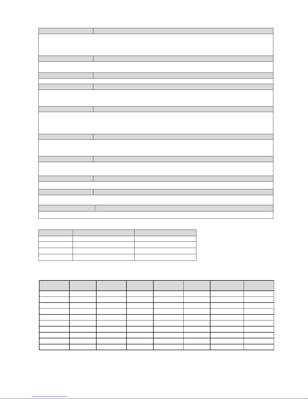
13-14
ON/OFF STAT OR OPENTHERM WATER TANK
OPTION 1: an ON/OFF therm ostat can be connected. The water heater will use the set/progr ammed tank
temperature when these terminals 13 and 14 are bridged.
OPTION 2: an OpenTherm (OT ) controller can be connected to the term inals 13 and 14. The water heater
software will detect and use this OpenTherm signal automatically.
15-16
0-10 VDC CONTROL SIGNAL
These terminals are used for an external 0-10 VDC control signal. PARAMETER: A parameter change is
needed. NOTICE: Terminal 15 [+] (positive) and terminal 16 [-] (negative).
17-18
DO NOT USE
Do not connect any cable to these connections.
19-20
LOCK-OUT OR PUMP ON/OFF
This contact is N.O. (normally open). When the unit is in lock-out this contact will close.
This contact can also be used for the switching of a pump with a separate control input connection.
(PARAMETER: A parameter change is needed).
21-22
BURNER ACTIVE OR EXTRA WATER HEATER OR PUMP ON/OFF
This contact is N.O. (normally open). When the unit starts the burner and detects the flame, this contact will be
closed. This contact can also be used to control an external (extra) water heater. This contact can also be used
for the switching of a pump with a separate control input connection.
(PARAMETER: A parameter change is needed).
23-24
BURNER DEMAND OR PUMP ON/OFF
This contact is N.O. (normally open). When the unit receives any heat demand this contact will close.
This contact can also be used for the switching of a pump with a separate control input connection.
(PARAMETER: A parameter change is needed).
25-26-27
CIRCULATION PUMP P3
This contact can be used to connect an “old type” on-off pump. (Not a high efficiency pump).
Pump is switched off, when there is no heat demand, after post running time.
28-29-30-31
EMPTY
Do not connect any cable to these connections.
32-33-34
POWER SUPPLY
The power supply connection of the unit. 32 = phase wire; 33 = ground wire; 34 = neutral wire.
35-36
EMPTY
Do not connect any cable to these connections.
7.4 Sensor values
SENSOR
SENSOR TYPE
SENSOR VALUE
S1
Internal flow sensor
NTC-10K
S2
Internal return sensor
NTC-10K
S3
Tank sensor
NTC-10K
S6
Flue gas sensor
NTC-10K
Conversion table: temperature vs. resistance for all sensors NTC-10k
Temperature
(°C)
Resistance
(Ω)
Temperature
(°C)
Resistance
(Ω)
Temperature
(°C)
Resistance
(Ω)
Temperature
(°C)
Resistance
(Ω)
-30
175203
20
12488
70
1753
120
387
-25
129289
25
10000
75
1481
125
339
-20
96360
30
8059
80
1256
130
298
-15
72502
35
6535
85
1070
135
262
-10
55047
40
5330
90
915
140
232
-5
42158
45
4372
95
786
145
206
0
32555
50
3605
100
677
150
183
5
25339
55
2989
105
586
155
163
10
19873
60
2490
110
508
160
145
15
15699
65
2084
115
443
165
130
Page 36
E93.0901EN.A Manual Consul+
36
7.5 Electrical schematics
wire
bridge
External safety device:
- External flow switch
- Smoke detection
- Gas detection
- Ventilation fan
- Flue gas fan
- End switch motor actuated
flue gas valve
- Gas leakage tester
- etc
16151413
16151413
+ 0 - 10
VDC
OpenTherm/
power stealing
thermostat
7
8 9 101211
GENERAL
BLOCKI NG
7 8 9 10 11
12
65
4
3
2
1
6
5
43
2
1
Boiler
SENSOR
Boiler sensor 10K
K8
K7
K7
K7
K1
K1
ref.1
K2
K2
K2
K4
K4
+
K9
K9
K0
K0
K3
K3
K5
K5
FAN
internal
connections
internal
connections
connection
examples
ref.1
N.C.
N.C.
gas valve(s)
ionisation and/or ignition
CN7
CN6
fan control
siphon pressure switch (PSW)
clixon/maximum (S7)
water thermostat 24vdc
flue sensor ntc (S6) 10K
return sensor ntc (S2) 10K
flow sensor ntc (S1) 10K
CN12
1413121110
9
8
76543
2
1
12
11
10
9
8
7
6
5
4
3
2
1
CN10
CN11
2
3
4
5
6
7
8
16
15
14
13
12
11
10
1
2
3
4
5
6
7
8
9
10
11
12
1
23456
7
8
9
1011121314
out
1
91718
18
17
9
110
11
12
13
14
15
1687
6
5
4
3
2
K8
K6
K2
EMPTY
On/Off Stat
or
OpenTherm
Heating
Circuit
Remote temperature
setpoint or burner input
signal form BMS
DISPLAY
CN15
K6
K8
K2
K6
K3
+24Vdc
Fan Hall
Fan PWM
K7
K6
K0
PWM pump control
K8
K0
Power PWM pump
K6
K2
K10
EMPTY
EMPTY
water pressure switch
K1
K0
EMPTY
Page 37
E93.0901EN.A Manual Consul+
37
Therm.stat 230v
When using a RCW controller:
Rewire terminal as shown
so CN5 7/8 are bridged.
Pomp 3, L'
Pomp 3, N'
K6
K2
K8
K8
Therm.stat 230v
MAINS
230VAC
343332
343332
POWER
SUPPLY
28 29 30 31
28 313029
272625
272625
19 20 21 22 23 24
242322212019
N.O. N.O.
N.O.
LOCK-OUT
HEAT
DEMAND
BURNER
BURNING
Lock-out
N.O.
Burner burning
N.O.
1817
1817
connection
examples
CN4
CN do not use
10981 2 43 5 6 71 2 43 5 6 7653 421
K5
K9
K2
K6
K3
K8
K4
K7
FUSE 2
FUSE 1
F2 F1
boiler casing
Heat demand NO
CN8
T2
Heat demand NO
CN5CN1CN3
MAINS L'
Lock-Out NO
Flame on NO
Gasvalve, N'
Gasvalve, L'
L N
L N
CH System
Pump P3
K10
Heat demand
N.O.
ignition
transformer incl.
ionisation input.
3635
36
35
HOT WATER
CIRCULATION PUMP3
(ON/OFF PUMP)
not the standard pump
CN10
FAN
K2
K6
K3
Do not
use
WIRING COLORS
K0=white K6=blue
K1=yellow K7=red
K2=brown K8=black
K3=green K9=purple
K4=grey K10=yellow
K5=orange
Lock-Out NO
Flame on NO
MAINS N'
EMPTY
EMPTY
Page 38

E93.0901EN.A Manual Consul+
38
DE CONSUL+ WATER HEATER
8.1 Water quality
In direct water heating appliances, the water flows directly through the heat exchanger of the water
heater. Because all the ti me fresh water, containing dissolved minerals , is heated, scaling may
occur. To prevent this, water quality must meet several standards.
The values are the following:
Water temperature max. = 75°C
Maximum allowed water hardness is 205 PPM or 205 mg/L CaCO
3
(= 11,5°dH)
TDS (total dissolved solids) may not exceed 450 PPM
Water hardness and TDS together ma y not exceed 450 PPM
The pH value of the water may not be under 6,5 and not above 7,5 (measured cold)
If water hardness is too high a water softening system is necessary.
If TDS alone or the combined value is higher than the abovementioned, the water should be heated
by means of an indirect water heating appliance.
Minimum water hardness = 80 PPM or 80 mg/L CaCO
3
(= 4.5°dH)
Minimum TDS = 100 PPM
Water that’s under thes e minimum values normally has a pH value which is ag gr e s s ive and c orr osive.
NEVER install a direct heated water system in an area where water quality does not comply with above mentioned values.
If the water hardness is too high, a water treatment ins tallation should be insta lled reducing the wa ter hardness
within acceptable level.
8.2 Frost protection
The water heater has a built-in frost protecti on that is autom atically activating t he pump when th e water heater
return (water) temperatur e drops below 5°C (program mable). When the water heater return temperature dr ops
below 3°C (programm able), the burner is also ignited. T he pump and/or burner will shut down as soon as the
return temperature has reached 10°C (programmable). The abovementioned temperatures are related to the temperatures measured by the tank sensor of the water heater. This frost protection function will not fire up the water
heater in case of a “general blocking” of the burner demand.
NOTICE:
- This frost protection function is only protecting the water heater and not the whole sanitary system.
- This frost protection function is only useable if water circulation through the system is possible - if
not, the water heater goes in a lock-out.
- Because it concerns a programmable setting, a water heater damaged by frost is not covered un-
der warranty.
8.3 Legionell a program
To avoid contamination of the water with Legionnaires’ disease, a special anti-Legionella program is present in the
software of the water heater control, the settings of which are freely programmable.
NB! This option is default turned ‘OFF’, the responsibility for a Legionella-free installa tio n lies with the en d-user.
See § 11.2.2 on page 72 for an extensive explanation of how to use this option.
Page 39

E93.0901EN.A Manual Consul+
39
8.4 Flow monitoring
Flow
In the control of the water heater an extensive flow monitoring function has been implemented. If the temperature
difference between incoming cold water and outgoing hot water gets too high, this indicates a too small water flow
through the appliance.
Safety actions
- If the temperature diff erence exceeds the max imum at a certain l oad, for a long er time than s pecified i n the
software, the displa y will show ‘Delta direct block’ and the appliance w ill block: it switches imm ediately to
reduced power. Po wer is th en s l o wl y inc r eased t o the required level ag ain . T he f ourth time, so af ter t hr ee of
these blockings, the water heater will go in lock-out (F16) and the display shows ‘FlowReturn dT fault’.
-
At very bad flow rates (tem perature diff erence for 10 s econds ex c eed ing a c er tai n entered s af ety v alu e), the
appliance will skip the blockings and immediately go in lock-out: F16, display ‘FlowReturn dT fault’.
- In Service mode the appliance will immediately go in lock-out when the maximum value corresponding to the
applied power is exceeded, skipping the blocking procedures that apply at normal operation. Again F16, display ‘FlowReturn dT fault’.
NB! All values of this flow monitoring have been programmed by EHS to get the best performance combined with
a long-life time.
8.5 Water pressure switch
Water pressure get ting too low indica tes a blocking of the water flow. If that is t he case, heat from t he f lu e ga s es
cannot be transferred and will flow away thr ough the flue gas c hannels. Also ove rheating of the heat ex changer
and/or other parts of the system could occur, if no measures would have been tak en. For this reason a water
pressure switch, WPS, has been integr a ted in al l CONSUL+ system models.
Operating values
The water pressure s witch has one Norm ally Open (NO) contact, m eaning the contact is o pen in rest position
when no pressure is applied. As soon as the system has been filled and the pressure exceeds 0.85 bar, the switch
closes, enabling operation. If, by any cause, the pressure drops below 0.75 bar, the system will be blocked.
In this case the display will show:
Display message
W a t e r p r e s s u r e f a u l t 9 9 9 , 5 h r
s
Reason
Water pressure is too low or high.
Check if there is any leakage or maybe the pressure in the service pipe has dropped down.
See also § 16.2 ‘Blocking codes’, from page 90 on.
Page 40
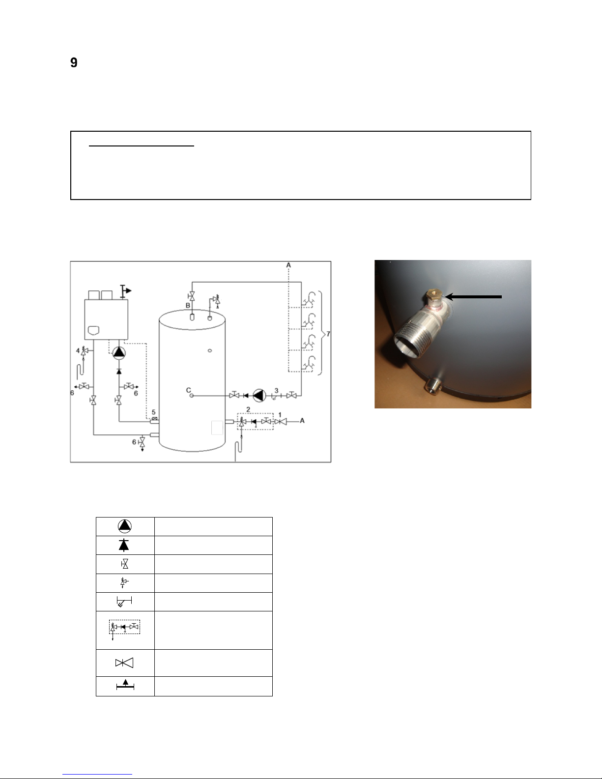
E93.0901EN.A Manual Consul+
40
THE CONSUL+ SANITAIRY SYSTEM: INSTALLATION INSTRUCTIONS
9.1 The CONSUL+ system
The system is set up as sh own in the next example sho wing a com bination of a water heat er and a tank. Other
combinations are possible as well. Contact your supplier regarding cascading possibilities.
SAFETY COMPONENTS
NB! The pictures in §§ 9.1.1 and 9.2 show examples of f unctional insta llations. T he safet y components as
shown in these pictures are NOT necessarily conform all applicable standards and regulations.
ALWAYS have the installation installed by a skilled installer. Safety must be added according to all applicable
standards and regulations.
9.1.1 STAND-ALONE SET-UP
The basic form of a CONSUL+ installation is one water heater with one tank.
Shown in the picture are the principle components and connections.
Po
sition tank sensor on ECO tanks
Tank sensor: see § 9.2.1 on page 35.
E
xample of a combination of one water heater and one tank
Extra explanation:
1) P
ressure relief valve ( mandatory in case ser-
vice pipe pressure is too high)
2) Inlet combination with valve (mandatory)
3) Apply filter if necessary (recommended)
4) A suitab le safety val ve must be m ounted near
the water heater (mandatory)
1
T
his safety valve ma y never be isolated from
the water heater by means of a ball valve
5) Mount remote tank sensor in the screw hole on
the return pipe (see picture) (necessary)
When screwing is not possible, mount the tank
sensor on the retur n pip e as c lose as poss ible
to the tank
2
6) D
rain valve (recommended)
7) Hot and cold water mixers
A) Cold water inlet (service pipe)
B) Hot water supply circulation
C) Circulation return
PUMP
NON-RETURN VALVE
VALVE
SAFETY VALVE
FILTER
INLET COMBINATION
- Overflow
- Controllable return valve
- Valve
PRESSURE REGULATING
VALVE
Manual Air vent.
Page 41
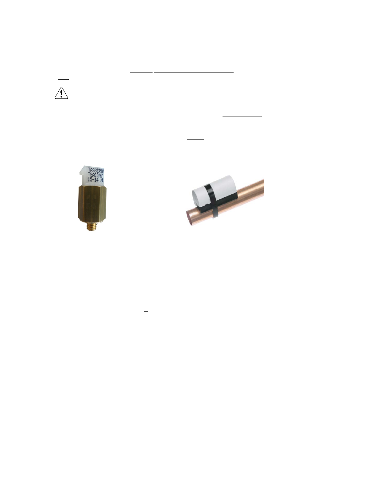
E93.0901EN.A Manual Consul+
41
9.2 Control
9.2.1 TANK SENSOR
With the Consul+ water heater, a threaded sensor or Strap-on pipe sensor is supplied as tank sensor.
On a new ECO tank, this threaded sensor can be mounted on the return pipe right away.
The use of this threade d se nsor is als o rec ommen ded for existing tank set-ups, because its controlling behavior is more stable than that of the strap-on pipe sensor.
When this threaded sensor is used on an existing ECO tank set-up, a reducing nipple may be needed, to be able
to mount the sensor on the return of the tank , provi ded th at th is retur n h as a thre aded sock et, i. e. this ECO tank
is not older than from 2008.
On other tanks, generall y the supplied threaded sensor cannot be applied; the existing pipe sensor mus t be kept
in use and be connected to the water heater c ontro l. Check that this sensor has been p laced on one tank retur n,
as close as possible to this tank. Or use an immersion tank sensor NTC 10kohm.
E04.016.677 Threaded sensor (M5x5) with Molex connection.
E04.016.304 Strap-on pipe sensor.
• Supplied with the water
heater, cable with Molex
connector included.
• Available including connect-
ing cable.
9.2.2
GENERAL CONTROL
There is no need for a sensor in the tank, becaus e when the pump starts to run, the tank sensor of the
water heater is measuring the water temperature of the tank.
When no water is drawn from the tank, the tank sensor is measuring the water temperature in the tank.
After ending a heat demand, the pump has a post turning time.
On the control panel, the tank or hot water temperature can be set.
When an RCW remote wall controller is connected to the wire t erminal (13) and (14), the s etting of the
tank temperature can be done with this controller (Open Therm bus), also the night or weekend reduction
of tank temperature.
During a period of no ta pping, the tem perature inside the tank is m aintained at th e Setting tem perature
automatically.
A safety control stops the water heater from firing, when the tem perature difference between flow and
return gets higher than allowed at the actual load (flow monitoring (ΔT function)).
Parameters: the default of the parameters of the water heater control have been set for this type of tanks.
Page 42
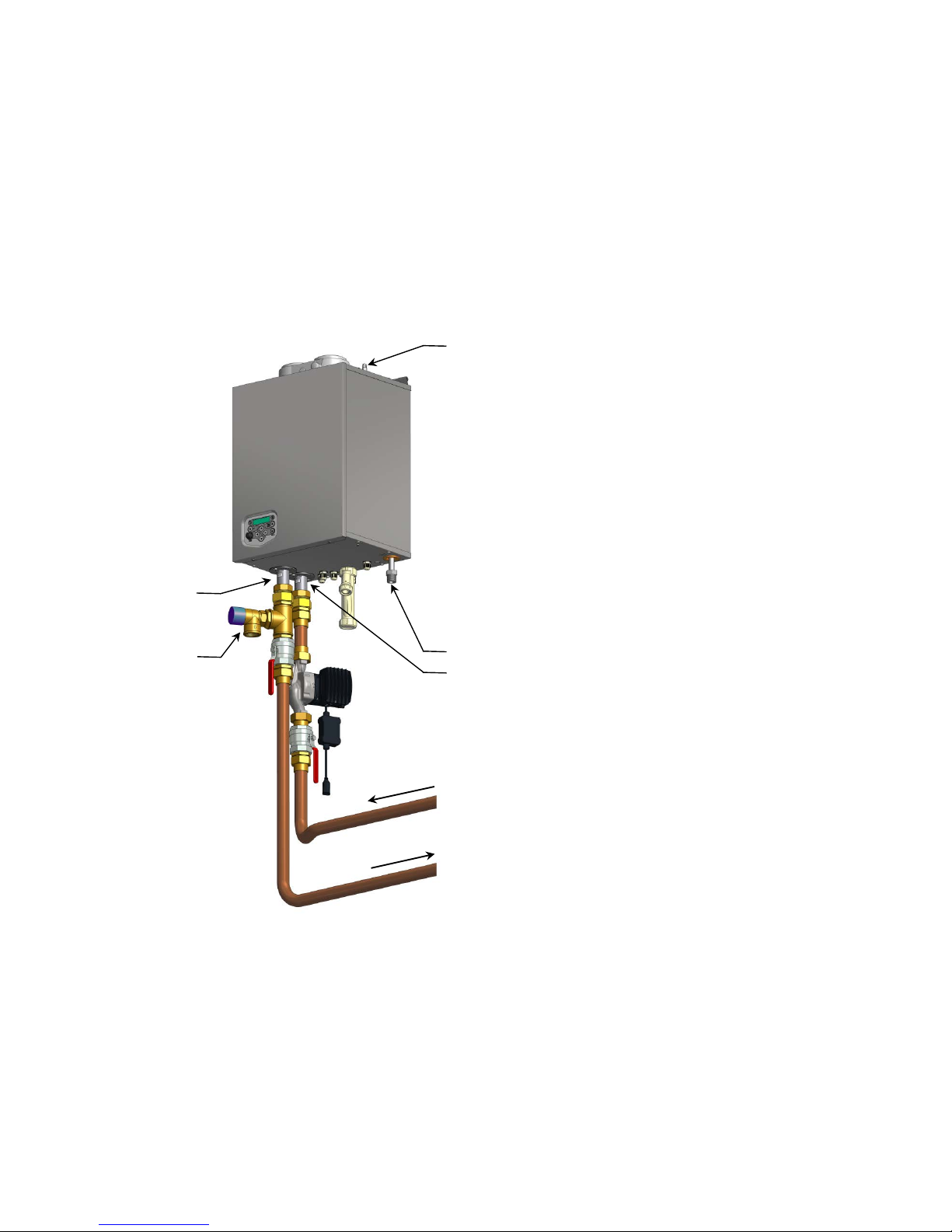
E93.0901EN.A Manual Consul+
42
9.3 Water heater and tank: connections and connection sizes
9.3.1 CONNECTING THE TANK TO THE WATER HEATER
• Connect the pump b y means of couplings and a piece of copper pipe to connection A of the water heater
(note the flow direction of the pump).
• Connect both pum p cables (Power supply and contro l) to the right pump connec tors. Cables are located at
the bottom of the heater (Strapped with a ty-rap)
• Connect the inlet of the pump to the upper of the two close above each other located connections of the tank,
labelled ‘return to water heater’.
• Connect connection B of the water heater to the lower of the two close above each other located connections
of the tank, labelled ‘flow from water heater’. Also, make a tap point in this line at the lowest point.
WATER HEATER CONNECTIONS
A = inlet cold water
B = outlet hot water
C = overpressure safety valve
D = gas
E = Manual air vent
B
C D A
E
Page 43

E93.0901EN.A Manual Consul+
43
9.3.2 CONNECTING THE TANK TO YOUR DHW INSTALLATION
(See picture on next page →)
• Connect the fresh water supply to the single connection C, labelled ‘cold in’, opposite to A and B which were
used for connecting the water he ater. For t he applic ation of in let com binati on, ( control) val ves, etc. all a pp licable regulations should be met.
• Connect the DHW connection on top of the tank, labelled ‘hot out’, to your DHW installation.
• Connect the recirculation line to connection F, labelled ‘circulation return’, on the side of the tank, at the same
height as inlet C.
The EHS tanks have the following DHW connections:
• COLD IN for inlet of fresh water
• HOT OUT for outlet of DHW
• water heater return for connection to inlet of water heater
• water heater flow for connection to outlet of water heater
• CIRCULATION RETURN for recirculation of DHW from installation to tank
There are also connections for:
• Thermometer (on the side at ± ¾ of height of the tank)
• Connection for T&P valve ( mounted on top) ac cording to the applica ble standar ds and regul ations. Eve n
if a T&P valve must be applied, the safety at the water heater’s side, on position C (← see previous page),
should be maintained at all times.
Tank connection sizes:
Code Connection M / F Remarks EWD150 EWD230 EWD300 EWD450 EWD750
A
return to water
heater
M
incl. reducing ring
-
-
R 2"
R 2"
R 2"
excl. reducing ring
R 1"
R 1"
R 1½"
R 1½"
R 1½"
B
flow from water
heater
M
incl. reducing ring
-
-
R 2"
R 2"
R 2"
excl. reducing ring
R 1"
R 1"
R 1½"
R 1½"
R 1½"
C
cold water inlet M
incl. reducing ring
-
-
R 2"
R 2"
R 2"
excl. reducing ring
R 1"
R 1"
R 1½"
R 1½"
R 1½"
D
DHW outlet M
incl. reducing ring
-
-
R 2"
R 2"
R 2"
excl. reducing ring
R 1"
R 1"
R 1½"
R 1½"
R 1½"
E
free connection
(T&P valve)
F incl. plug Rp1½" Rp1½" Rp 1½" Rp 1½" Rp 1½"
F
circulation return M incl. cap R ¾" R ¾" R ¾" R ¾" R ¾"
G
bleed valve - - - - - - -
H
thermometer
connection
F incl. plug Rp ½" Rp ½" Rp ½" Rp ½" Rp ½"
Page 44
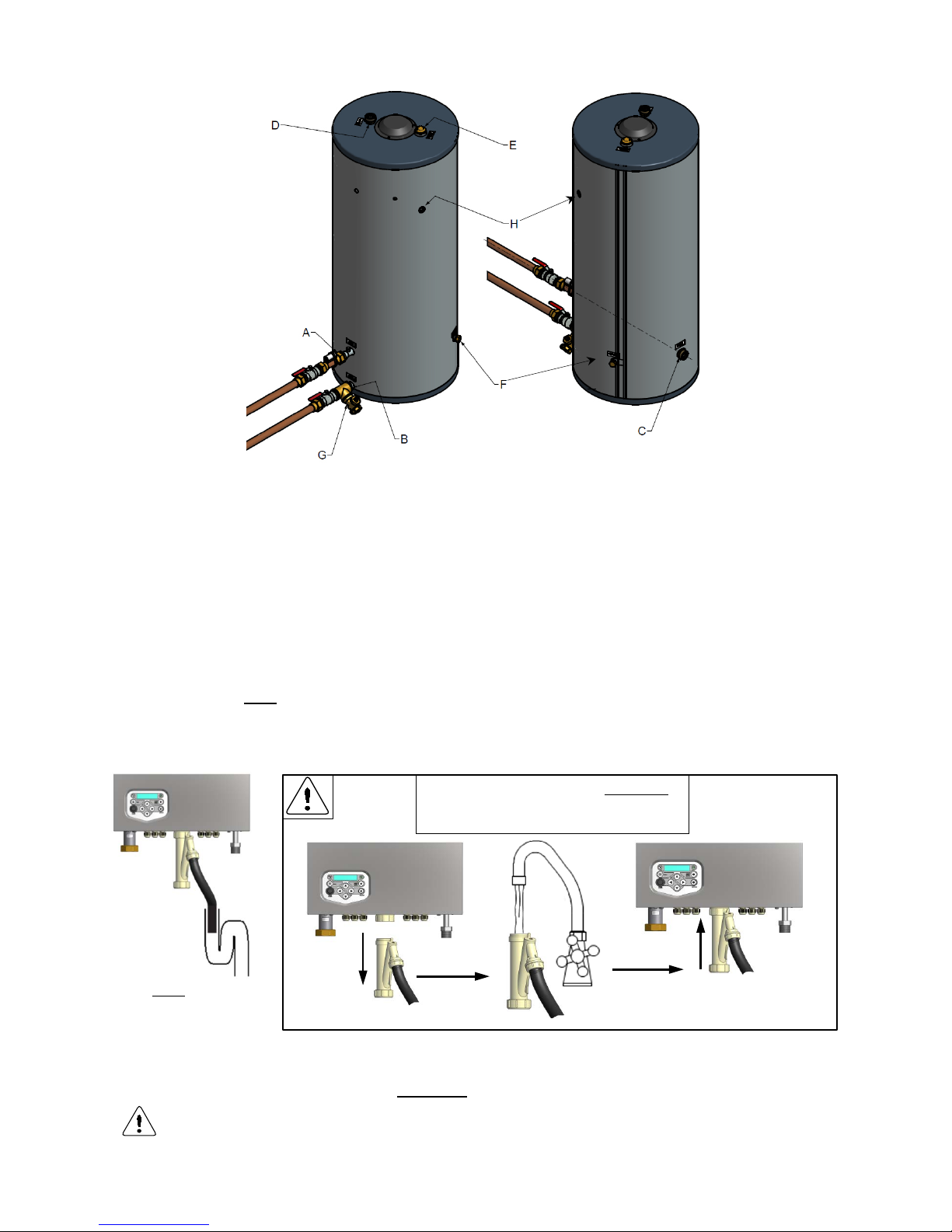
E93.0901EN.A Manual Consul+
44
9.3.3
CONDENSATE DRAIN CONNECTION
The condensate drain is p l ac ed at t he center at the bottom of the water heater and has a ¾ inch hose disc ha r ge.
Connect this flexible hose to the sewer system.
Use only plastic parts with the condensate drain. Metal lines are not allowed.
Blockage of this drain might damage the water he ater. T he drain connect ion is co rr ect when the con densat e can
be seen flowing away, e.g. using a funnel. Any damage that might occur, when the drain is not installed correctly,
is not covered by the warranty of the water heater.
There should be an open connect ion between the co ndensate hose and t he sewage system , to make sure that
any pressure differenc e between the t wo can nev er af fect the c ondens e water lev el and henc e the f unctionin g of
the water heater:
open connection
When mounting the bottom part of the siphon, before c ommissioning the water heater and/or after
maintenance, it must ALWAYS be completely filled wi th wat er.
This is a safety measure: the water in the siphon keeps the flue gases from entering the plant
room via the condensate drain.
The siphon must ALWAYS be completely
filled with water to the edge before placing
back on the unit
Page 45
E93.0901EN.A Manual Consul+
45
9.3.4 PIPE LENGTH AND DIAMETERS.
When the water heater and tank are sep arated over som e distance, the inter connecting pi pes may only have a
certain maximum length, d ependen t of the n um ber of bends and th e lik e com ponents. For ever y applied component, a so-called ‘equivalent length’ is deducted from the total allowed.
Equivalent length:
- Length of the connecting pi pes from the water heater ’ to the t ank ma y not exceed a cert ain meas ure.
Components, such as bends and the l ike, contribute to the total length by their so-called ‘equivalen t
lengths’.
- To achieve the new maximum length, th e equivalent lengths of the applied components m ust be de-
ducted from the allowed length without components (first column of the table).
General remark: diam eters may never be c hosen smaller than sp ecified in the tables; f low must remain
guaranteed.
Diameter copper pipe
mm
35x1,5
42x1,5
maximum straight length C35 flow and return
Consul+35
m
163,5
439,6
maximum straight length C55 flow and return
Consul+55
m
60,2
162,0
equiv. Length 90⁰ knee R=0,5xD
Consul+35 & 55
m/knee
1,6
2,0
equiv. Length 90⁰ knee R=1xD
Consul+35 & 55
m/knee
0,8
1,0
equiv. Length 45⁰ bend R=1xD
Consul+35 & 55
m/bend
0,6
0,7
equiv. Length fully ported ball valve
Consul+35 & 55
m/valve
0,3
0,4
Tanks
equiv. Length tank EWD 150/230
Consul+35
m/tank
36,5
98,1
equiv. Length tank EWD 300/450/751
Consul+35
m/tank
7,3
19,6
equiv. Length tank EWD 150/230
Consul+55
m/tank
33,5
90,0
equiv. Length tank EWD 300/450/750
Consul+55
m/tank
16,7
45,0
Example calculation:
A project has following specification:
A Consul+55 with tank type EWD300. Also 2 x 90⁰ bend R=0,5xD and 2 x fully ported ball valve, and copper pipe
35x1,5 mm must be used
According the table the maximum available pipe length between tank and Consul+ is 60,2 m (Return and Flow)
Equivalent length of the tank type EWD300 is -16,7m (regarding a Consul+55).
Equivalent length of both bends 2 x 90⁰ R=0,5XD is 2 x -1,6 = -3,2m
Equivalent length of both fully ported ball valves is 2 x -0,3 = -0,6m
Total equivalent length is -16,7 -3,2 - 0,6 = -20,5 m.
Available length Return and Flow = 60,2 – 20,5= 39,7m
So, distanc e between Consul+ and Tank is always smaller as 39,7 / 2 = 19,8 meter (Be aware of the ver tical
pipes).
The applied pump m ust be contr olled onl y b y the Cons ul+ water h eater control . If, f or an y reason, an
external pump control is applied w ithout written a pproval of EH S, then the c omplete warran ty on the
Consul+ water heater and all delivere d parts will beco me invalid.
Page 46
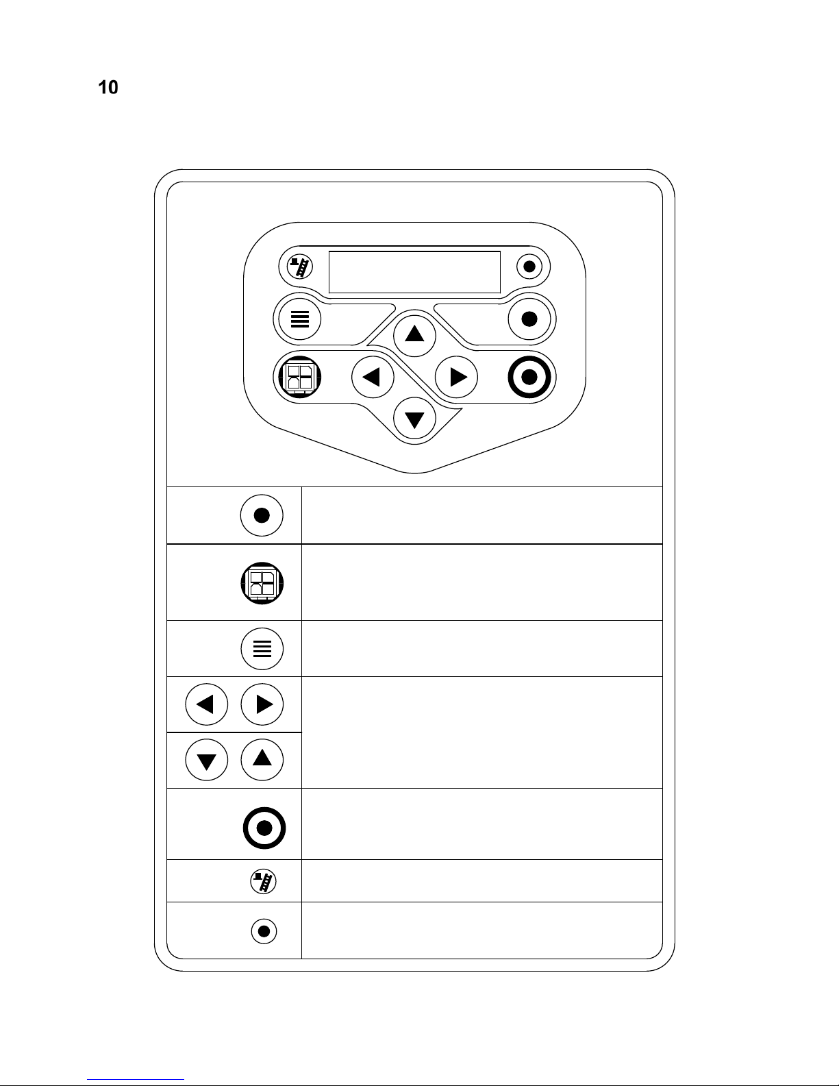
E93.0901EN.A Manual Consul+
46
USER INTERFACE
10.1 Control panel / display unit
DISPLAY
2 rows / each 20 characters
MENU
ON/OFF
RESET
ENTER
SERVICE
COMM. PORT
ON/OFF
RESET
ENTER
Press and hold for three seconds for stand-by/progr. mode
Press and hold for six seconds to switch boiler on/off.
Used as RESET and ENTER button when programming.
Connector for connecting computer cable.
Buttons can be pushed to open menu
[ hold for one second].
Buttons to toggle through measured temperatures.
These are also used for navigating through the menus and
used for changing values.
Button to activate service function.
[ hold for three seconds].
Schornsteinfeger function (only for Germany).
Light: will light up when controller sees good flame signal.
Lights when burner is burning.
SERVICE
MENU
COMM. PORT
Page 47
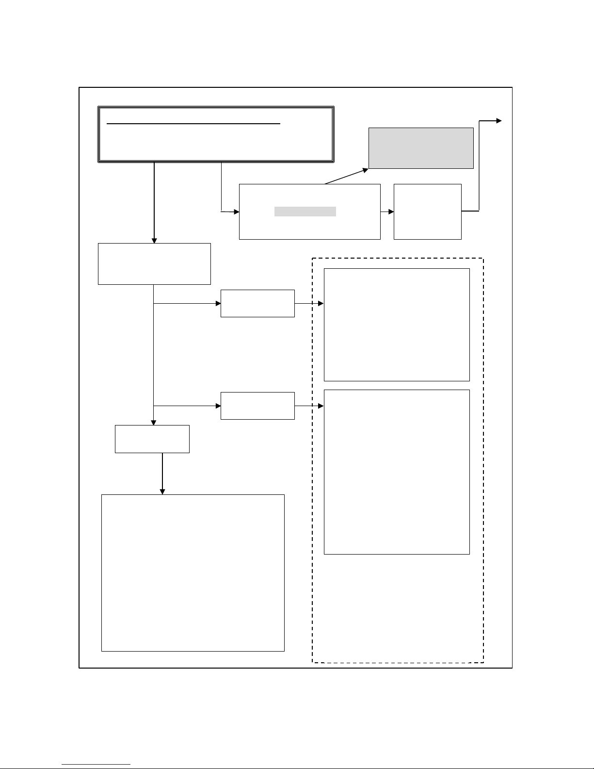
E93.0901EN.A Manual Consul+
47
10.2 Control panel menu structure
NOTICE: Pressing too
long will switch off the
water heater.
BASE SCREEN : (appears during operation)
WTRHTR : No demand / Sta ndby / burning
> > > : 1 1 8 ° C ( 1 2 5 ° C )
1. view data
press: ◄►
"MONITOR" screens
One can toggle through the measured values and status of the heater.
Pressing "ON/OFF, RESET, ENTER" briefly
will cause the display to go back to the base
menu.
When no button has been pressed for three
minutes the display will automatically go to
the BASE DISPLAY.
(This period can be set by a parameter).
Display shows 2x20 digit message for three seconds.
Message can be set in parameters.
example:
Company name
City, Country
press: ▲
Display shows for three seconds:
- Heater type
- Time, date and day
example:
Z-FG 550 13:51 US (or EU)
06 / 01 / 2010 Wed
After this message the display
shows for three seconds:
- Software version and
- Cascade designation
example:
Firmware : Mk 00197
Address : 0
press: ▼
These three messages will also
show when:
- Heater is connected to the power
- When heater is turned ON
- When heater is turned OFF
sequence:
The messages will show from
TOP to BOTTOM each for three
seconds.
press: MENU
1
2
2. press [ON/OFF] for
± three seconds to
programme in standby mode
Page 48
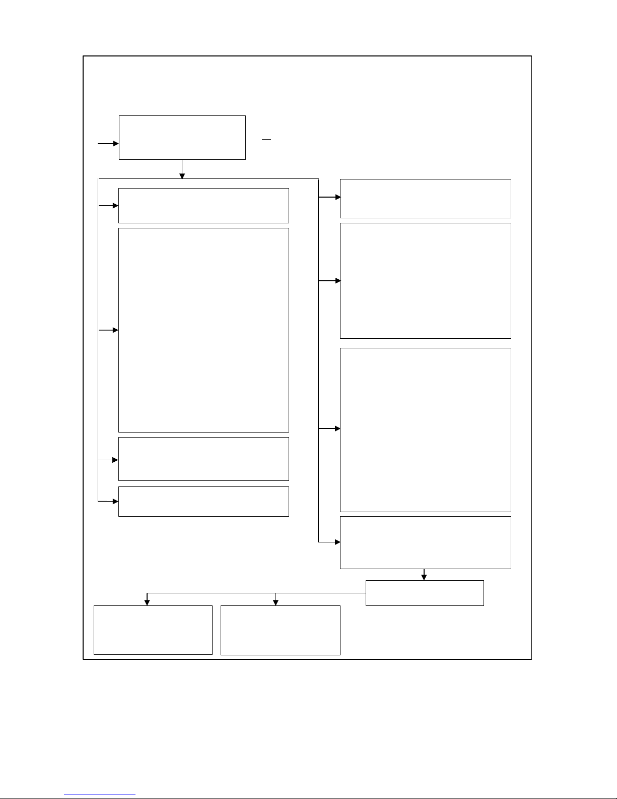
E93.0901EN.A Manual Consul+
48
By pressing (◄ ►) one can
toggle though the available
menus.
"USER LOCK" menu
In this menu one can lock the menu for
users
0= UNLOCKED
1= LOCKED
When un-locked the user can enter the
"MENU" by pressing the menu
button and all submenus will show.
When locked the user has to push the :
MENU and simultaneously
press ▼ for five seconds to get access
to all submenus.
This is to prevent accidental changes!
NOTE: The parameters sub menu can
always be accessed.
"MAINTENANCE" menu
By pressing (◄ ► ) one can set the
following options:
- Maintenance reset
- Maintenance Mode
- All
- Date
- Ignition cycles
- Burning hours
- Mainten Off
"SETPOINT" menu
In this menu one can change temperature settings without the need for a
password.
- Hot water set point
Calorifier or Water heater (depends on
heater type)
- Hot water reduced
The amount of degrees diff. relative to
"Hot water set point" during night reduction.
- Local set point water heater
The temperature of the hot water supply from the DHW appliance
to the tank is set here.
"PROGRAM" menu
In this menu one can set the DHW and
Anti Legionnella program.
"OPERATING HISTORY" menu
Shows burning hours DHW, etc.
"FAULT HISTORY" menu
press: ▼ Reading last ten faults (only
reading!).
"TIME/DATE/DAY" menu
In this menu one can set the time and
"PARAMETER " menu
In this menu one can change parameters. The possible access
depends on the password that is used.
HOW TO CONFIRM CHANGES
When changes have been made in one of the nine menus below, the
user presses ENTER to confirm these changes.
To prevent anyone from making changes by mistake, the following
happens when changes are made:
Step 1: The user presses [ENTER] to confirm the change made
or [MENU] to exit the menu without changes. HINT: First programme
all changes planned, then only after that, press [ENTER]
Step 2: The display asks the user to be sure to make these changes.
The user can cancel or confirm by using the left and right arrows.
CANCEL =
◄
CONFIRM =
►
Enter password
Enter PW Level 1:
three second message
confirming access:
LEVEL 1
Enter PW Level 2:
three second message
confirming access:
LEVEL 2
parameter menu
Page 49
E93.0901EN.A Manual Consul+
49
10.3 Display during operation
During normal operation, the text in the display shows the status of the water heater. In the following
graphs the several displays during normal operation are explained.
Display at WATER HEATER / HOT WATER DEMAND
Heat demand type:
Actual status:
W A T R H T R : S T A N D
- B Y
> > > : 1 2 3 . 4 ° C ( 1 2 3 . 4 ° C
)
cascade
communication indicator
setpoint water temp.
temp. measured by tank
sensor.
Can be turned off by P5 BJ
Explanation "Actual status" screen
Actual status:
B o i l e r o f f
When water heater is switched off (only text in the display during this status).
N o d e m a n d
No heat demand signal coming from the room thermostat and tank sensor
(open).
S t a n d
- b y
Room thermostat & tank sensor/thermostat detect heat demand but set point
is reached.
P r e
- p u r g e
The fan is purging before a burner start attempt.
P r e
- i g n i t i o n
Ignition starts before opening of the gas valve.
I g n i t i o n
The igniter is igniting.
P o s t - p u r g e
The fan is purging after burner is switched off.
B u r n i n g 1 0 0
%
When the burner is firing, also the actual rpm% is shown.
Explanation "Cascade communication indicator"
NO CASCADE COMMUNICATION
> > >
no.1
Always showing the fixed ">>>"
CORRECT CASCADE COMMUNICATION
> >
no.1
no.2
>
Showing alternating no.1 & no.2 with one second interval.
Page 50
E93.0901EN.A Manual Consul+
50
10.4 Monitor screens
During normal operation and standby, the [◄] and [►] buttons can be used to show some water heater information,
including measured t emperatures, settings an d data. In the following graphs is explained wh ich values can be
shown at the display. When no button is activated for three minutes, the display will return to its status display.
Pressing [◄] or [►] while being at the "operating screen" toggles through the screens below.
When pressing [ON/OFF, RESET, ENTER] or [MENU] at any time the display returns to the base menu.
SCREEN: 1
T 1 F l o w 1 2 3 , 9 °
C
Measured value by the internal flow sensor.
T 2 R e t u r n 1 2 3 , 9 ° C
Measured value by the internal return sensor.
O p e n
Shown when controller doesn’t detect this sensor.
S h o r t e d
Shown when sensor wires or sensor itself is shorted.
SCREEN: 2
T 3 E x t e r n a l 1 2 3 , 9 ° C
Measured value by the external sensor.
T 4 C a l o r i f i 1 2 3 , 9 ° C
Measured value by the tank sensor.
O p e n
Shown when controller doesn’t detect this sensor.
S h o r t e d
Shown when sensor wires or sensor itself is shorted.
SCREEN: 3
T 5 O u t d o o r 1 2 3 , 9 °
C
Measured value by the outdoor sensor.
T 6 F l u e 1 2 3 , 9 °
C
Measured value by the flue gas sensor.
O p e n
Shown when controller doesn’t detect this sensor.
S h o r t e d
Shown when sensor wires or sensor itself is shorted.
SCREEN: 4
d T F l o w R e t u r n d T F l u e R e t u r
n
1 2 3 , 9 ° C
Temp. difference between internal flow & return.
1 2 3 , 9 ° C
Temp. difference between flue gas & internal return.
SCREEN: 5
Temp. difference between external & internal return
(ΔT LLH).
d T E x t R e t u r n 1 2 3 , 9 ° C S i g n a l P o w e
r
External supplied 0-10 Volt dc signal.
S e t p o
i
"Power" = power input control or "Setpoi" = set point
control.
SCREEN: 6
F a n s p e e d 9 9 9 9 r p m
Actual fan speed in rpm.
F a n s p e e d 1 0 0
%
Actual fan speed % of maximum allowable fan
speed.
The maximum actual rpm may be lower than the maximum rpm set point. The fan may not be able to reach the maximum rpm set point,
because of the unit’s resistance, which is still correct according to its design.
SCREEN: 7
F l a m e s i g n a l 1 0 0 μ
A
Flame signal given in μA.
W a t e r P r e s s u r 1 , 0 b a
r
Shows water pressure when sensor is connected.
SCREEN: 8
P u m p 1 H e a t e r O f
f
Pump 1 (HEATER PUMP) On or Off.
P u m p 1 S i g n a l 1 0 0 %
Modulating signal Pump 1 in (%).
SCREEN: 9
P u m p 2 C a l o r i O f f
Shows when the calorifier pump is "ON" or "OF".
3 - w a y V a l v e H e a t i n g
Signal to the 3-way valve: "HEATING" or "HOTWATER".
SCREEN: 10
P u m p 3 S y s t e m O f
f
Shows when the system pump is "ON" or "OF".
h h : m m D D / M M / Y Y Y Y D a
y
hh=hour; mm=minutes; DD=day; MM=month;
YYYY=yr; Day of the week
Page 51
E93.0901EN.A Manual Consul+
51
SCREEN: 11
C a s c D e s i g n 0
0 = MASTER, 1 ..... 11 = SLAVES
C a s I n f 0 1 2 3 4 5 6 7 8 9 A
B
Displays number, priority and state of cascade water heaters.
DESCRIPTION "CASCINFO" Screen 11
Shows the number of water heaters connected with the cascade. T he master/lea d water heater is desi gnated
as 0. Slave/lag wa ter heater s will be des ignated 1, 2, 3, 4, 5 , 6, 7, 8, 9, A, B. W hen a “-“ is used instea d of a
number, then that water heater is either not connected, or in a lockout mode and not available for the cascade.
When an “x“ is used instead of a number, then that water heater is connected, but in lockout mode.
When the number is f lashi ng, th en that water h eater is prov iding heat t o the c asca de. W hen the lead ing water
heater is changed according to the set priority change time, then that water heater’s address will be shown first
in the row of numbers.
Example 1: "3 4 5 - - - - - - 0 1 2"
There are six water heaters present and nr. 3 has priority.
Example 2: "3 4 x - - - - - - 0 1 2"
There are six water heaters present and nr. 3 has priority. Water heater 5 is present, but in a lock-out.
SCREEN: 12
C a s c P o w e r 9 9 9 % 9 9 9
%
% heat demand of total (cascade) power available (%).
D u a
l B u r n e r :
N o
One heat exchanger equipped with two burners: "Yes" or
"No".
SCREEN: 13
M a x T h e r m O p e n
Status of the maximum thermostat: "Open" or "Closed".
G e n B l o c k C l o s e
d
Status of the general blocking contact: "Open" or "Closed".
SCREEN: 14
S i p h o n p r e s s C l o s e
d
Status of the siphon pressure switch: "Open" or "Closed".
N R V C o n t a c t
O p e n
Status of the non-return valve contact: "Open" or "Closed".
* REMARK at screen 14: No NRV used in this type of heater.
Page 52
E93.0901EN.A Manual Consul+
52
10.5 Service function
The following graphs describe how to use the service function.
Operating screen:
W A T R H T R : S T A N D - B Y
> > > : 1 2 3 . 4 ° C ( 1 2 3 . 4 ° C
)
Press [SERVICE] and hold for 3 seconds.
The burner will start and show the display below.
Operating screen:
W A T R H T R : S e r v i c e 2 6
%
> > > 7 5 . 0 ° C ( 6 0 . 0 ° C
)
"WATRHTR": It is an appliance for DHW.
"Service": It is operating in service mode.
"26%": The burner is firing at 26%.
"75,0°C": Max. allowable water temp. during service.
"60,0°C": Actual measured water temp. (when P5BJ active).
Press [SERVICE] to exit. The unit will go to the operating screen.
Press 3 s. [ON/OFF] to exit. The unit will be switched off.
By using the [▲] & [▼] buttons the burner firing rate% can be
changed.
Press [MENU] to access the main menu.
Press [MENU] to return to the service menu.
Use [◄] & [►] buttons to browse through the monitor screens.
Press [MENU] to go to the operation menu of the service mode.
Press [SERVICE] to exit the service mode.
The unit will return to the standard operation display.
Page 53
E93.0901EN.A Manual Consul+
53
10.6 Schornsteinfeger function
The purpose of this function is to have an easy interface for the "Schornsteinfegers" in Germany, to be able to do their required testing on the water
heater. This is a simplified function similar to the normal service function of
the water heater. The standard factory setting for this function is “OFF”.,
use parameter P5BK to set this function to on.
When the "Schornsteinfeger" button is pressed for 3 seconds:
the heater will fire at minimum firing rate (%)
In this state the display shows:
F l u e s e r v i c e m o d e
P o w e r : M i n i m u m
When the button is pressed (briefly) again:
the heater will fire at 50% firing rate
In this state the display shows:
F l u e s e r v i c e m o d e
P o w e r : 5 0 %
When the button is pressed (briefly) again:
the heater will fire at maximum firing rate (%)
In this state the display shows:
F l u e s e r v i c e m o d e
P o w e r : M a x i m u m
When the button is pressed briefly again: the heater will return to
the normal operation mode.
The "Schornsteinfeger" function is switched off.
NOTES:
When the heater is burning during Schornsteinfeger function
(when top display line shows "Flue service mode") and no button
is pressed for 12 minutes, the water heater will return automatically to the normal operation mode. The "Schornsteinfeger" func-
tion will be switched off.
The "Schornsteinfeger function" can be activated for the user by
programming a parameter (P5 BK)
All regular temperature safety controls remain active and the water heater pump and system pump are running.
Page 54
E93.0901EN.A Manual Consul+
54
10.7 Programming in standby mode
Standby
Use the standby mode for modifying water heater settings without interaction with the water heater control.
Changes are effectuated by leaving standby mode.
Properties of standby mode:
• Keys are active and the menu is accessible.
• Burner does NOT respond to an external heat demand.
• All control functions are ON: pumps, fans and cascade are operational, recirculation and frost protection
are active.
How to program the w ater heater:
• Disconnect or shut down the DHW thermostat and/or other external controllers from the water heater.
The pump and fan will stop after a short time.
• Switch the water heater in standby mode by pressing [ON/OFF] for three seconds.
• The next display screen should appear:
Display message
W A T R H T R : b o i l e r o f f
> > > : 1 2 3 . 4 ° C ( 1 2 3 . 4 ° C
)
• Program the water heater at the control panel (see the following sections).
• HINT: First program all changes planned, then only terminate programming mode by pressing [MENU],
or [ENTER] and NO ◄ or YES ►.
• Reactivate the water heater by pressing [ON/OFF] for three seconds again.
10.8 Setting the time & date
The following graphs describe how to program the time and date of the unit.
Operating screen:
W A T R H T R : b o i l e r o f f
> > > : 1 2 3 . 4 ° C ( 1 2 3 . 4 ° C
) Press [MENU]
Main menu screen:
M a i n M e n u
C l o c k
The display shows "CLOCK" press [ENTER]
Setting Time and Date:
S e t t i m e / d a t e 0 8 : 3 3
3 0 / 0 3 / 2 0 1 0 T u e
The day is now blinking/selected and can be changed.
Use [▲] & [▼] to change the value.
Use [◄] & [►] to select another value.
Press [ENTER] for the confirmation screen after all changes
are done.
Confirmation screen:
A r e y o u s u r e
< C a n c e l ; > C o n f i r m
Press [◄] to cancel the changes made (display goes back to
operating screen).
Press [►] to confirm the changes made. The time and day will
start blinking for a few seconds. After this, the display returns to
its operating screen.
Page 55
E93.0901EN.A Manual Consul+
55
10.9 Set points
The following graphs describe how to program the hot water set points.
BE AWARE:
The value set at “Heating
Setpoint” has to be equal
or higher as the value set
at “DHW Setpoint”
“Heating Setpoint” sets
the maximum possible
flow temperature of the
heater (The maximum
temperature of the water
to the tank).
Operating screen:
H E A T I N G : b o i l e r o f f
> > > : 1 2 3 . 4 ° C ( 1 2 3 . 4 ° C
)
Press [MENU]
Main menu screen:
M a i n M e n u
S e t p o i n t s
Select "Set points" using [◄] & [►] and press [ENTER]
By pressing [◄] & [►] the following screens can be selected.
By pressing [▲] & [▼] the blinking values in the selected screen
can be changed.
Press [MENU] to exit. The unit will reset and return to the operating screen.
Press [ENTER] for confirmation screen when all the changes are
made.
Confirmation screen:
A r e y o u s u r e
< C a n c e l ; > C o n f i r m
Press [◄] to cancel the changes made (unit will reset).
Press [►] to confirm the changes. The value set in the screen
when pressing enter will be shown for a few seconds. After
this the display returns to the normal operating screen.
Heating set point normal/day time: (parameter P4 AA = 1/2)
D H W s e t p o i n t
6 0 ° C
This is the water temperature set point that is active during the
programmed DHW periods.
DHW set point reduction: (parameter P4 AA = 1/2)
D H W R e d u c e
0 ° C
The reduction of the normal/day time set point. This reduction
is used outside the programmed DHW periods.
DHW setpoint reduction:
(parameter P4 AA = 2 and P5 DJ&DK =1)
H e a t i n g
s e t p o i n t
7 0 ° C
This parameter is the local setpoint of the water heater and is
regulated on sensor S1
(parameter P4 AA = 2, P5 DJ = 1 and P5 DK =1 ).
Page 56
E93.0901EN.A Manual Consul+
56
10.10 Setting the time r pr ograms
Two different programs can be set with the water heater, these are:
• DHW program
• Anti-Legionnaires’ dise ase ( pas teuri zation) program
START PROGRAMMING
Three programmed periods each day can be set (period 1, 2 and 3). During this period the unit will use
the normal DHW set point. Outside the programmed period(s) the unit will use the reduced temperature
as set point. When no time is programmed for a period, it will not be used.
(Example no time programmed in period 3 on Monday > "Mon 3 --:-- ---:--").
Operating screen:
W A T R H T R : b o i l e r o f f > > > : 1 2 3 . 4 ° C ( 1 2 3 . 4 ° C
)
Press [MENU]
Select "Timer" using [◄] & [►] and press [ENTER]
Main menu screen:
M a i n M e n u
T i m e r
Press [ENTER]
Setting program times:
P r o g r a m C H M o n 1 0 6 : 0 0 - 2 3 : 0 0
Press [◄] for next SCREEN
> > > Continue on next page HOT WATER program < < <
Page 57
E93.0901EN.A Manual Consul+
57
HOT WATER PROGRAM
> > > From previous page < < <
Setting DHW program times:
P r o g r a m D H W
M o n 1 0 6 : 0 0 - 2 3 : 0 0
Press [►] to browse through the values that can be set at the bottom
line. The blinking value can be changed.
Press [▲] & [▼] to change the selected (blinking) value.
Press [ENTER] for confirmation screen when all settings are done.
Confirmation screen:
A r e y o u s u r e < C a n c e l ; > C o n f i r m Press [◄] to cancel the changes made (unit will reset).
Press [►] to confirm the changes. The last alternation will be
blinking for a few seconds and return to base menu.
Press [MENU] to exit. The water heater will reset and go to the operating screen.
Press [◄] for next SCREEN
Copy programmed day for DHW:
C o p y f r o m : D H W M o
n
C o p y t o : D H W T u
e
Press [►] to switch between "Copy from" and "Copy to". The blinking
day is selected and can be changed.
Press [▲] & [▼] to change the selected (blinking) value.
Press [ENTER] for confirmation screen when all settings are done.
Confirmation screen:
A r e y o u s u r e < C a n c e l ; > C o n f i r m Press [◄] to cancel the changes made (unit will reset).
Press [►] to confirm the changes. The two days will blink for a
moment.
Press [MENU] to exit. The water heater will reset and go to the operating screen.
Press [◄] for next SCREEN
> > > Continue on next page LEGIONELLA program < < <
Page 58
E93.0901EN.A Manual Consul+
58
ANTI LEGIONNAIRES’ DISEASE PROGRAM
See the following description. The standard factory setting for this function is “OFF”.
> > > From previous page with HOT WATER part < < <
Setting legionella program (day and time):
P r o g r a m L e g i o n e l l a
M o n 0 9 : 5 1
Press [►] to browse through the values that can be set at
the bottom line. The blinking value can be changed.
Press [▲] & [▼] to change the selected (blinking) value.
Press [ENTER] for confirmation screen when all settings are
done.
Confirmation screen:
A r e y o u s u r e
< C a n c e l ; > C o n f i r m Press [◄] to cancel the changes made (unit will reset).
Press [►] to confirm the changes. The last alternation will
be blinking for a few seconds and return to base menu.
Press [MENU] to exit. The water heater will reset and go to
the operating screen.
Press [◄] for next SCREEN
Page 59
E93.0901EN.A Manual Consul+
59
10.11 Checking the opera ting history
The following graphs describe how to check the operating history of the water heater.
Operating screen:
W A T R H T R : b o i l e r o f f > > > : 1 2 3 . 4 ° C ( 1 2 3 . 4 ° C
)
Press [MENU]
Select "Operate" using [◄] & [►] and press [ENTER]
Main menu screen:
M a i n M e n u
O p e r a t e
Press [◄] & [►] to browse through the 5 screens.
Press [MENU] or [ENTER] to exit. The unit will return to the operating screen.
SCREEN: 1
O p e r a t i n g h i s t o r y
P o w e r O n h r s 1 3 1 4 0
0
Top line: Shows the operating history menu is activated.
Bottom line: Total hours the water heater is connected to power
supply and switched on.
SCREEN: 2
h r s C h T o t 1 0 0 0 0 0 0 h r s D h w T o t 1 0 0 0 0 0
0
Top line: Total burning hours for heating.
Bottom line: Total burning hours for domestic hot water.
SCREEN: 3
h r s C h < 5 0 % 1 0 0 0 0 0 0 h r s C h = > 5 0 % 1 0 0 0 0 0
0
Top line: Burning hours for heating while the burner was firing
less than 50%.
Bottom line: Burning hours for heating while the burner was firing equal or higher than 50%.
SCREEN: 4
h r s D h w < 5 0 % : 1 0 0 0 0 0 0 h r s D h w = > 5 0 % : 1 0 0 0 0 0
0
Top line: Burning hours for hot water while the burner was firing
less than 50%.
Bottom line: Burning hours for hot water while the burner was
firing equal or higher than 50%.
SCREEN: 5
T i a 1 0 0 0 0 0 F i a 1 0 0 0 0 0 S s l 1 0 0 0 0 0 S s t 1 0 0 0 0
6
Top line: Shows Total Ignition Attempts (Tia) & Failed Ignition
Attempts (Fia)
Bottom line: Shows Soft Starts last (Ssl) &
Soft Starts Total (Sst)
Page 60
E93.0901EN.A Manual Consul+
60
10.12 Checking the fault history
The following graphs describe how to check the fault history of the water heater.
Operating screen:
W A T R H T R : b o i l e r o f f
> > > : 1 2 3 . 4 ° C ( 1 2 3 . 4 ° C
)
Press [MENU]
Select "Faulthist" using [◄] & [►] and press [ENTER]
F a u l t h i s t N o . 0
1
2 1 / 0 4 / 2 0 1 0 W e d 2 2 : 2 3
A
▲ blinking ▼
S i p h o n S w i t c h
S v 9 9 9 / C U M 9 9 9 / R 9 9 9 9 ,
5
Press [◄] & [►] to browse through the last 10 faults.
Press [MENU] or [ENTER] to exit. The unit will return to the
The fault menu shows the last 10 faults. For each fault the dis-
play blinks between the two screens shown above. The top
line of the top screen shows the fault number and the bottom
line of the top screen shows the date, day and time the fault
occurred.
On the top line of the bottom screen the fault type is displayed. The bottom line shows the following:
SV: The total amount of this fault that has occurred after the
last time that the service history was erased (after service was
done).
CUM: The total amount of this fault. The total amount cannot
be erased after service, this shows the fault history of the wa-
ter heater (electronics) since the start of operation.
R: Shows the elapsed time in hrs between the moment the
fault occurred and the moment it was reset.
Page 61
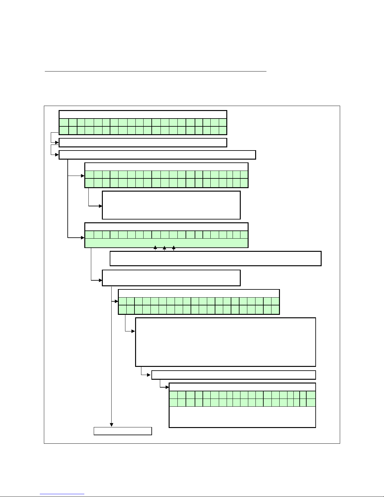
E93.0901EN.A Manual Consul+
61
10.13 Setting the maintenance specifications
MAINTENANCE SETTINGS
The unit can be programmed in such a way that an automatic maintenance message is displayed.
There are three options that can be selected. A maintenance message appears after:
* A programmed date is reached.
* An amount of burning hours is reached.
* An amount of ignition cycles is reached.
A single option can be activated or all three options.
Operating screen:
W A T R H T R : b o i l e r o f f
> > > : 1 2 3 . 4 ° C ( 1 2 3 . 4 ° C
)
Press [MENU]
Select "Maintenan" using [◄] & [►] and press [ENTER]
Operating screen:
M a i n t e n R e s e t
Press [▲] to reset the:
Counter for the total amount of burning hours.
Counter for the total amount of ignition cycles.
(The text will blink once briefly after resetting).
Operating screen:
M a i n t e n M o d e
Blinking second line.
What is blinking at the second line (before a selection is made) is the active maintenance option.
Press [▲] or [▼] to change the selected
blinking option.
Screen: Selecting of all maintenance options.
M a i n t e n M o d e
A l l
Press [►] to set:
The option that is blinking can be changed using by [▲] & [▼]
* Date for the Maintenance message.
* Total amount of burning hours for the Maintenance message.
* Total amount of ignition cycles for the Maintenance message.
After selecting one of these values the water heat er returns to the
maintenance operating screen.
Press [ENTER] to confirm the changes.
Confirmation screen:
A r e y o u s u r e
< C a n c e l ; > C o n f i r m
Press [◄] to cancel the changes or [►] to confirm the
changes. Hereafter the water heater returns to the op-
erating screen.
Go to next page
Page 62
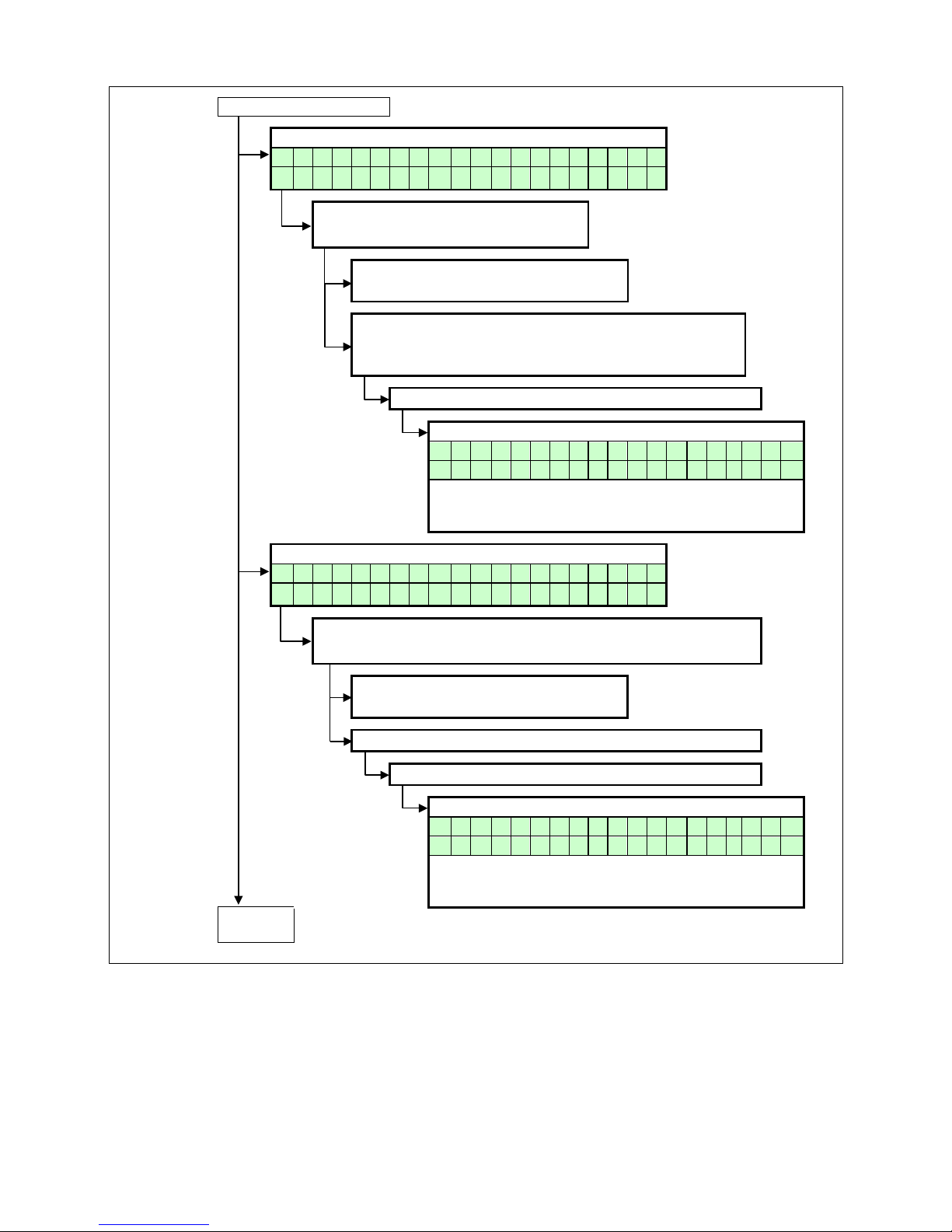
E93.0901EN.A Manual Consul+
62
From previous page
Screen: Selecting message at certain date.
M a i n t e n M o d e
D a t e
Press [►] to set:
The date for the maintenance message.
Press [◄] to:
Return to maintenance mode selection.
Press [►] to browse through the values that can be set
at the bottom line.
The blinking value can be changed with [▲] & [▼]
Press [ENTER] to confirm the changes.
Confirmation screen:
A r e y o u s u r e < C a n c e l ; > C o n f i r
m
Press [◄] to cancel the changes or [►] to confirm the
changes. Hereafter the water heater returns to the oper-
ating screen.
Screen: Message after total amount of ignition cycles.
M a i n t e n M o d e
I g n i t i o n c y c l e s
Press [►] to set:
The total amount of ignition cycles for the Maintenance message.
Press [◄] to:
Return to maintenance mode selection.
The blinking value can be changed with [▲] & [▼]
Press [ENTER] to confirm the changes.
Confirmation screen:
A r e y o u s u r e < C a n c e l ; > C o n f i r
m
Press [◄] to cancel the changes or [►] to confirm the
changes. Hereafter the water heater returns to the oper-
ating screen.
Go to
next page
Page 63
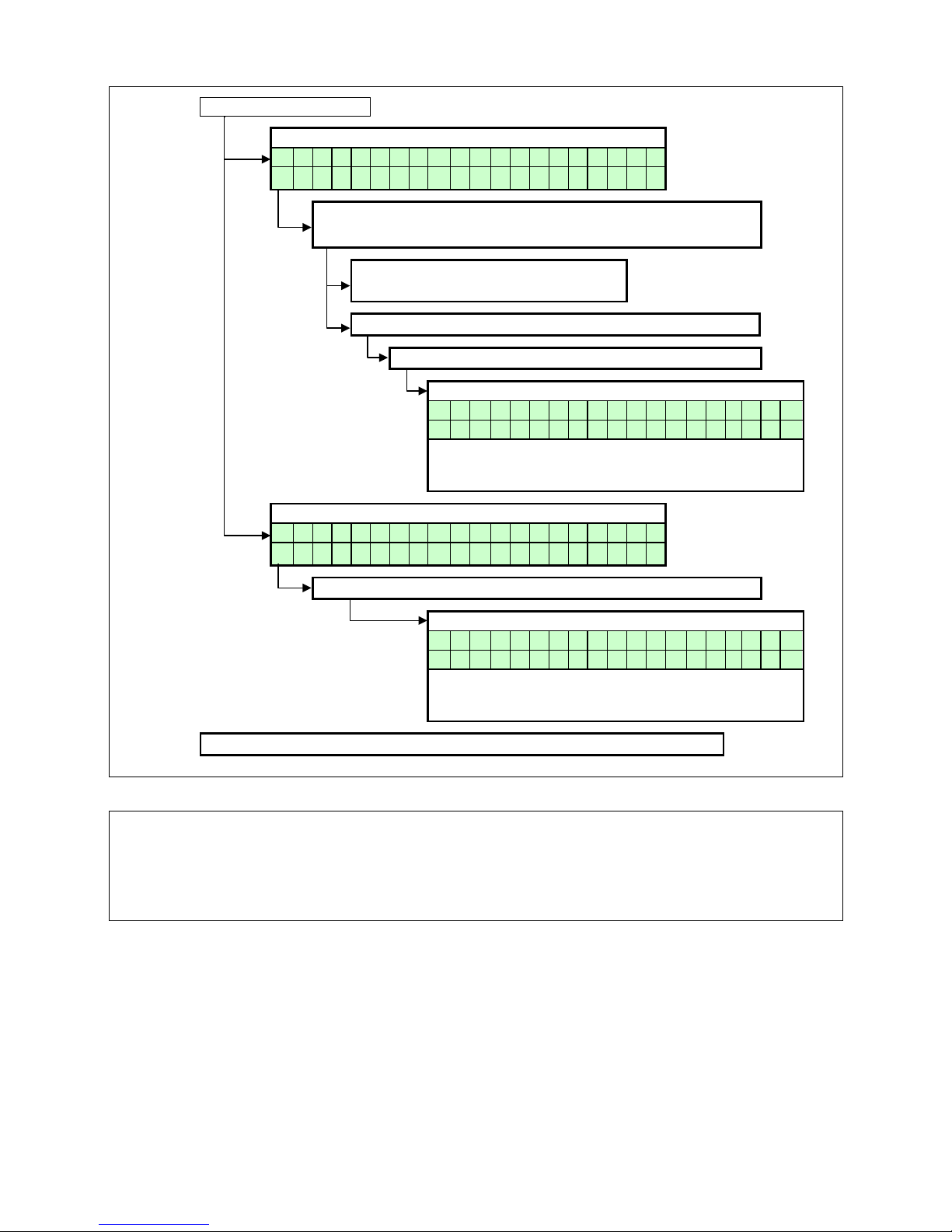
E93.0901EN.A Manual Consul+
63
From previous page
Screen: Message after total amount of burning hours.
M a i n t e n M o d e
B u r n i n g h o u r s
Press [►] to set:
The total amount of burning hours for the maintenance message.
Press [◄] to:
Return to maintenance mode selection.
The blinking value can be changed with [▲] & [▼]
Press [ENTER] to confirm the changes.
Confirmation screen:
A r e y o u s u r e
< C a n c e l ; > C o n f i r m
Press [◄] to cancel the changes or [►] to confirm the
changes. Hereafter the water heater returns to the oper-
ating screen.
Screen: No maintenance message will be displayed.
M a i n t e n M o d e
M a i n t e n O f f
Press [ENTER] to confirm the changes.
Confirmation screen:
A r e y o u s u r e < C a n c e l ; > C o n f i r
m
Press [◄] to cancel the changes or [►] to confirm the
changes. Hereafter the water heater returns to the oper-
ating screen.
Note: The [MENU] button will return the display to the oper ating screen.
BE AWARE: This f unction is standar d turned OFF . We off er this program mable functio n to the inst aller to u se
as a reminder. Bec ause it c onc erns a f r ee pr o gram mable function the use of it cannot be us e d as an argument
in warranty cases.
Our units must be maintained every twelve months whatever the settings/working of this function.
It is and remains the responsibly of the end user to have the unit maintained every twelve months.
Page 64
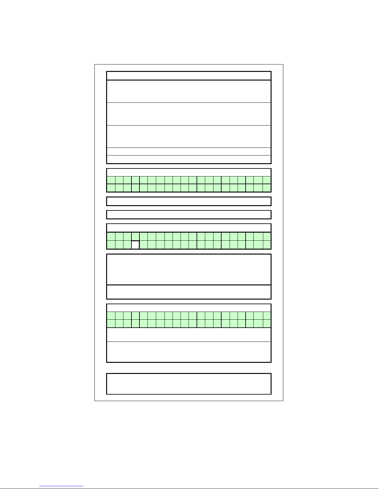
E93.0901EN.A Manual Consul+
64
10.14 Setting the user lock
The following graphs describe how to acti vate the user lock of the display. The s tandard factory sett ing for this
function is “OFF”.
The "USER LOCK" menu.
In this menu the water heater can be locked for (end-) users.
0 = UNLOCKED
1 = LOCKED
When the water heater is unlocked, the user can enter the
MENU by pressing the menu button and all screens
will show up.
When the water heater is locked, the user has to push the:
[MENU] button together with the [▼] button for 5 s.
to access all menu screens.
This function is to prevent accidental changes!
NOTICE: The PARAMETER screen always accessible.
Operating screen:
H E A T I N G
:
b o i l e r o f
f
> > > : 1 2 3 . 4 ° C ( 1 2 3 . 4 ° C
) Press [MENU]
Select "User lock" using [◄] & [►] and press [ENTER]
User lock screen:
S e t U s e r l o c k = 0
0
The "0" is now blinking/selected and can be changed.
Use [▲] & [▼] to change the value.
0 = User lock function OFF
1 = User lock function ON
Press [ENTER] for the confirmation screen after the selection
has been made.
Confirmation screen:
A r e y o u s u r e
< C a n c e l ; > C o n f i r m
Press [◄] to cancel the changes (the unit will reset and the
display returns to the operating screen).
Press [►] to confirm the changes. The changed value will be
blinking for a few seconds. After this, the display returns to the
operating screen.
NOTICE:
Using the [MENU] button during the User lock display, will re-
set the water heater and the water heater will return to the op-
erating screen. Changes will be neglected in this case.
Page 65
E93.0901EN.A Manual Consul+
65
10.15 Setting the parameters at the control panel
The functions of the control ler are em bedded in de electronics by means of par ameter s. The values and s etting s
hereof can be progr ammed by a skilled an d trained service engineer with the help of a computer (laptop), the
correct software and an interface cable. A selection of these parameters can be programmed at the control panel
of the unit itself, without the use of a computer.
The following table gives a list of these last mentioned parameters. NOTICE: Only the password for level 1 is
issued in this manual. “More advanced” parameters need to be programmed by a skilled and trained service engineer with access to level 2.
When ‘Modify = no’, the parameter can only be programmed at level 2
PASSWORD:
1342
MENU
PARA-
METER
DESCRIPTION UNITS TEXT DISPLAY
LEVEL 1
Modify
HEATING
A
1
P5BE
Step modulation (1=on 0=off)
-
S t e p m o d u
l
no
2
P5AO
Blocking offset flow temperature control
°C
H E s O f f 1
3
yes
3
P5AP
Proportional range temperature control
°C
H E s P r b 1
3
no
4
P5AL
Hysteresis CH Flow temperature control
°C
H E s c D i f 1
3
yes
5
P2IC
Integration time temperature control
s
H E s I n t 1
3
no
6
P2MI
Blocking offset System CH temperature control
°C
H E c O f f
3
yes
7
P2MJ
Proportional range System CH temp. control
°C
H E c P r b
3
no
8
P2MK
Integration time CH temperature control
s
H E c I n t
3
no
9
P5AB
Timer Contact (1=on)
-
T i m e r C o n t
yes
DHW
B
1
P4AB
DHW Pump Config 0=Pump 1=TWV
-
D H i p m p / t w
v
yes
2
P5CB
Flow temperature DHW tank low
°C
D H i f l o w L
O
yes
3
P5CK
Flow temperature DHW tank hi
°C
D H i f l o w H
I
yes
4
P5CL
Low Flow temperature time DHW
min
D H i L O t i m
e
yes
5
P5CD
Legionella temperature
°C
L e g i o t e m
p
no
6
P5CI
Legionella hyst DHW tank temperature
°C
L e g i o h y s
t
no
7
P5CJ
Legionella hold time (0=off)
min
L e g i o h o l
d
no
8
P2KI
CH interrupt by Legionella (0=yes)(1=no)
-
L e g i o i n t
r
no
9
P2LC
Regulation temperature offset DHWd
°C
D H d s c O f f 2
yes
A
P2MN
Proportional range DHWd modulation
°C
D H d s c P r b 2
3
no
B
P2LD
Regulation temperature hysteresis DHWd
°C
D H d s c D i f 2
yes
C
P2MO
integration time DHWd modulation
s
D H d s c I n t 2
3
no
D
P2ML
Sys temp blocking offset DHW tank
°C
D H d s c O f f 3
yes
E
P2MM
Sys temp b locking hysteresis DHW tank
°C
D H d s c D i f 3
yes
F
P5CA
Hysteresis DHW tank temperature
°C
D H i s c D i f 4
yes
G
P2KH
Gradient heat demand detect DHW tank temp.
°C
D H i d e t g r a
d
yes
CASCADE
C
1
P2MA
Max number extra heaters
-
M a x C a s c U n
t
no
2
P5DA
Bus address heater
-
B u s a d r e s
s
no
3
P5DC
Dhw on entire cascade(0) only master(1)
-
D H i c a s / m a
s
no
4
P5DE
Extra Heater output enable(1)
-
E x t r a u n i
t
yes
5
P5DF
Cascade detection (0=standalone 1=Leader)
-
C a s S i / M a
no
6
P5BL
Power off total cascade (1)
-
P w r O f f T o C
a
no
7
P5DB
Number of heaters with common flue 0=None
-
C o m F l u N u m
no
GENERAL
D
1
P5BB
Analogue input Config (0=off 1=temp)
-
A n I n p C o
n
yes
2
P5AI
Minimum Temperature 0-10V input
°C
0 - 1 0 M i n T m
p
yes
3
P5BI
Altitude (in amounts of 100 ft.)
ft*100
A l t * 1 0 0 f
t
yes
4
P2LK
Max cooling time
min
M a x C o o l T i
m
yes
5
P5BJ
Temperature display 1=on
-
T e m p O n D i s
p
yes
6
P4AA
DHW 0=off 1=Indirect 2=Direct
-
D H W 1 = i 2 =
d
no
7
P4AD
pressure 0=off 1=sensor and 2=switch
-
c o n f i g
no
8
P4BD
Gas type values 0-2
-
g a s t y p e
no
9
P4BE
Soft start type values 0-2
-
c o n f i g
no
A
P5BN
Pump modes 0-3
-
c o n f i g
no
For extensive explanation see Ch. 11: ‘Controlling options and settings’, page 70 ff.
IMPORTANT: Do not change the parameters P4AA, P4AD and P5BI; they are present in the controller for different
purposes than DHW control.
Changing these par ameters may affect water heater operation negatively and can
cause unsafe situations.
Parameter screens + concise explanation see next pages →
Page 66
E93.0901EN.A Manual Consul+
66
Operating screen:
W A T R H T R : b o i l e r o f f
> > > : 1 2 3 . 4 ° C ( 1 2 3 . 4 ° C
)
Press [MENU]
Select "Parameter" using [◄] & [►] and press [ENTER]
Parameter menu:
I n s t a l l e r c o d e
0 0 0 0
Enter the 4-digit code with the [◄] & [►] and the
[▲] & [▼] buttons and select [ENTER]
The code will blink a few seconds and when entered
correctly, the following parameters will be displayed.
NOTICE: These codes are user based and give access
to a selected number of parameters, which
can be changed (Installer level 1/2).
Menu A: Heating
A 1 S t e p m o d u l 1
Function to activate the step modulation:
0 = Off
1 = On
Menu A: Heating
A 2 H E s o f f 1 3 4 ° C
CH supply temperature setting. This parameter
is the offset of the programmed CH temperature.
Menu A: Heati ng
A 3 H E s P r b 1 3
2 5 ° C
Select the CH supply temperature control. This parameter
is the proportional range of the selected CH supply temperature.
Menu A: Heating
A 4 H E s c D i f 1 3
1 0 ° C
Select the CH supply temperature control. This parameter
is the hysteresis of the selected CH supply temperature.
Menu A: Heating
A 5 H E s l n t 1 3
6 0 S e c
Select the CH supply temperature control. This parameter
is the integration time of the selected CH supply temperature.
The screen texts on these
pages are standard part of
the software and apply to
CH systems (boilers)
and/or DHW devices (water
heaters).
Page 67
E93.0901EN.A Manual Consul+
67
Menu A: Heating
A 6 H E c O f f 3
4 ° C
Select the cascaded heaters supply temperature control.
This parameter is the offset of the selected CH supply tem-
perature of EACH water heater of the total cascade.
Menu A: Heating
A 7 H E c P r b 3 2 5 ° C
Select the cascaded water heaters supply temp. control.
This parameter is the proportional range of the selected CH
supply temperature of EACH water heater of the total cas-
cade and of the external (cascade) sensor.
Menu A: Heating
A 8 H E c l n t 3 8 0 S e c
Select the cascaded water heaters supply temp. control.
This parameter is the integration time of the selected CH supply temperature of EACH water heater of the total cascade
and of the external (cascade) sensor.
Menu A: Heating
A 9 T i m e r C o n t 0
Function to activate "external time controller":
0 = Off
1 = On
Connect to 13-14. Contact closed = daytime setting,
Contact open = night-time setting.
Menu B: Hot water
B 1 D H i p m p / t w v 1
Hot water function of the water heater by:
0 = pump
1 = 3-way valve
Menu B: Hot water
B 2 D H i f l o w L O 2 5 ° C
Hot water function of the water heater. This parameter is the
CH supply temperature LOW level with an indirect hot water
demand.
Menu B: Hot water
B 3 D H i f l o w H I
8 5 ° C
Hot water function of the water heater. This parameter is the
CH supply temperature HIGH level with an indirect hot water
demand.
The screen texts on these
pages are standard part of
the software and apply to
CH systems (boilers)
and/or DHW devices (water
heaters).
Page 68
E93.0901EN.A Manual Consul+
68
Menu B: Hot water
B 4 D H i L O t i m e 1 M i n
Hot water function of the water heater. This parameter is the
selectable period after which the water heater switches from
LOW to HIGH set point with an indirect hot water demand.
Menu B: Hot water
B 5 L e g i o t e m p
8 5 ° C
Pasteurization function of the water heater. This parameter is
the selected hot water temperature during the pasteurization
function of the water heater.
Menu B: Hot water
B 6 L e g i o h y s t 2 ° C
Pasteurization function of the water heater. This parameter is
the selected hysteresis during the pasteurization function of
the water heater.
Menu B: Hot water
B 7 L e g i o h o l d 2 M i n
Pasteurization function of the water heater. This parameter is
the selected time period for the pasteurization function of the
water heater.
Menu B: Hot water
B 8 L e g i o i n t r
0
Pasteurization function of the water heater. This parameter
controls if the CH demand can be interrupted by the pasteurization function of the water heater.
0 = Yes
1 = No
Menu B: Hot water
B 9 D H d s c O f f 2 4 ° C
Function for the direct hot water heater.
This parameter is de off set of the selected HW temperature
of the water heater.
Menu B: Hot water
B A D H d s c P r b 2 3
2 0 ° C
Function for the direct hot water heater.
This parameter is the proportional range of the selected HW
temperature of the water heater.
Menu B: Hot water
B B D H d s c D i f 2 1 0 ° C
Function for the direct hot water heater.
This parameter is the hysteresis of the selected HW tempera-
ture of the water heater.
The screen texts on these
pages are standard part of
the software and apply to
CH systems (boilers)
and/or DHW devices (water
heaters).
Page 69
E93.0901EN.A Manual Consul+
69
Menu B: Hot water
B C D H d s c l n t 2 3
2 0 0 S e c
Function for the direct hot water heater.
This parameter is the integration time of the selected HW
temperature of the water heater.
Menu B: Hot water
B D D H d s c O f f 3 4 ° C
Function for the cascaded direct hot water heaters.
This parameter is the offset of the selected HW temperature
of the cascaded water heaters.
Menu B: Hot water
B E D H d s c D i f 3 8 ° C
Function for the cascaded direct hot water heaters.
This parameter is the hysteresis of the selected HW temper-
ature of the cascaded water heaters.
Menu B: Hot water
B F D H i s c D i f 4 5 ° C
Function for the indirect hot water supply of the
water heater (tank).
This parameter is the hysteresis of the selected DHW tem-
perature of the calorifier/tank.
Menu B: Hot water
B G D H i d e t g r a d
3 ° C
Function for the indirect hot water supply of the
water heater (tank).
This parameter detects an (an accelerated) hot water de-
mand, when a larger (water) amount is being used.
Menu C: Cascade
C 1 M a x C a s c U n t 1 1
Function for the cascading of the water heater(s).
This parameter sets the total number of cascaded water
heaters (max. twelve water heater s).
Menu C: Cascade
C 2 B u s a d r e s s 0
Function for the cascading of the water heater(s).
This parameter determines the address of the water heater
for the total cascading control.
Master = 0, Slave 1 = 1 etc.
Menu C: Cascade
C 3 D H i c a s / m a s 0
Function for the cascading of the water heater(s).
This parameter determines if only the Master water heater or
all water heaters of the cascade are used for indirect hot water.
0 = All
1 = Master
The screen texts on these
pages are standard part of
the software and apply to
CH systems (boilers)
and/or DHW devices (water
heaters).
Page 70
E93.0901EN.A Manual Consul+
70
Menu C: Cascade
C 4 E x t r a u n i t 0
Function for the cascading of the water heater(s).
This parameter is activated when an external (extra) water
heater is connected to the Master water heater. Connect to
the Master connections 21-22.
Menu C: Cascade
C 5 C a s S i / M a 0
Function for the cascading of the water heater(s).
This parameter sets the function of the water heater at a cascade alignment
0 = Slave unit
1 = Single / Master un it
Menu C: Cascade
C 6 P w r O f f T o C a 0
Function for the cascading of the water heater(s).
This parameter determines the function of the Slave water
heaters when the Master water heater is switched off.
0 = Slave water heater(s) continue operation
1 = Slave water heater(s) switch off
Menu C: Cascade
C 7 C o m F l u N u m 0
Function for the cascading of the water heater(s).
This parameter determines the number of cascaded water
heaters that are implemented with a common flue system.
Menu D: General
D 1 0 - 1 0 V c o n t r 0
Function for the external control of the water heater by using
a 0-10 Volt signal (Connections 15-16).
0 = No external control
1 = Control based on temperature setting
2 = Control based on power setting (NOT possible for Con-
sul+)
Menu D: General
D 2 0 - 1 0 M i n T m p 2 0 ° C
Function for the external control of the water heater by using a
0-10 Volt signal (Connections 15-16).
Control based on temperature (setting 1).
The minimum (desired) CH water temperature when
supplying a 1,4 Volt signal.
Menu D: General
D 3 A l t * 1 0 0 f 0
Function for setting th e loc atio n height (abo ve se a level) of the
water heater.
NOTICE: dimensions in English feet. One unit = 100 ft.
Use this function only in consultation with the supplier/manufac-
turer.
The screen texts on these
pages are standard part of
the software and apply to
CH systems (boilers)
and/or DHW devices (water
heaters).
Page 71
E93.0901EN.A Manual Consul+
71
Menu D: General
D 4 M a x C o o l T i m 2 M i n
Function for setting the maximum overrun time of the fan (max-
imum 10 minutes).
0 = Switch off
Menu D: General
D 5 T e m p O n D i s p 1
Function to show the (measured) temperature of the water
heater at the display.
Menu D: General
D 6 D H W 1 = i 2 = d 1
Function to set up the CH and HW boiler options.
0 = CH only (direct)
1 = CH/HW function (indirect)
2 = HW only (direct)
For Consul+ this parameter has been set 2.
Menu D: General
D 7
c o n f i g
Function for the setting of the water pressure.
Up to 4 bar a sensor is used, up to 6 bar a switch.
0 = off
1 = sensor
2 = switch
Menu D: General
D 8
g a s t y p e
Function to select the gas type (according to EN 437)
0 = standard
1 = G31
2 = Do NOT use.
Menu D: General
D 9
c o n f i g
Function for setting the 'soft start' option
0 = normal start-up
1 = reduced fan ramp-up speed (I)
2 = reduced fan ramp-up speed (II)
Menu D: General
D A
c o n f i g
Function: Pump mode
0 = normal
1 = relay 1, connector 19 and 20 (lock-out)
2 = relay 2, connector 21 and 22 (burner burning)
3 = relay 3, connector 23 and 24 (heat demand)
4 = Do not use (reserved for future applications).
The screen texts on these
pages are standard part of
the software and apply to
CH systems (boilers)
and/or DHW devices (water
heaters).
Page 72
E93.0901EN.A Manual Consul+
72
10.16 Fault codes display
The following graphs descr ibe th e lock out c odes of th e wat er heater . A lock out c ode ca n onl y be rem oved by a
manual reset of the water heater. NOTICE: Before resetting the water heater always check the water heater, DHW
system and all components c orresponding to the relat ed lock out description. Never just reset the water heater,
before analyzing the possible cause of failure.
10.16.1
LOCK-OUT CODES
Having a lockout means that the water heater needs a manual reset to start operating again.
When the water heater is in lockout the backlight of the display is blinking on and off.
Explanation >
9 9 9 , 5 : h r s
= time elapsed after fault & message.
Explanation >
P u m p 1 o
n
= status of the pump during fault.
Display message
F10
F a l s e f l a m e s i g n a l
p u m p o n
9 9 9 , 5 h r s
Reason
Flame signal is detected while it cannot be expected.
Display message
F8
F a i l e d b u r n e r s t a r t
p u m p o n 9 9 9 , 5 h r
s
Reason
Water heater is not starting after the programmed starting attempts.
Display message
F11
F a n s p e e d i n c o r r e c t
p u m p o n
9 9 9 , 5 h r s
Reason
The controller does not detect a correct fan speed.
Display message
F9
F l a m e l o s t
p u m p o n 9 9 9 , 5 h r
s
Reason
Flame detected during normal operation, but was lost while running.
Display message
F1
F l o w h i g h T e m p
p u m p o n 9 9 9 , 5 h r
s
Reason
Flow temperature exceeds the limit which has been set in the parameters.
Display message
F16
F l o w R e t u r n d t f a u l t
p u m p o n 9 9 9 , 5 h r
s
Reason
Temperature difference between flow and return exceeds limitation value,
or 'dT block or delta direct block' has occurred three times.
Display message
F0
F l o w s e n s o r e r r o r
p u m p o n 9 9 9 , 5 h r
s
Reason
Flow sensor not detected by the water heater caused by faulty connection/sensor.
Display message
F6
F l u e s e n s o r e r r o r
p u m p o n 9 9 9 , 5 h r s Reason
Flue gas sensor not detected caused by faulty connection/sensor.
Display message
F7
F l u e t e m p t o o h i g h
p u m p o n 9 9 9 , 5 h r s Reason
Flue gas temperature exceeds the limit more than 3 times within a time frame.
Display message
F13
P a r a m / H a r d w f a u l t
p u m p o n
9 9 9 , 5 h r s
Reason
Fault during programming of the water heater software parameters.
Page 73
E93.0901EN.A Manual Consul+
73
Display message
F1
R e t u r n h i g h T e m p
p u m p o n 9 9 9 , 5 h r
s
Reason
The maximum return temperature as set in the parameters is exceeded.
Display message
F3
R e t u r n s e n s o r e r r o r
p u m p o n 9 9 9 , 5 h r
s
Reason
Return sensor not detected caused by faulty connection/sensor.
Display message
F17
W a t e r h i g h l i m i t
p u m p o n
9 9 9 , 5 h r s
Reason
Maximum thermostat (clixon) measured a too high flow temperature.
10.16.2
BLOCKING CODES
The following graphs desc r ibe the blocking codes of the water he ater. A bloc king code is a temporary blocking of
the water heater, because of an extraordinary situation. The water heater will continue to operate after stabilisation
of this situation.
The display is not blinking, but is lightened up during the blocking period.
The water heater is b locking an action b ecause of an ex traordinary situat ion. This action will be continue d after
elimination of the extraordinary situation.
Display message
C a s c a d e B l o c k
9 9 9 , 5 h r
s
Reason
One of the cascaded water heaters causes an error, because of a lock out.
Display message
D e l t a D i r e c t b l o c k
9 9 9 , 5 h r
s
Reason
Temperature difference T2-T1 has exceeded the blocking value.
Display message
F12
p r o g r a m m i n g e n d
p u m p o n
9 9 9 , 5 h r s
Reason
Software parameters have been programmed.
Display message
F19
S i p h o n s w i t c h
p u m p o n
9 9 9 , 5 h r s
Reason
The pressure switch detects a high pressure in the flue/siphon system.
Display message
A n t i c y c l e t i m e
9 9 9 , 5 h r
s
Reason
The controller received a new heat demand too quick after the last demand.
Display message
D e a i r a t i o n
9 9 9 , 5 h r
s
Reason
The heater starts its deairation function and will return to normal operation.
Display message
F l o w h i g h D H W
9 9 9 , 5 h r
s
Reason
Setp.return (tank) temp. DHW (S3) is higher than Setp. heating = flow temp.
Page 74
E93.0901EN.A Manual Consul+
74
Display message
F l o w t e m p h i g h
9 9 9 , 5 h r
s
Reason
The flow temperature has exceeded the blocking temperature.
Display message
F l u e t e m p h i g h
9 9 9 , 5 h r
s
Reason
Flue gas temperature has exceeded the limit.
Display message
G e n B l o c k
9 9 9 , 5 h r s
Reason
The general blocking circuit is activated during operation = contact 7-8
Display message
L i n e f a u l t
9 9 9 , 5 h r s
Reason
Display message
R e t u r n t e m p h i g h
9 9 9 , 5 h r
s
Reason
temperature has not exceeded the lock-out value.
Display message
T 2 - T 1 h i g h
9 9 9 , 5 h r
s
Reason
Temperature difference T2-T1 has exceeded the blocking value.
Display message
W a t e r p r e s s u r e f a u l t
9 9 9 , 5 h r
s
Reason
Water pressure is too low or too high.
Display message
W A T R H T R : T 3 E x t e r n a l
> > > : 6 0 . 0 ° C ( - 3 0 . 7 ° C
)
Reason
Page 75
E93.0901EN.A Manual Consul+
75
10.16.3 MESSAGES
The following graphs describe the messages at the water heater display. Depending on the selected and activated
options for the water heater, it is possible that some messages will show up at the display of the water heater. For
example, a mainte nance m essage af ter a c ertain pr ogram med date has been r eac hed. The wat er heater will operate independently of these messages.
MAINTENANCE ATTENTION MESSAGE
The display shows alternating the base screen and this message, while the backlight is blinking.
The water heater is operating, but will count the exceeding hours.
A parameter must be changed, after service, to remove this message.
Display message
N e e d s M a i n t e n a n 0 . 0 I g n i t i o n c y c l e s h r s Reason
Maintenance option of total amount of ignition cycles has been reached.
Display message
N e e d s M a i n t e n a n 0 .
0
D a t e h r s
Reason
Maintenance option of the date has been reached.
Display message
N e e d s M a i n t e n a n 0 .
0
B u r n i n g h o u r s h r s
Reason
Maintenance option of total amount of burning hours has been reached.
Display message
N e e d s M a i n t e n a n 0 .
0
A l l h r s
Reason
One of the abovementioned maintenance options has been reached.
Page 76
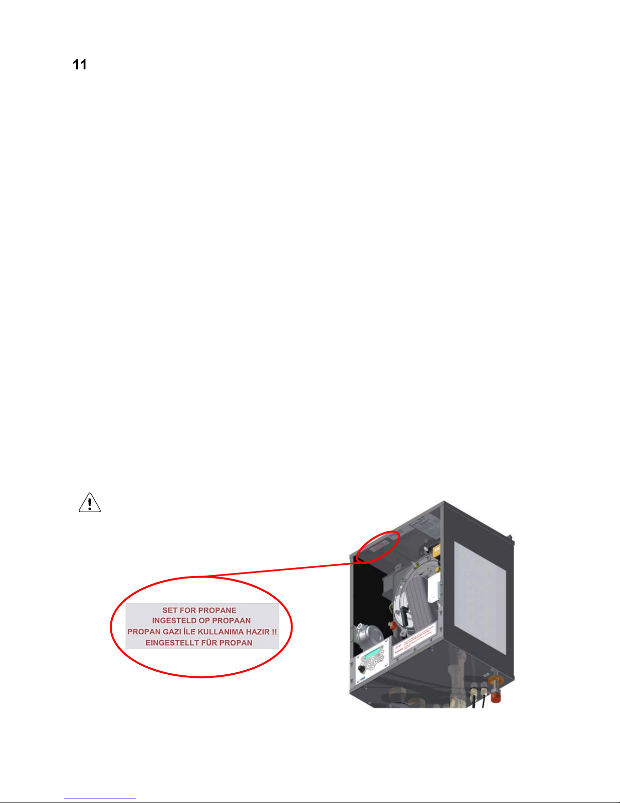
E93.0901EN.A Manual Consul+
76
CONTROLLING OPTIONS AND SETTINGS
11.1 General
The following sections describe some general functions of the water heater and their possible use.
11.1.1
MAX COOLING TIME
The fan will cool down the heat exchanger accordin g to the temperature sett ings (parameters) of the s oftware.
With this cooling parameter the maximum run time of the fan can be progr am med.
P2LK Max cooling time (display D4) [min.]
The fan will cool the heat ex changer according to par ameter P2 LJ, but the fan wil l never run for cooling lo nger
than the period programmed with this parameter P2LK. “0” = cooling function off.
For S1 > local set point P6BA – P2LJ → fan starts after 1 minute and stops after 3 minutes
During post pump circulation, no post ventilation takes place.
11.1.2
TEMPERATURE DISPLAY ON/OFF
Selection for showing the measured temperatures in the operation display of the water heater.
P5BJ Temperature display 1=on (display D5)
The measured temperature in the operation display.
0 = not visible
1 = visible
11.1.3
GAS TYPE SELECTION
Settings for gas types: natural gas or propane.
P4BD Gas type (display D8) 0=standard, 1=propane, 2=Do NOT use.
This parameter is set 0 for the common used gas types such as natural gas G20 or G25.3
By setting this parameter 1 for propane (G31) the fan speed is reduced.
0 = standard gas (e.g.: natural gas)
1 = propane
2 = Do NOT use
By each setting, the releva nt Soft start settin gs are autom atically adjusted, depending on its main setting P4 BE,
see next section § 11.1.4.
In case of gas conversion, paste the corresponding
sticker at the appropriate pos
ition in the water
heater and mark the square for the used gas type.
Page 77
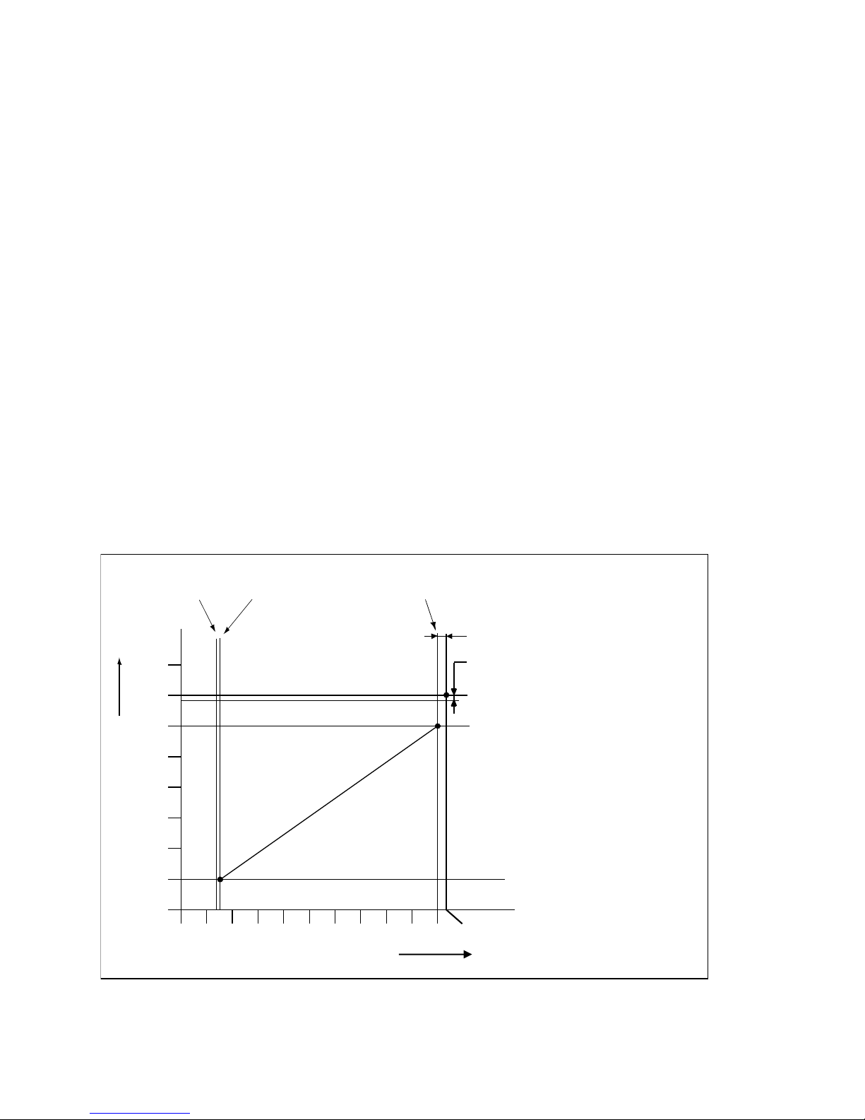
E93.0901EN.A Manual Consul+
77
11.1.4 SOFT START OP TION
Start parameters can be modified to achieve better start behavior, in case of noise or other difficulties. This is done
by reducing the fan ramp-up speed. Two reduced settings are available (I and II).
P4BE Soft start (0=normal, 1=reduced fan ramp-up speed (I), 2= reduced fan speed ramp-up (II))
(display D9).
0 = normal start-up
1 = reduced fan ramp-up speed (I)
2 = reduced fan ramp-up speed (II)
11.1.5
TANK SENSOR SENSITIVITY
P2KH Gradient heat demand detection DHW tank temperature (display BG) [0.1°C]
With S3 in use as tank s ensor, it is poss ible to detec t a fas t cooling dow n of the tank through a large DHW f l ow.
The sensitivity of this sensor can be set in parameter P2KH in tenths of degrees.
11.2 Water heater options
11.2.1 0-10 VDC REMOTE FLOW TEMPERATURE SET POINT
The hot water temperature is contr olled b y connecting an ex ternal 0-10 VDC signal to the water h eater (connec-
tions 15-16).
P5BB Analogue input Config (0=off 1=temp) (display D1).
This parameter must be set at "1" so the supplied 0-10 V dc signal will control the temperature set point.
Possible settings are:
0 = 0-10V control off
1 = 0-10V temperature set point control active
See also the following graph for the relation between the temperature and the control signal.
The graph is only for illustration purposes, parameter values in the water heater can deviate.
BE AWARE: Legionella cycle starts at 10.2 Volts.
0 1 2 3 4 5 6 7 8 9 10 10.2
0 – 10 VDC stuursignaal
80
70
60
50
40
30
20
10
0
P2GD offset legionella
P5CI hysterese legionella
P5CD legionella temp
P6CA max. temp.-instelling
P5CH min. temp.-instelling
P2GB uit P2GA aan P2GC max.
P5CD Legionella temperature
P2GD offset Legionella
P5CI hysteresis Legionella
P6CA max. temperature set point
e.g. 60°C
P2GB off P2GA on P2GC max.
Temperature setting °C
0-10 Vdc control signal
P5CH min. temp. set point
e.g. 20°C (default)
Page 78
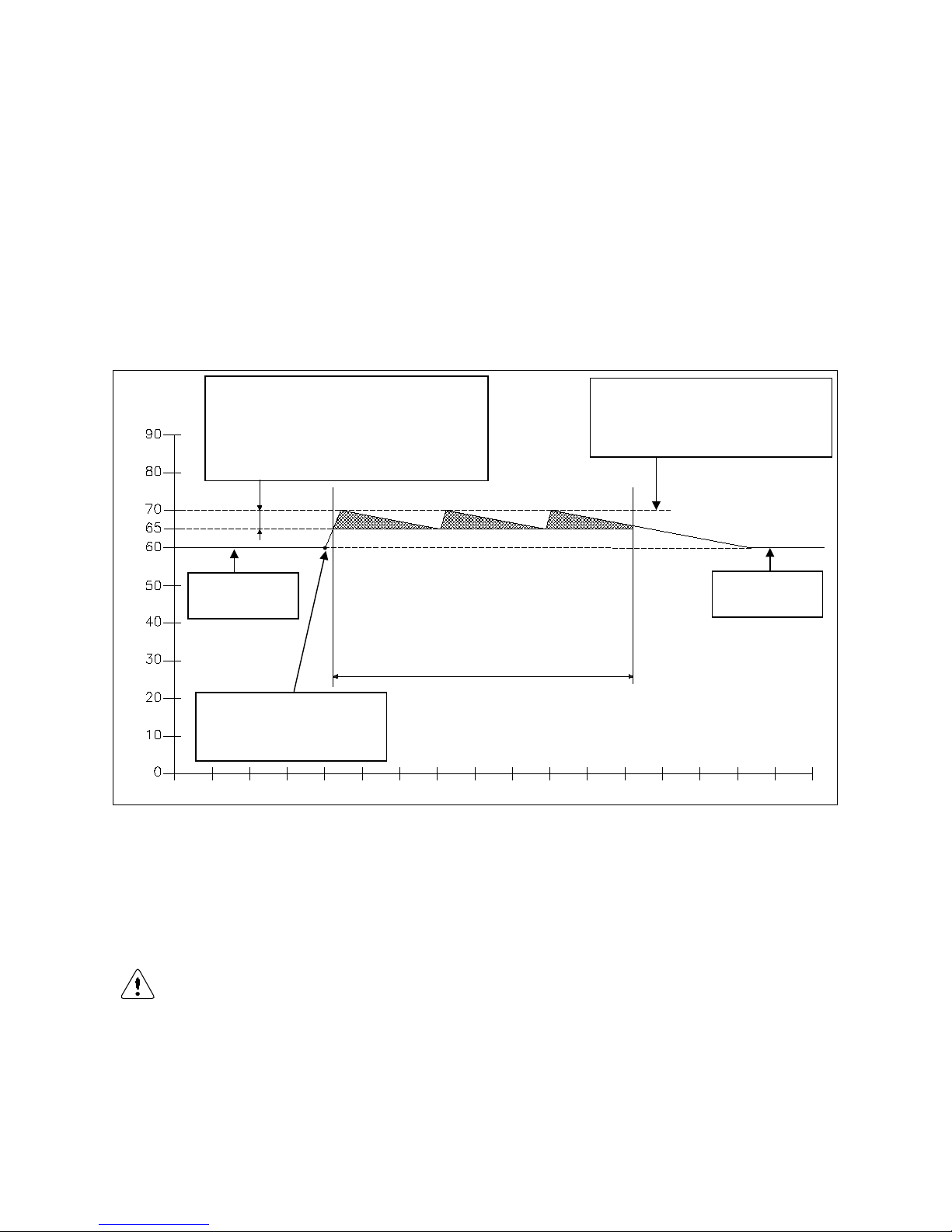
E93.0901EN.A Manual Consul+
78
11.2.2 ANTI-LEGIONNAIRES’ DISEASE (PASTEURIZATION) FUNCTION
To prevent Legionnaires ’ disease, the water heater (sof tware) provides a function f or heating up the hot water
storage tank (once a week or every day) to a higher water temperature than the normal active hot water set point.
Also, the period , that this “ higher ” water tem perature functio n mus t be active, c an be programm ed in P7 BV start
time (0:00) and P7BW (8) and is standard switched off.
Also, an external 0-10 Vdc signal can be used to activate the pasteurization function, by making the 0-10 V signal
higher than 10,2 V.
NOTICE: The standard factory setting for this Legionnaires’ disease (pasteurization) function is “OFF”. To activate
this Legionnaires’ diseas e function some parameters must be progr ammed by the manufacturer/supplier. T he
starting day and starting time of this Legionnaires’ disease function can be programmed at the control panel of the
water heater.
Several parameters are used for this function. Three of these parameters are shown in the following graph.
The graph is only for illustration purposes, parameter values in the water heater can deviate.
The settings of thes e parameters P5CI, P5CJ and P5CD m ust be programm ed according to all appl icable anti
Legionnaires’ disease preventing regulations.
The setting of these param eters can onl y be done b y the m anuf actur er/suppl ier of the water hea ter or by a tech-
nician with access to programming level 2, at the control panel of the unit without the use of a computer.
NOTICE: The use and act ivat ion of this function won’t guar a ntee a Le gi onn air es’ disease free instal lation. The responsibility for a Legionnaires' disease free installation remains at the end-user/owner.
P5CI = 5°C
This is the bandwith within which the Legionnaires'
temperature must stay duri ng the programmed dura-
tion time period. In this example the temperat ure is
allowed to fluctuate between 65°C and 70°C during
the anti Legionnaires' function.
P5CJ = 80 min.
This is the duration within which the water tempera-
ture must be between the 65°C and 70°C.
P5CD = 70 °C
This is the maximum temperature during anti
Legionnaires' disease function period.
Normal setting wa-
ter temperature.
Start of the anti Legionnaires' dis-
ease program (start day and time
can be programmed).
Normal setting wa-
ter temperature.
Time (10 min steps)
Water temperature (°C)
Page 79
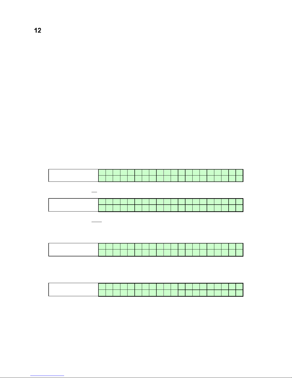
E93.0901EN.A Manual Consul+
79
COMMISSIONING THE WATER HEATER
12.1 First: flushing the water heater with water
After installation of the water heater the first step, before commissioning, is to flush the water heater and the whole
DHW installation with fresh water to remove pollution, debris and other materials that might cause a blocking. This
must also be done with installations, where only the water heater is replaced.
12.2 Second: filling & venting the water heater and the system
After flushing the water h eater and the installation t he s ystem can be filled with fresh water b y opening th e wat er
supply valve of the s ystem and opening al l the taps that are on th e system. T he water pressure of the s ystem
should be between a m inim um of 1 bar and a m ax imum of 8 bar, also dep endin g on t he ap plied pr essure s af et y
valve.
BE AWARE: The Consul+ water he ater has a manual air vent situated at the top panel of t he water h eater. This
vent must be opened durin g the fillin g of the wat er heater and the DHW system to m ake sure t hat no air/ox ygen
is trapped in the heat exchanger of the water heater.
NOTICE: Make sure that, during flushing and filling, no water can reach any electrical parts of the water heater.
12.3 Third: check the water flow
Before the water heater will be started, be sure that the pump is functioning and that there is a water flow through
the heat exchanger. Chec k t he electr ical po wer supp ly of the water h eater . When this is connected c orrec tl y, the
display will show:
Display message
B o i l e r o f f
Reason
Water heater is not active. T o activate the water heater press [ON/OFF] button
for six seconds.
Display message
W A T R H T R : b o i l e r o f f
> > > : 1 2 3 . 4 ° C ( 1 2 3 . 4 ° C
)
Reason
Water heater is standby. To activate the water heater press [ON/OFF] button
for three seconds.
Activate the water heater by pressing the ON/OFF button for six resp. three seconds. After this the following message will appear:
Display message
W A T R H T R : N o d e m a n d
> > > : 1 2 3 . 4 ° C ( 1 2 3 . 4 ° C
)
Reason
Water heater is active, but there is no heat demand.
When there is no water pre sent i n the water he ater or the water pr essur e is to o lo w, the water heater will go into
lock-out and will show a corresponding message in the display.
Display message
W a t e r p r e s s u r e f a u l t
9 9 9 , 5 h r
s
Reason
Water pressure is too low or too high.
Page 80
E93.0901EN.A Manual Consul+
80
By pressing the [SERVICE] button of the water heater, the water heater can be started without a heating demand.
The water heater will start to fire and also the pump will start to run. Firing of the water heater without a water flow
(but filled with water) will c aus e the so ca lled “ boili ng noises”. Check dur ing t his “ service func tion” op erati on also
the flow and return temperatures of the water heater by pressing the [◄] button once. The temperature difference
of the flow and return must be at least 13°C and maximum 25°C. This temperature difference indicates that there
is (enough) water flo w over the water heater; this wat er flow prevents the heat exc hanger of possible damage
caused by a thermal overload.
Flow monitoring
Another safety feature of the water heater , to make sure that there is en oug h wat e r flow over the water heater, is
the monitoring of the flow and return temperatures (T2 and T1). When the temperature difference (delta T) between
flow and return exceeds a c ertain (set) value ( load depend ent), t he follo wing warning m es sages will b e sho wn in
the display.
Display message
T 2 - T 1 h i g h 9 9 9 , 5 h r
s
Reason
Temperature difference T2-T1 has exceeded the blocking value, as set in the parameters.
Display message
D e l t a D i r e c t b l o c k
9 9 9 , 5 h r
s
Reason
The temperature difference between flow and return has exceeded the blocking
value
When this temperature d ifference excee ds the lock -out setting, the water heater will s witch off and the following
lock out code will be shown at the display.
Display message
F16
F l o w R e t u r n d T f a u l t p u m p o n 9 9 9 , 5 h r
s
Reason
Temperature difference between flow and return exceeds limitation value, or ‘dT
block or delta direct block has occurred 3 times.
When these messages appear and/or t he water heater will lock out, it m eans that there is not enough f low over
the water heater. In this case check the functioning of the pump.
The water heater has a built-in water pres s ure s witc h. I f water pr ess ur e of the system drops under a cer tain li mit,
the water heater wi ll go in a lock-out.
During and after the commissioning of the water heater, the operation of the water heater pump must be checked,
before leaving the installation room.
NOTICE: Always check the running of the pump before firing the water heat er .
Page 81
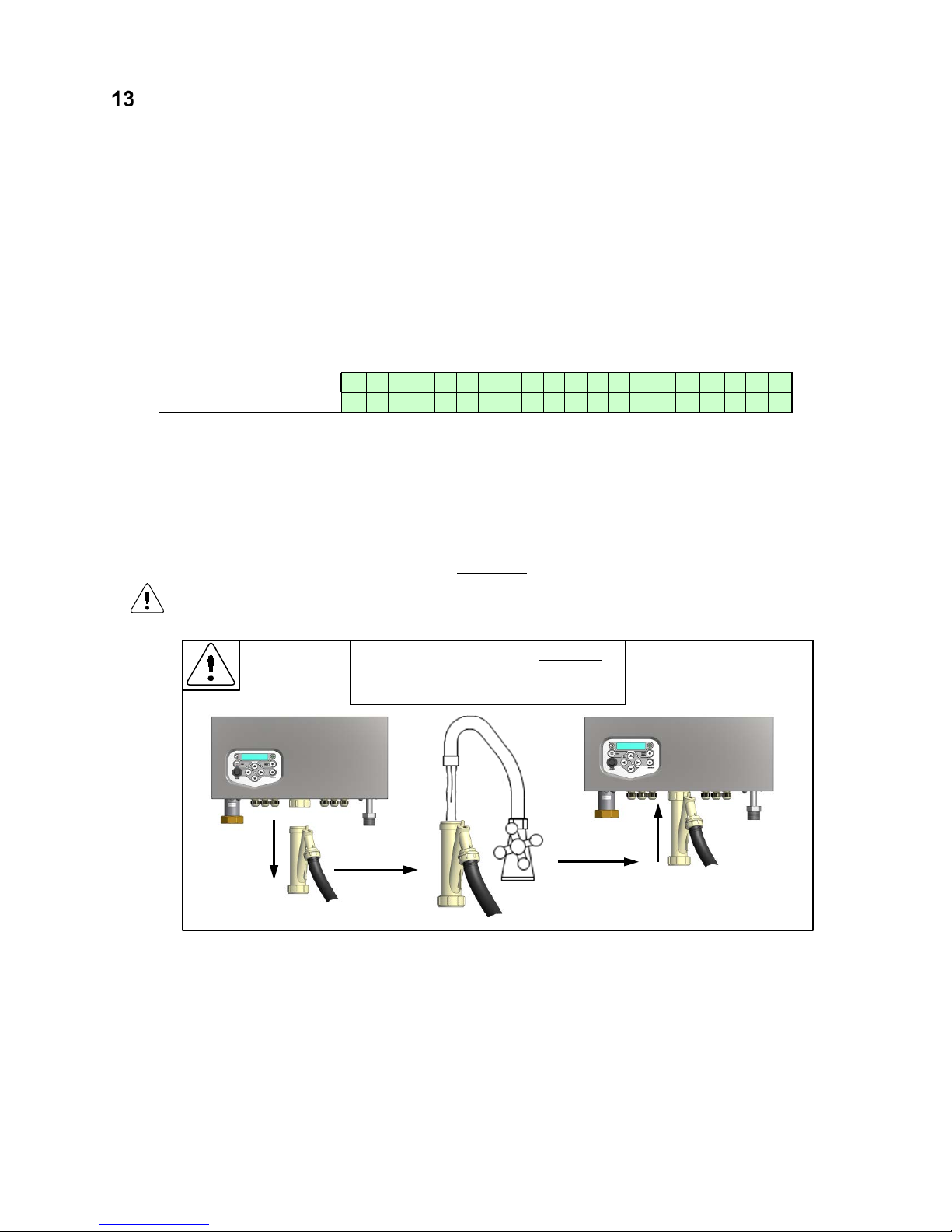
E93.0901EN.A Manual Consul+
81
STARTING THE WATER HEATER
13.1 General
Check the gas pressure av ailable at the gas conn ection pipe of the water heater . Use the pressure ni pple (3) of
the gas safety valve f or this m easurement. The gas p ressure f or the water heater, to operate prop erly under the
correct load, must be at least 20 mbar.
The picture at page 77 show the position of the pressure nipple (3) at the gas valve.
The Consul+ water heater has a manual air ve nt situa ted at the to p pane l of the water h eater . This vent m ust be
opened during the f il ling of the water heater . Make sure that, during flushing and f il ling, n o water can rea ch any
electrical parts of the water heater.
13.2 Firing for the first time
After the commissioning of the water heater and the described previous actions, the water heater display will show
the following graph.
Display message
W A T R H T R : N o d e m a
n
d > > > 1 2 3 . 4 ° C ( 1 2 3 . 4 ° C
)
Reason
Water heater is active, but there is no heat dem and.
The display describes:
• The actual operation
• If a heat demand is activated
• The temperature setting
• The temperature measured
When mounting the b ottom part of the siphon, befor e commissioning the water heater and/or after
maintenance, the siphon must ALWAYS be completely filled with water.
This is a s afety measure: the water in the siphon keeps the flue gases from leaking out of the
heat exchanger via the condensate drain.
When the water heater receives a heat demand the electronics will start the operation of the water heater. Before
the water heater is used, the burner must be adjusted and set at the minimum and maximum load.
The siphon must ALWAYS be completely
filled with water to the edge before placing
back on the unit
Page 82
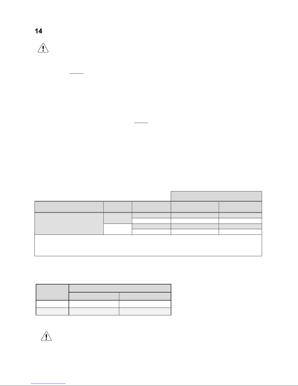
E93.0901EN.A Manual Consul+
82
ADJUSTING AND SETTING THE BURNER
Before carrying out any adjusting of the burner, carefully read this complete chapter.
14.1 Introduction
The burner must always be adjusted in the next situati ons :
A. - A new water heater is installed
- As part of a service/maintenance check, in case the CO
2
values turn out to be incorrect
Adjustment procedures for situation A are described in § 14.2.
B. - The gas control safety valve has been (re)placed
- Another type of gas is applied: gas conversion
Adjustment procedures for situation B are described in § 14.3.
In either of the four c ases des cribed in A and B, always check the gas /air r atio of the combustion figure (CO2) at
maximum and minimum input. First set the water heater at maximum load and subsequently at minimum load, and
repeat if necessary.
Set-up of this chapter:
First, all necessary values are g iven in the tables at § 14.1.1. A drawing of the gas valve(s) and s ett ing s cr ews is
given in § 14.1.3 on the next page. In § 14.1.4 a general scheme, conform which the adjustments must be carried
out, is presented. After that, in §§ 14.2 and 14.3 a thorough description is given of how to proceed in cases A and
B respectively. In § 14.4, finally, two main procedures used in the previous sections are described in detail.
14.1.1
GAS VALVE ADJUSTMENT: TABLES
Table 2
pre-adjustment settings gas valve for Consul+ water heaters
water heater
type
number of turns open (counter clockwise)
nat. gas G20 / G25.3 propane G31
Consul+ 35
0,5 0,25
Consul+ 55
1,0 0,5
The maximum fan speed must be reduced to convert the water heater into a propane (G31) appliance. Set parameter P4BD.
Table 1
gas type:
water heater type load output
nat.gas
G20 1/ G25.3 1
propane
G31
1, 3
Consul+ 35 2 & Consul+ 55 2
max. load
CO2 (%)
9,0 - 9,2
10,5 - 10,7
O2 (%)
4,5 - 4,8
4,6 - 4,9
min. load
CO2 (%)
8,5 - 8,7
9,3 - 9,5
O2 (%)
5,4 – 5,7
6,4 - 6,7
1
According EN437
2
All values are measured without front panel. The CO2 / O2 values should always be between the values
set at this table. Nominal values can be found at the Technical specifications datasheet page
3
Fan settings must be changed by altering parameter P4BD (display D8) (only by a skilled service engineer)
Page 83
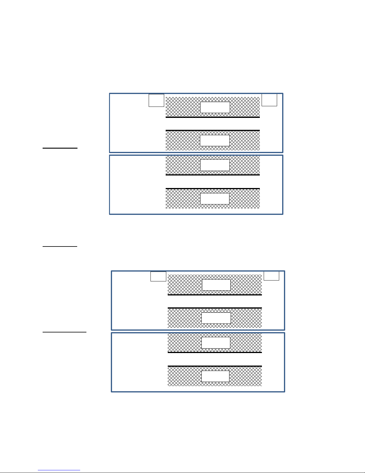
E93.0901EN.A Manual Consul+
83
14.1.2 ADJUSTMENT VALUES
To make adjustments easier, values of table 1 are presented in the following figures.
The CO
2
/ O2 values should always be between the values set in this figure.
Nominal values can be found in the Technical specifications table at the beginning of this manual.
All values are measured without front door.
G20, G25.3
___________________________________________________________________________________________
_
Propane G31
Fan settings must be changed by altering parameter P4BD (display D8). (only by a skilled mechanic).
The CO2 level may never be in the hatched area.
Propane: G31
adjust
adjust
adjust
adjust
max load
min load
4,5 %
4,8 %
5,4 %
5,7 %
O
2
9,2 %
9,0 %
8,7 %
8,5 %
CO
2
O.K.
O.K.
adjust
adjust
adjust
adjust
max load
min load
4,6 %
4,9 %
6,4 %
6,7 %
O2
10,7 %
10,5 %
9,5 %
9,3 %
CO2
O.K.
O.K.
Page 84
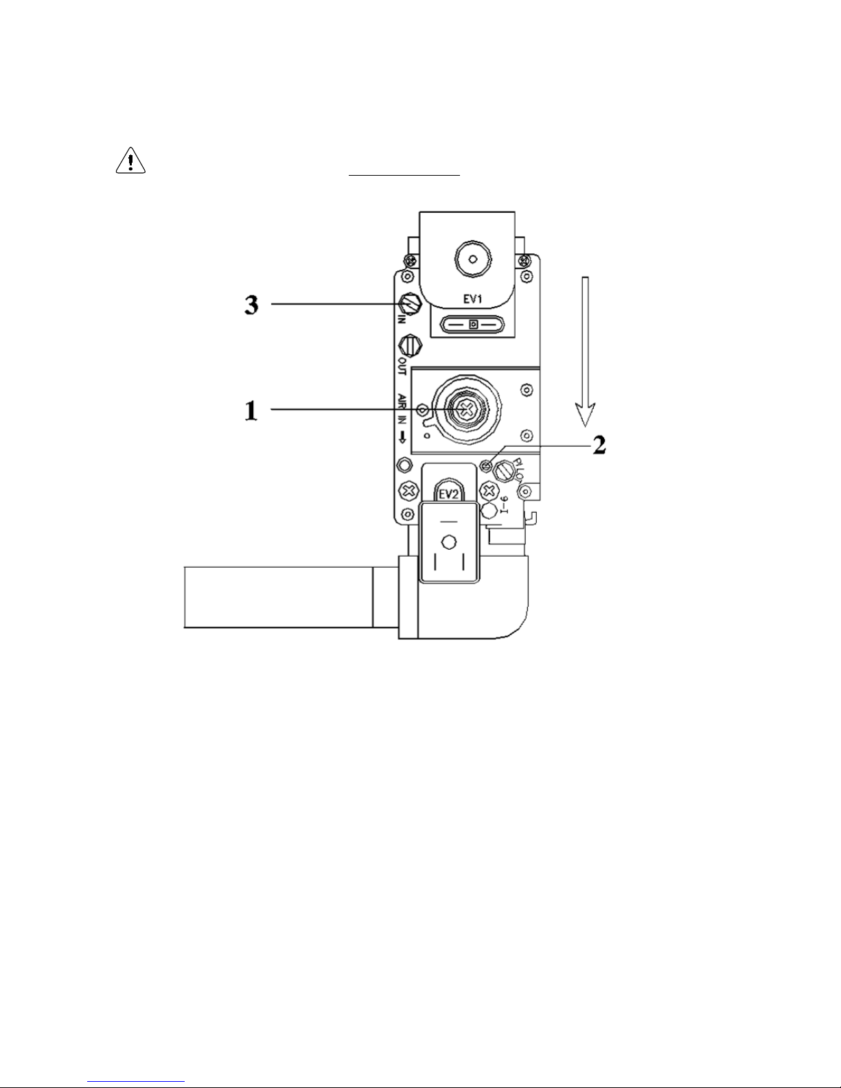
E93.0901EN.A Manual Consul+
84
14.1.3
SETTING SCREWS GAS VALVE(S): DRAWINGS
NOTICE: Do NOT mistake the screw marked ‘PILOT’ for screw 2.
→ Screw 2 is the SMALL screw immediately next to the pilot screw.
Page 85
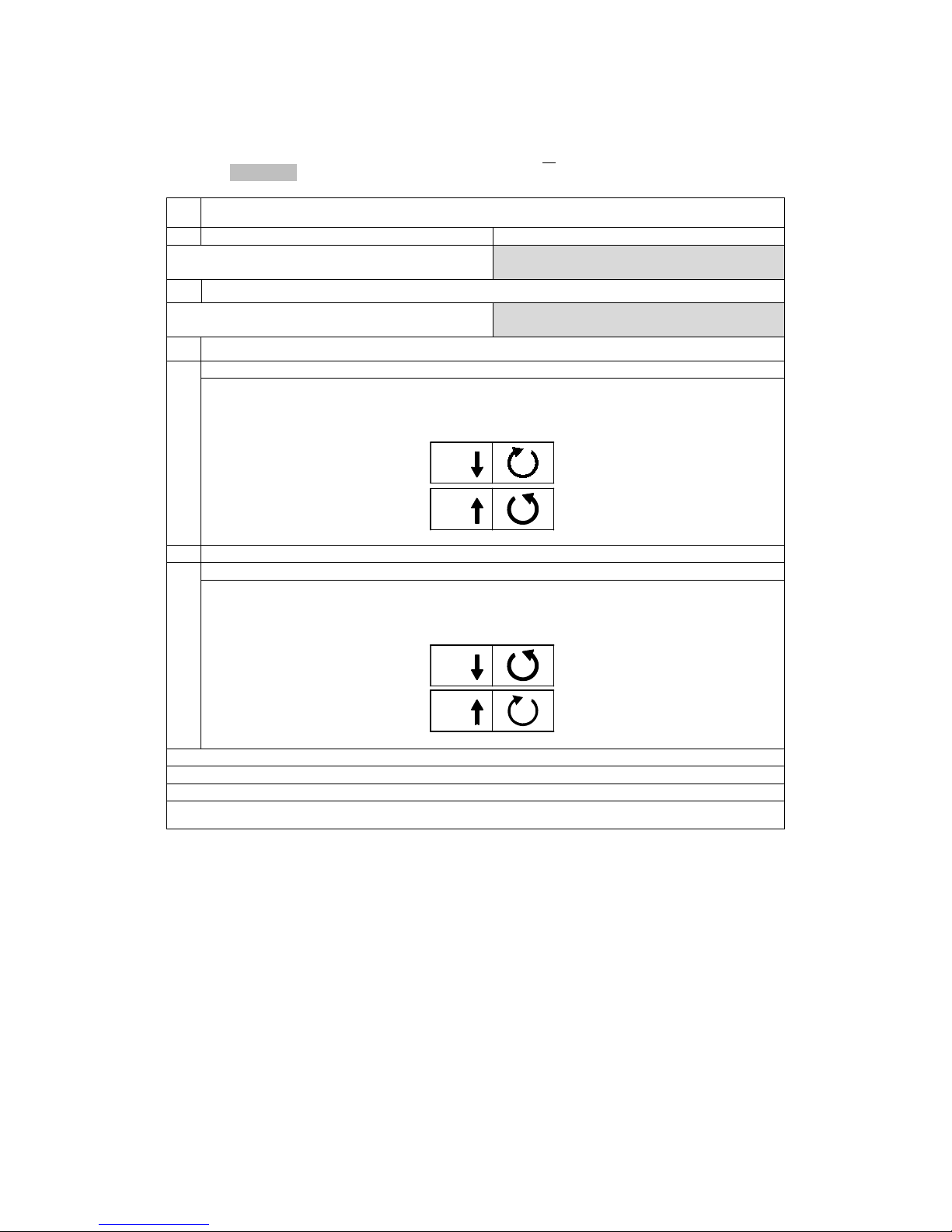
E93.0901EN.A Manual Consul+
85
14.1.4 ADJUSTMENT ACTIONS: GENERAL SCHEME
G
eneral scheme for adjustment of the gas valve(s). Check this scheme for an overview.
To complete all necessary adjustments in right order, follow case A or B top-down through the scheme (B involves
a few extra steps (grey fields)):
GENERAL SCHEME SETTING STEPS
case A
case B
continue ↓
first close screw [2], then set them in accordance with table 2
SWITCH TO SERVICE MODE
continue ↓
If burner doesn’t start, open (RIGHT*)
screw[2] ¼ turn extra
setting at maximum load
procedure 1
[▲] set burner at maximum load
measure CO2 at flue gas outlet;
use (RIGHT*) screw [2] to
match value with table 1 or the figure
setting at minimum load
procedure 2
[▼] set burner at minimum load
measure CO2 at flue gas outlet;
use (RIGHT*) screw [1] to
match value with table 1 or the figure
repeat procedure 1
repeat procedure 2
keep repeating until values match table values best or the figure
Water heater returns to NORMAL MODE after 40 min. OR by pressing [SERVICE] button
For an extensive description consult the next two sections (c hoos e whic h is appl icabl e, A or B):
14.2 Adjusting in case of a new water heater, or after service (case A)
14.2.1 GENERAL REMARK
For all adjusting ste ps und er A the m easured CO2 values sha ll be ac cording t able 1 or figures , no adj ustment is
necessary. If, however, larger deviations are m eas ured, adj us tment now must be made until the measured value
reaches the above-mentioned specifications.
14.2.2
ADJUSTING AT MAXIMUM LOAD
Adjust at maximum load by carrying out procedure 1, see p. 89.
14.2.3
ADJUSTING AT MINIMUM LOAD
Adjust at minimum load by carrying out procedure 2, see p. 89.
CO2
[2]
CO2
[2]
CO2
[1]
CO2
[1]
Page 86
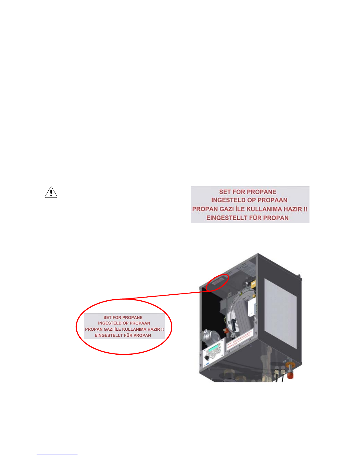
E93.0901EN.A Manual Consul+
86
14.3 Adjusting after gas valve replacement, or in case of gas conversion (case B)
14.
3.1
GENERAL REMARKS
All adjustments must result in CO2 percentages within the specification mentioned at the table or figure.
Adjus
ting at maximum load Consul+35 & Consul+55
The Consul+ heaters have single gas valves, see the drawings on page 86.
• First, turn setting screw [2] of the gas valve clockwise until you feel resistance. This means that the valve is
closed, do not try to tighten the screw any further.
• Now turn screw [2] counter clockwise (open), according to the number of turns in table 2 for the used water
heater and gas type.
After this, adjust at maximum load by carrying out procedure 1 on page 89.
If the burner doesn’t start up in service mode, turn screw [2] a quarter turn counter clockwise, and try again.
14.3.2
ADJUSTING AT MINIMUM LOAD CONSUL+35 & CONSUL+55
Adjust at minimum load by carrying out procedure 2 on p.89.
IMPORTANT: Toggle bet ween h igh f ire and lo w f ire to m ak e fine-tuning adjustments (adjusting the minimum set-
ting affects the maximum setting and contrariwise).
In case of gas conversion, paste the corres-
ponding sticker at the appropriate position in the
water heater.
C
hanging to another type of gas also needs
setting parameter “P4BD Gas type” (Di splay
D8).
This parameter is factory set to “0” for the use ofnatural gas G20 or G25.3.
Set to “1” when using propane (G31).
Page 87
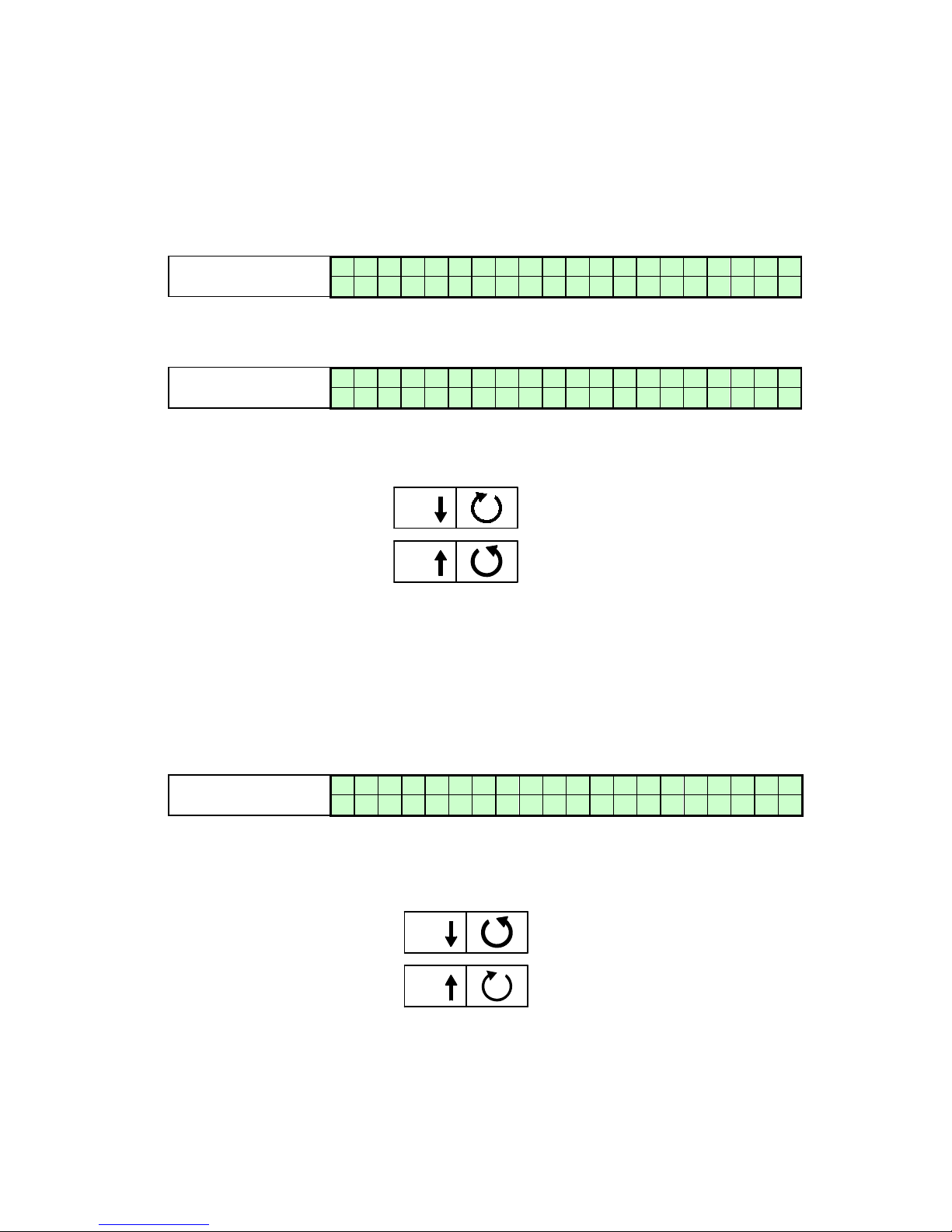
E93.0901EN.A Manual Consul+
87
14.4 Adjusting procedures
Procedures 1 and 2, referred to in the previous sections 14.2 and 14.3, are described here:
P
rocedure 1: adjust at maximum load
In case B (gas conversion or replacement of gas valve): consult § 14.3. before starting procedure 1 below.
C
arry out the next 4 steps:
1. Press [SERVICE] button for about 3 seconds.
Display message
W A T R H T R : S e r v i c e 2 6
%
> > > 1 2 3 . 4 ° C ( 1 2 3 . 4 ° C )
Water heater is activated and operates at service mode at 26% (minimum).
2. P
ress [▲] button until maximum load is reached:
Display message
W A T R H T R : S e r v i c e 1 0 0 %
> > > 1 2 3 . 4 ° C ( 1 2 3 . 4 ° C )
Water heater is activated and operates at service mode at 100% (maximum).
3. Meas
ure the CO
2
percentage at the flue gas outlet.
4. By setting screw [2], adjust the gas valve to obtain the CO
2
value of table 1 or figure.
Decrease CO
2
percentage Turn screw [2] right (clockwise)
Increase CO2 percentage Turn screw [2] left (counter clockwise)
The service operation of the water heater will be active for 40 minutes.
After this period the water heater will return to normal operation.
P
rocedure 2: adjust at minimum load
In case B (gas conversion or replacement of gas valve): consult § 14.3. before starting procedure 2 below.
C
arry out the next 3 steps:
1. Press [▼] button until minimum load is reached.
Display message
W A T R H T R : S e r v i c e 2 6
%
> > > 1 2 3 . 4 ° C ( 1 2 3 . 4 ° C )
Water heater is activated and operates at service mode at 26% (minimum).
2. Meas
ure the CO
2
percentage at the flue gas outlet.
3. By setting screw [1], adjust the gas valve to obtain the CO
2
value of table 1 or figure.
Decrease CO2 percentage Turn screw [1] left (counter clockwise)
Increase CO2 percentage Turn screw [1] right (clockwise)
The service operation of the water heater will be active for 40 minutes.
After this period the water heater will return to normal operation.
CO2
[2]
CO2
[2]
CO2
[1]
CO2
[1]
Page 88
E93.0901EN.A Manual Consul+
88
PUTTING THE WATER HEATER OUT OF OPERATION
It is recomm ended to have the water heat er operational all year round to prevent a ny frost damage dur ing the
winter and/or rotating parts getting jammed during other times of the year (built in water heater safety features).
15.1 Out of operation: on/off function
To be used when the applianc e must be put out of operation for a long per iod because of a defect or another
safety risk.
Act as follows:
• Disconnect or switch off the tank therm ostat and /or ot her ex terna l co ntroller s fr om the wat er heater . T he
pump and fan will stop after a short time.
• Switch off the water heater by pressing the [ON/OFF] button for six seconds.
• Make sure the following display screen is visible.
Display message
B o i l e r o f f
Properties of the ‘off’ function:
• The keys do NOT respond and the menu is NOT accessible.
• The burner does NOT respond to an external heat demand.
• The water heater CAN, however, be switched on again by pressing the [ON/OFF] button.
• Pump(s), fan(s) and casca de (if applicable) are operatio nal, and so are both re circulation protection (if
applicable) and frost protection.
• To reactivate the water heater, switch on the burner by pressing [ON/OFF] for six seconds again.
The frost protection module can still activate the burner
(s).
To prevent
this, switch off this protection or put the water heater in ‘power off’ mode (next paragraph).
15.2 Out of operation: power off
To assure that the water heater cannot become active at all anymore, power should be cut off completely.
Act as follows:
• Disconnect or switch off the tank therm ostat and /or ot her ex terna l co ntroller s f rom the wat er heater . T he
pump and fan will stop after a short time.
• Switch off the water heater by pressing the [ON/OFF] button for six seconds.
• Make sure the following display screen is visible.
Display message
B o i l e r o f f
• Switch off the electrical power supply of the water heater (remove connection f rom the wall socket, or
switch off the main power).
• Close the gas valve / gas supply.
• In case of possible frost damage: drain both the water heater and the DHW system.
• NOTICE: Before draining the water heater, first s tart draining the D HW system and su bsequently open
also the two drains of the water heater.
Page 89
E93.0901EN.A Manual Consul+
89
FAULT CODES, BLOCKI NG CO DE S
IMPORTANT:
To avoid electric shock s, disconnect electric al supply before perf orming troubles hooting. To
avoid burns, allow the unit to cool before performing troubleshooting.
Be aware that a fault cod e is an indicat ion tha t the un it or the syst em needs atten tion. When
repeatedly having faults these should not be neglected.
The first step is to c hec k if the unit is ins talled ac cord ing t o the instruc tions . If not, f irst m ake
sure the installation complies with the installation manual.
Always check the fuses on the control board before replacing any major components. A blown
fuse can prevent the controller or other components from operating.
Most faults can also be caused by a bad wiring and/or connections, even if it is not specifically
mentioned. With ever y fault it is wise to check wiring and connections (at both ends) that
connect to the safety device/component that generates the fault.
16.1 Lock-out codes
A lockout means that the water heater needs a manual reset to start operating again.
When the water heater is in lockout the backlight of the display is blinking on and off.
Explanation >
9 9 9 , 5 : h r s
= time elapsed after fault message.
Explanation >
P u m p 1 o
n
= status of the pump during fault.
Display message
F8
F a i l e d b u r n e r s t a r t p u m p o n 9 9 9 , 5 h r s Reason
Water heater not operational after four starting attempts.
Cause: No spark.
Corrective action:
Check the ignitor/ignition electrode and replace/clean if necessary.
Check the state of the ceramic insulator. A small crack can prevent the spark to form at the
end of the electrode.
Check the distance between the electrode pin, earth pin and burner.
Check the state of the ignition cable and replace if necessary.
Check the state of the earth wire/connection of the ignitor and replace if necessary.
Check the state of the sparkplug cap and replace if necessary.
Check power supply. Voltage must be 230 Vac nom.
Check for proper electrical grounding of unit.
Bad ignition transformer. Replace the burner control of the unit.
Cause: Ignition spark is present, but no flame results.
Corrective action:
Check if all gas valves in the supply line are completely open.
Check if there is no air in the gas supply (start-up new systems).
Check if the gas valve opens. When there is power supply to the gas valve, but the valve does
not open, the gas valve must be replaced.
Check if the gas valve opens. When there is no power supply to the gas valve check the gas
valve wiring/connections .
Check if the gas valve settings are correct and adjust if necessary.
Check if the gas pressure is correct and sufficient.
Check if the air supply is open/not blocked.
Cause: Flame, but not enough ionisation to establish the flame.
Corrective action:
Check the ignitor/ignition electrode and replace/clean if necessary.
Check the state of the ceramic insulator.
Check the distance between the electrode pin, earth pin and burner.
Check the state of the ignition wire (also the ionisation wire) and replace if necessary.
Check the state of the earth wire/connection of the ignitor and replace if necessary.
Check for proper electrical grounding of unit.
Check power supply. Voltage must be 230 Vac nom.
Check the state of the sparkplug cap and replace if necessary.
Page 90
E93.0901EN.A Manual Consul+
90
Display message
F10
F a l s e f l a m e s i g n a l p u m p o n
9 9 9 , 5 h r s
Reason
Flame signal detected, while water heater should not fire
for operation.
Cause: The flame detection circuit detects a flame which is not supposed to be present.
Corrective action:
Check the ignition/ionisation electrode and make sure it is clean (or replace it).
Check the power supply voltage for a correct polarity.
Check the power supply for bad frequency or voltage peaks.
Check external wiring for voltage feedback.
Check the internal wiring for bad connections.
Check if the gas valve is closing correctly.
Replace the burner control.
Display message
F11
F a n s p e e d i n c o r r e c t p u m p o n
9 9 9 , 5 h r s
Reason
Actual fan speed differs from the unit rpm set point.
Cause: An incorrect fan speed is detected.
Corrective action:
Check the 4-wired wiring and connections at the fan and at the main control board.
Check the 3-wired power supply wiring and connections at both ends.
Replace the fan.
Replace the main control board.
Display message
F9
F l a m e l o s t p u m p o n 9 9 9 , 5 h r
s
Reason
Flame signal lost during operation.
Cause: Bad gas supply pressure.
Corrective action:
Be aware that the specified gas pressure must be met during all operation conditions.
Check if all gas valves in the supply line are completely open.
Check if the dirt filters mesh in the gas valve inlet is clean.
Check if the external dirt filter in the gas supply line is not blocked.
Check if an external gas pressure regulator is selected/installed correctly.
Check the gas pressure that is supplied to the building > call the supplier if necessary.
Cause: Bad gas valve or gas valve settings.
Corrective action: Check and set gas valve settings.
Cause: Bad electrode, electrode wiring/connection (bad ionisation signal).
Corrective action:
Check ionisation signal.
Check the ignitor/ignition electrode and replace/clean if necessary.
Check the state of the ceramic insulator.
Check the distance between the electrode pin, earth pin and burner.
Check the state of the ignition wire (is also ionisation wire), and replace if necessary
Check the state of the ignitor earth wire/connection and replace if necessary.
Check for proper electrical grounding of unit.
Cause: Bad flue gas and/or air supply system.
Corrective action:
Check if the design of the flue gas and air supply system complies with the max. combined re-
sistance as specified.
Check if the flue gas and air supply system is installed according a good installation practice
by a skilled install e r.
Check all seals in the flue gas and air supply system.
Cause: External factors.
Corrective action:
Check if there were extreme weather/wind conditions when the fault occurred.
Check if the water heater room pressure is equal to the pressure at the position of the flue gas
outlet (when combustion air is drawn from the water heater room).
Page 91
E93.0901EN.A Manual Consul+
91
Display message
F1
F l o w h i g h T e m p p u m p o n 9 9 9 , 5 h r
s
Reason:
Max. flow temperature exceeds limitation (lock-out) value.
Cause:
The water flow is restricted.
Corrective action:
Check functioning of the pump.
Check/open all valves that might restrict the water flow through the unit.
Check for an external system pump that influences flow through the unit.
Check if the system resistance exceeds the spare capacity of the unit pump.
Display message
F0
F l o w s e n s o r e r r o r p u m p o n 9 9 9 , 5 h r
s
Reason:
Flow sensor is not detected.
Cause:
Bad wiring/connection in the flow sensor circuit.
Corrective action:
Check for loose wiring/connections in the flow sensor circuit.
Cause:
Bad temperature sensor causing a fault signal.
Corrective action:
Replace flow sensor.
Display message
F16 F l o w R e t u r n d t f a u l t p u m p o n 9 9 9 , 5 h r s
Reason:
Temperature difference between flow and return exceeds limitation
value, or 'dT block or delta direct block' has occurred three times.
Cause:
The water flow through the unit is too low.
Corrective Action:
Check functioning of the pump.
Check/open all valves that might restrict the water flow through the unit.
Check for an external system pump that influences the flow through the unit.
Check if the system resistance exceeds the spare capacity of the unit pump.
Make sure the heat exchanger is clean. Heat exchanger fouling (partly blockage) will increase
the resistance causing the water flow to drop.
Display message
F6
F l u e s e n s o r e r r o r p u m p o n 9 9 9 , 5 h r
s
Reason
Flue sensor is not detected by the water heater PCB.
Cause:
Bad wiring/connection in the flue gas sensor circuit.
Corrective action:
Check for loose wiring/connections in the flue gas sensor circuit.
Cause:
Bad temperature sensor causing a fault signal.
Corrective action:
Replace flue gas sensor.
Page 92
E93.0901EN.A Manual Consul+
92
Display message
F7
F l u e t e m p t o o h i g h p u m p o n 9 9 9 , 5 h r
s
Reason
Flue gas temperature exceeded 3 times limitation value within
a certain period.
Cause: Heat exchanger polluted and not able to transfer enough heat to system water.
Corrective action:
Check and clean heat exchanger.
Cause: Bad flue gas sensor or sensor connection (partly shorted).
Corrective action:
The sensor is of the type NTC. This means if the temperature rises, the resistance lowers. A
partly shorted sensor will drop its resistance and therefore 'measure' a raise in temperature
when actually there is none.
Check for moist in the sensor connections or replace sensor.
Cause: There is no water in the unit while firing.
Corrective action:
This is an unlikely situation while all the safeties for checking the water presence didn't detect
anything. Only a lot of air in the system/unit (under pressure) can cause the water pressure
switch to switch while no water is present. Also the water leak detection
did not react. Bleed all air from the unit so the heat from combustion can be transferred to the
water and won't disappear through the flue system.
Cause: Heat exchanger failure.
Corrective action:
This is an unlikely situation but when there is severe damage to the heat exchanger, the com-
bustion product will not be able to transfer all heat to the system water. The heat that is not
transferred will convert to an increased flue gas temperature.
Display message
F12
p r o g r a m m i n g e n d p u m p o n
9 9 9 , 5 h r s
Reason
Programming of the parameters completed successfully.
Cause: Programming of the parameters completed successfully.
Corrective action:
This message occurs to confirm the end of programming. Pressing RESET will return the unit
in normal operating status.
Display message
F13
P a r a m / H a r d w f a u l t
p u m p o n
9 9 9 , 5 h r s
Reason
Failure during programming of the parameters.
Cause: Programming of the parameters NOT successfully completed
Corrective action:
Unit is not in standby mode (fan must not run during programming).
Check programming wire and connections and try again.
Check if the software complies with the PCB.
Replace the programming wire.
Replace the display PCB.
Display message
R e t u r n h i g h T e m p F1
p u m
p o
n
9 9 9 , 5 h r s
Reason:
Maximum return temperature exceeds limit value.
Cause: Systems that pre-heats the water heater return temperature too much/high.
Corrective Action:
Reduce pre-heat temperature of external heat source.
Cause:
The need for heat in the system suddenly drops causing hot return water to the heater.
Corrective Action:
Dampen external heating system control to prevent sudden heater temperature rise.
Page 93
E93.0901EN.A Manual Consul+
93
Display message
F3
R e t u r n s e n s o r e r r o r p u m p o n 9 9 9 , 5 h r
s
Reason
Return sensor is not detected by the water heater PCB.
Cause: Bad wiring/connect ion in the return sensor circuit.
Corrective action: Check for loose wiring/connections in the return sensor circuit.
Cause: Bad temperature sensor causing a fault signal.
Corrective action: Replace return sensor.
Display message
F19
S i p h o n s w i t c h p u m p o n
9 9 9 , 5 h r s
Reason
Siphon pressure switch detects high pressure
in the flue/siphon system.
Cause:
There is too much resistance in the flue gas circuit causing high pressure in the heat exchanger at the flue gas side.
Corrective action:
Check if the flue gas system is blocked.
Extreme failing of the heat exchanger also causes the resistance to rise. Check the state of
the heat exchanger and clean if necessary.
Check the flue gas system diameter & length (most likely in a new system).
Cause:
The condensate drain system is blocked. The condensate will build up above the measuring
point of the pressure switch and creates a static pressure larger than the measuring point.
Corrective action:
Check if the condens ate drain hos e bet ween the he at exc hanger and the siphon i s open, so
the condensate can flow freely to the siphon.
Check if the siphon is free of debris that might block the condensate flow and clean the siphon
if necessary.
Check the condensate drain hose between the siphon and the condensate drain point in the
external installation. Condensate must be able to flow freely.
Cause:
The condensate drain hose must have an open connection to the external system. If not, pres-
sure fluctuations in the building drainage system can have effect on the pressure in the heat
exchanger of the water heater.
Corrective action:
Make sure that there is an open connection between the siphon hose and the drainage system
of the building installation. The condensate should flow in the drainage system through a freely
"breathing" connection, so pressure fluctuations of the external drainage system cannot affect
the pressure in the heat exchanger of the water heater.
Cause: Blockage of the pressure signal hose going to the pressure switch.
Corrective action: Check the pressure signal hose and clean or replace if necessary.
Cause: Bad pressure switch causing a fault signal.
Corrective action:
Replace the pressure switch.
Cause: Bad wiring/connect ion in the pr ess ur e switch circuit.
Corrective action:
Check for loose wiring/connections in the pressure switch circuit.
Display message
F17
W a t e r h i g h l i m i t p u m p o n
9 9 9 , 5 h r s
Reason
Maximum thermostat exceeds limitation value.
Cause: The water flow is restricted.
Corrective action:
Check functioning of the pump.
Check/open all valves that might restrict the water flow through the unit.
Check for an external system pump that influences the flow through the unit.
Check if the system resistance exceeds the spare capacity of the unit pump.
Page 94
E93.0901EN.A Manual Consul+
94
16.2 Blocking codes
The display is not blinking, but is lightened up during the blocking period.
The water heater is blocking an action, because of an extraordinary situation. This action will be continued after
eliminating the extraordinary situation.
Display message
A n t i c y c l e t i m e
9 9 9 , 5 h r
s
Reason
The heater received a heat demand too fast after the last demand.
Cause: Opening and immediately thereafter closing of the external thermostat.
Corrective action:
Controlled water flow cools down too quic kly after loss of heat demand.
Controlled water flow heats up too quickly after start of heat demand.
Immediately opening and closing of the external thermostat. Check switching differential of the
ON/OFF thermostat.
Controller settings need to be changed. Be aware that the standard settings work fine for all
common systems. When anti-cycling is active, because of immediate heating or cooling of the
controlled water flow/temperature, it concerns an unconventional system.
Display message
C a s c a d e B l o c k 9 9 9 , 5 h r s
Reason
One of the water heaters of the cascade is in a lock-out.
Cause:
The unit is programmed in such a way that none of the heaters in a cascade will fire, if one
has a lockout. One unit has a lockout and therefore the whole cascade is blocked.
Corrective action:
Troubleshoot the fault of the unit in lock-out.
Display message
D e l t a D i r e c t b l o c k
9 9 9 , 5 h r
s
Reason
Temperature difference between flow and return has exceeded the
blocking value
Cause: The water flow through the unit is too low.
Corrective action:
Check functioning of the pump.
Check/open all valves that might restrict the water flow through the unit.
Check for an external system pump that influences the flow through the unit.
Check if the system resistance exceeds the spare capacity of the unit pump.
Make sure the heat exchanger is clean. Heat exchanger fouling (partly blockage) will increase
the resistance causing the water flow to drop.
Display message
F l o w h i g h D H W
9 9 9 , 5 h r
s
Reason:
Setpoint return (tank)temperature DHW (S3) is higher than setpoint
heating = flow temperature (S1)
Cause: Wrong setting of parameter: P6BA Heating setpoint below P6CA DHW setpoint
Corrective action:
Adjust the heating setpoint through the display: menu, settings, heating setpoint
Display message
F l o w t e m p h i g
h
9 9 9 , 5 h r
s
Reason:
Flow temperature has exceeded the blocking temperature, but it has
not exceeded the lock-out value.
Cause: The water flow is restricted.
Corrective action:
Check functioning of the pump.
Check/open all valves that might restrict the water flow through the unit.
Check for an external system pump that influences the flow through the unit.
Check if the system resistance exceeds the spare capacity of the unit pump.
Page 95
E93.0901EN.A Manual Consul+
95
Display message
F l u e t e m p h i g h 9 9 9 , 5 h r
s
Reason
Flue gas temperature has exceeded the limit.
Cause: Heat exchanger polluted and not able to transfer enough heat to the system.
Corrective action: Check and clean heat exchanger.
Cause: Bad flue gas sensor or sensor connection (partly shorted.)
Corrective action:
The sensor is of the type NTC. This means when the temperature rises, its resistance de-
creases. A partly shorted sensor will drop its resistance and therefore ‘measure’ a raise in
temperature when actually there is none.
Check for moist in the sensor connections or replace the sensor.
Cause: There is no water in the unit while firing.
Corrective action:
This is an unlikely situation while all the safeties for checking the water presence didn't detect
anything. Only a lot of air in the system/unit (under pressure) can cause the water pressure
switch to switch while no water is present. Also the water leak detection
did not react. Bleed all air from the unit so the heat from combustion can be transferred to the
water and won't leave through the flue system.
Cause: Heat exchanger failure.
Corrective action:
This is an unlikely situation but when there is severe damage to the heat exchanger, the com-
bustion product will not be able to transfer all heat to the system water. The heat that is not
transferred will convert to an increased flue gas temperature.
Display message
G e n B l o c k 9 9 9 , 5 h r
s
Reason
General blocking circuit is activated during operation (general blocking contacts 7-8).
Cause: The circuit connected to the general blocking terminals is not closed.
Corrective action:
Check all external components that are connected to the general blocking terminals and check
why the contact is not closing during heat demand.
Cause if used with flow switch: The water flow through the unit is too low.
Corrective action:
Check functioning of the pump and the flow switch.
Check/open all valves that might restrict the water flow through the unit.
Check for an external system pump that influences flow through the unit.
Check if the system resistance exceeds the spare capacity of the unit pump.
Make sure the heat exchanger is clean. Heat exchanger fouling (partly blockage) will increase
the resistance causing the water flow to drop.
Display message
L i n e f a u l t p u m p on9 9 9 , 5 h r s
Reason
Bad power supply
Cause: The supplied power does not comply with the specifications.
Corrective action:
Check if the power supply is connected correctly to the unit.
Check the voltage and frequency (should be Life Neutral, Gnd > 230 Vac / 50 Hz).
Make sure there is no signal failing or voltage peaks in the power supply.
Display message
R e t u r n t e m p h i g h 9 9 9 , 5 h r
s
Reason
Return temperature has exceeded the blocking temperature, but it
has not exceeded the lock-out value.
Cause: Systems that pre-heats the water heater return temperature too much/high.
Corrective action: Reduce pre-heat temperature of external heat source.
Cause: The need for heat suddenly drops causing hot return water to the water heater.
Corrective action:
Dampen external heating system control to prevent sudden heater temperature rise.
Page 96
E93.0901EN.A Manual Consul+
96
Display message
T 2 - T 1 h i g h
9 9 9 , 5 h r
s
Reason
Difference between T2 and T1 has exceeded the blocking value
which has been set in the parameters. (return temp higher than flow)
Cause:
The water flow through the unit is too low.
Corrective action:
Check functioning of the pump.
Check/open all valves that might restrict the water flow through the unit.
Check for an external system pump that influences flow through the unit.
Check if the system resistance exceeds the spare capacity of the unit pump.
Make sure the heat exchanger is clean. Heat exchanger fouling (partly blockage) will increase
the resistance causing the water flow to drop.
Display message
W a t e r p r e s s u r e f a u l t 9 9 9 , 5 h r
s
Reason
Water pressure is too low or high.
Cause:
The water pressure in the system is too high.
Corrective action:
Check if the system pressure is too high after (re)filling.
Make sure that there is a pressure relief valve and expansion vessel installed in the system,
according to the applicable standards.
Check if there is an open connection between the unit and the relief valve plus expansion vessel.
Be aware that if the unit is installed in the basement of a tall building, only the static pressure
of the water column above the units can raise above the maximum allowable limits. Make sure
that this is not the case.
Cause:
The water pressure in the system is too low.
Corrective action:
Check if there is no leakage in the system that causes the pressure to drop. Fix any leakage
and fill the system.
Check if there is an external system pump that sucks water through the water heater, causing
an under pressure (bad installation design).
Display message
W A T R H T R : T 3 E x t e r n a l > > > : 6 0 . 0 ° C ( - 3 0 . 7 ° C )
Reason:
T3 external tank sensor is not connected to the terminals.
Cause:
The sensor is not connected to the terminal, or the wire is broken. The sensor is malfunctioning.
Corrective Action:
Connect the sensor to the terminals 3 and 4.
Check the wires from the sensor to the terminals.
Check the sensor on resistance 10K at 25°C.
Page 97
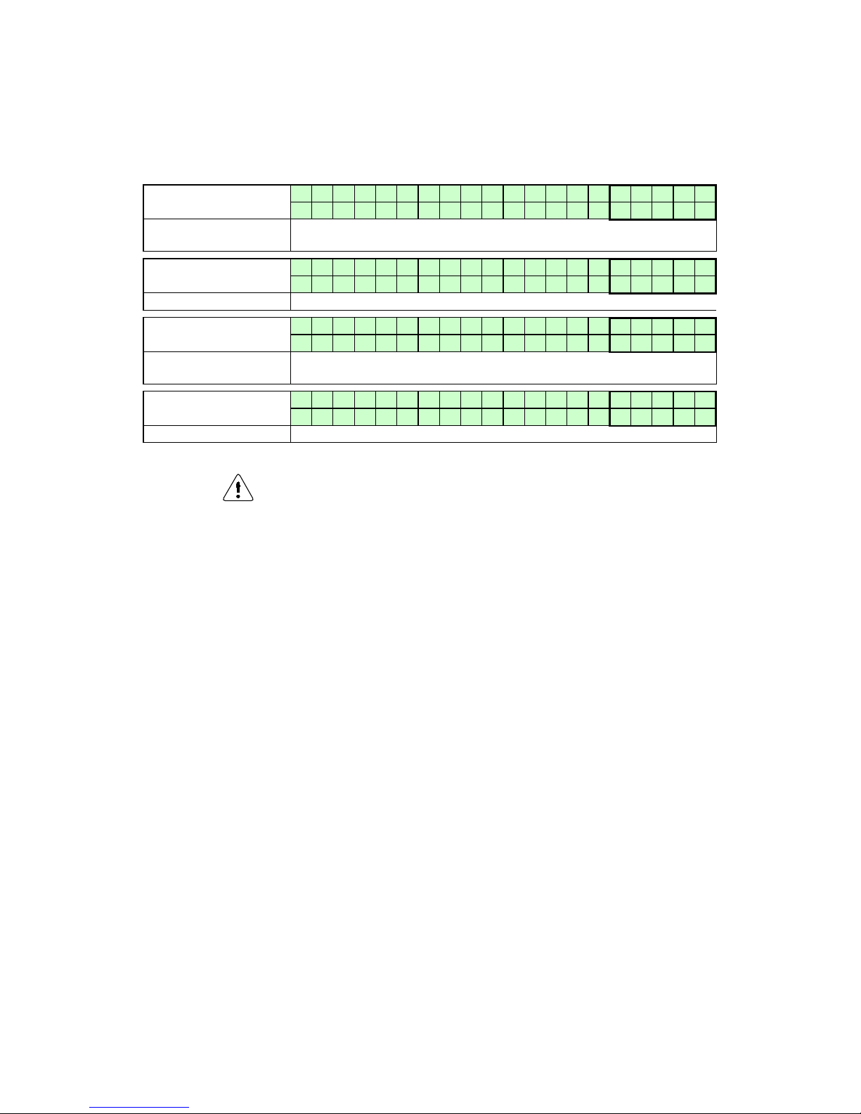
E93.0901EN.A Manual Consul+
97
16.3 Maintenance attention function
The display shows alternately the base screen and this message, while backlight is blinking.
The water heater is operating, but will count the exceeding hours.
A parameter must be changed, after service, to remove this message.
Display message
N e e d s M a i n t e n a n 0 .
0
I g n i t i o n c y c l e s h r s
Reason
Maintenance option of total amount of ignition cycles has been
reached.
Display message
N e e d s M a i n t e n a n 0 .
0
D a t e h r s
Reason
Maintenance option of the date has been reached.
Display message
N e e d s M a i n t e n a n 0 .
0
B u r n i n g h o u r s h r s
Reason
Maintenance option of total amount of burning hours has been
reached.
Display message
N e e d s M a i n t e n a n 0 .
0
A l l h r s
Reason
One of the abovementioned maintenance options has been reached.
This function/mes sage is standard not activated, but c an be acti-
vated/set by a trained engineer. T his function does not overru le
the need for annual maintenance. The end user is always respon-
sible for arranging annual maintenance.
Page 98
E93.0901EN.A Manual Consul+
98
MAINTENANCE
17.1 General
For a good, safe and long-time operation of the water heater, it is advised to carry out maintenance and service at
least every twelve months. Both safety and life time will thus be improved. Omission of pr ev ent iv e a nd c orr ect ive
maintenance can have warranty consequences.
Maintenance and inspection of the water heater should be carried out at the following occasions :
• When a number of similar error codes and/or lock-outs appear.
• At least every twelve months’ maintenance must be done to ensure safe and efficient operation.
Damage caused by lack of maintenance will not be covered under warranty.
MAINTENANCE REMINDER FUNCTION.
See last page.
BE AWARE: This function is s tand ar d t ur ne d OFF. We offer this progr am mable function to the installer to us e as
a reminder. Because it c oncerns a free program mable function t he use of it cannot be used as an argum ent in
warranty cases. Our units must be maintained every twelve months whatever the settings/working of this function.
It is and remains the responsibly of the end user to have the unit maintained every twelve months.
For more information about this maintenance mode see section 10.13 ‘Setting the maintenance specifications’ on
page 615.
Service intervals
The normal service interval for the water heater is o nce a year. Ever y year the water h eater should be cleaned
and checked, accordi ng to the m aintenance proc edures. If there is doubt wh ether the water heater is operating
with the correct water and/or combustion air quality, it is advised that a first check is executed after already half a
year. This to determine the frequency of the future service intervals. The maximum interval between two services
can be a year.
INSPECTION AND MAINTENANCE MUST BE EXECUTED FOR A SAFE AND EFFICIEN T OPERATION OF THE WATER HEATER.
17.2 Inspection & maintenance
Inspection, maintenance and the replacement of water heater parts should only be done by a skilled service engineer. Apart from the maintenance proceedings it is advised to have a log chart for every water heater that describes
the following aspects:
• Serial number
• Date and time of maintenance
• Name of maintenance engineer
• Which parts were exchanged during maintenance
• Which settings (software) were changed during maintenance
• Special remarks / findings
• Future aspects that need extra attention
• Additional aspects: measurement reports, complaints by the (end)-user, lock-out codes, etc.
During maintenance the following parts and aspects of the water heater should be checked and inspected.
NOTICE: Before starting to work on the water heater:
• Switch off the electrical power to the water heater (service switch and/or unplug water heater)
• Close the gas valve to block gas supply to the water heater
Page 99
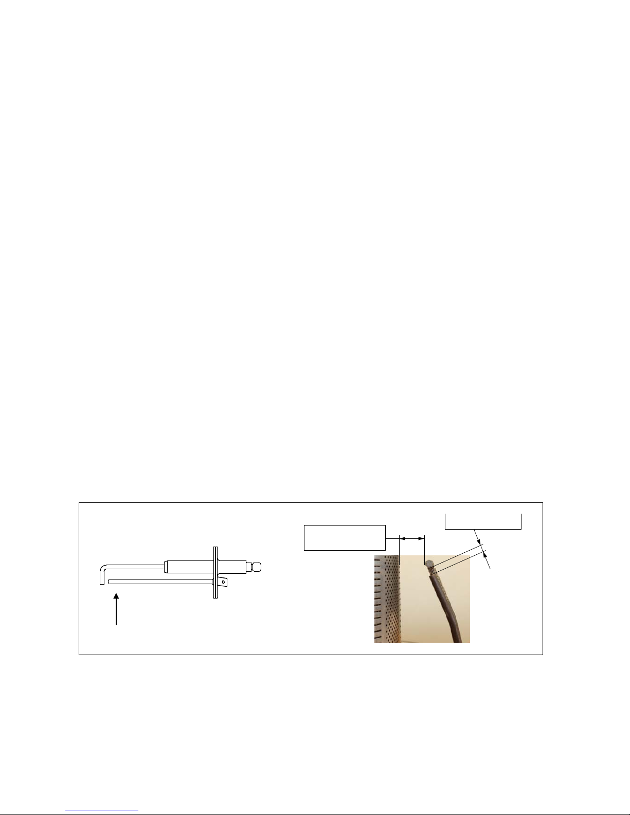
E93.0901EN.A Manual Consul+
99
Customer comments
Comments and remarks from the customer should be analysed and used to fin d possib le causes for any occurring
problems and complaints.
Service history
The operational and fault history (total amount and since the last service) of the water heater can be retrieved with
the help of a computer, correct software and an interface cable. This information can be used to specify the maintenance and service proceedings in relation to the water heater (parts).
Flue gas & air supply
The flue gas pipes and the air supply pipes must be checked for gas tightness. Also check if the mounting of these
pipes is correct, saf e and not damaged. Check the roof top of the water heater hou s ing f or s igns of water l eak age
and traces of water coming from the air supply pipe, the air vent or any condensate coming from the flue gas pipes.
Gas supply & safeties
The gas pipes mus t be checked f or gas tightnes s. Also c heck if the mounting of these p ipes is c orrect, saf e and
not damaged. Any built-in safeties should be checked for a correct functioning.
Remove complete burner unit
The complete burner unit consist s of the f an, the burn er plate and t he int erna l bu rner. T o rem ove th is part for an
internal heat excha nger check : remove the 6 x M6 nuts and the i gnition cable. A fter this take out the complete
burner unit by moving it forward out of the water heater housing. NOTICE: watch out for the burner plate insulation
that it won’t be dam aged during this operati on. While removing the c omplete burner unplug both electric al and
controlling cables of the f an. Af ter all th is, disassemble the air/gas m ixing box on the suc tion s ide of the fan and
check the blade wheel of the fan.
Burner
Check the burner surface to see if it has damages, signs of oxidation and/or is cracked. When the burner surface
is damaged, the burner m ust be replaced. The burner c an be cleaned by using a sof t non-metallic brush. The
dust can be removed with a vacuum cleaner or pressurized air.
Ignition / ionization electrode
When the complete burn er is rem oved, it is also very easy to c heck the ign ition electrode. First check if the distances between the electrodes and between the electrode and the burner are according to the graph below. When
these are not correct, tr y to bend t he e lec trodes in the right position. Notice: the elec trodes un der go h ig h tem peratures, therefore the electr odes become hard and are difficult to bend. W hile being bent, used electr odes might
break or burst. Check the electrode, after bending, for any tear/crack and signs of oxide. When they are
burst/cracked or oxidized, replace the electrode. A lso replace the e lectrode when there is a crack in the ceram ic
insulation of the electrode. When the electrode is to be replaced, also the gasket should be renewed.
Burner door gaskets
When these gaskets have changed colours at some parts, the rubber has cured and/or has damages, these gaskets must be replaced. Notice: only use the gaskets that are supplied by the water heater manufacturer.
D = 8 - 10 m
m
D = 0.31
5 - 0
.39
3 in
ch
D
3
.5 m
m / 0.
14
in
c
h
Point of view in next picture →
Page 100
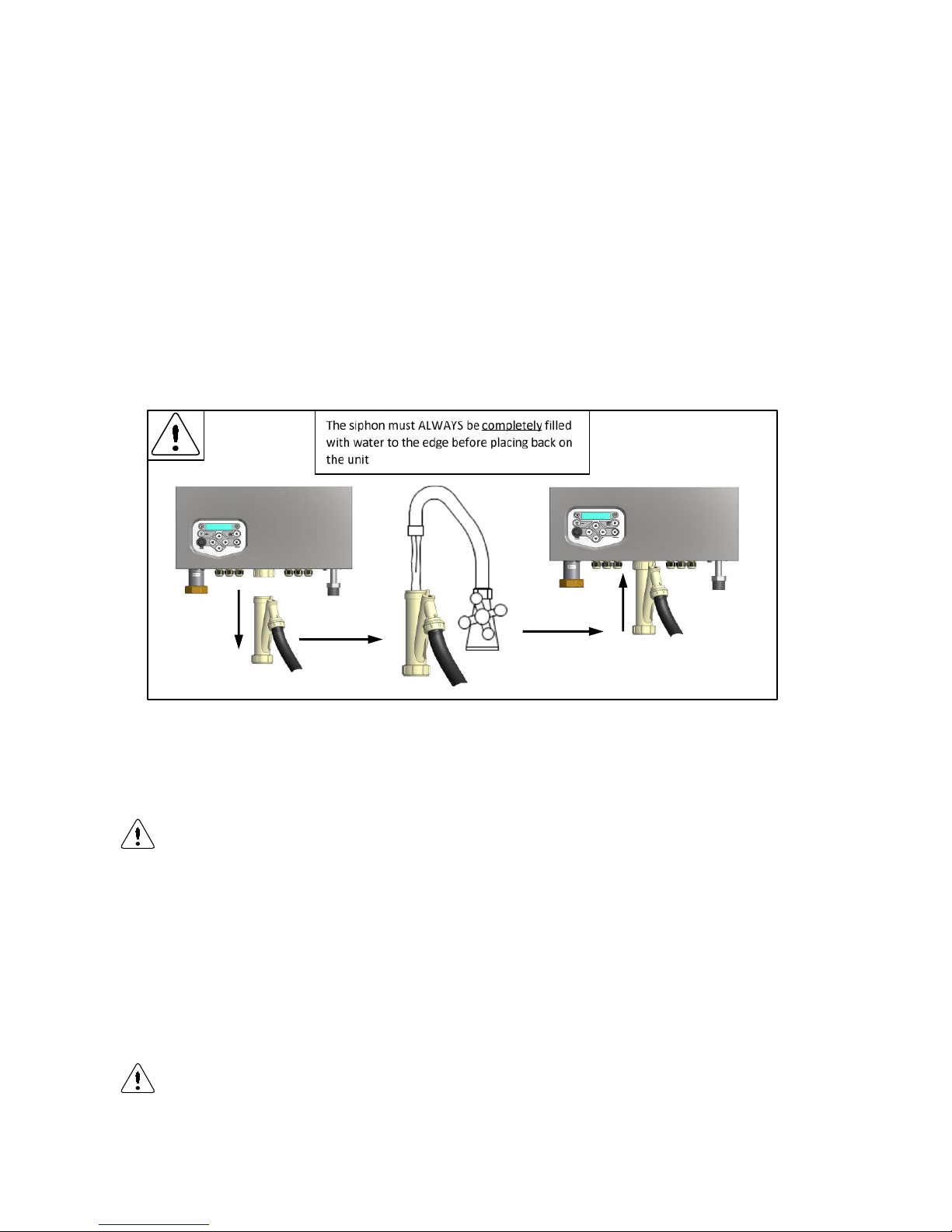
E93.0901EN.A Manual Consul+
100
Fan
When the fan blades are polluted a nd dirty, caref ully clean the b lades with a sof t brush. Notice: Do not use too
much force on the blades or else t he fan might be out of b alance and run irregularl y, causing noises and fan
failures. Check the fan also for any water damages. In doubt always replace the fan of the water heater.
Insulation
The insulation of the he at exchanger ( located on th e rear wall inside th e heat exchanger and burner door) m ust
be inspected. If this insula tion disk shows any signs of (water) damage or degradat ion it should be exchang ed.
Also check if there are any indications of a high condensate level in the burner room (caused by a blocked siphon)
that might have wetted th e rear wall insulat ion. When this has happ ened the rear wa ll insulation should a lso be
replaced.
Only use the insulation disk that is supplied b y the water heater manufacturer.
The same procedure must be applied on the insulation and gaskets fitted on the burner door.
Siphon
Disassemble the sip hon and clean e very part of it. C heck the siphon connection of the heat exchanger f or any
blocking or pollution and c l ean i t (if nec es sary). Check the functioning of the s ipho n b y pouri ng c lean t a p water in
the burner room (when burner door is removed). This water wi ll exit the heat exchanger b y the siphon. Notice:
Don’t wet the rear wall insulation.
Heat exchanger and burner room
After the removal of the complete burner unit, check if there is any debris and dirt in the heat exchanger. The coils
of the heat exchanger ca n be cleane d b y using a non-metallic brush. After this th e dirt and dust can be rem oved
with a vacuum cleaner and by flushing the burner room with w ater. Don’t forget afterwards to c lean the siphon
once again.
Cleaning the burner room with acid or alkali products is prohibited.
G
as/air ratio
With every service check and/or maintenance of the water heater always check the gas/air ratio by measuring the
CO
2
percent age (flue gas) at the maximum and minimum load of the water heater. If nec essary adjust these
values, see for information chapter 14 “Adjusting and setting the burner”.
Pu
mp
Check the electrical parts and the motor of the pump for a correct functioning. The pump must generate a sufficient
water flow over the (heat exchanger of the) water heater. When the pump produces noise, is operational for more
than five years or has signs of water leakage it is recommended to replace the pump as a precaution.
W
hen defects and abnormalities are foun d by the service engine er during service and m aintenance
and these are not repairable, this information should be reported to the owner/end-user of the installation. Also the owner/end-user should be advised how to fix these defects and these defects should be
reported in the service report / log file of the water heater.
 Loading...