

Page 1
Design Guide
No. 160, 8/1/05
AirHeat
Burners
AH-MA Series
Version 2
Page 2
C
OPYRIGHT
Copyright 2004 by Eclipse, Inc. All rights reserved worldwide.
This publication is protected by federal regulation and shall
not be copied, distributed, transmitted, transcribed or
translated into any human or computer language, in any form
or by any means, to any third parties, without the express
written consent of Eclipse, Inc., Rockford, Illinois, U.S.A.
D
ISCLAIMER NO TICE
L
IABILITY AND
WARRANTY
We reserve the right to change the construction and/or
configuration of our products at any time without being
obliged to adjust earlier supplies accordingly.
The material in this manual is believed adequate for the
intended use of the product. If the product, or its individual
modules or procedures, are used for purposes other than
those specified herein, confirmation of their validity and
suitability must be obtained. Eclipse, Inc. warrants that the
material itself does not infringe any United States patents. No
further warranty is expressed or implied.
We have made every effort to make this manual as accurate
and complete as possible. Should you find errors or omissions,
please bring them to our attention so that we may correct
them. In this way we hope to improve our product
documentation for the benefit of our customers. Please send
your corrections and comments to our Documentation
Manager .
It must be understood that Eclipses liability for its products,
whether due to breach of warranty, negligence, strict liability,
or otherwise, is limited to the furnishing of such replacement
parts and Eclipse will not be liable for any other injury, loss,
damage or expenses, whether direct or consequential,
including but not limited to loss of use, income of or damage
to material arising in connection with the sale, installation, use
of, inability to use or the repair or replacement of Eclipses
products.
Any operation expressly prohibited in this Guide, any
adjustment, or assembly procedures not recommended or
authorized in these instructions shall void the warranty.
2
Eclipse AH-MA Air Heat Burner v2, Design Guide 160, 8/1/05
Page 3
A
UDIENCE
About this manual
This manual has been written for those persons who are already
familiar with all the aspects of an air heat burner and its add-on
components, also referred to as the burner system. These aspects
are:
design/selection
installation
use
maintenance
The audience is expected to have pre vious experience with this
kind of equipment.
AH-MA
R
ELA TED PUBLICA TIONS
PUBLICATIONS
Design Guide No. 160
This publication.
Data Sheet No. 160
Required to complete design calculations in this guide.
Installation Guide No. 160
Used with Data Sheet to complete installation.
Price Sheet No. 160
Used to order burners.
EFE-825 (Combustion Engineering Guide)
Eclipse Bulletins & Instruction Manuals: 818, 820, 826, 832, 852, 854, 856
Eclipse AH-MA Air Heat Burner v2, Design Guide 160, 8/1/05
3
Page 4
I
MPORTANT NO TICES
D
OCUMENT
CONVENTIONS
Read this manual carefully. Make sure that you understand the
structure and contents of this manual.
Obey all the safety instructions.
Do not deviate from any instructions or application limits in this
manual without written consent from Eclipse Combustion.
If you do not understand an y part of the information in this
manual, do not continue. Contact your Eclipse sales office or
Eclipse Combustion.
There are sev eral special symbols in this document. You must know
their meaning and importance.
The explanation of these symbols follows. Please read it thoroughly.
Danger:
Indicates hazards or unsafe practices which WILL
result in severe personal injury or even death.
Only qualified and well trained personnel are
allowed to carry out these instructions or
procedures.
Act with great care and follow the instructions.
Warning:
Indicates hazards or unsafe practices which could
result in severe personal injury or damage.
Act with great care and follow the instructions.
Caution:
Indicates hazards or unsafe practices which could
result in damage to the machine or minor personal
injury.
Act carefully.
Note:
Indicates an important part of the text.
Read the text thoroughly.
4
Eclipse AH-MA Air Heat Burner v2, Design Guide 160, 8/1/05
Page 5

Table of Contents
1
2
3
About this manual
Table of Contents
Introduction
Product Description ....................................................................... 6
Safety
Introduction....................................................................................... 7
Safety .................................................................................................... 7
Capabilities.......................................................................................... 8
Operator Training ............................................................................. 8
Replacement Parts ........................................................................... 8
................................................................................................... 7
.................................................................................... 6
System Design
Design .................................................................................................. 9
Burner Design ................................................................................... 10
Step 1a: Calculating Maximum Input Required ................... 10
Step 1b: Choosing Design Heat Input at High Fire ............ 10
Step 1c: Determining the Length of Burner Needed ........ 10
Step 1d: Calculating Minimum Input Required ................... 10
Step 1e: Layout of the Burner Sections ................................. 11
Figure 3.1.1 Burner Sections .................................................... 12
Figure 3.1.2 End Plate Examples.............................................. 14
Step 1f: Sizing & Layout of Gas Manifold ............................... 15
Step 1g: Sizing Profile Plates ...................................................... 16
System Design................................................................................... 19
Step 2: Control Methodology................................................... 20
Step 3: Ignition System ............................................................... 21
Step 4: Flame Monitoring System ............................................ 22
Step 5: Gas Valv e Train ................................................................. 23
Appendix
Conversion Factors......................................................................... 25
.......................................................................................... 25
....................................................................... 3
........................................................................ 5
............................................................................... 9
Eclipse AH-MA Air Heat Burner v2, Design Guide 160, 8/1/05
5
Page 6
Introduction
P
RODUCT
DESCRIPTION
1
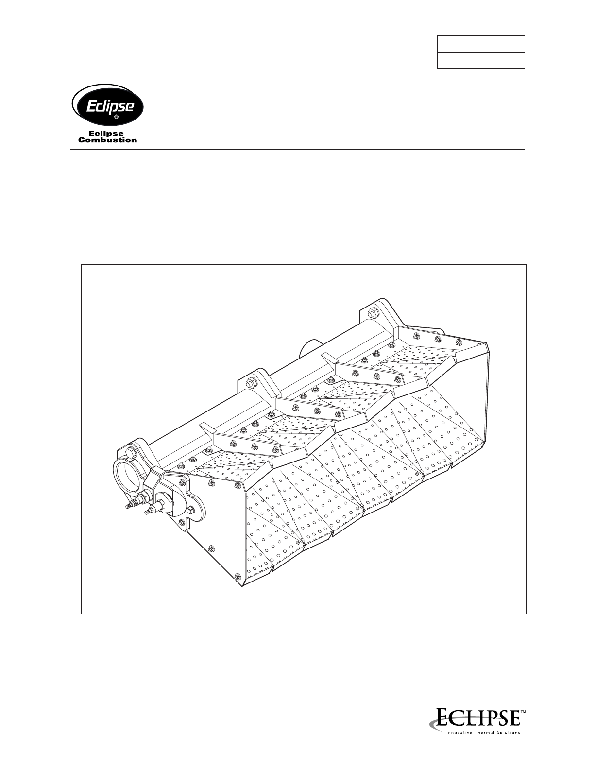
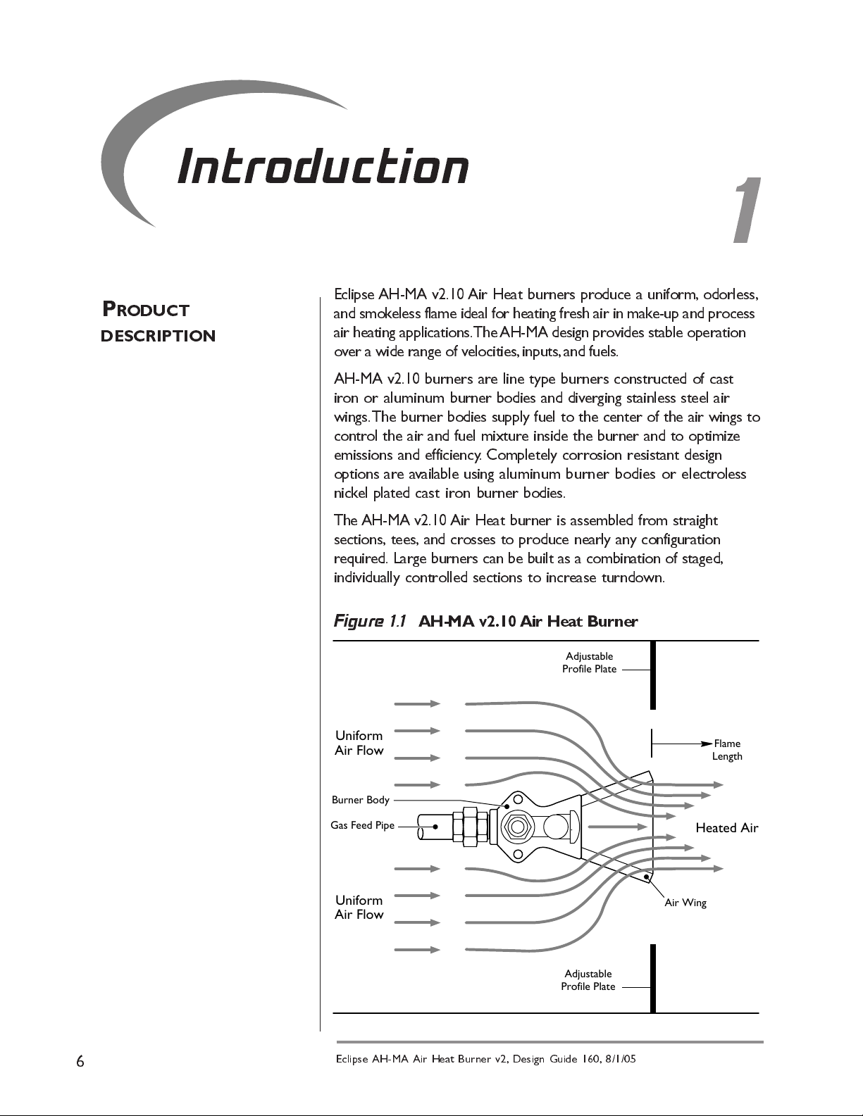
Eclipse AH-MA v2.10 Air Heat burners produce a uniform, odorless,
and smokeless flame ideal for heating fresh air in mak e-up and process
air heating applications. The AH-MA design provides stable operation
over a wide range of velocities, inputs, and fuels.
AH-MA v2.10 burners are line type burners constructed of cast
iron or aluminum burner bodies and diverging stainless steel air
wings. The burner bodies supply fuel to the center of the air wings to
control the air and fuel mixture inside the burner and to optimize
emissions and efficiency. Completely corrosion resistant design
options are a vailable using aluminum burner bodies or elec troless
nickel plated cast iron burner bodies.
The AH-MA v2.10 Air Heat burner is assembled from straight
sections, tees, and crosses to produce nearly any configuration
required. Large burners can be built as a combination of staged,
individually controlled sections to increase turndown.
Figure 1.1 AH-MA v2.10 Air Heat Burner
Adjustable
Profile Plate
Uniform
Air Flow
Burner Body
Gas Feed Pipe
Uniform
Air Flow
Adjustable
Profile Plate
Flame
Length
Heated Air
Air Wing
6
Eclipse AH-MA Air Heat Burner v2, Design Guide 160, 8/1/05
Page 7
Safety
I
NTRODUCTION
S
AFETY
2
In this section, you will find important notices about safe
operation of a burner system.
Danger:
The burners covered in this manual are designed
to mix fuel with air and burn the resulting
mixture. All fuel burn-ing devices are capable of
producing fires and explosions when improperly
applied, installed adjusted, controlled, or
maintained.
Do not bypass any safety feature.
You can cause fires and explosions.
Never try to light the burner if the burner shows
signs of damage or malfunctioning.
Warning:
The burner and duct sections are likely to have
HOT surfaces. Always wear protective clothing
when approaching the burner.
Note:
This manual gives information for the use of these burners
for their specific limited design purpose. Do not deviate from
any instructions limits in this manual without written advice
from Eclipse Combustion.
Note:
Read this entire manual before you attempt to start the
system. If you do not understand any part of the information
in this manual, then contact your Eclipse representative or
Eclipse Combustion before you continue .
Eclipse AH-MA Air Heat Burner v2, Design Guide 160, 8/1/05
7
Page 8
C
APABILITIES
O
PERA TOR TRAINING
R
EPLACEMENT PARTS
Adjustment, maintenance and troubleshooting of the
mechanical and the electrical parts of this system should be
done by qualified personnel with good mechanical aptitude
and experience with combustion equipment.
The best safety precaution is an alert and competent operator.
Thoroughly instruct new operators so they demonstrate an
adequate understanding of the equipment and its operation. Regular
retraining must be scheduled to maintain a high degree of
proficiency.
Order replacement parts from Eclipse only. Any customer
supplied valves or switches should carry UL, FM, CSA, CGA and/or
CE approval where applicable.
8
Eclipse AH-MA Air Heat Burner v2, Design Guide 160, 8/1/05
Page 9

D
ESIGN
System Design
Design structure
Designing a burner system is a straight-forward exercise of
combining modules that add up to a reliable and safe system.
The design process is divided into the following steps:
1.
Burner design
a.
calculating the maximum input requirements
b.
choosing design heat input at high fire
c.
determining the length of burner needed
d.
calculating the minimum input requirements
e.
layout of the burner sections
f.
sizing and layout of the gas manifold
g.
sizing the profile plates
h.
burner staging
2.
Control methodology
3.
Ignition system
4.
Flame monitoring system
5.
Gas valve train selection
3
Note:
Information in Data Sheet No. 160 is necessary to complete
some of the procedures.
Eclipse AH-MA Air Heat Burner v2, Design Guide 160, 8/1/05
9
Page 10

Step 1:
Burner design
Calculating the maximum input requirements
To calculate the total burner maximum input required, solve:
∆
Max. Input (Btu/hr) = 1.3 x SCFM x
Caution:
This is an approximation based on the gross heating value of the
fuel. For mo r e accurate heat balance calculations, refer to the
Eclipse Combustion Engineering Guide (EFE-825).
Choosing design heat input at high fire
See Data Sheet No. 160 for the following:
1) Use the Operating Range chart to determine the maximum and
minimum heat inputs per foot of burner based on the known air
pressure drop.
2) Use the Flame Length chart to check flame length v ersus available
distance downstream of the burner for uniform temperature
distribution.
Determining the length of burner needed
Burner length, feet =
max. heat input, total burner (Btu/hr)
heat input per foot (Btu/hr/ft)
T (max)
Note:
Round fractional lengths (in ft.) up to the next half-foot.
Calculating minimum input required
1)
Minimum Input (Btu/hr) = 1.3 x SCFM x T (min)
2)
Min. Heat Input per foot, Btu/hr/ft =
3) With the minimum heat input per foot, go to the Operating
Range chart in Data Sheet No. 160 and confirm that the burner
can operate at the input for the air pressure drop the burner will
see. If the minimum input required is too low, there are two
options to obtain this operating condition:
a. Use a staged burner control (see burner staging and contr o l
methods in this section).
b. Modulate the air flow to a lower pressure drop, thus lowering
the minimum input capability of the burner.
Example
60,000 SCFM air from 0°F to 80°F maximum; and, from 75°F to
80°F minimum. Air
0.7"w.c. at high fire. The fuel is natural gas.
: A make-up air heat burner will be used to heat
∆
P across the burner is designed to be
min. heat input, total burner, Btu/hr.
D
burner length, feet
10
1) Max. Input Required: Btu/hr = 1.3 X 60,000 X 80 = 6,240,000
Btu/hr.
Eclipse AH-MA Air Heat Burner v2, Design Guide 160, 8/1/05
Page 11

2) From the Operating Range chart in Data Sheet No. 160, the maximum
heat input at 0.7"w.c. air pressure drop is 800,000 Btu/hr/ft. The flame
length from the Flame Length chart in Data Sheet No. 160 is 30".
Burner length, feet =
6,240,000 Btu/hr
= 7.8 feet; round up to 8 feet.
800,000 Btu/hr/ft
3) Minimum: Btu/hr = 1.3 X 60,000 X 5 = 390,000 Btu/hr.
4) Minimum per foot =
390,000 Btu/hr
= 48,750 Btu/hr/ft.
8 ft.
5) From the Operating Range chart in Data Sheet No. 160, the
minimum input at 0.7 w .c. is 20,000 Btu/hr/ft. Ther efore, the
burner can operate over the desired input range.
Layout of the burner sections
Once the lineal feet of burner has been determined, use Figure 3.2
and the criteria below to define the burner geometry.
For optimum burner performance and a uniform temperature profile,
even gas and air flow throughout the burner is essential. The following
guidelines should be used to lay out a burner:
1) Every leg of a Tee or Cross section must be separated from another
Tee or Cross section by at least 150mm (6") of burner.
2) Include the proper number of gas feed inlet sections. Use Table 3.1
as a guide to the number and size of gas feed inlets required based
on the length of the burner .
Table 3.1 Gas Feed Inlet Capacities
Gas Inlet
Pipe Size
1-1/2"
1-1/2"
1-1/2"
1-1/2"
* Number of feet or 300mm sections
Directon
1"
2"
2"
2"
1"
2"
2"
2"
Side
Rear
Side
Rear
Rear
Side
Side
Rear
Side
Rear
Rear
Side
300mm straight section
300mm straight section, Cast Iron
300mm straight section
300mm straight section, Aluminum
300mm x 300mm cross section
300mm straight section
300mm straight section
300mm straight section, Cast Iron
300mm straight section
300mm straight section, Aluminum
300mm x 300mm cross section
300mm straight section
Section Type
Gas
Pressure
standard
standard
standard
standard
standard
standard
Low
Low
Low
Low
Low
Low
Max. Burner
Length Per
Inlet*
1
4
3
4
6
4
.5
2
1.5
2
6
2
Example: A six-foot burner for standard gas pressure will use 2"
N.P.T. rear inlets to supply gas. How man y gas inlets are required?
Solution:
Therefore,
Each 2" back inlet can supply 4 feet of burner.
6/4
= 1.5, or 2 inlets are required
3) Space gas inlets equally to assure uniform gas distribution.
Eclipse AH-MA Air Heat Burner v2, Design Guide 160, 8/1/05
11
Page 12

10.6"
1.6"
5.9"
11.8"
5.9"
150mm x 300mm Tee Section
7
(LBS.)
WEIGHT
102250-2
CAST IRON
LOW PRESSURE
BURNER BODIES
14
16
16
102238-2
102240-2
102239-2
19
30
30
102251-2
102255-2
102254-2
Cast Iron Burner Sections
10.6"
10.6"
10.6"
1.6"
1.6"
1.6"
5.9"
1.5" I.D.
11.8"
2.2"
11.8"
9.6"
9.6"
9.6"
ASSEMBLY NUMBERS
with Back Inlet
300mm Straight Section
300mm Straight Section
Burner Sections Assembly Numbers, Dimensions & Weights
10.6"
102250-1
RESISTANT
CORROSION
BURNER BODIES
102250
BODIES
BURNER
CAST IRON
DESCRIPTION
150mm Straight Section
102238-1
102240-1
102239-1
102251-1
102255-1
102254-1
102238
102240
102239
102251
102255
102254
300mm Straight Section
300mm Straight Section w/Back Inlet, BSP
300mm Straight Section w/Back Inlet, NPT
300mm x 150mm Tee Section
300mm x 300mm Cross Section, BSP
300mm x 300mm Cross Section, NPT
1.9"
5.9"
11.8"
5.9"
I.D.
2.0"
150mm Straight Section
300mm x 300mm Cross
Figure 3.1
1
2
Eclipse AH-MA Air Heat Burner v2, Design Guide 160, 8/1/05
Page 13

10.6"
1.6"
5.9"
11.8"
5.9"
150mm x 300mm Tee Section
3.5
(LBS.)
WEIGHT
7.0
8.0
8.0
9.0
14.0
14.0
Aluminum Burner Sections
10.6"
10.6"
1.6"
1.6"
5.9"
2.0" I.D.
11.8"
2.0"
11.8"
9.6"
9.6"
ALUMINUM
LOW PRESSURE
with Back Inlet
300mm Straight Section
300mm Straight Section
ASSEMBLY NUMBERS
ALUMINUM
Burner Sections Assembly Numbers, Dimensions & Weights
10.6"
BURNER
102250-4
102238-4
102240-4
102239-4
BURNER BODIES
102250-3
102238-3
102240-3
BODIES
DESCRIPTION
150mm Straight Section
102239-3
300mm Straight Section
300mm Straight Section w/Back Inlet, BSP
300mm Straight Section w/Back Inlet, NPT
1.9"
102251-4
102255-4
102254-4
102251-3
102255-3
102254-3
300mm x 150mm Tee Section
300mm x 300mm Cross Section, BSP
300mm x 300mm Cross Section, NPT
11.8"
Figure 3.1 (Continued)
10.6"
1.6"
5.9"
2.0"
5.9"
I.D.
9.6"
150mm Straight Section
Eclipse AH-MA Air Heat Burner v2, Design Guide 160, 8/1/05
300mm x 300mm Cross
1
3
Page 14

3.1"
5.2"
3.9"
Plug
Rod
Flame
Plug
Rod
Flame
Main Gas
Connection
Plug
Ignition
1/4" npt
Pilot Gas
Connection
Plug
Ignition
U.V. Scanner
Adaptor
U.V. Scanner
Main Gas
Connection
(shown with optional UV scanner, flame rod & spark plug installed)
with
Flame Rod
Flame Monitoring End
PA RT
with
Pilot End
Flame Rod
Accessories
with
Pilot End
U.V. Scanner
Ø0.5"
21509
13093
76506
13047-1
NUMBER
DESCRIPTION
Mtg. Brkt. for Hanger Rods
Ignition Plug
Flame Rod
Divider Plate for Staging
444444444 4 4 4 4 4 4
(LBS.)
WEIGHT
—
BC
—
DIMENSIONS
A
—
for Staging
Divider Plate
18767
202010
UV Scanner Adapter – 1/2" NPT
1" NPT
14mm
—
12659
202011
UV Scanner Adapter – 3/4" NPT
UV Scanner Adapter – 1" NPT
Pilot Gas Cock
1" BSP
1" NPT
14mm
14mm
1" BSP
1.5"NPT
1" BSP
14mm
1.5" BSP
1" NPT
14mm
1" NPT
Flame rod ordered with burner includes adapter to pilot or flame monitoring
endplate.
Adapter fits Eclipse straight, Eclipse 90 and Honeywell C7027A U.V. scanners.
Adapter fits Eclipse self-check and Honeywell C7035A U.V. scanners.
1" BSP
1" NPT
14mm
14mm
2" BSP
2" NPT
1" BSP
1" NPT
14mm
14mm
———
1" BSP
1" NPT
—
—
—
—
1" BSP
1" NPT
**
**
—
1-1/2" BSP
1-1/2" BSP
1-1/2" NPT
4
—
—
1-1/2" NPT
Figure 3.1 (Continued)
1
4
8.7"
2"
8.7"
C (pipe thread)
B (straight thread)
End Plate Assemblies End Plate Examples
102257-1
10010970-1
RESISTANT
END PLATES
CORROSION
3.9" 0.8"
Plain End Plate Assembly
1.3"
2.6"
3.9"
0.8"
A (pipe thread)
Pilot, Flame Monitoring and
Burner Feed End Plate Assemblies
Eclipse AH-MA Air Heat Burner v2, Design Guide 160, 8/1/05
ASSEMBLY NUMBERS
End Plate Assembly Numbers, Dimensions & Weights
CAST IRON
END PLATES*
DESCRIPTION
10010972-1
102257
10010970
10010972
Plain End Plate
Pilot End Plate, No Gas Feed
Pilot End Plate, 1" Gas Feed NPT
10010974-1
10010975-1
10010976-1
10010974
10010975
10010976
Pilot End Plate, 1" Gas Feed BSP
Pilot End Plate, 1.5" Gas Feed NPT
Pilot End Plate, 1.5" Gas Feed BSP
101237-1
10010977-1
10010978-1
10010979-1
10010977
10010978
10010979
Pilot End Plate, 2" Gas Feed NPT
Pilot End Plate, 2" Gas Feed BSP
Pilot End Plate, Angled Flame Monitor NPT
101238-1
10010980-1
101237
101238
10010980
Pilot End Plate, Angled Flame Monitor BSP
Flame Monitoring End Plate, BSP
Flame Monitoring End Plate, NPT
101233-1
101234-1
101235-1
101233
101234
101235
Burner Feed/Flame Monitoring End Plate, BSP
Burner Feed/Flame Monitoring End Plate, NPT
Burner Feed End Plate, BSP
101236-1
101236
Burner Feed End Plate, NPT
* Standard Cast Iron End Plates with powder coated surface finish are supplied on burners with aluminum gas manifolds.
** 14mm plug may be replaced by ignition plug for direct spark ignition of burners 450mm (18") or less.
Page 15

Sizing and layout of the gas manifold
Choose the gas manifold size to evenly supply gas to each of the
sections, using Table 3.3 and Figure 3.2.
Table 3.3
MAXIMUM MANIFOLD MAXIMUM MAIN GAS
GAS INPUT PIPE SIZE GAS INPUT PIPE SIZE
(MMBTU/HR.) (INCHES) (MMBTU/HR.) (INCHES)
Gas Pipe Sizing & Layout
1.4 1-1/2 0.3 1/2
2.5 2 0.6 3/4
5.2 2-1/2 1.1 1
8.0 3 3.2 1-1/2
14.0 4 6.6 2
45.0 6 13.0 2-1/2
80.0 8 20.0 3
Note:
Maximum inputs shown for natur al gas only. For propane,
multiply inputs by 1.5; for butane, multiply inputs by 1.7.
Figure 3.2 Gas Manifold Sizing & Lay o u t
Main
Gas
Pipe
Union
Gas Manifold
Feed Pipe
Pipe
Union
Burner
Burner Body
Pipe
Union
Pilot End Plate
Spark
Ignitor
Pilot
Gas
Flame
Rod
Example: A gas manifold is supplying gas to two 1-1/2" N.P.T. rear
inlets on a burner. Each of the rear inlets supplies a maximum of
2,000,000 Btu/hr.
Solution: The total fuel supplied is 2 x 2,000,000 = 4,000,000 Btu/hr.
Referring to Table 3.3, the choice for manifold size is 2-1/2"; the
choice for main gas pipe size is 2".
Eclipse AH-MA Air Heat Burner v2, Design Guide 160, 8/1/05
1
5
Plain
End Plate
Page 16

Profile plate sizing
Profile plates are required to ensure sufficient air pressure drop across
the burner . An example of pr ofile plate lay out is shown in Figure 3.4 on
the next page.
Caution:
It is essential that even air flow is delivered to the
burner to obtain optim um performance.
To calculate the profile gap sizes, you will need to know the following:
1) SCFM
= Total air flow around and through the burner in cubic feet
per minute.
2) Design pressure drop across the burner .
= Profile gap area required per flow from Figur e 3.3; see Table 3.4
3) G
p
for corrections at higher or low er burner air inlet temperature s.
Profile area, A
g
=
SCFM x G
p
1000
Where:
Ag
= Area in square inches of the gap between the profile plates and
the burner.
The areas on the sides of the burners should first be calculated based
on a fixed gap of 2". Then calculate the gap size required on the top
and bottom to obtain the required profile gap area.
Example: Size a profile plate for a seven-foot long AH-MA v2.00
burner. Air flow around and through the burner will be 60,000 SCFM.
The design pressure drop is 0.7"w.c.
Note:
Use a burner wing width of 8.9 for profile gap sizing on top and
bottom.
From Figure 3.3: G
=
g
60,000 x 48
1,000
A
= 48
p
= 2,880 sq. in.
Calculate gap sizes:
Side Area = 2 x 2" x 8.9" = 36 sq. in.
Area Top & Bottom = 2,880 36 = 2,844 sq. in.
Therefore, Top & Bottom Gap =
2,844 sq. in.
= 16.9 inches
(7 x 12) x 2 gaps
where 7 x 12 = burner length in inches
1
6
Eclipse AH-MA Air Heat Burner v2, Design Guide 160, 8/1/05
Page 17

Figure 3.3 Profile Gap Area vs. Air Pr essure Gap
110
100
90
80
70
60
50
(Sq. In. per 1000’s SCFM)
40
Gp, Profile Gap Area Required
30
20
0.1 0.2 0.3 0.4 0.5 0.6 0.7 0.8 0.9 1.0 1.1 1.2 1.3 1.4
Table 3.4
AIR T
EMP
. (°F) 0 30 70 150 200 250 300 350 400 450
Burner Air Inlet Temperature @ 70 F
Combustion Air Pressure Drop ("w.c.)
Profile Gap Area Inlet Air Temperature Correction
GP @ AIR T
EMP. =
G
P
FROM FIG
. 3.4 X C
ORRECTION FACTOR
Correction Factor 0.87 0.92 1.00 1.15 1.25 1.34 1.43 1.53 1.62 1.72
Figure 3.4
6" Min.
Duct
Height
(244mm)
6" Min.
Single Burner Profile Plates
9.6"
Duct Width
6" Min.
AH-MA Burner
Profile Plate
2"2"
Gap, As
Required
Gap, As
Required
Eclipse AH-MA Air Heat Burner v2, Design Guide 160, 8/1/05
1
7
Page 18

Figure 3.5 Two-Stage Burner Profile Plates
First
Stage
Burner
Profile
Plate
6" Min. 3" Min.
2"
2"
6" Min.
2"
Second
Stage
Burner
Profile
Plate
2"
XXXX
Note:
Make all profile gaps equal (shown as “X” above); profile
plate width between the burners should be at least 3".
Duct Wall
Steel channel of the correct width can be used as the center profile
plate. Install with the legs pointing toward the incoming air flow.
Air Flow Air Flow
Staged Burners
Duct Wall
6" Min.
1
8
Eclipse AH-MA Air Heat Burner v2, Design Guide 160, 8/1/05
Page 19

Note:
To compensate for changes in actual air flo w versus calculated,
provide adjustable profile plates so that f inal settings can be
made in the field. Figure 3.6 shows an example of an adjustable
profile plate design.
Figure 3.6 Adjustable Profile Plates
AH-MA
Burner
Adjustable
Profile Plate
Fixed
Profile Plate
Duct
Wall
Figure 3.7 Profile Plate Positioning
Profile
Plate
¼ to 1"
Caution:
Profiles plate should be positioned
upstream of the firing end of the
burner. If necessary, the plates can be
AH-MA
Burner
Profile
Plate
located up to 1" back from the firing
end, but under no circumstances should
they be in front of the burner.
Elongated Screw Slots
Front ViewSide View
Eclipse AH-MA Air Heat Burner v2, Design Guide 160, 8/1/05
1
9
Page 20

Step 2:
Control
Methodology
The simplest control method is fuel modulation at fixed air flow. If
required turndown is greater than the burners capabilities, there
are two options:
1.
Air Modulation
To lower the minimum input of the burner, the air flow can be
decreased as long as the pressure drop across the burner does not
go outside of the operating limits given in the Operating Ranges
chart in Data Sheet No. 160. The air flow can be changed with a
two-speed air handling system or a modulated system. As an
example, the air flow could be turned down from a pressure drop
of 1"w .c. to 0.25"w .c., giving a total air turndown of 2:1. This could
extend the minimum input level from 20,000 to 13,000 Btu/hr/ft.
Figure 3.8 Staged Burners
Stage 2
Main
Gas
Pipe
Union
Pipe
Union
Stage 1
Main
Gas
Pipe
Union
Pipe
Union
Staging
Divider Plate
Part No. 76506
Pipe
Union
Stage 1
Pilot Gas
2
0
Eclipse AH-MA Air Heat Burner v2, Design Guide 160, 8/1/05
Page 21

2.
Burner Fuel Staging
To further increase the burner turndown, AH-MA v2.10 burners
can be fuel staged. This can be done by installing two or more
separate burners in a duct, each with its own gas control valve, or
by dividing a single burner assembl y into separate zoned sections.
For example, to double the effectiv e turndown, two burner
sections may be staged as shown in Figure 3.8 on the pre vious
page. If more heat is required, stage 2 is lit by simply supplying gas
to it. It will pilot from the adjacent stage.
Warning:
Lockouts must be provided to shut off gas flow to
stage 2 unless flame is pro ven on stage 1.
A spacer (part #76506) must be installed between the burner
bodies to separate the different gas feed sections.
Note:
Ignition performance is enhanced if the gas inlet to stage 2 is as
close to the piloting section as possible.
Step 3:
Ignition System
A
H-MA v2.10 Air Heat burners have an integral spark-ignited gas
pilot for lighting the burner . The pilot fuel is fed into the pilot end
casting which is separate from the main fuel. A pilot adjusting valve
is required to adjust the pilot gas flow (Eclipse part number
12659 is recommended). The needed pilot capacity is 20,000 Btu/
hr, but the pilot will operate equally well at higher or lower inputs.
The pilot is shut off after successfully igniting the main burner to
protect the ignitor .
Local safety and insurance requirements demand that you limit the
maximum time that a burner takes to ignite. These time limits vary
from country to country. For the USA, the time limit is 15 seconds;
for Europe, it is typically 3 seconds. Local requirements may
require shorter time limits. Verify local regulation and insurance
requirements with the authority having jurisdiction.
The time that a burner takes to ignite depends on:
the distance between the gas shut-off valve and the burner
the air pressure drop across the burner
the gas flow at start conditions.
Eclipse AH-MA Air Heat Burner v2, Design Guide 160, 8/1/05
2
1
Page 22

Step 4:
system
Flame monitoring
90° U.V. scanner
flame rod
A
flame monitoring system consists of two main parts:
a flame sensor
a flame safeguard.
Flame Sensor
There are two types that you can use for an AH-MA v2.10 Air
Heat burner:
U.V. scanner
flame rod.
You can find information on U.V. scanners in:
Instruction Manual No. 852; 90° U.V. scanner
Instruction Manual No. 854; straight U.V. scanner
Instruction Manual No. 855; solid state U.V./IR scanner
Instruction Manual No. 856; self-check U.V. scanner.
You can find information on flame rods in:
Bulletin/Info Guide No. 832.
Flame Monitoring Control
The Flame Monitoring Control processes the signal from the flame
rod or U.V. scanner and controls both the start-up sequence and
the main gas shut-off valve sequence..
For flame safeguard selection there are two options for staged
burners depending on the application requirements:
flame safeguard for each burner: if one burner goes down, only
that burner will be shut off.
multiple burner flame safeguard: if one burner goes down, all
burners will be shut off.
Eclipse Combustion recommends the use of flame monitoring
control systems which maintain a spark for the entire trial for
ignition time when using U.V. scanners. Some of these flame
monitoring models are:
Veri-Flame series; see Bulletin/Instruction Manual No. 818
Bi-Flame series; see Bulletin/Instruction Manual No . 826
Multi-Flame series; see Bulletin/Instruction Manual No. 820.
Burners over 5 lineal feet include flame supervision at the far end.
If pilot ignition is being used, two flame supervision units are
required; one for the pilot and one for the far end. Per NFPA 86,
if using direct spark on the main flame, only flame supervision at
the far end is required providing ignition can be accomplished
within 15 seconds.
22
Eclipse AH-MA Air Heat Burner v2, Design Guide 160, 8/1/05
Page 23

Step 5:
Gas Valve Train
Selection
(from shut-off
valve train)
Main
Gas
Pilot
Gas
Main Gas
Control
Valve
Manual
Butterfly
Valve
Pilot
Shut-Off
Valve
Figures 3.9 and 3.10 illustrate gas valve trains for single and staged
burner systems respectively.
The typical main gas valve train for a staged burner has the same valve
layout as a single burner except each burner has an individual sole-
noid valve to independently shut down each section. A common gas
shut-off valve train can be used.
Figure 3.9 Single-Staged Burner Valve L ayout
Pipe
Union
Flexible
Solenoid
Valve
Nipple
Pipe
Union
Adjustable
Gas Cock
Adjustable
Orifice Valve
& Gas Cock
Flexible
Nipple
Duct Wall
OR
Main Burner
Shut-Off Valve
Pilot
Pressure
Regulator
Eclipse AH-MA Air Heat Burner v2, Design Guide 160, 8/1/05
2
3
Page 24

Main
Gas
(from shut-off
valve train)
Pilot
Gas
Solenoid
Valve
Solenoid
Valve
Main Gas
Control
Valve
Main Gas
Control
Valve
Pilot
Shut-Off
Valve
Figure 3.10 Staged Burner Valve Layout
Burner 1
Shut-Off Valve
Manual
Butterfly
Valve
Flexible
Nipple
Duct Wall
Pipe
Flexible
Burner 2
Shut-Off Valve
Manual
Butterfly
Valve
Solenoid
Valve
Pilot
Pressure
Regulator
Nipple
Pipe
Union
Adjustable
Gas Cock
OR
Adjustable
Orifice Valve
& Gas Cock
Flexible
Nipple
Note:
A single pilot fuel feed can be used when the stag ed burners are
piloted by the adjacent burners.
Union
Pipe
Union
Consult Eclipse
Eclipse can help you design and obtain a main gas shut-off valve train that
complies with the current safety standards.
The shut-off valve train must comply with local safety standards set by
authorities that hav e jurisdiction.
For details, please contact your local Eclipse representative or Eclipse
Combustion.
Note:
Eclipse supports NFP A r egulations (two shut-off valves) as a
minimum standard for main gas safety shut-off valves.
2
4
Eclipse AH-MA Air Heat Burner v2, Design Guide 160, 8/1/05
Page 25

C
ONVERSION
Appendix
Metric to English.
FA CTORS
F
ROM
T
O
M
ULTIPLY BY
cubic meter (m3) cubic foot (ft3) 35.31
3
cubic meter/hour (m
/h) cubic foot/hour (cfh) 35.31
degrees Celsius (°C) degrees Fahrenheit (°F) (°C x 1.8 ) + 32
kilogram (kg) pound (lb) 2.205
kilowatt (kW) Btu/hr 3414
meter (m) foot (ft) 3.28
millibar (mbar) inches water column ("wc) 0.401
millibar (mbar) pounds/sq in (psi) 14.5 x 10
millimeter (mm) inch (in) 3.94 x 10
Metric to Metric.
F
ROM
T
O
M
ULTIPLY BY
kiloPascals (kPa) millibar (mbar) 10
meter (m) millimeter (mm) 1000
millibar (mbar) kiloPascals (kPa) 0.1
millimeter (mm) meter (m) 0.001
-3
-2
English to Metric.
F
ROM
T
O
M
ULTIPLY BY
Btu/hr kilowatt (kW) 0.293 x 10
cubic foot (ft3) cubic meter (m3) 2.832 x 10
cubic foot/hour (cfh) cubic meter/hour (m3/h) 2.832 x 10
degrees Fahrenheit (°F) degrees Celsius (°C) (°F 32) ÷ 1 .8
foot (ft) meter (m) 0.3048
inches (in) millimeter (mm) 25.4
inches water column ("wc) millibar (mbar) 2.49
pound (lb) kilogram (kg) 0.454
pounds/sq in (psi) millibar (mbar) 68.95
Eclipse AH-MA Air Heat Burner v2, Design Guide 160, 8/1/05
-3
-2
-2
2
5
Page 26

Design Guide 160 8/1/05
Litho in U.SA.
 Loading...