

Page 1
Instruction Manual 819
2/11/2011
Eclipse Veri-Flame Tester
and Trainer
Model 5602
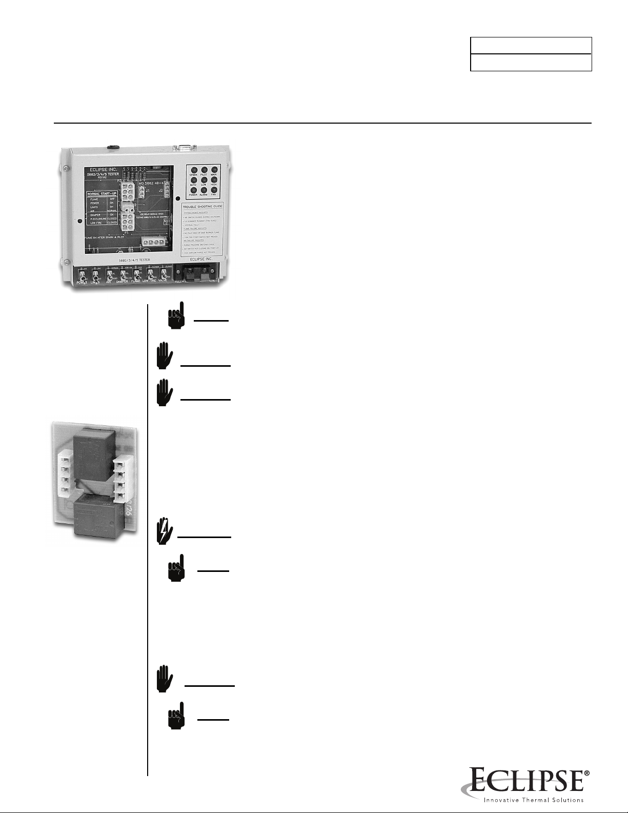
The Model 5602 Tester (pn 49602) provides a convenient means for testing
Veri-Flame controllers and sensors. It also is a good tool for learning about
the sequences and safety features of all the Veri-Flame models. Features
include:
• 7 Toggle switches for simulating inputs
• 9 Lights for controller output status
• 2 Quick-connect terminals for external flame sensor
• Built in flame simulators
• Tests 120V or 240V supply models
NOTE: The tester is supplied with a standard North American 120VAC plug. The
plug can be cut off and the remaining powercord can be attached to an
appropriate plug or terminal for 240VAC supply.
Relay Board
Model 5603-40-4
Part No. 49240-2
CAUTION: The tester must be supplied with the voltage level that matches the Veri-
Flame model being tested.
CAUTION: Before beginning the test procedures, read the Eclipse Combustion
Instruction Manual 818 and become thoroughly familiar with the controller
model that you are testing.
Mounting Controllers to the 5602 Series Tester
Check the controller model number and DIP-Switch settings to be sure that the
recycling, pilot mode, trial-for-ignition, purge time, and post purge settings are
correct for your application. Be sure the modulation relay board is installed for
modulation model controllers (560x-4x) and unplugged for non-modulating
controllers. Before plugging in the power cord of the tester, seat the controller
firmly in place over the opening on the face of the 5602 Series Tester.
WARNING: Risk of electrical shock. High voltage is exposed when tester is plugged in
but the Veri-Flame control is removed.
NOTE: Intermittent pilot operation (DIP-Switch 2 on) means the pilot stays on during
the burner run period. Interrupted pilot (DIP-Switch 2 off) means the pilot will
turn off after the main flame has established.
Initial Switch Settings:
POWER: OFF
LIMITS: OFF
AIR: NORMAL
DAMPER: VER-OK
FLAME: EXT
LOW FIRE: CLOSED
VALVE: CLOSED
CAUTION: Remove any external flame sensors from the connector block S1 and S2
when using the internal flame simulator.
NOTE:
The internal flame simulators are factory preset. Some adjustment of the UV
signal is possible by turning U.V. SENS. adjustment (on the rear).
Page 2
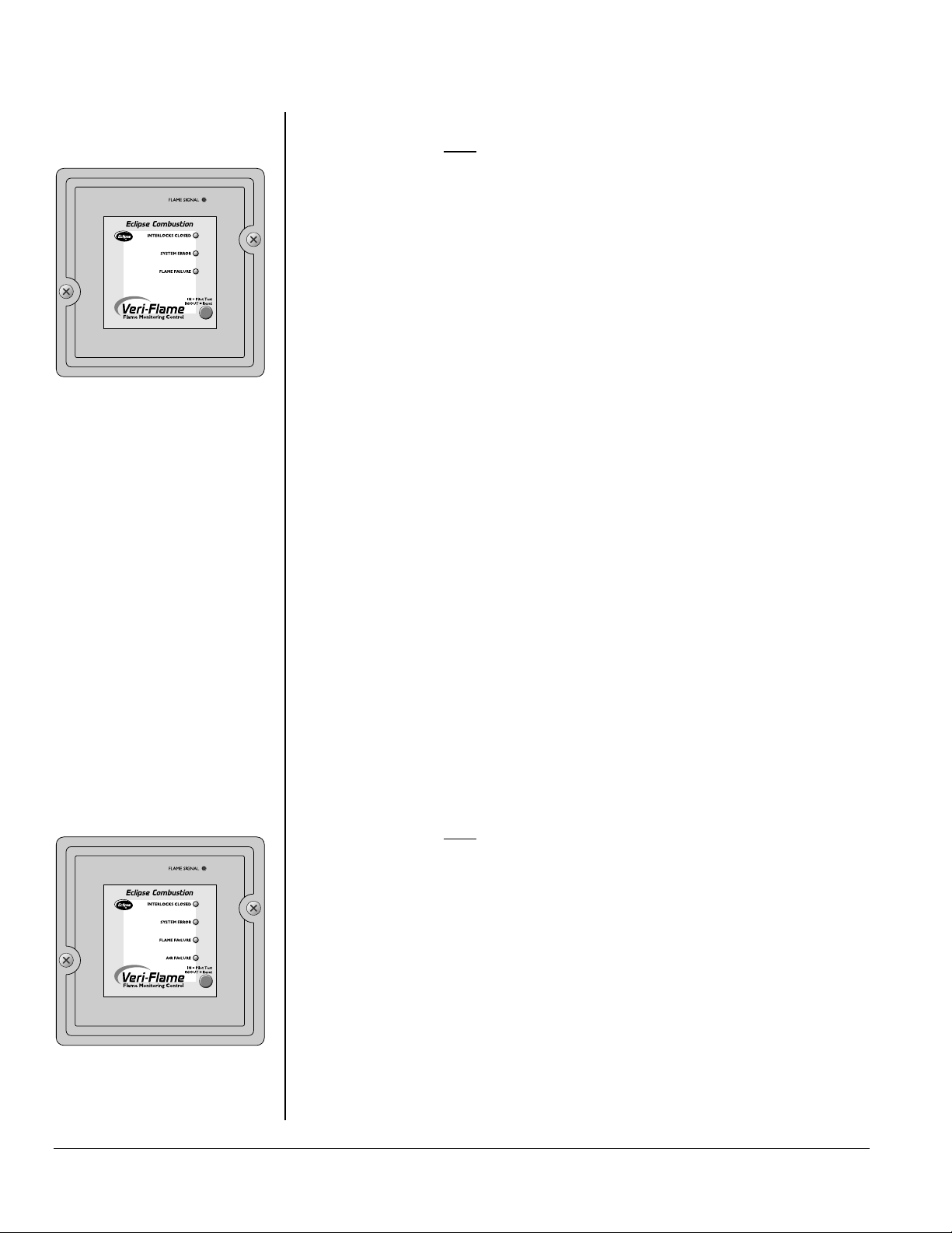
No Purge Model
Veri-Flame No-Purge Models 5602-3x and 5605-3x
Do NOT use the modulation relay board for these controllers.
Test Procedure - set initial switch settings
1) Turn on the POWER switch, the POWER light will come on.
2) Turn on the LIMITS switch. The green “INTERLOCKS CLOSED” light on the
controller will come on. Then the SPARK and PILOT lights on the tester will
come on.
3) Set the FLAME switch to the appropriate position for the flame sensor type of
the model under test: FR (down) for flame rods, UV/IR (up) for ultraviolet
scanners.
4) Observe that the red light inside the FLAME SIGNAL test jack comes on. At
the end of TFI (trial for ignition) time, the SPARK light will go off. Then about 5
seconds after the TFI ends, the MAIN light will come on. If interrupted pilot is
selected (DIP-Switch 2 is off), the PILOT light will go off after about 10
seconds.
5) Set the FLAME switch to EXT.
a) For non-recycling selection (DIP-Switch 1 is off), the red “FLAME
FAILURE” light on the controller will come on within 4 seconds. The
ALARM light on the tester will also come on.
b) For recycling selection (DIP-Switch 1 is on) and the flame indicator has
been on for more than 35 seconds, the unit will turn off the MAIN (and
PILOT if on) and recycle to the beginning self-check sequence. Then the
SPARK and PILOT will come on as in step 2 above. Leave the FLAME
switch at EXT. The red “FLAME FAILURE” light on the controller will come
on after the trial for ignition. The ALARM light on the tester will also come
on.
6) With the control in the ALARM condition, set the DAMPER switch to FAIL
(center position). Reset the controller by pressing the pushbutton once to the
in position and pressing it again to bring it back out.
7) Observe that the “SYSTEM ERROR” light flashes for a couple seconds and
then comes on steady. Also the tester ALARM light comes on. Return the
DAMPER switch to VER-OK.
8) Place the LIMITS switch to OFF and reset the controller. Turn the FLAME
switch to the appropriate position for the flame sensor type. Observe the red
light inside the FLAME SIGNAL test jack. The “SYSTEM ERROR” light will
start flashing. Wait about 25 seconds and the ALARM light will come on.
Veri-Flame Purge Models 5602-2x and 5605-2x
Do NOT use the modulation relay board for these controllers.
Test Procedure - set initial switch settings
1) Turn on the POWER switch, the POWER light will come on.
2) Turn on the LIMITS switch. The green “INTERLOCKS CLOSED” light on the
controller will come on. In less than 5 seconds, the FAN light on the tester will
come on.
3) The unit will stay in this sequence for the selected purge time, then the SPARK
and PILOT lights on the tester will come on.
4) Set the FLAME switch to the appropriate position for the flame sensor type of
the model under test: FR (down) for flame rods, UV/IR (up) for ultraviolet
scanners.
Purge Model
2 Eclipse Model 5602 Tester, Instruction Manual 819 2/11/2011
Page 3

5) Observe that the red light inside the FLAME SIGNAL test jack comes on. At
the end of TFI (trial for ignition) time, the SPARK light will go off. Then about 5
seconds after the TFI ends, the MAIN light will come on. If interrupted pilot is
selected (DIP-Switch 2 is off), the PILOT light will go off after about 10
seconds.
6) Set the FLAME switch to EXT.
a) For non-recycling selection (DIP-Switch 1 is off), the red “FLAME
FAILURE” light on the controller will come on within 4 seconds. The
ALARM light on the tester will also come on.
b) For recycling selection (DIP-Switch 1 is on) and the flame indicator has
been on for more than 35 seconds, the unit will turn off the MAIN (and
PILOT if on). Then if post purge is selected (DIP-Switch 8 is on) it will delay
15 seconds before it recycles to the beginning self-check sequence and
continues as in step 2 above. Leave the FLAME switch at EXT. The red
“FLAME FAILURE” light on the controller will come on after the trial for
ignition. The ALARM light on the tester will also come on.
7) With the control in the ALARM condition, set the DAMPER switch to FAIL
(center position). Reset the controller by pressing the pushbutton once to the
in position and pressing it again to bring it back out.
8) Observe that the “SYSTEM ERROR” light flashes for a couple seconds and
then comes on steady. Also the tester ALARM and FAN lights will come on.
Return the DAMPER switch to VER-OK.
9) Set the AIR switch to FAIL (center position). Reset the controller. The FAN light
will come on and about 10 seconds later the “AIR FAILURE” light on the
controller and the ALARM light on the tester will both come on.
10) Set the AIR switch to SHORT (down position). Reset the controller and
observe that the “SYSTEM ERROR” light flashes for about 15 seconds. Then
the “SYSTEM ERROR” light comes on steadily and the ALARM light on the
tester comes on. Return the AIR switch to the NORMAL position.
11) Place the LIMITS switch to OFF and reset the controller. Turn the FLAME
switch to the appropriate position for the flame sensor type. Observe the red
light inside the FLAME SIGNAL test jack. The “SYSTEM ERROR” light will
start flashing. Then the FAN light will come on. Wait about 25 seconds and the
ALARM light will come on.
Veri-Flame Modulation Models 5602-4x
Plug the modulation relay board into the tester base for these
controllers. The connector closest to the edge of the pc-board will
mate to J2 on the tester and should be oriented to the right. Plug
the board in with the pc-board down and the relays up.
Test Procedure - set initial switch settings
1) Turn on the POWER switch, the POWER light on the tester and the “LOW
FIRE” light on the controller will come on.
2) Turn on the LIMITS switch. The green “INTERLOCKS CLOSED” light on the
controller will come on. In less than 5 seconds, the tester FAN and HIGH lights
and the controller’s “HIGH FIRE” light will come on.
3) The unit will stay in this sequence for the selected purge time. Then the tester
HIGH and the controller’s “HIGH FIRE” lights go off and the LOW and “LOW
FIRE” lights will come on.
4) After the selected purge time, the SPARK and PILOT lights on the tester will
come on.
5) Set the FLAME switch to the appropriate position for the flame sensor type of
the model under test: FR (down) for flame rods, UV/IR (up) for ultraviolet
scanners.
3Eclipse Model 5602 Tester, Instruction Manual 819 2/11/2011
Page 4

Modulation Model
6) Observe that the red light inside the FLAME SIGNAL test jack comes on. At
the end of TFI (trial for ignition) time, the SPARK light will go off. Then about 5
seconds after the TFI ends, the MAIN light will come on. If interrupted pilot is
selected (DIP-Switch 2 is off), the PILOT light will go off after about 10
seconds. Then after another 10 seconds, the LOW and “LOW FIRE” lights go
off and the AUTO lights come on.
7) Set the FLAME switch to EXT.
a) For non-recycling selection (DIP-Switch 1 is off), the red “FLAME FAILURE”
light on the controller will come on within 4 seconds. The ALARM light on
the tester will also come on.
b) For recycling selection (DIP-Switch 1 is on) and the flame indicator has
been on for more than 35 seconds, the unit will turn off the MAIN (and
PILOT if on) and will turn off the AUTO lights and turn on the LOW and
“LOW FIRE” lights. Then if post purge is selected (DIP-Switch 8 is on) it
will delay 15 seconds before it recycles to the beginning self-check
sequence and continues as in step 2 above. Leave the FLAME switch at
EXT. The red “FLAME FAILURE” light on the controller will come on after
the trial for ignition. The ALARM light on the tester will also come on.
8) With the control in the ALARM condition, set the DAMPER switch to FAIL
(center position). Reset the controller by pressing the pushbutton once to the
in position and pressing it again to bring it back out.
9) The HIGH and “HIGH FIRE” lights will come on for the selected purge time. At
the end of the high purge time the “SYSTEM ERROR” and “LOW FIRE” lights
come on. Also the tester’s LOW, ALARM, and FAN lights will come on. Return
the DAMPER switch to VER-OK.
10) Set the LOW FIRE switch to OPEN. Reset the controller. The controller will
sequence as in steps 2 and 3 above. At the end of the low purge time, the
“SYSTEM ERROR” light and the ALARM light come on. Return the LOW FIRE
switch to the CLOSED position.
11) Set the AIR switch to FAIL (center position). Reset the controller. The FAN light
will come on and about 10 seconds later the “AIR FAILURE” light on the
controller and the ALARM light on the tester will both come on.
12) Set the AIR switch to SHORT (down position). Reset the controller and
observe that the “SYSTEM ERROR” light flashes for about 15 seconds. Then
the “SYSTEM ERROR” light comes on steadily and the ALARM light on the
tester comes on. Return the AIR switch to the NORMAL position.
13) Place the LIMITS switch to OFF and reset the controller. Turn the FLAME
switch to the appropriate position for the flame sensor type. Observe the red
light inside the FLAME SIGNAL test jack. The “SYSTEM ERROR” light will
start flashing. Then the FAN light will come on. Wait about 25 seconds and the
ALARM light will come on.
Instruction Manual 819 2/11/2011
Testing External Flame Sensors
Any Eclipse flame sensor can be tested if the appropriate model Veri-Flame is
installed in the tester. Self-check scanners will require a separate 120VAC
supply connection to power its internal electronics and shutter. Connect the
signal wires to the S1 and S2 connector block. Place the FLAME switch to the
EXT position, and turn the POWER switch ON. Point a scanner towards a
flame or place a flame rod in contact with a flame. The flame must also contact
with a ground area at least 4 times greater than the flame rod for a good signal.
Either observe that the red light inside the FLAME SIGNAL test jack comes on
or use a DC voltmeter to measure the flame signal strength from the test jack
to S2.
 Loading...