

Page 1

V-Series Panels | User Guide
Eclipse® V-Series
Panels
A guide to the set-up
and functions of
V-series panels.
Part Number:399G206 Rev A
Date: 10 April, 2017
User
Guide
Page 2

V-Series Panels | User Guide (draft, not yet released)
Page 2
Document Reference
V-Series Panels User Guide
Part Number: 399G206 Revision: A
Legal Disclaimers
Copyright © 2017 HME Clear-Com Ltd.
All rights reserved.
Clear-Com and the Clear-Com logo are trademarks or registered trademarks of
HM Electronics, Inc.
The software described in this document is furnished under a license
agreement and may be used only in accordance with the terms of the
agreement.
The product described in this document is distributed under licenses restricting
its use, copying, distribution, and decompilation/reverse engineering. No part
of this document may be reproduced in any form by any means without prior
written authorization of Clear-Com, an HME Company.
Clear-Com Offices are located in California, USA; Cambridge, UK; Dubai, UAE;
Montreal, Canada; and Beijing, China. Specific addresses and contact
information can be found on Clear-Com’s corporate website:
www.clearcom.com
Clear-Com Contacts
Americas and Asia-Pacific Headquarters
California, United States
Tel: +1 510 337 6600
Email: CustomerServicesUS@clearcom.com
Europe, Middle East, and Africa Headquarters
Cambridge, United Kingdom
Tel: +44 1223 815000
Email: CustomerServicesEMEA@clearcom.com
China Office
Beijing Representative Office
Beijing, P.R.China
Tel: +8610 65811360/65815577
Page 3

V-Series Panels | User Guide (draft, not yet released)
Page 3
Table of Contents
1 Important Safety Instructions ........................................................ 8
Safety symbols ................................................................................... 9
Mains power cord ................................................................................ 9
2 Introduction ................................................................................. 10
2.1 V-Series Panels covered by this guide ........................................... 11
2.2 Further information .................................................................... 11
3 Overview ...................................................................................... 12
3.1 Headset connector options .......................................................... 12
3.2 Expansion panel options ............................................................. 12
3.3 Front panel lights and controls ..................................................... 13
3.3.1 V12LD ................................................................................ 13
3.3.2 V12PD ................................................................................ 13
3.3.3 V12RD ................................................................................ 14
3.3.4 V24LD ................................................................................ 14
3.3.5 V24PD ................................................................................ 14
3.3.6 V24RD ................................................................................ 15
3.3.7 V32LD ................................................................................ 15
3.3.8 V12LDE ............................................................................... 16
3.3.9 V12PDE .............................................................................. 16
3.3.10 V1RDE ............................................................................. 17
3.3.11 V16LDE ............................................................................ 17
3.3.12 V12LDD ........................................................................... 18
3.3.13 V12PDD ........................................................................... 19
3.3.14 V12RDD ........................................................................... 20
3.4 Key display window .................................................................... 20
3.4.1 Navigating the key display window .......................................... 21
3.4.2 Key display window controls .................................................. 22
3.4.3 Navigating the Reply key display window ................................. 23
3.5 Supported fonts in V-Series panels ............................................... 24
3.6 What’s new in Eclipse-HX v. 9.0 ................................................... 25
4 Installing V-Series panels ............................................................ 26
4.1 Placing panels ........................................................................... 26
4.1.1 Placing rack mounted panels .................................................. 26
4.1.2 Placing desktop panels .......................................................... 26
4.1.3 Placing expansion panels ....................................................... 29
4.2 Wiring V-Series panels ................................................................ 31
4.2.1 V-Series main panel rear connectors (no AES-3 or T-Adapter) .... 32
4.2.2 V-Series main panel rear connectors (AES-3) ........................... 32
4.2.3 V-Series main panel rear connectors (T-Adapter) (Now obsolete) 32
Page 4

V-Series Panels | User Guide (draft, not yet released)
Page 4
4.2.4 V Series expansion panel rear connectors ................................ 33
4.2.5 V-Series desktop panel rear connectors (no AES-3 or T-Adapter) 33
4.2.6 V-Series desktop panel rear connectors (AES-3) ....................... 34
4.2.7 V Series desktop panel rear connectors (T-Adapter) (Now obsolete)
34
4.2.8 Mains power cord ................................................................. 35
4.2.9 Power connector wiring ......................................................... 35
4.2.10 Analog matrix to panel wiring .............................................. 36
4.2.11 Matrix panel GPIO connector wiring ...................................... 37
4.2.12 Programmable Relay contacts .............................................. 38
4.2.13 Opto-isolated inputs ........................................................... 39
4.2.14 Auxiliary audio connector .................................................... 40
4.2.15 AES-3 option to AES-6 interface card .................................... 41
4.2.16 T-Adapter option to DIG-2/DIF-102 interface ......................... 43
4.2.17 LAN connector ................................................................... 44
4.2.18 Expansion panel output ...................................................... 44
4.3 IP connection to matrix ............................................................... 45
4.3.1 Adding one extra IP channel .................................................. 46
4.3.2 Adding two extra IP channels ................................................. 48
4.3.3 Binaural audio ...................................................................... 52
4.3.4 Advanced multi IP channel configurations ................................ 52
4.4 Front panel connectors ............................................................... 52
4.4.1 Microphone connector ........................................................... 53
4.4.2 Headset connectors .............................................................. 53
4.5 Mains AC Power ......................................................................... 55
4.6 Panel parameters in ECS / EHX .................................................... 55
4.6.1 Headset sidetone .................................................................. 55
4.6.2 Headset autodetect .............................................................. 55
4.6.3 Panel microphone gain .......................................................... 56
4.6.4 Speaker dim ........................................................................ 57
4.6.5 Page Override ...................................................................... 57
4.7 Panel-to-matrix card baud rate .................................................... 57
5 Using the Front Panel Controls ..................................................... 58
5.1 Mic On ..................................................................................... 58
5.2 Shift Page ................................................................................. 58
5.2.1 Selectable Shift Pages ........................................................... 58
5.2.2 Cyclic Shift Pages ................................................................. 59
5.3 Headset Select .......................................................................... 59
5.4 Menu ....................................................................................... 59
5.5 LS Main levels (volume) control ................................................... 60
5.6 Auxiliary levels (volume) control .................................................. 60
5.7 Listen Again .............................................................................. 60
5.8 Up / Down buttons on lever key and pushbutton panels .................. 60
5.9 Alternative text key .................................................................... 61
Page 5

V-Series Panels | User Guide (draft, not yet released)
Page 5
5.10 Rotary control on rotary panels ................................................. 62
5.11 Dial pad (2RU and desktop panels) ............................................ 62
5.12 Push-To-Talk (PTT) operation ................................................... 62
5.13 Status LEDs (Tallies) ............................................................... 63
5.14 Communication errors ............................................................. 64
5.15 Lever key panels ..................................................................... 64
5.15.1 Reply key general purpose input (GPI) functionality on lever key
panels 64
5.15.2 V32LD function keys .......................................................... 64
5.15.3 Change function key options on a V32LD panel ...................... 66
5.15.4 Using a Scrolling Assignment function key on a V32LD panel ... 67
5.16 Pushbutton panels ................................................................... 68
5.16.1 Pushbutton Reply key GPI operation ..................................... 68
5.17 Rotary panels ......................................................................... 68
5.17.1 Using rotary panel keys ...................................................... 69
5.17.2 Rotary panel Reply key ....................................................... 69
5.17.3 Assignment Panel (AP) mode and the INTERCOM key ............. 70
5.17.4 Rotary panel interruptible foldback (IFB) operation ................. 70
5.17.5 Rotary panel Forced Listen .................................................. 71
5.17.6 Rotary panel Reply key GPI operation ................................... 71
6 Using the Menu System ................................................................ 73
6.1 Navigating the menu system ....................................................... 73
6.2 Fast Key Assign ......................................................................... 74
6.2.1 The Dial code ....................................................................... 75
6.2.2 Dial code validation .............................................................. 75
6.3 Scrolling assignment .................................................................. 77
6.4 Top level menu .......................................................................... 77
6.5 SYS INFO (System Information) menu .......................................... 79
6.5.1 VIEW KEYS menu ................................................................. 80
6.5.2 PARTY LINE menu ................................................................ 82
6.5.3 FIXED GRP menu ................................................................. 84
6.5.4 NEAR PNLS menu ................................................................. 85
6.5.5 MONITORS Menu .................................................................. 86
6.5.6 FL SOURCE Menu ................................................................. 87
6.5.7 FL DEST menu ..................................................................... 88
6.6 LOCAL PREF (Local Preferences) menu .......................................... 89
6.6.1 TIMEOUTS menu .................................................................. 91
6.6.2 LEVEL ADJ (Level Adjust) Menu .............................................. 93
6.6.3 BRIGHTNESS menu .............................................................. 94
6.6.4 MESSAGE menu ................................................................... 95
6.6.5 RESET XPTS (Reset Crosspoints) menu .................................... 97
6.7 SYS CONFIG (System Configuration) menu .................................... 97
6.7.1 PARTY LINE configuration menu ............................................. 99
6.7.2 FIXED GRP configuration menu ............................................. 101
Page 6

V-Series Panels | User Guide (draft, not yet released)
Page 6
6.7.3 LOCAL PNL (Local Panel) configuration menu .......................... 103
6.7.4 LOCAL KEYS configuration menu .......................................... 104
6.7.5 ATTRIBUTES menu ............................................................. 107
6.7.6 REMOTE PNL menu ............................................................. 107
6.7.7 FL CONFIG (Forced Listen configuration) menu ....................... 110
6.7.8 INPUT LVLS (Input Levels) configuration menu ....................... 112
6.7.9 OUTPUT LVL (Output Levels) configuration menu .................... 116
6.8 DIAGNOSTIC menu .................................................................. 118
6.8.2 SYSTEM DATA menu ........................................................... 121
6.8.3 UPGRADE menu ................................................................. 122
6.9 CALL menu ............................................................................. 123
6.10 DIAL menu ........................................................................... 126
6.11 LOCAL EXCL (Local Exclusive) menu ........................................ 128
6.12 LOCAL PAGE (Local Page override) menu .................................. 128
6.13 ASSNMT PNL (Assignment Panel) menu .................................... 129
6.13.1 Assigning interruptible foldback (IFB) sources to an IFB
destination ................................................................................... 131
6.13.2 Assigning partyline members ............................................. 133
6.13.3 Assigning Fixed Group members ........................................ 133
6.14 SUPERVISE menu .................................................................. 134
6.15 SHIFT menu ......................................................................... 139
6.16 Menu map ............................................................................ 141
6.17 Accessing the IP configuration menus ...................................... 142
6.18 IP SETUP menu ..................................................................... 142
6.18.1 CONNECT menu .............................................................. 143
6.18.2 USER ID menu ................................................................ 146
6.18.3 PASSWORD menu ............................................................ 147
6.18.4 CNTL DELAY (Control Delay) menu ..................................... 148
6.19 NET SETUP menu .................................................................. 150
6.19.1 IP ADDRESS menu ........................................................... 152
6.19.2 IP GATEWAY menu .......................................................... 153
6.19.3 DNS SERVER menu .......................................................... 154
6.19.4 LOGIN IP menu ............................................................... 155
6.19.5 LOGIN PORT menu .......................................................... 156
6.19.6 DHCP menu .................................................................... 157
6.19.7 SUBNETMASK (Subnet Mask) menu .................................... 157
6.19.8 CON TYPE (Connection Type) menu .................................... 158
6.19.9 DNS/IP .......................................................................... 160
6.20 CONFIRM CLEAR menu .......................................................... 160
6.21 IP menu map ........................................................................ 161
7 Maintaining V-Series panels ....................................................... 162
7.1 Accessing the Local Maintenance Menu (LMM) .............................. 162
7.2 Navigating the LLM menu .......................................................... 163
Page 7

V-Series Panels | User Guide (draft, not yet released)
Page 7
7.2.1 Use of displays ................................................................... 163
7.3 Commands ............................................................................. 164
7.3.1 Version ............................................................................. 165
7.3.2 xpoint ............................................................................... 165
7.3.3 Level ................................................................................ 167
7.3.4 Control ............................................................................. 167
7.3.5 Limit ................................................................................. 169
7.3.6 Filter ................................................................................ 170
7.3.7 la (Listen Again) ................................................................. 171
7.3.8 Mixer ................................................................................ 172
7.3.9 Setup ............................................................................... 173
7.3.10 Voicerec ......................................................................... 173
7.3.11 Voiceplay ....................................................................... 174
7.3.12 intrim ............................................................................ 174
7.3.13 outtrim .......................................................................... 175
7.3.14 gpio ............................................................................... 176
7.3.15 Module ........................................................................... 177
8 Compliance ................................................................................. 178
9 Specifications ............................................................................. 180
9.1 Front panel controls and connectors ........................................... 180
9.2 Main panel rear connectors ....................................................... 180
9.3 AES-3 option rear connectors .................................................... 180
9.4 T-Adapter option rear connector (now obsolete) ........................... 180
9.5 Expansion panel rear connectors ................................................ 181
9.6 Panel microphone input ............................................................ 181
9.7 Headset microphone input ......................................................... 181
9.8 Auxiliary loudspeaker output ..................................................... 181
9.9 Audio input/output ................................................................... 181
9.10 AC mains power supply (external) ........................................... 182
9.11 Temperature ........................................................................ 182
9.12 Humidity .............................................................................. 182
9.13 Dimensions (1RU panels) ....................................................... 182
9.14 Dimensions (2RU panels) ....................................................... 182
9.15 Dimensions (Desktop panels) .................................................. 183
10 Glossary................................................................................... 184
Page 8

V-Series Panels | User Guide (draft, not yet released)
Page 8
1 Important Safety Instructions
1. Read these instructions.
2. Keep these instructions.
3. Heed all warnings.
4. Follow all instructions.
5. Do not use this apparatus near water.
6. Clean only with dry cloth.
7. Do not block any ventilation openings. Install in accordance with the
manufacturer’s instructions.
8. Do not install near any heat sources such as radiators, heat registers,
stoves, or other apparatus (including amplifiers) that produce heat.
9. Do not defeat the safety purpose of the polarized or grounding-type
plug. A polarized plug has two blades and a third grounding prong. The
wide blade or the third prong are provided for your safety. If the
provided plug does not fit into your outlet, consult an electrician for
replacement of the obsolete outlet.
10. Protect the power cord from being walked on or pinched particularly at
plugs, convenience receptacles, and the point where they exit from the
apparatus.
11. Only use attachments/accessories specified by the manufacturer.
12. Use only with the cart, stand, tripod, bracket, or table specified by the
manufacturer, or sold with the apparatus. When a cart is used, use
caution when moving the cart/apparatus combination to avoid injury
from tip-over.
13. Unplug this apparatus during lightning storms or when unused for long
periods of time.
14. Refer all servicing to qualified service personnel. Servicing is required
when the apparatus has been damaged in any way, such as power-cord
supply or plug is damaged, liquid has been spilled or objects have fallen
into the apparatus, the apparatus has been exposed to rain or moisture,
does not operate normally, or has been dropped.
15. Warning: To reduce the risk of fire or electric shock, do not expose this
product to rain or moisture.
Page 9
V-Series Panels | User Guide (draft, not yet released)
Page 9
Safety symbols
Familiarize yourself with the safety symbols in Figure 1-1: Safety symbols. These
symbols are displayed on the apparatus and warn you of the potential danger of
electric shock if the system is used improperly. They also refer you to
important operating and maintenance instructions in the product user manual.
Figure 1-1: Safety symbols
Mains power cord
V-Series panels are powered by an external power supply. The cord to connect the
external power supply to the mains supply must conform to the following:
The mains power cord shall have an IEC C13 connector at one end and a mains
power plug at the other end.
An IEC C13 plug has three pins, the center pin carrying the earth / ground. The
other two pins carry neutral and live circuits.
The conductors of the mains cords shall have adequate cross-sectional area for
rated current consumption of the equipment.
The mains plug that connects to the mains supply must be approved for use in the
country where the equipment is to be used.
The mains power cord must be an IEC mains power cord complying with standard
IEC60320; IEC320/C13.
Mains power cords used in the U.S. must also comply with standard UL817.
Page 10

V-Series Panels | User Guide (draft, not yet released)
Page 10
2 Introduction
This guide describes how to install, use and maintain V-Series™ user panels
from HME Clear-Com
®
V-Series user panels are fully compatible with both the Eclipse and Eclipse HX
digital matrix systems, and are available in 12-key, 24-key and 32 key
pushbutton, rotary and lever key formats.
Note: Up to 32 panels can be connected to an Eclipse HX matrix using an E-MADI64
card over a suitable infrastructure. See the Eclipse HX matrix user guides for
more information.
The panels incorporate a wide range of advanced features to enhance usability
and audio performance, including:
Advanced Digital Signal Processing.
10-character displays.
Listen Again memory.
Clear-Com IP technology.
Page 11

V-Series Panels | User Guide (draft, not yet released)
Page 11
2.1 V-Series Panels covered by this guide
The V-Series family of panels comprises:
Format
Product
number
Description
Lever Key
V12LD
19” rack mount 1RU 12 lever key panel.
V24LD
19” rack mount 2RU 24 lever key panel with dial
pad.
V12LDD
Desktop 12 lever key panel with dial pad.
V12LDE
19” rack mount 1RU 12 lever key expansion panel.
V32LD
19” rack mount 2RU 32 lever key panel with
improved dial pad and function keys.
V16LDE
19” rack mount 1 RU 16 lever key expansion panel.
Pushbutton
V12PD
19” rack mount 1RU 12 pushbutton panel.
V24PD
19” rack mount 2RU 24 pushbutton panel with dial
pad.
V12PDD
Desktop 12 pushbutton panel with dial pad.
V12PDE
19” rack mount 1RU 12 pushbutton expansion panel.
Rotary
V12RDX4
19” rack mount 1RU 12 rotary control panel.
V24RDX4
19” rack mount 2RU 24 rotary control panel with dial
pad.
V12RDDX4
Desktop 12 rotary control panelwith dial pad.
V12RDE
19” rack mount 1RU 12 rotary control expansion
panel.
Table 1: V-Series Panels covered by this guide
2.2 Further information
V-Series documentation is available from your product CD-ROM. For more
information about the V-Series family of panels, see:
http://www.clearcom.com/product/digital-matrix/user-panel
For more information about the Eclipse and Eclipse HX digital matrix systems,
referenced by this guide, see:
http://www.clearcom.com/product/digital-matrix.
For sales information, see your Clear-Com sales representative. For contact
information and legal disclaimers, see Page 2 of this guide.
Page 12
V-Series Panels | User Guide (draft, not yet released)
Page 12
3 Overview
This chapter provides an overview of the V-Series family of panels, including:
Headset connector and expansion panel options.
Front panel lights and controls.
Key display and fonts.
Note: For a brief description of all the V-Series panels covered by this guide,
including product numbers, see Table 1 in this guide.
3.1 Headset connector options
The following headset connector options (one connector only) are available to
V-Series panels:
XLR-4M locking headset connection.
XLR-5F headset connection.
XLR-7M headset connection.
3.2 Expansion panel options
Panel
Expansion panel support
V12LD
Up to eight V12LDE expansion panels in a daisy chain.
V24LD
V12LDD
V12PD
Up to eight V12PDE expansion panels in a daisy chain.
V24PD
V12PDD
V12RD
Up to eight V12RDE expansion panels in a daisy chain.
V24RD
V12RDD
V16LDE
Up to four V16LDE expansion panels in a daisy chain.
Table 2: Expansion panel options
Note: Expansion panel types (lever key, push button or rotary control) may not be
mixed in a daisy chain. Each expansion panel (lever, push button or rotary
control) must be connected to a main panel of the same type.
Page 13

V-Series Panels | User Guide (draft, not yet released)
Page 13
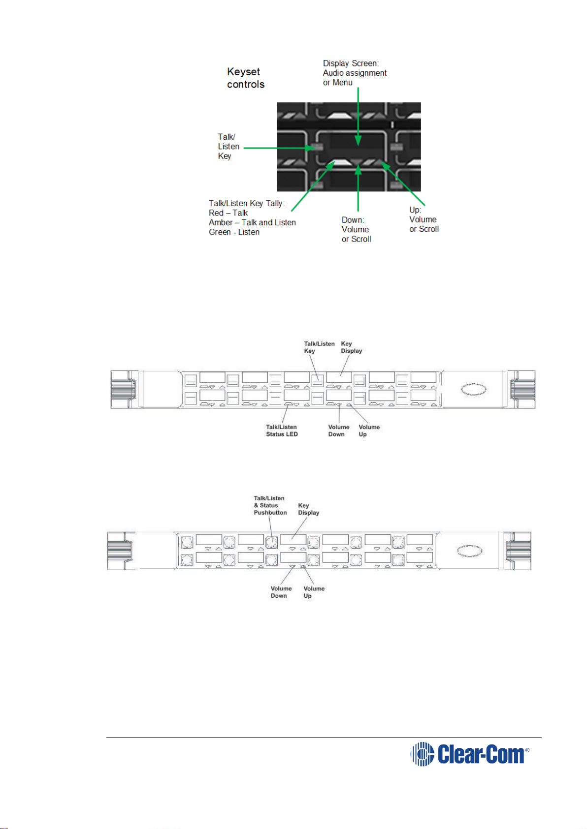
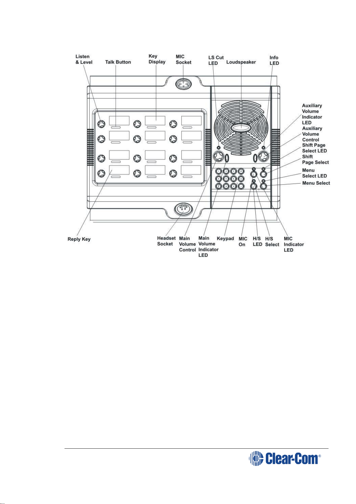
3.3 Front panel lights and controls
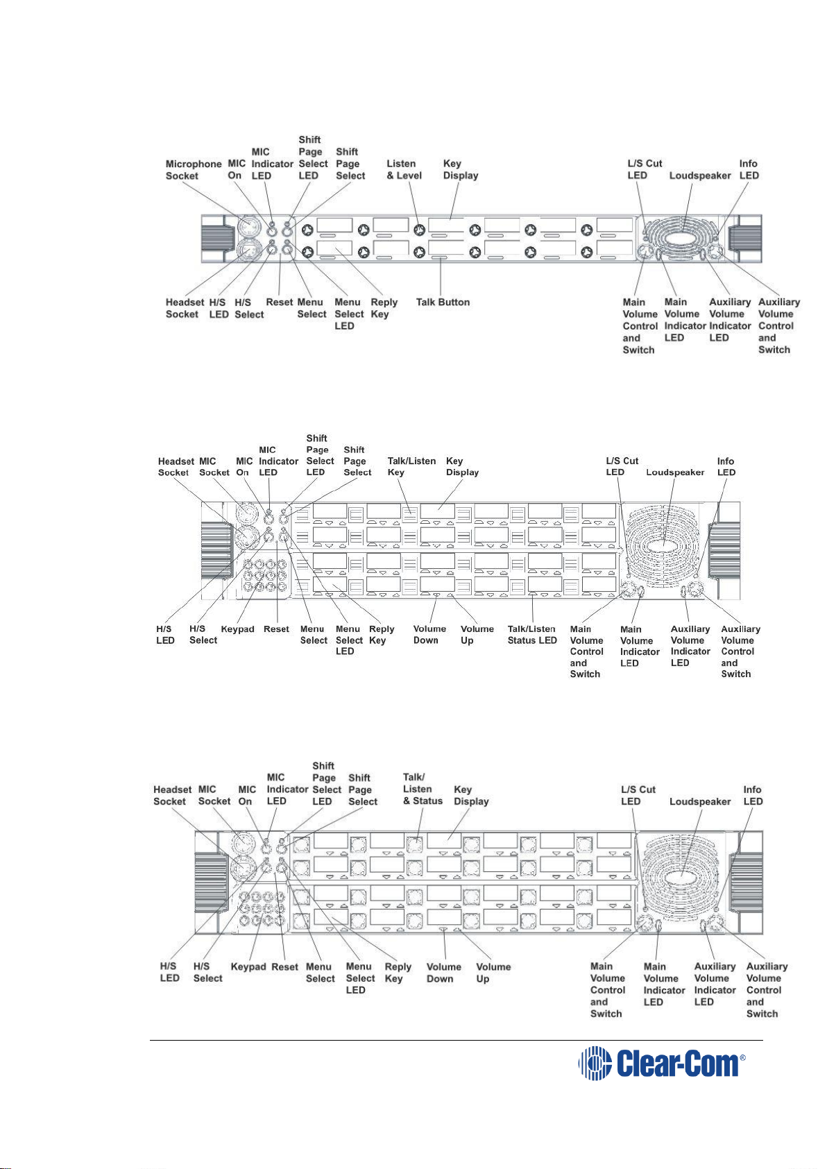
3.3.1 V12LD
Figure 3-1: V12LD front panel lights and controls
3.3.2 V12PD
Figure 3-2: V12PD front panel lights and controls
Page 14
V-Series Panels | User Guide (draft, not yet released)
Page 14
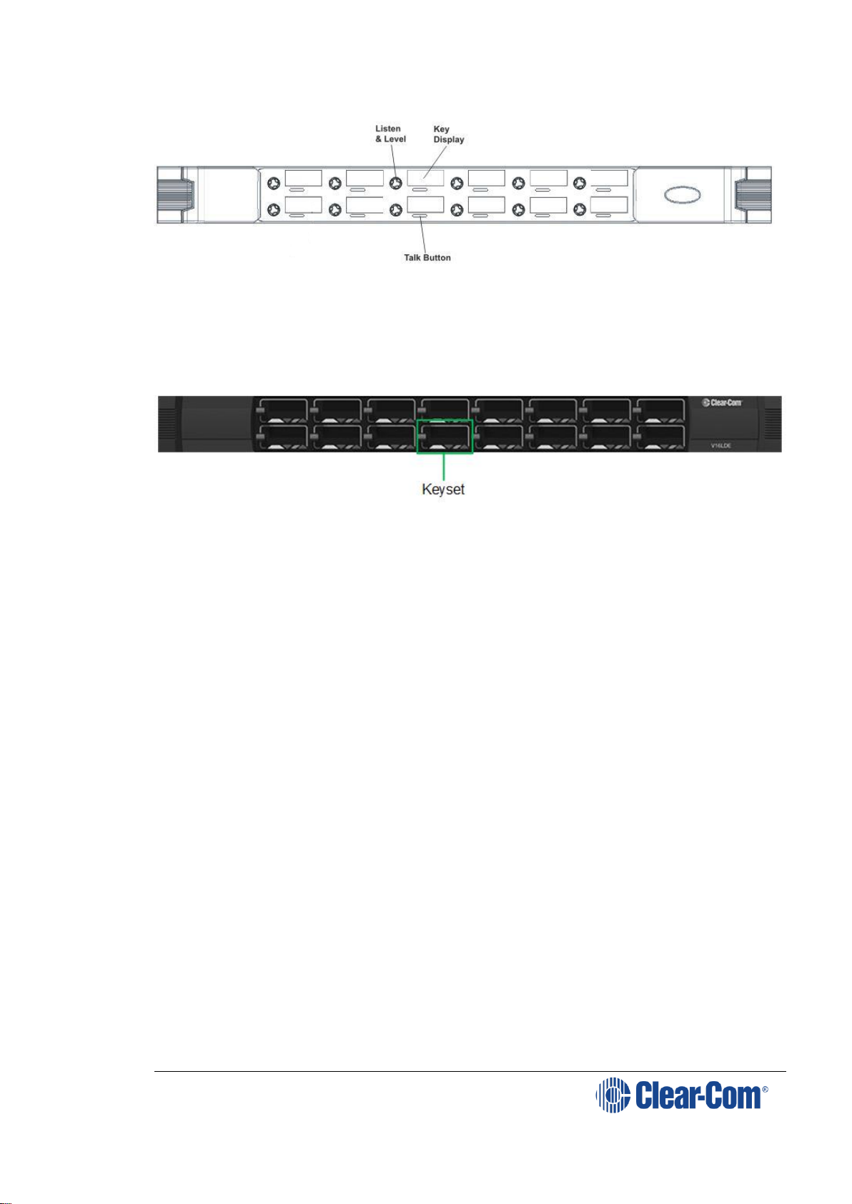
3.3.3 V12RD
Figure 3-3: V12RD front panel lights and controls
3.3.4 V24LD
Figure 3-4: V24LD front panel lights and controls
3.3.5 V24PD
Page 15
V-Series Panels | User Guide (draft, not yet released)
Page 15
Figure 3-5: V24PD front panel lights and controls
3.3.6 V24RD
Figure 3-6: V24RD front panel lights and controls
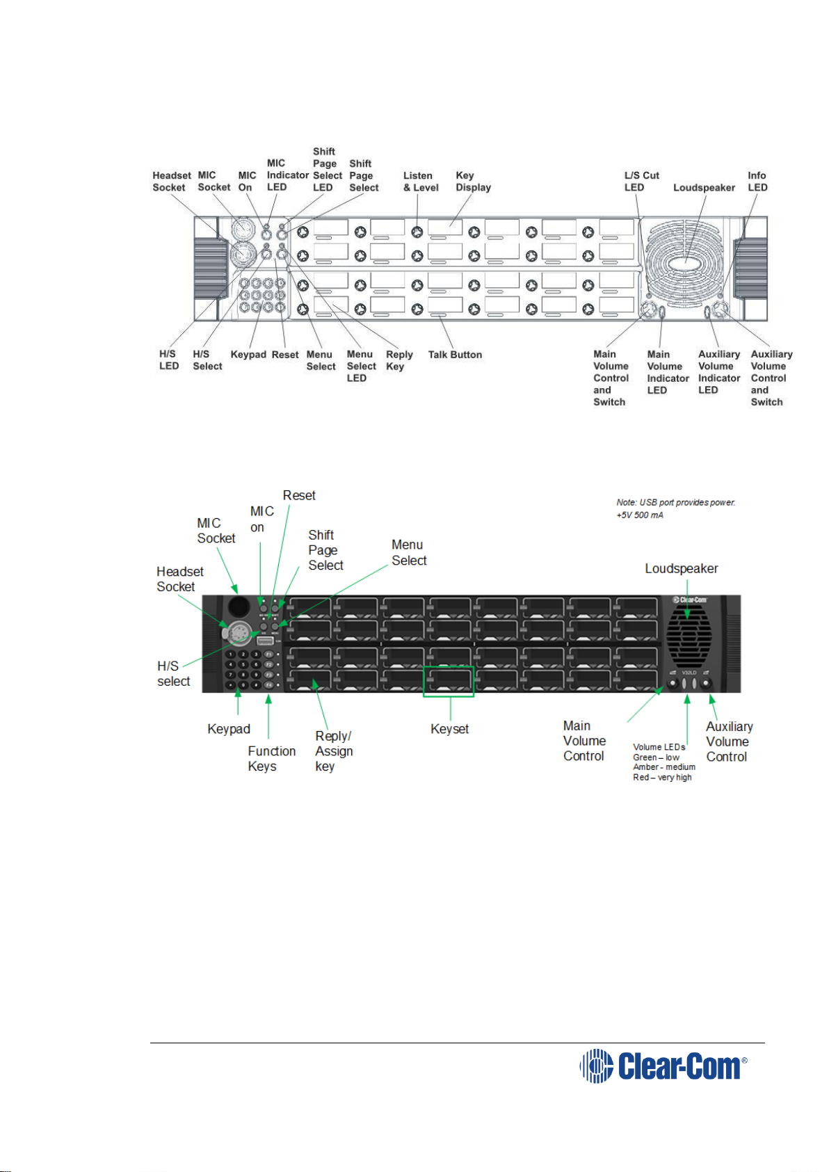
3.3.7 V32LD
Page 16
V-Series Panels | User Guide (draft, not yet released)
Page 16
Figure 3-7 V32LD front panel controls
3.3.8 V12LDE
Figure 3-8: V12LDE front panel lights and controls
3.3.9 V12PDE
Figure 3-9: V12PDE front panel lights and controls
Page 17
V-Series Panels | User Guide (draft, not yet released)
Page 17
3.3.10 V1RDE
Figure 3-10: V12RDE front panel lights and controls
3.3.11 V16LDE
Figure 3-11 V16LDE expansion panel
See Figure 3-7 V32LD front panel controls above for keyset controls.
Page 18
V-Series Panels | User Guide (draft, not yet released)
Page 18
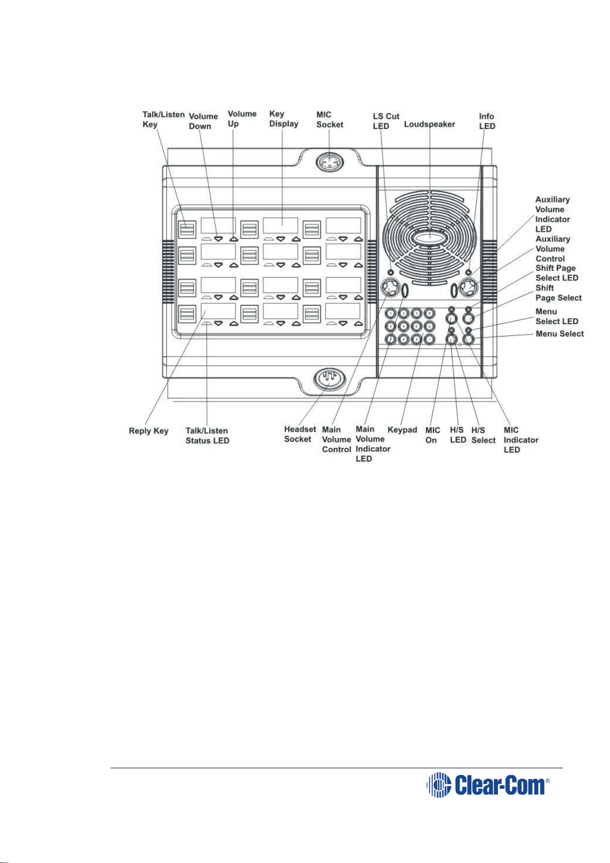
3.3.12 V12LDD
Figure 3-12: V12LDD front panel lights and controls
Page 19
V-Series Panels | User Guide (draft, not yet released)
Page 19
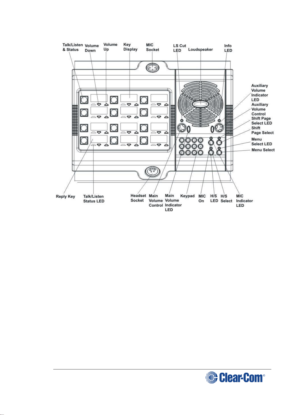
3.3.13 V12PDD
Figure 3-13: V12PDD front panel lights and controls
Page 20
V-Series Panels | User Guide (draft, not yet released)
Page 20
3.3.14 V12RDD
Figure 3-14: V12RDD front panel lights and controls
3.4 Key display window
The key display window is located next to the selection pushbutton, lever key
or rotary control.
You can access assigned labels either by pushing the selection control
(pushbutton and rotary panels) or toggling (lever key panels). Each key display
window can be assigned as many as nine labels, one each from the main page
and the eight shift pages. A label may either:
Represent a talk or listen path to a panel, interface card or module,
Fixed Group, or partyline.
Activate a programmable control function.
The key display window can display up to ten Latin or Katakana characters, or
five Kanji characters, together with status indicators for the key. These status
indicators are:
Currently selected page.
Latched talk indicator.
Latched listen indicator.
Panel monitoring indicator.
Page 21
V-Series Panels | User Guide (draft, not yet released)
Page 21
Microphone indicator.
Incoming VOX indicator.
Antenna active indicator.
Destination type indicator (for example, a partyline, IFB, or Fixed
Group).
Remote panel connection.
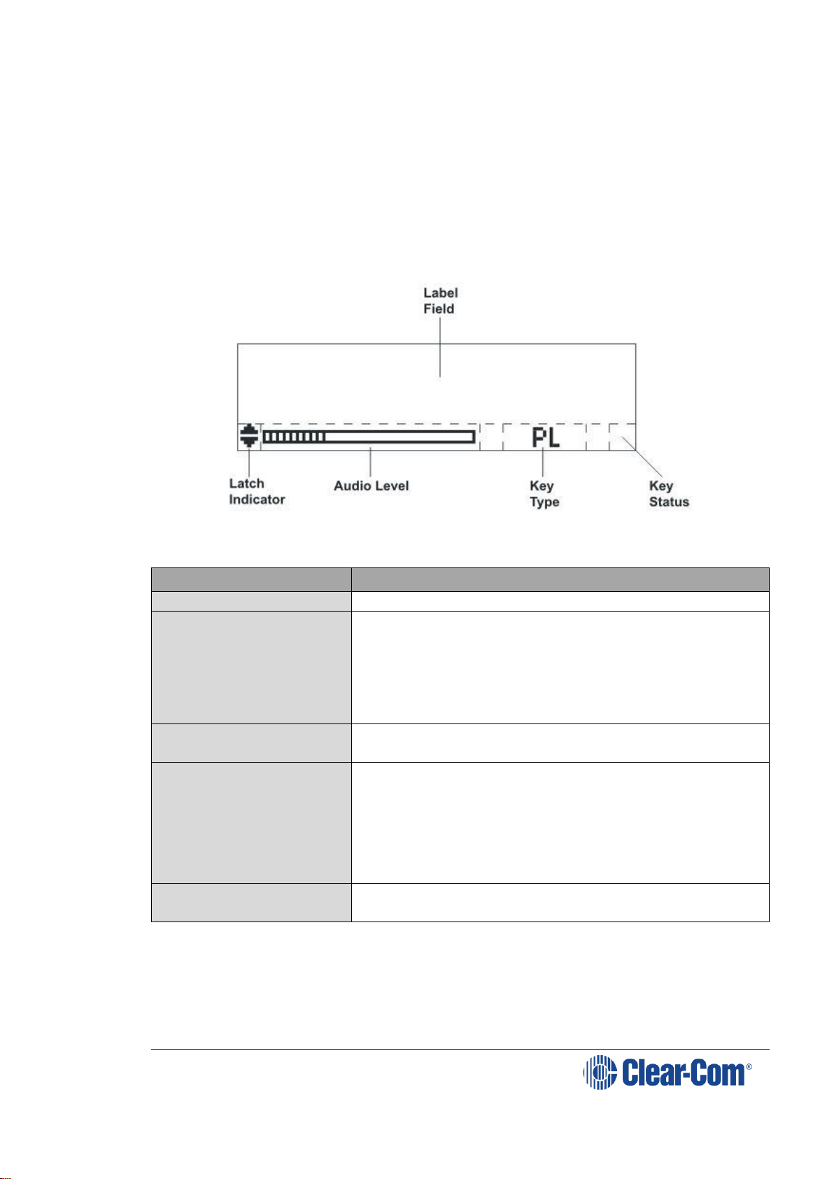
3.4.1 Navigating the key display window
Figure 3-15: Navigating the key display window
Feature
Description / comments
Label Field
10 character field for the key label.
Latch Indicator
Indicates the talk/listen status of the key.
A down arrow indicates that the key is a latched
talk key, an up arrow indicates a latched listen key.
Both arrows together indicate a latched talk and
listen key.
If no arrows are displayed the key is not latched.
Audio Level
A bar graph indicating the audio level set on that
route.
Key Type
Indicates the type of route or action the panel key
is
connected to:
PL = Party Line
IFB = Interruptible Foldback
FG = Fixed Group (includes stacked keys)
Key Status
Displays an icon indicating the status of this key
(see Figure 3-16: Key Status icons).
Table 3: Navigating the key display window
Page 22

V-Series Panels | User Guide (draft, not yet released)
Page 22
Figure 3-16: Key Status icons
3.4.2 Key display window controls
Figure 3-17: Lever key display window controls
Figure 3-18: Pushbutton key display window controls
Page 23

V-Series Panels | User Guide (draft, not yet released)
Page 23
Figure 3-19: Rotary key display window controls
3.4.3 Navigating the Reply key display window
By default, the Reply key is placed in the lower left corner of the panel. You
can move this to any other position from panel programming in the EHX
software.
Note: From the EHX Software, you can enable dual Reply keys. The second Reply key
appears by default directly to the right of the first Reply key. If this position is
already in use, you can either overwrite it or select another position on the
panel. For more information, see the EHX Software User Guide.
Note: You can only reply to the last two calls. Calls are not stacked.
The following points apply to dual Reply keys:
If neither Reply key has incoming calls, the first Reply key is always
populated first.
If both Reply keys have incoming calls, another incoming call replaces
the older of the two original incoming calls.
If a Reply is latched, it will not be replaced by another incoming call.
If both Reply keys are latched, further incoming calls will be heard but
will not appear on the Reply keys.
Only available on V-Series panels.
Figure 3-20: Navigating the Reply key display window
Page 24
V-Series Panels | User Guide (draft, not yet released)
Page 24
Feature
Description / comments
Label Field
10 character field for the Reply / caller label.
Latch Indicator
Indicates the latch status of the key.
As the Reply key is non-latching these indicators
are not displayed.
Shift Page
The number of the current shift page. Only the
current page number is displayed, with the digit in
the position shown in the illustration.
Key Type
Indicates the type of route or action the Reply key
is connected to.
When replying to an incoming call from a partyline,
Fixed Group or IFB the caller port is displayed
rather than the partyline, Fixed Group or IFB. The
reply key only connects to the caller.
Panel Monitoring
Displays an ear icon if the panel is being
monitored.
Table 4: Navigating the reply key display window
3.5 Supported fonts in V-Series panels
Font
Description / comments
Basic Latin
The backslash is a Yen character. This is a size-maximized
font (no descenders, lower-case characters are not
relative in size to upper-case characters). This covers
Unicode 32 to 127 (decimal), 0x20 to 0x7F (hex).
The V-Series panel display will support ten characters.
Cyrillic
This is a normal, relatively-sized font. Covers Unicode
1024 to 1279 (decimal), 0x400 to 0x4FF (hex) with some
missing characters.
The V-Series panel display will support ten characters.
Hiragana
This covers the codepoint range 12352 to 12447
(decimal), 0x3040 to 0x309F (hex).
The V-Series panel display will support five characters.
Full-width
Katakana
The V-Series panel display will support five characters, as
this is a normal width font.
This covers the codepoint range 12448 to 12543
(decimal), 0x30A0 to 0x30FF (hex) with some missing
characters.
Kanji
Displays 17,000 out of the 21,000 characters. This covers
the codepoint range 19968 to 40895 (decimal), 0x4E00 to
0x9FBF (hex).
The V-Series panel display will support five characters.
Hangul
The range is 44032 to 55215 (decimal), 0xAC00 to 0xD7AF (hex).
The V-Series panel display will support five characters.
Page 25

V-Series Panels | User Guide (draft, not yet released)
Page 25
Font
Description / comments
Half-width
Katakana
The codepoint range is 65376 to 65440 (decimal), 0xFF60
to 0xFFA0 (hex).
The V-Series panel display will support ten characters.
Arabic
The character range supported on the V-Series panel is
the Basic Arabic character set 0x0600 to 0x06FF.
Table 5: Supported fonts
3.6 What’s new in Eclipse-HX v. 9.0
2RU 32 lever panel (V32LD)with:
Improved dial pad
4 programmable function keys for easier panel
operation
1 RU 16 lever key panel (V16LDE)
Page 26
V-Series Panels | User Guide (draft, not yet released)
Page 26
4 Installing V-Series panels
This chapter describes how to install V-Series panels, including expansion
panels. It also describes how to install the optional two additional IP channels
that are available.
4.1 Placing panels
4.1.1 Placing rack mounted panels
Locate all panels at comfortable heights for operation and leave at least 2
inches (51 mm) of clearance behind the rear of the panel’s chassis to allow for
cable connectors.
Expansion panels are usually installed next to or near the main panel. Leave at
least 2 inches (51 mm) of clearance behind the rear of each expansion panel to
allow for cable connectors.
Connect expansion panels using straight through 8-way shielded CAT5 cable
with RJ45 connectors.
Note: Expansion panels can be connected to the main panel in a daisy chain using
cables not more than 16 ft (5 m) long between each panel. The cable length of
any daisy chain of panels must not exceed 24 ft (7.5 m) in total.
4.1.2 Placing desktop panels
Desktop panels can be placed on a flat surface or they may be used as wall
mounted panels. Where desktop panels are placed on a flat surface leave at
least 2 inches (51 mm) of clearance behind the rear of the panel to allow for
cable connectors.
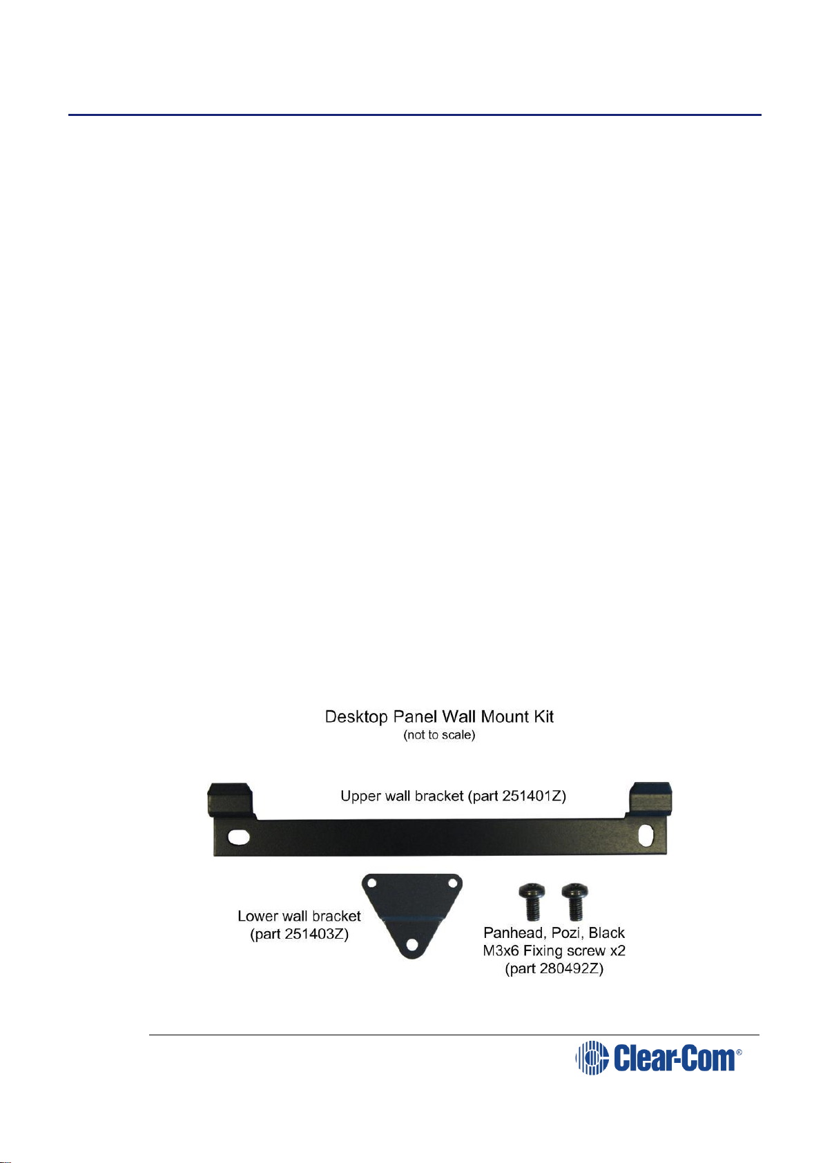
To wall mount a desktop panel:
1) Check the contents of the panel fixing kit provided with the desktop
panel as shown below:
Figure 4-1: Desktop panel wall mounting kit
Page 27

V-Series Panels | User Guide (draft, not yet released)
Page 27
2) Rotate the front panel, so that the controls and display will face
upwards when wall mounted:
3) Remove the eight countersunk screws that hold the front of the panel
in place (the countersunk screws are located on the ends of the panel,
four on each end)
Note: Retain all the screws and remove the front panel assembly.
Figure 4-2: Countersunk screws in desktop panel
Note: The cables connecting the front panel electronics to the main
PCB are long enough to allow the panel front to be removed
and rotated without having to unplug any of the cables.
4) Rotate the front panel 180 degrees taking care not to pull on any of the
cables and reposition it. Ensure that no cables are trapped before
refitting the screws.
5) Apply pressure to the panel front to align the screw holes and fit the
top and bottom screws loosely on each side before fitting the remaining
screws and tightening all the screws.
When completed the front panel will be upside down when the panel
is standing on a flat surface.
Page 28
V-Series Panels | User Guide (draft, not yet released)
Page 28
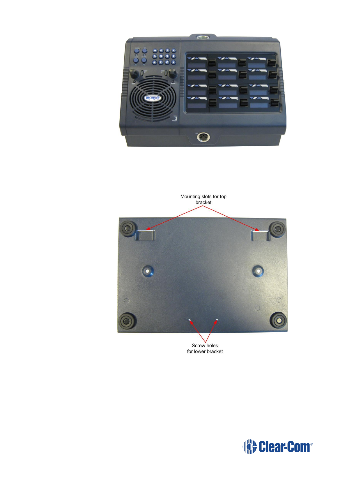
Figure 4-3: ‘Upside down’ desktop panel (for wall mounting)
6) Attach the upper wall bracket to the wall in the required position using
suitable fixings. Allow enough clearance below for the panel for the
lower fixing plate and the cable connections.
Figure 4-4: Desktop casing (without lower bracket)
7) Use the two fixing screws to attach the lower wall bracket to the rear of
the desktop panel so that the offset part of the plate faces away from
the panel body.
Page 29
V-Series Panels | User Guide (draft, not yet released)
Page 29
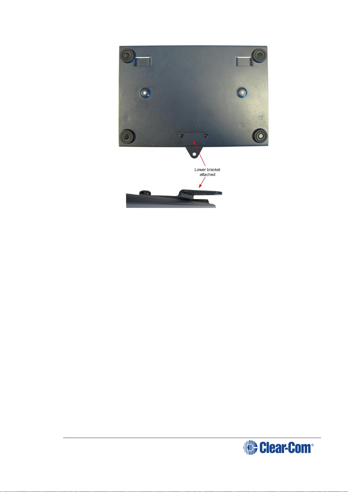
Desktop with Lower Bracket Fitted
Figure 4-5: Desktop casing (with lower bracket attached)
8) Hang the panel on the upper wall bracket and mark the position of the
screw hole for the lower bracket on the wall. Remove the panel and
place a suitable fixing for the lower wall bracket.
9) Replace the panel on the upper bracket and attach the lower wall
bracket to the fixing. Attach the cables to the connectors and power the
panel up.
4.1.3 Placing expansion panels
The following section describes how to install the following optional, accessory
key panels:
The V12LDE Lever Key Expansion Panel adds 12 lever key talk/listen
selectors to a panel.
The V12PDE Pushbutton Expansion Panel adds 12 pushbutton
talk/listen selectors to a panel.
The V12RDE Rotary Expansion Panel adds 12 rotary talk/listen
selectors to a panel.
The V16LDE Lever Key Expansion Panel adds 16 lever key talk/listen
selectors to a panel.
The installation procedure is identical for these panels.
Page 30

V-Series Panels | User Guide (draft, not yet released)
Page 30
Note: Expansion panel types (lever key, pushbutton or rotary) may not be mixed in a
daisy chain of such panels and must be connected to a main panel of the same
type.
Note: The V16LDE expansion panel can only be used with the V32LD panel.
Only one rack unit (1RU) of a standard Electronics Industry Association
equipment rack is required for each expansion panel. The panels’ compact size
makes them ideal for use in TV control rooms, edit suites, mobile OB vans, and
any other location where many talk/listen keys are necessary but space it at a
premium.
All panels provide 12 or 16 additional selectors with displays.
4.1.3.1 Mounting
All accessory panels are mounted in a standard 19-inch wide (48.3 cm)
standard Electronics Industry Association rack, requiring one unit of rack space
each. Leave at least 2 in. (51 mm) of clearance behind the rear of the chassis
to allow for cable connectors.
4.1.3.2 Power
Each expansion panel is powered by an external power supply which may be
mounted on the back of the panel using the mounting clip provided. To connect
the power supply to an expansion panel, route the transformer’s output lead to
the power connector on the back of the panel. This is a 4 pin connector.
4.1.3.3 Panel connection
A cable is supplied with each panel to connect it to a main panel or to
additional expansion panels. The cable is a 6-ft. long (1.8 m) CAT5 cable with
RJ45 connectors at each end. If custom length cables are to be made, they
should be made with cable with 22 to 24 AWG wire. The pins should be wired
one-to-one between the RJ45 connectors. The maximum distance between the
panel and the last expansion panel should be 25 ft. (7.6 m).
To connect an expansion panel to a main panel:
1) Plug one end of the CAT5 cable into the RJ45 expansion socket on the
back of the main panel.
2) Plug the other end of the CAT5 cable into the input connector on the
back of the expansion panel.
To connect an additional accessory panel:
1) Plug the CAT5 cable into the output connector of the last expansion
panel in the chain.
2) Plug the other end of the CAT5 cable into the input connector of the
new expansion panel. More panels can be added by using this daisychaining method.
The numbering of expansion selectors follows the order of the daisy chaining.
Page 31

V-Series Panels | User Guide (draft, not yet released)
Page 31
4.1.3.4 Panel configuration
After physically placing the expansion panels and connecting them to a main
panel, the expansion panels must be programmed in ECS / EHX
For more information, see your ECS / EHX documentation.
4.2 Wiring V-Series panels
This section provides detailed wiring diagrams for V-Series panels.
Eclipse / Eclipse HX uses shielded CAT5 cable between the panel and the
matrix, and between panels and expansion panels using the industry standard
RJ-45 connector.
Note: For detailed wiring information concerning Eclipse / Eclipse HX connections, see
the Eclipse / Eclipse HX Installation Guide.
V Series panels also provide a LAN connection using the industry standard RJ45 connector. If the connection is directly to a PC, use a CAT5 crossover cable
to connect to the LAN port. If a hub or switch is being used, use a straight
CAT5 cable.
To connect to external devices, use the GPIO connector with the DB-25F
connector, and the auxiliary audio connector with the DB-25M connector.
The external panel power supply is normally held in a mounting bracket on the
rear of the panel. If required, you can place the power supply away from the
panel. This enables you to remove the power supply mounting bracket from
the panel, saving space.
The following sections describe:
Connecting the panel to the matrix.
Connections between panels and local devices.
Connections between panels and expansion panels.
Note: In the V-Series rear panel diagrams in this section, the Matrix Connector (RJ-
45) corresponds to the EXT0 connection that is used when panels have
additional IP channels. See 4.3 IP connection to matrix.
Page 32

V-Series Panels | User Guide (draft, not yet released)
Page 32
4.2.1 V-Series main panel rear connectors (no AES-3 or T-
Adapter)
Figure 4-6: V Series main panel rear connectors (no AES-3 or T-adapter)
4.2.2 V-Series main panel rear connectors (AES-3)
Figure 4-7: V Series main panel rear connectors (AES-3)
4.2.3 V-Series main panel rear connectors (T-Adapter) (Now
obsolete)
Figure 4-8: V-Series main panel rear connectors (T-Adapters)
Page 33

V-Series Panels | User Guide (draft, not yet released)
Page 33
4.2.4 V Series expansion panel rear connectors
Figure 4-9: V-Series expansion panel rear connectors
4.2.5 V-Series desktop panel rear connectors (no AES-3 or T-
Adapter)
Figure 4-10: V-Series desktop panel rear connectors (no AES-3 or T-Adapter)
Power
Supply
(24VDC)
GPIO
(DB25F)
LAN
(RJ45)
Auxiliary
Audio
(DB25M)
Matrix
Port
(RJ45)
Expansion
panel
(RJ45)
Page 34

V-Series Panels | User Guide (draft, not yet released)
Page 34
4.2.6 V-Series desktop panel rear connectors (AES-3)
Figure 4-11: V-Series desktop panel rear connectors (AES-3)
4.2.7 V Series desktop panel rear connectors (T-Adapter)
(Now obsolete)
Figure 4-12: V-Series desktop panel rear connectors (T-Adapter)
Power
Supply
(24VDC)
GPIO
(DB25F)
LAN
(RJ45)
Auxiliary
Audio
(DB25M)
Matrix
Port
(RJ45)
Expansion
Panel
(RJ45)
AES-3
RJ-45
Connector
AES-3
BNC
Connector
Power
Supply
(24VDC)
GPIO
(DB25F)
LAN
(RJ45)
Auxiliary
Audio
(DB25M)
Matrix
Port
(RJ45)
Expansion
Panel
(RJ45)
T-Adapter
RJ-45
Connector
Page 35

V-Series Panels | User Guide (draft, not yet released)
Page 35
4.2.8 Mains power cord
The V-Series panels are powered by an external power supply which may be
mounted in a clip on the back of the panel or located away from the panel. If
the power supply is not mounted in the clip on the rear of the panel the clip
can be detached to save space by removing the two mounting screws.
The cord to connect the external power supply to the mains supply must
conform to the following:
The mains power cord shall have an IEC C13 connector at one end and
a mains power plug at the other end.
An IEC C13 plug has three pins, the center pin carrying the earth /
ground. The other two pins carry neutral and live circuits.
The conductors of the mains cords shall have adequate cross-sectional
area for rated current consumption of the equipment.
The mains plug that connects to the mains supply must be approved
for use in the country where the equipment is to be used.
The mains power cord must be an IEC mains power cord complying
with standard IEC60320; IEC320/C13.
Mains power cords used in the U.S. must also comply with standard
UL817.
The equipment must be connected to a mains socket outlet with a
protective earthing connection.
Where the mains plug or an appliance coupler is used as the disconnect
device, the disconnect device shall remain readily operable.
4.2.9 Power connector wiring
The power supply is a 4 pin socket which is connected to an external 24V power supply.
The pinout for the connector is shown below.
Figure 4-13: 4-pin power socket
Page 36

V-Series Panels | User Guide (draft, not yet released)
Page 36
Pin
Description / comments
1
Not connected
2
24VDC
3
Not connected
4
0V
Table 6: 4-pin power socket
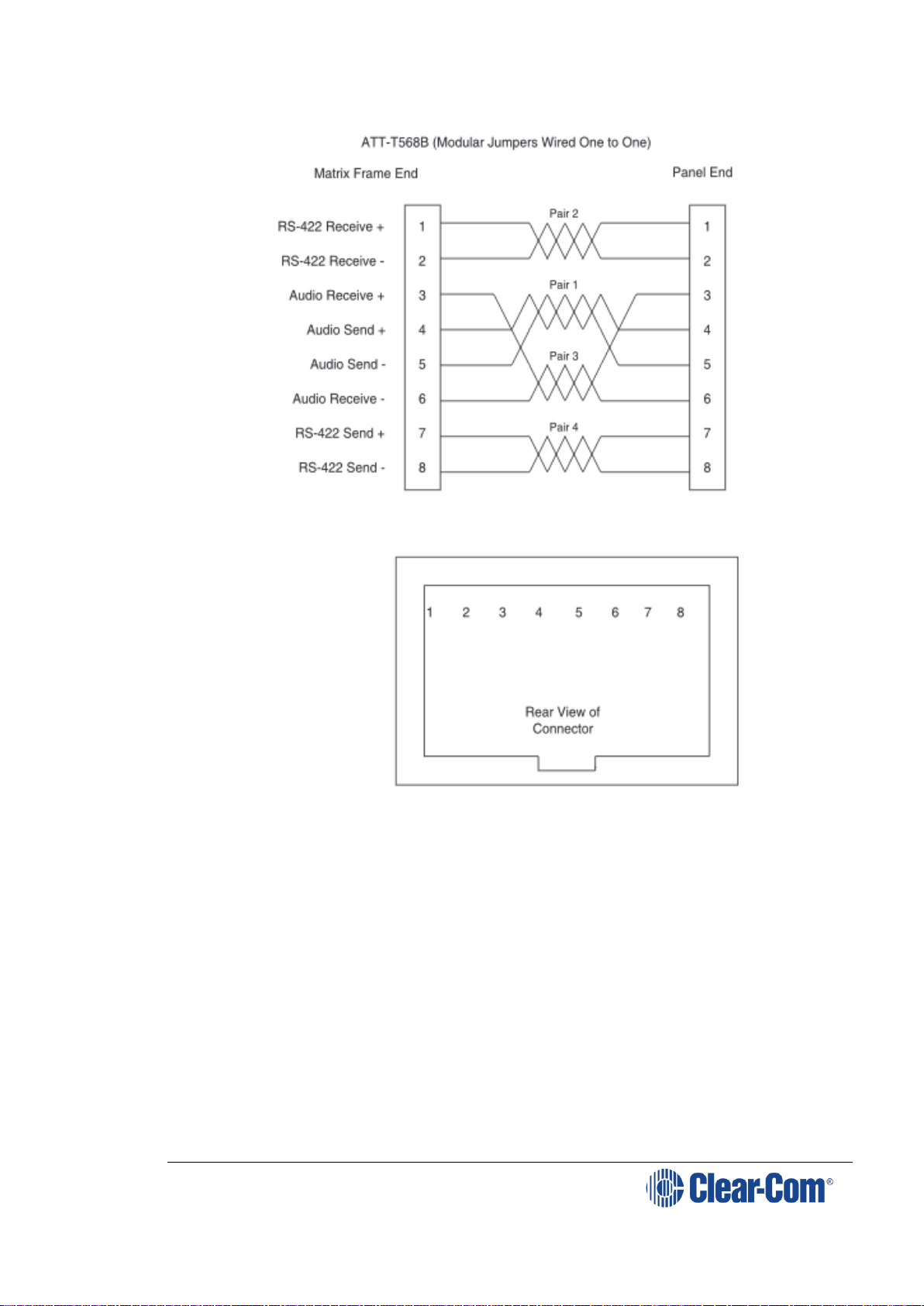
4.2.10 Analog matrix to panel wiring
The analog audio RS-422 data communications module uses a 4-pair wiring
scheme between the matrix and panels. This module requires an MVX-A16 card
in the matrix.
Four-pair analog wiring is wired with shielded CAT5 RJ-45 cable:
Pair 1 transmits analog audio from the matrix port to the panel.
Pair 2 transmits RS-422 data from the panel back to the matrix card
port.
Pair 3 transmits analog audio from the panel to the matrix card port.
Pair 4 transmits RS-422 data from the matrix port back to the panel.
Page 37
V-Series Panels | User Guide (draft, not yet released)
Page 37
Figure 4-14: Matrix to panel wiring (analog)
4.2.11 Matrix panel GPIO connector wiring
Most input/output devices (other than the matrix, expansion panels and
auxiliary audio devices) are connected to the panel via the GPIO connector.
This connector is also used to connect up to two channels over IP. These
channels
Page 38

V-Series Panels | User Guide (draft, not yet released)
Page 38
Figure 4-15: GPIO connector pinout
Pin
Description
Pin
Description
1
Panel Mute relay
output Normally
Closed
14
Panel Mute output relay Common
2
Panel Mute relay
output Normally Open
15
Panel Aux output relay Normally
Closed
3
Panel Aux output
relay Common
16
Panel Aux output relay Normally
Open
4
Not connected
17
Not connected
5
Not connected
18
Not connected
6
Not connected
19
Not connected
7
Not connected
20
5V
8
0V
21
5V 9 0V
22
Opto-isolated input A1
10
Opto-isolated input
B1
23
Opto-isolated input A2
11
Opto-isolated input
B2
24
Opto-isolated input A3
12
Opto-isolated input
B3
25
Opto-isolated input A4
13
Opto-isolated input
B4
Table 7: GPIO connector pinout
Note: The Relay 1 and 2 outputs on the GPIO connector are referred to in ECS / EHX
Controls as Panel mute relays and Panel AUX relays respectively.
4.2.12 Programmable Relay contacts
Each panel includes two relays which are:
Controlled by the matrix.
Independent of the local panel function.
These relays can be assigned to any label(s) in the system, which will activate
whenever a talk or listen is set to that label(s).
Note: If you simply wish to trigger a relay, assign the relay to a control label. For
more information, see your ECS / EHX documentation.
The relay can activate an external device, such as an applause light in a studio,
a cue light, or a security door lock. Any programmable relay in the system can
Page 39

V-Series Panels | User Guide (draft, not yet released)
Page 39
be activated from any panel in the system, including a direct-inward-access
caller.
Figure 4-15: GPIO connector pinout shows the wiring of the relay contacts
to the GPIO connector.
Both normally open and normally closed contacts are provided. They are rated
at 1 Amp at 24 V DC. This relay is not designed for switching mains AC line
voltage. To switch an external device running on mains AC line voltage, use an
external relay (or other switching mechanism) activated by this relay.
4.2.13 Opto-isolated inputs
Each main panel provides four opto-isolated inputs using the GPIO interface.
Each input consists of a pair of pins on the GPIO with an operating range of 4V
to 30V DC or AC. These inputs can be used for user programmable functions
set up by ECS / EHX to execute other actions within the system such as
switching a microphone on or off.
Input 3 (pins A3/B3) is preassigned in ECS to trigger the Reply Key function
while inputs 1 and 2 (pins A1/B1 and A2/B2) are available for assignment
in ECS / EHX in Advanced Settings > Logic Inputs.
Input 4 (pins A4/B4) is not currently used.
The inputs are operated by applying a voltage between 4V and 30V DC or AC
across the pins so that a current flows through the circuit and is detected by
the opto-coupler.
The voltage may be derived from the panel itself using the 5V and 0V pins on
the GPIO or it may be from an external source. An example is a circuit using a
footswitch to activate the panel microphone using logic input 1.
Page 40

V-Series Panels | User Guide (draft, not yet released)
Page 40
Figure 4-16: Example GPIO logic input wiring
In the above example, pressing the footswitch applies 5V DC from the panel
between B1 and A1. This enables the detection of a logic input.
If logic input 1 has been configured in ECS / EHX to activate the Mic On/Off
function the footswitch could be used to control the panel microphone.
4.2.14 Auxiliary audio connector
The auxiliary audio connector allows additional audio inputs and outputs to be
connected to the panel.
Figure 4-17: Auxiliary audio connector
Pin
Description
Pin
Description
1
Headset 2 MIC +ve
14
Headset 2 MIC -ve
2
Headset 2 Left Ear
15
Headset 2 Left Ear Ground
3
Headset 2 Right Ear
16
Headset 2 Right Ear Ground
4
Headset 2 PTT 1
17
Headset 2 PTT 2
Page 41

V-Series Panels | User Guide (draft, not yet released)
Page 41
5
0V
18
0V 6 0V
19
0V
7
External Output 2
+ve
20
External Output 2 -ve
8
External Output 1
+ve
21
External Output 1 -ve
9
Hot MIC Output +ve
22
Hot MIC Output -ve
10
Auxiliary Loudspeaker
Output +ve
23
Auxiliary Loudspeaker Output -ve
11
External Input 2 +ve
24
External Input 2 -ve
12
External Input 1 +ve
25
External Input 1 -ve
13
0V
Table 8: Auxiliary connector pinout
Note: When wiring headset 2 to use the auxiliary audio connector, Clear-Com
recommends using good quality headphone cable to avoid pickup of electronic
noise by the microphone connection.
Wire the Headset 2 PTTs (pins 4 and 17) so that PTT connects the pin to
ground.
The auxiliary loudspeaker output is at line levels, and auxiliary loudspeakers
cannot be connected directly. Auxiliary loudspeakers must be driven through a
suitable audio amplifier. The line output levels are given in the product
specifications.
4.2.15 AES-3 option to AES-6 interface card
The AES-3 option module adds digital input and output using RJ-45 or coax to
V-Series main panels.
If the AES-3 digital interface option is used to connect the V-Series main panel
to the matrix it must be connected to an AES-6 Digital Interface instead of the
MVX-16 serial ports on the matrix.
Note: For more information about the AES-6 digital interface, see the AES-6
Manual.
Figure 4-18: V-Series panel with AES-3 connection
The pinout for the CAT5 cable to connect an AES-6-RJ to a V-Series panel AES3 interface is given in the table below.
Page 42

V-Series Panels | User Guide (draft, not yet released)
Page 42
Pin
Wire color
Description / function
1
White/Orange
not used
2
Orange
not used
3
White/Green
Rx (+)
4
Blue
Tx (+)
5
White/Blue
Tx (-)
6
Green
Rx (-)
7
White/Brown
not used
8
Brown
not used
Table 9: AES-6 to panel wiring (CAT5 cable)
The AES-3 interface RJ45 connection is capable of operation with up to 200m
of screened Cat5e cabling of 110 ohm +/- 10 ohm impedance, with 24 AWG
cores.
If 26AWG or smaller cable is used the maximum cable run may be severely
reduced.
The specification for the coaxial cable required to connect V-Series panels AES3 interfaces to an AES-6-CX card is given below.
Characteristic
Requirement
Nominal impedance
75 Ohm
Insulation
solid polyethylene
Screen
double braided copper
Capacitance
68pF/m or better
Equivalents
BBC PSF 1/3M
BICC TM 3304
Brand Rex GT 851
Table 10: Coaxial cable specification
This type of cable will allow up to 500 meters of cable run between the AES-6CX interface and the panel at the standard 48K sample rate.
Note: A ferrite core must be added to the socket end of each cable. A suitable ferrite
core is Würth Electronik part: 74271132.
If the AES-3 option/AES-6 interface is used to connect the V-Series panel using
a 3rd-party AES-3 network the system setup is as shown below.
Figure 4-19: Panel connected by 3rd party AES-3 network
Page 43

V-Series Panels | User Guide (draft, not yet released)
Page 43
Note: The cable specifications are as stated previously unless the connections to the
3rd party network require different cable specifications. In this case the
customer should contact Clear-Com for advice.
4.2.16 T-Adapter option to DIG-2/DIF-102 interface
Note: The information in this section no longer applies to recent version of EHX
software.
The T-Adapter option module adds 2-wire digital input and output via RJ-45 to
V-Series main panels. If the T-Adapter digital interface option is used to
connect the V-Series main panel to the matrix it must be connected via a DIG2 Digital Interface instead of directly to an MVX-16 analog port on the matrix.
Note: For information on the DIG-2/DIF-102 digital interface, see the DIG-2 manual
and the Interface Module Frames manual.
Figure 4-20: Panel with T-Adapter interface
The pinout for the CAT5 cable to connect a DIG-2 interface to a V-Series panel
T-Adapter interface is given below.
Pin
Wire color
Description / function
1
White/Orange
not used
2
Orange
not used
3
White/Green
not used
4
Blue
Tx/Rx (+)
5
White/Blue
Tx/Rx (-)
6
Green
not used
7
White/Brown
not used
8
Brown
not used
Table 11: DIG-2-6 to panel wiring (T-Adapter interface)
The T-Adapter interface RJ45 connection is capable of operation with up to
3000m (10,000ft) of screened 24 AWG Cat5e cabling of 110 ohm +/- 10 ohm
impedance.
Page 44

V-Series Panels | User Guide (draft, not yet released)
Page 44
If 26 AWG screened CAT5e cable is used the maximum cable run is reduced to
2,200m (7,300ft).
Note: A ferrite core must be added to the socket end of each cable. A suitable ferrite
core is Würth Electronik part: 74271132.
4.2.17 LAN connector
The LAN connector is an industry standard RJ45 socket that enables you to
connect the panel to either a network or the Ethernet port of a PC. The LAN
connection is reserved for panel firmware upgrades and future use. This port
can support connection of panel to matrix with one, two or three audio
channels.
Figure 4-21: LAN connector pinout
4.2.18 Expansion panel output
V-Series main panels have an industry standard RJ45 socket allowing up to
eight V Series expansion panels to be daisy chained from it.
Page 45

V-Series Panels | User Guide (draft, not yet released)
Page 45
Figure 4-22: Example of daisy chained panels
The pinout for the expansion panel cable RJ45 connector is given below:
Figure 4-23: Expansion panel connector pinout
The CAT5 cables used to connect V Series main panels to expansion panels and
expansion panels to further expansion panels are wired as straight through and
the same signals are present along the daisy chain.
Each cable connecting a V Series main panel to an expansion panel or an
expansion panel to another expansion panel must not exceed 5 meters in
length, and the total length of any expansion panel daisy chain must not
exceed 7.5metres in length.
Note: If power is removed from an expansion panel within a chain that panel and all
expansion panels after it in the chain will no longer work.
Note: For connections to V12LDE (regulatory model UP160), a ferrite core must be
added to the socket end of CAT5 cable. A suitable ferrite core is Fair-rite part:
0431164951.
4.3 IP connection to matrix
All V-Series panels have a built-in Ethernet/IP interface which can support
multiple independent audio channels to an HX Omega, HX Median or HX Delta
via an IVC-32 matrix card. When you add a V-Series panel in the EHX
Configuration Software, you are prompted to choose the number of additional
IP channels that you require, see 4.3.1 Adding one extra IP channel.
According to your choice, the EHX software automatically provides the V-Series
audio mixer with default settings to make configuration as simple and fast as
possible. The default mixer settings reflect the typical user scenarios, but you
can also manually adjust the mixer settings in the EHX software to customize
your system, or for more advanced requirements. See 4.3.4 Advanced multi
IP channel configurations.
This section describes how to implement more than one audio channel via the
Ethernet/IP connection. The extra audio channels are typically used to connect
to:
A CCI-22 Interface Module for matrix to 2-wire partyline connections.
Page 46

V-Series Panels | User Guide (draft, not yet released)
Page 46
A FOR-22 Interface Module for connecting the matrix to a 4-wire device
with call signaling.
Headsets. These can be binaural, with or without Push To Talk (PTT).
There are also more advanced options including matrix inputs and mixer
control.
There are three connectors on the rear panel of the V-Series panel that can be
routed to the matrix via the IP channels. These are labelled:
Control – this is a DB25 female connector
Aux Audio – this is a DB25 male connector
Matrix (Analogue) – this is an RJ-45 connector
Internally, these are represented as EXT0, EXT1 and EXT2. If there is more
than one IP channel, EXT0 appears at the Matrix (Analogue) connector at the
rear of the panel. When two extra IP channels are added, EXT1 and Ext2 are
on the cable assembly used to implement the added IP channels. If there is
only one IP channel, EXT1 and EXT2 appear at the Control and Aux. Audio
connectors on the rear of panel.
The following sections describe the workflow for typical scenarios where one or
two extra IP channels are required. There is also a section describing more
advanced configurations. See also, the Eclipse HX Configuration Software
Manual.
4.3.1 Adding one extra IP channel
This is typically used if you want to configure the extra IP channel to connect
to a 4-wire interface, or to an analogue or digital partyline. To add on extra IP
channel:
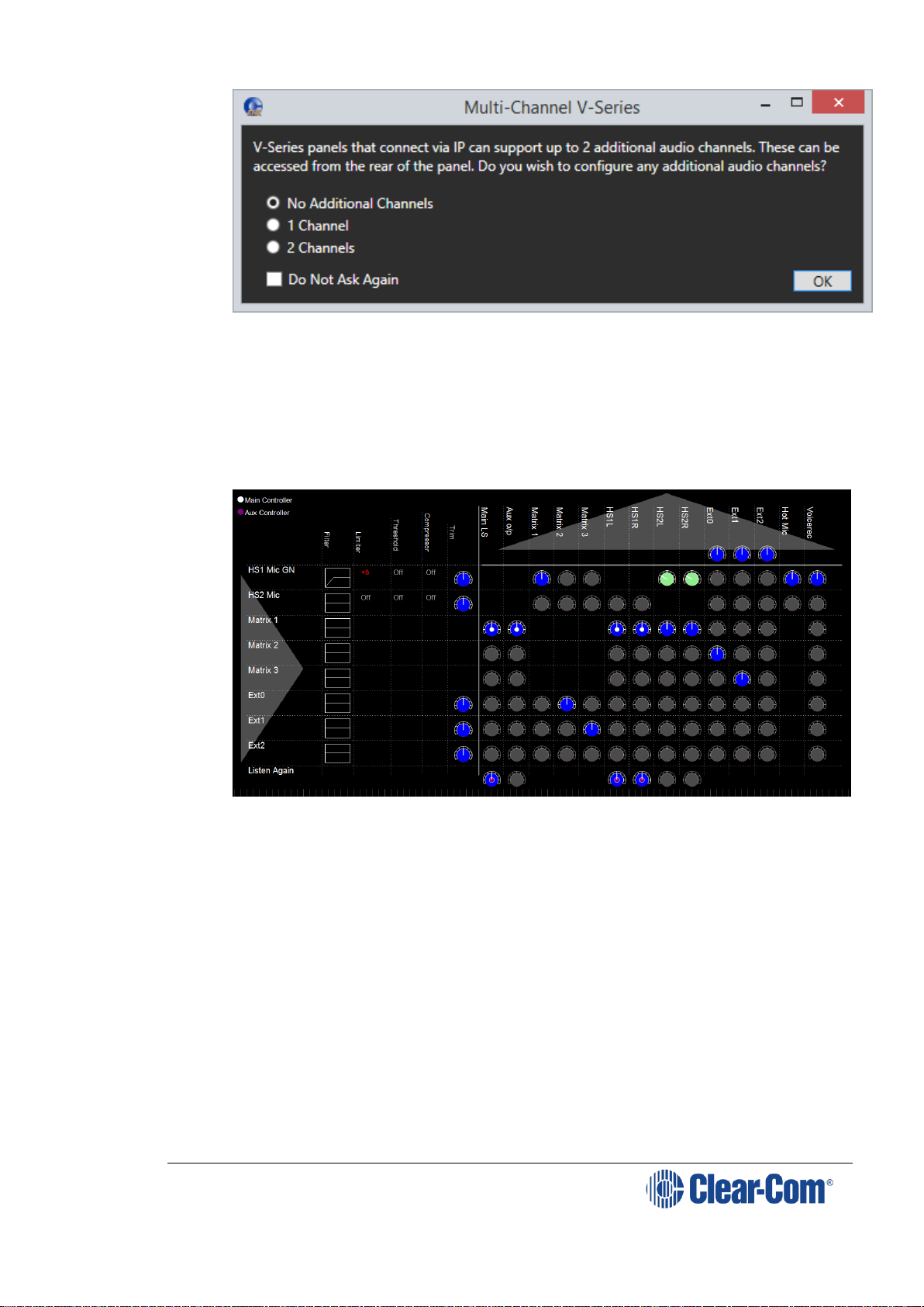
1) From the EHX software, navigate to Cards and Ports > IVC-32 >
Port Function and add the V-Series Panel. The following screen
appears:
Figure 4-24 Multi-Channel V-Series
2) Select 1 Channel. A port labeled Hosted Direct appears under the V-
Series Panel.
3) The Audio Mixer settings automatically set the default layout for one
extra IP channel.
Page 47

V-Series Panels | User Guide (draft, not yet released)
Page 47
Figure 4-25 Audio Mixer for one extra IP channel
Matrix 2 is the added Hosted Direct channel. The default single IP
channel mixer setting has matrix 2 audio routed to and from Ext 1.For
more information about the Audio Mixer, see the Eclipse HX
Configuration Software User Guide.
Note: If required, you can change the default settings. See 4.3.4
Advanced multi IP channel configurations.
4) Connect the V-Series Panel EXT0 connector to the FOR-22, CCI-22 or
HelixNet unit using an RJ-45 crossover cable. The pinouts are shown
below.
Page 48

V-Series Panels | User Guide (draft, not yet released)
Page 48
Figure 4-26 Pinouts for RJ-45 crossover cable
By default, the extra IP channel is configured as Direct, which is used for a 4wire connection. You can change this to make it suitable for a different
application.
5) In the EHX software, navigate to Cards and Ports, and select the
added IP port.
6) From the right-hand side of the window, select Basic Options.
7) From the Module Application list box, select from
Partyline – to connect to an analogue partyline using the CCI-
22 Interface Module.
Two-Way Radio – to connect to a third-party two-way radio
system by using the FOR 22 Interface Module.
Direct – to connect to a 4-wire interface.
HelixNet – to connect to the digital HelixNet partyline.
A partyline, two-way radio or HelixNet interface connected to EXT 0 in
this way provides the same functionality as the same interface
connected directly to an MVX port, for example call signaling Tx and Rx
in the case of the Partyline port application setting.
4.3.2 Adding two extra IP channels
This is typically used if you want to configure two extra IP channels to connect
to a 4-wire interface, or to an analogue or digital partyline.
Note: This configuration requires a cable assembly, see Figure 4-29. Clear-Com
support can assist in the sourcing of this and similar cables.
To add two extra IP channels:
1) From the EHX software, navigate to Cards and Ports > IVC-32 >
Port Function and add the V-Series Panel. The following screen
appears:
Page 49
V-Series Panels | User Guide (draft, not yet released)
Page 49
Figure 4-27 Multi-Channel V-Series
2) Select 2 Channels. Two ports labeled Hosted Direct appear under the
V-Series Panel.
3) The Audio Mixer settings automatically set the default layout for one
extra IP channel.
Figure 4-28 Audio Mixer for two extra IP channels
Matrix 2 and Matrix 3 are the additional IP connections to the IVC-32.
The default mixer settings when two additional channels are selected
are to route Ext 0 to/from Matrix 2 and Ext 1 to/from Matrix 3. This
routing can be changed using the Audio Mixer. For more information
about the Audio Mixer, see the Eclipse HX Configuration Software User
Guide.
Note: If required, you can change the default settings. See 4.3.4
Advanced multi IP channel configurations.
4) Connect the V-Series Panel Matrix (Analogue) port to the one of the
ports in the IVC-32 card in the matrix using an RJ-45 crossover cable.
The pinouts are shown in the section above.
5) Connect the third-party cable harness as follows:
Page 50

V-Series Panels | User Guide (draft, not yet released)
Page 50
Male DB-25 connector to Control on V-Series panel
Female DB-25 connector to Aux.Audio on V-Series panel.
The pinouts for this connector are shown on the next page.
By default, the extra IP channels are configured as Direct, which is used for a
4-wire connection. You can change this to make it suitable for a different
application.
1) In the EHX software, Navigate to Cards and Ports, and select the
added IP port.
2) From the right-hand side of the window, select Basic Options.
3) From the Module Application list box, select from
Partyline – to connect to an analogue partyline by using the CCI-22
Interface Module.
Two-Way Radio – to connect to a third-party two-way radio system
by using the FOR 22 Interface Module.
Direct – to connect to a 4-wire interface.
HelixNet – to connect to the digital HelixNet partyline.
By default, the extra IP channel is configured as Direct, which is used for a 4wire connection. You can change this to make it suitable for a different
application.
A partyline, two-way radio or HelixNet interface connected to EXT 0 in this way
provides the same functionality as the same interface connected directly to an
MVX port, for example; call signaling, Tx and Rx, in the case of the Partyline
port application setting.
With this default mixer setting FOR-22 or CCI-22 can be connected to EXT0
and EXT1. This setting supports both Call signaling and/or PTT signaling to the
external device.
Page 51

V-Series Panels | User Guide
Page 51
Figure 4-29 Pinout diagram for cable harness
5 4 3 2 1
1.6M
GN 1
Y 2
O 3
R 4
BN
D
BL
D
4 WAY MALE XLR (FREE)
2M
1 Y
14
GN
2 BN
15 O
3
BL
16 R
4
17
C
5
18
6
19
7
20
8
21
9
22
10
23
11
24
12
25
13
GN/W
BL/W
BL
GN
1
2
3
4
5
6
7
8
RJ-45 - screened
C
label this connector EXT2
20CM
25 way female D-type , metal shroud
B
O/W 1
O 2
GN/W 3
BL 4
BL/W 5
GN 6
BN/W 7
BN 8
B
label this connector EXT1
1
14
2
15
3
16
4
17
5
18
6
19
7
20
8
21
9
22
A
10
23
11
24
12
25
13
BAT85 DIODES X 5
RJ-45 - screened
A
25 way male D- type , metal shroud
Title
AUDIO CABLE
2M
Size Document Number Rev
A3 <Doc> 3
5 4 3
Date: 2 06/26/2014 Sheet
1
1 of 1
label this connector He adset 1
Page 52

V-Series Panels | User Guide
Page 52
4.3.3 Binaural audio
If you configure the panel for binaural audio, the following default mixer
settings appear in the panel Audio Mixer. This mode is useful for situations
when you require separate audio channels in the left and right headphone
inputs.
Figure 4-30 Audio Mixer for binaural
4.3.4 Advanced multi IP channel configurations
The additional one and two IP channel configurations automatically activate
default settings in the Audio Mixer when they are selected in the EHX software.
You can change these default settings to create a custom configuration. For
example, you can change the default routing in the Audio Mixer.
When port applications other than direct are selected for the hosted ports
panel, GPIOs will be automatically allocated by the software to provide the
requested functionality, for example call signal in the case of partyline. These
GPIOs will continue to be available in the EHX GPI and GPO screens and the
logic of the parallel usage will be OR'd.
For more information about using the Audio Mixer, see the EHX Configuration
Software User Guide.
4.4 Front panel connectors
The V-Series main panels have a microphone connection and a headset
connection on the front.
The microphone connection is always a three pin socket while the headset
connector may be an XLR-4M, XLR-5F or XLR-7M connector.
The pinouts for the connectors are given below.
Page 53

V-Series Panels | User Guide (draft, not yet released)
Page 53
4.4.1 Microphone connector
Figure 4-31: Microphone connector
Pin
Description / comments
1
Screen
2
Microphone input +
3
Microphone input -
Table 12: Microphone connector pinout
Note: Configuration of the wrong type of microphone or headset will degrade or
nullify the audio from the panel or worse still, damage the microphone or
headset.
4.4.2 Headset connectors
The headset connector may be one of three types: XLR-4M, XLR-5F or XLR-
7M.
The pinouts for each type are shown below.
Figure 4-32: XLR-4M headset connector
Pin
Description / comments
1
Microphone Screen
2
Microphone Input
3
Headphone Return
4
Headphone Output
Table 13: XLR-4M headset connector pinout
Page 54

V-Series Panels | User Guide (draft, not yet released)
Page 54
Figure 4-33: XLR-5F headset connector
Pin
Description / comments
1
Microphone Screen
2
Microphone Input
3
Headphone Return
4
Left Headphone Output
5
Right Headphone Output
Table 14: XLR-5F headset connector pinout
Figure 4-34: XLR-7M headset connector
Pin
Description / comments
1
Microphone -ve
2
Microphone +ve
3
Ground
4
Left Headphone Output
5
Right Headphone Output
6
PTT1
7
PTT2
Table 15: XLR-7M headset connector pinout
Page 55

V-Series Panels | User Guide (draft, not yet released)
Page 55
Note: Configuration of the wrong type of microphone or headset will degrade or
nullify the audio from the panel or worse still, damage the microphone or
headset.
The PTT1 and PTT2 functions on an XLR-7 headset or a second headset
connected via the auxiliary audio connector are connected to the logic 1 and
logic 2 inputs.
Headset 1 PTT 1 or headset 2 PTT 1 active will have the same effect as Logic 1
active.
Headset 1 PTT 2 or headset 2 PTT 2 active will have the same effect as Logic 2
active.
PTT is activated by grounding the PTT line.
4.5 Mains AC Power
The panel has a separate, external DC power supply.
The power supply is universal, operating over a voltage range of 100 to 240
VAC and 50 to 60 Hz. The maximum power dissipation is 50 W.
A bracket has been provided to mount this external supply if necessary.
4.6 Panel parameters in ECS / EHX
The following panel parameters are adjustable by selecting options in ECS /
EHX:
Panel Headset Microphone Gain
Headset 2 Microphone Gain
Panel Microphone Gain
Input Level (Volume)
Output Level (Volume)
Aux Level (Volume) Off Limit
Main Level (Volume) Off Limit
Speaker Dim
Page Volume Level
Headset Detect Loudspeaker Cut
All these parameters are set to factory defaults. Most panels should operate at
these default setting. However, some applications may required adjustment.
4.6.1 Headset sidetone
Sidetone is the sound of the user’s voice in his headset.
For information about adjusting sidetone, see your ECS / EHX documentation.
4.6.2 Headset autodetect
V-Series panels can autodetect headsets 1 and 2 and automatically enable
them. Headset auto detect can be set to enabled or disabled via a DIP switch
(SW2) on the main board. As headset insertion can cause a noise on the panel
some users may wish to disable automatic headset detect and use the front
panel button instead to enable and disable the headsets.
To access the DIP switch the rear cover must be removed from the panel.
The DIP switch is located on the right hand edge of the main PCB (looking from
the rear) behind the headset connector.
Page 56

V-Series Panels | User Guide (draft, not yet released)
Page 56
Figure 4-35: DIP switch location (headset detect)
Headset 1 auto detect is controlled by switch 1 on SW2 and headset 2 auto
detect is controlled by switch 2 on SW2.
Figure 4-36: Headset detect DIP switch settings
To enable headset auto detect for a headset set the appropriate switch to ON
(towards the front of the panel).
To disable headset auto detect set the appropriate switch to OFF (towards the
rear of the panel).
4.6.3 Panel microphone gain
The preamplifier gain of the panel microphone can be adjusted over a range of
+20 to +70 dB; the panel microphone gain’s default setting is 50 dB. However,
if two panels are talking to each other at the same time with the panel
microphone gain set to maximum, feedback may occur even if the speaker dim
is set to maximum in ECS / EHX.
Page 57

V-Series Panels | User Guide (draft, not yet released)
Page 57
In this case, it will be necessary to turn the panel microphone gain down.
Similarly, in some noisy environments it may be necessary to turn the panel
microphone gain down and have the operator talk more closely into the
microphone.
Note: For information on adjusting panel microphone gain, see your ECS / EHX
documentation.
4.6.4 Speaker dim
When a panel microphone and a speaker are used together, feedback is
possible.
To reduce this possibility, the panel software will mute (turn down) the speaker
level by some predetermined amount when both the microphone and speaker
are enabled. The speaker mute can be adjusted from 0 to 15 dB (its default
setting is 6 dB).
Note: For information on adjusting speaker mute settings, see your ECS / EHX
documentation.
4.6.5 Page Override
When Page Override is assigned to a label, the audio level at the destination
panel(s) is predetermined.
This function enables you to talk to someone even if their panel volume control
is off (if the destination speaker was off, it will turn on).
The panel speaker output will operate at the predetermined level regardless of
the volume control setting, unless this control is set higher than the
predetermined level.
The page volume level can be adjusted from 0 to 10 in steps of 1 with 0 being
off and 10 being full volume. The page volume level’s default setting is 5.
Note: For information about enabling Page Override, see your ECS / EHX
documentation.
4.7 Panel-to-matrix card baud rate
The RS-422 serial data communication between a panel and other devices
operates at 19.2 k baud by default.
Page 58

V-Series Panels | User Guide (draft, not yet released)
Page 58
5 Using the Front Panel Controls
This chapter describes the functionality of the V-Series front panel controls in
detail, including the small functional differences between lever key panels,
pushbutton panels and rotary control panels.
Note: For a brief description of all the V-Series panels covered by this guide,
including product numbers, see Table 1: V-Series Panels covered by this
guide.
5.1 Mic On
The Mic On/Off button turns the currently selected microphone (gooseneck
microphone or headset microphone) on or off.
When the microphone is, on the red LED will come on to indicate that the
microphone is active. If a panel key is used to establish a talk connection the
panel microphone is automatically enabled and the indicator light is lit.
When the connection is terminated the microphone is automatically disabled.
5.2 Shift Page
By momentarily pressing and releasing the Shift Page button, you can toggle
between the main page and the currently selected shift page.
When you press and hold the Shift Page button for more than 500ms, the
panel is placed in Shift Page mode. The Shift Page menu is shown on the
display and the red indicator LED is lit.
From the EHX Software, you can also enable the shift button to cycle through
consecutive shift pages.
The software now supports named shift pages. This allows the user to give any
shift page a 1 - 10 character name to better identify the use of the page. See
EHX user guide for information on the naming of shift pages.
From the EHX Software, you can select two shift page options:
Selectable Shift Page
Cyclic Shift Pages
To find these options in the EHX Software, navigate to:
Configuration > Preferences > Panel & Key Operation
The V-Series Specific Settings area is located at the bottom of the Panel & Key
Operation window.
Note: If you latch any key on a shift page, it remains latched if you select a different
shift page.
Note: Shift Page Mode: when the Shift Page Menu is open, the keys on the panel
will be color coded.
Bright green: page currently selected
Dim green: keys are configured on the page
5.2.1 Selectable Shift Pages
If this option is enabled in EHX software, the shift button behaves as follows:
Page 59

V-Series Panels | User Guide (draft, not yet released)
Page 59
From the Main page (page 0), a short press or tap displays the last
selected shift page. If no shift page has previously been selected, the
panel displays shift page 1. The Shift LED is lit.
To return to the Main page, short press or tap the shift button. The
Shift LED is off. Pressing and releasing the shift page button toggles
between the Main page and the last selected shift page.
From the Main page, a long press (more than 500 ms) displays a list of
shift pages on the panel display, with an underline on the last selected
shift page. Use the panel button, switch or lever to select any shift
page. The Shift LED is lit.
To return to the Main page, short press or tap the shift page. The Shift
LED is off.
5.2.2 Cyclic Shift Pages
If this option is enabled in EHX Software, the shift button behaves as follows:
From the Main page, a short press or tap displays the next consecutive
shift page in ascending numerical order.
For example, if you have a main page with five shift pages numbered
as follows: M, 1, 2, 3, 5, then a short press or tap on the shift button
will cycle through the shift pages as follows:
M, 1, 2, 3, M, 1, 2, 3 and so on.
Only consecutive pages are cycled, so 5 is not cycled, but can still be
accessed using the shift menu.
Note: The Shift LED is lit on any page other than the Main page.
Note: If shift pages have Local Assignment enabled, a shift page can
cycle even if no keys are assigned to it. For more information,
see the EHX Software User Guide.
From the Main page, a long press (more than 500 ms) displays a list of
shift pages on the panel display. Use the panel button, switch or lever
to select any shift page. The Shift LED is lit.
After selecting a page, short press or tap the shift button to cycle
consecutive pages or long press to return to the list of shift pages.
5.3 Headset Select
The Headset Select button enables you to select the panel headset for audio
output.
When you have selected a headset, the red LED indicator is lit. The panel
microphone is deselected, if active.
5.4 Menu
V-Series panel functions are configured in Menu mode. You enter Menu mode
by pressing and releasing the Menu button.
When the panel enters Menu mode, the display windows are cleared of labels
and the panel menus are displayed. The blue menu LED is lit.
To exit an active menu, press the Menu button again.
Page 60

V-Series Panels | User Guide (draft, not yet released)
Page 60
Note: Access to some panel menus can be disabled in ECS (Eclipse Configuration
Software) / EHX (Eclipse HX configuration software) through Advanced
Settings > Menu Options in Cards and Ports. A PIN code (set in the
configuration software) must be entered to disable access to these menus.
When the PIN code is entered on the panel, access is granted. For more
information, see your ECS / EHX documentation.
5.5 LS Main levels (volume) control
The main levels (volume) control comprises a rotary encoder with push-
switch action and a tri-color loudspeaker volume indicator LED.
The LED volume indications are:
Red - high volume.
Amber - intermediate volume.
Green - low volume.
Turn the volume control clockwise to increase the loudspeaker volume and
anticlockwise to decrease loudspeaker volume.
The loudspeaker cut indicator LED is lit red when the loudspeaker output is
muted. Press the volume control to toggle the loudspeaker cut.
5.6 Auxiliary levels (volume) control
The auxiliary panel levels (volume) control comprises a rotary encoder
with push-switch action and a tri-color loudspeaker volume indicator LED. The
LED volume indications are:
Red - high volume.
Amber - intermediate volume.
Green - low volume.
The auxiliary levels (volume) control sets the volume on the optional external
loudspeaker that you can connect to the auxiliary audio port on the rear of the
panel. Turn the volume control clockwise to increase the loudspeaker volume
and anticlockwise to decrease loudspeaker volume.
Press and release the auxiliary volume control to play back messages stored on
the Listen Again system (see next section).
5.7 Listen Again
Note: The Listen Again feature is configured in ECS / EHX. For more information,
see your ECS / EHX documentation.
Pressing the auxiliary volume control switch momentarily activates the
Listen Again feature. The last stored audio will be replayed (this feature
is configured in ECS / EHX).
Repeatedly pressing the auxiliary volume control will step back through the
stored messages.
5.8 Up / Down buttons on lever key and pushbutton
panels
There is a pair of buttons to adjust the volume level on the connection beneath
each key display window on lever key and pushbutton panels (see Figure
Page 61

V-Series Panels | User Guide (draft, not yet released)
Page 61
3-17: Lever key display window controls and Figure 3-18: Pushbutton
key display window controls).
Use the left (Down) button to reduce the volume and the right (Up) button to
increase the volume.
You can also use the volume buttons to release a telephone line, in the same
way as the TEL RELEASE function in the diagnostic menu.
To release the telephone line, press both of the Up and Down buttons together.
The label display changes to TEL RELEAS, and the telephone is put back on
the hook. All latched keys on the local system are unlatched, killing all routes
to the telephone. After approximately 5 seconds, the display starts displaying
the configured label again.
If the panel does not have Remote Line Release configured, then the call signal
is sent to the label instead.
Note: The volume buttons are also used to adjust some settings that are accessed
through the panel menu, such as Sidetone Gain.
5.9 Alternative text key
Within the EHX software, you can define alternate text for display on a panel.
You can then assign an Alt Text key on the panel.
When selected it will turn red, and inverse video. If alternate text is available
for that label the panel will show this.
Alias, VSM and PM text labels will override whichever state the panel is in.
One possible use of alternate text is to set up a dual language configuration on
the panel, for example to allow panels to display Arabic by default in a
particular Middle Eastern broadcast installation. English speakers could then
select the Alt Text key on a panel to see the English equivalents to the Arabic
labels.
Another use could be that both the role name and user name could be
configured for each panel or beltpack port. This would allow panel users to see
either the name or the role depending on the Alt Text mode selected.
You can enter alternate text on all the entity screens. The column with the text
can be shown or hidden from EHX using the button in the Port List options. See
Figure 4-1 below.
Page 62

V-Series Panels | User Guide (draft, not yet released)
Page 62
Figure 5-1: EHX Port List Options
5.10 Rotary control on rotary panels
The rotary control located next to the key window display on rotary panels is
used to adjust the volume on the connection. Turn the rotary control clockwise
to increase the volume and anticlockwise to decrease the volume.
Holding the talk key and turning the rotary adjusts the IFB send level.
You can also use the rotary control to release a telephone line, in the same
way as the TEL RELEASE function in the diagnostic menu.
To release the telephone line, press and hold the rotary control.
The label display changes to TEL RELEAS, and the telephone is put back on
the hook. All latched keys on the local system are unlatched, killing all routes
to the telephone. After approximately 5 seconds, the display starts displaying
the configured label again.
If the panel does not have Remote Line Release configured, then the call signal
is sent to the label instead.
Note: The rotary control is also used to adjust some settings that are accessed
through the panel menu, such as Sidetone Gain, and scrolling through lists.
5.11 Dial pad (2RU and desktop panels)
Use the dial pad on 2RU panels and desktop panels to:
Access some menu pages directly (as a shortcut).
Enter dialcodes, to dial out through a telephone interface, such as the
TEL-14 interface module.
The menu shortcuts available from the dial pad are as follows:
Dial pad
key
Menu shortcuts
1
Dial menu
2
Local Exclusive
3
Local page override
4
Assignment Panel menu
5
Local Key Assign menu
7
Local Preferences menu
8
Fast Key Assign menu
9
Diagnostics menu
Table 16: Dial pad menu shortcuts
When the dial pad keys are used to access a menu function, the blue menu
LED is lit.
5.12 Push-To-Talk (PTT) operation
Push-To-Talk (PTT) operation on V-Series panels is performed using a PTT
switch on either:
The panel headset.
Page 63

V-Series Panels | User Guide (draft, not yet released)
Page 63
The auxiliary audio connector on the rear of the panel.
The operation of PTT on the V-series panels is configured in Logic Input
Options ECS / EHX. You can set the Headset PTT Function to one of three
options:
Option
Description / comments
No Function
The headset PTT does not activate any
talk or listen routes.
Activate All Talk Keys
The headset PTT activates the audio
routes for all latched talk keys.
Unlatched talk and listen keys are not
activated.
Activate Two-Way Radio Talk
Keys
The headset PTT activates the audio
routes on all latched talk keys attached to
two-way radios.
Unlatched talk keys and listen keys are
not activated.
Table 17: Headset PTT options
5.13 Status LEDs (Tallies)
Status LEDs (tallies) indicate the status of a key, audio route, or menu option.
Note: In the case of lever key panels, the status LEDs are set under the display
windows. In pushbutton panels, the push buttons themselves act as status
indicators, and there are no separate LEDs. In rotary panels, the rotary
controls and the talk buttons act as status indicators.
The status LEDs (tallies) signal the following:
LED action / state
Description / comments
Solid red
A talk path (audio route) is active.
Solid green
A listen path (audio route) is active.
Solid amber
A talk and listen path (audio route) is active.
LED is off
Key is either not configured or the menu option is
not selectable.
LED flashing
Either user action is required, or there is an
incoming call or call signal.
LED is dim red
Key is configured as a talk key or a menu option is
selectable.
LED is dim green
Key is configured as a listen key or menu option is
selectable
LED is dim amber
Key is configured as a talk and listen key or menu
option is selectable.
LED is blue
Menu mode is active.
Table 18: LED actions / states
Note: Specific information on the operation / action of status LEDs (tallies) is
provided by sections describing specific functionality and / or menu operations.
Page 64

V-Series Panels | User Guide (draft, not yet released)
Page 64
5.14 Communication errors
If the panel loses data communication with the matrix, the following message
is displayed:
Waiting for Eclipse
When data communication is restored, the panel automatically returns to
normal operation.
5.15 Lever key panels
Lever keys can:
Have both talk and listen labels assigned to the same key in ECS / EHX.
Be used as either talk or listen keys, depending on whether the key is
moved up or down. If the key is moved upwards then the listen
function is selected while if the key is moved down then the talk
function is selected.
The lever keys normally default to latching unless the non-latching option is
configured in ECS / EHX under Global Settings (Latch Disable set to True)
for the destination port. In the default state (latching), pressing the lever key
momentarily up or down latches the key.
If you hold the lever key in the talk or listen position for more than 200ms, the
lever key does not latch and the connection terminates as soon as the key is
released.
When the key is inactive, the talk/listen status indicator below the key is lit
amber. When a talk path is active (key pressed down) the status light is lit
red, and when a listen path is active (key pressed up) the status light is lit
green.
An incoming call to the panel will cause the Reply key indicator to flash red.
To take the call, press the reply key down. To clear the call press the Reply key
up.
5.15.1 Reply key general purpose input (GPI) functionality on
lever key panels
If you connect a footswitch (or other type of switch) to GPI 3, which is pre-
assigned to the Reply key, the panel clears the item that is currently being
viewed on the reply stack when you release the switch.
You can use the Reply key up/down to scroll through the Reply key stack if
more than one call is present on the answerback stack. To move to the next
call, press the up button. To return to the previous call, press the down button.
For more information, see [Opto-Isolated Inputs] and your ECS / EHX
documentation.
5.15.2 V32LD function keys
The V32LD panel has programmable function keys.
Use the default settings or change the key operation settings in the EHX
configuration software.
Page 65

V-Series Panels | User Guide (draft, not yet released)
Page 65
Default settings
F1
Scrolling assign: scroll through Sort Groups and choose
which member of the group to communicate with.
F2
Alt text: toggle between text labels and alternative text
labels. For example; toggle between English and French,
or role name (lighting) and person name (John).
F3
Message menu: access the menu that allows you to
control message function options.
F4
Reset crosspoint gain. Reset volume adjustments on all
audio sources coming into the panel to 0dB.
Table 19 VL32LD function key default options
V32LD function key options
V32LD function keys can be set in the EHX configuration software to perform
the following tasks:
Function key options
Option
Description
Function key LED
behavior
Activate all preselected Talk
keys.
When this option is selected, no
configured audio routes are activated
for latched keys until the associated
function key is pressed (and held).
LED is on while
the key is pressed.
Activate all preselected twoway radio Talk
keys.
When this option is selected, no
configured audio routes to two-way
radios are activated until the
associated function key is pressed
(and held).
LED is on while
the key is pressed.
Activate
configured
action
This option allows the user to
allocate a control sequence or macro
to a function key. Use the EHX
configuration software to generate
control sequence. See the Eclipse
EHX Software User Guide.
LED is on while
the key is
activating the
control sequence.
Note: this is not
the same as
indicating when
the control is
active, if the
control is
activated via
another means
then the LED will
not be lit.
Page 66

V-Series Panels | User Guide (draft, not yet released)
Page 66
Reset panel
crosspoint gains
to OdB.
Opens the Reset Xpts (Yes/No)
dialogue box. Selecting Yes resets
the volume adjustment on all
incoming audio sources to 0dB.
LED is on while
the Reset Xpts
menu is open.
Alternate text
Enables/disables the Alt Text mode
on the panel. Pressing this key will
cause the key displays to show
alternative text. Press the key again
to return to standard text.
LED is on while
the Alt Text mode
is enabled.
Scrolling
assignment
When this option is selected,
pressing the function key will result
in all keys programmed with Sort
Groups flashing. You can then use
the up and down keys on the Keyset
controls to scroll through group
members. When a group member is
visible in the key display, Talk and
Listen to that member.
LED is on while
Scrolling
Assignment
mode is enabled.
Pressing the
function key again
will exit from
scrolling
assignment mode.
This mode has a
10 second
timeout.
Supervisor
When this option is allocated to a
function key, pressing the key will
enable the first stage of Supervisor
mode. See Supervise mode in the
Eclipse V-Series User Guide.
LED is on while
Supervise mode
is enabled. To exit
Supervise mode,
press and hold the
Menu key.
Please note that
the method of
exiting Supervise
mode is not the
same as for other
function keys.
Message menu
Access the menu that allows you to
control message function options.
LED is on while
the Message menu
is open.
Table 20 V32LDE function key options (can be set in EHX software)
5.15.3 Change function key options on a V32LD panel
Use the EHX configuration software to change function key settings on a V32LD
panel.
Open EHX and navigate to Cards and Ports.
Page 67

V-Series Panels | User Guide (draft, not yet released)
Page 67
Figure 5-2 Change function key options in EHX
5.15.4 Using a Scrolling Assignment function key on a V32LD
panel
The Scrolling Assign feature allows you to scroll through members of a Sort
Group in order to access individual group members quickly.
This is the default option on Function Key 1.
To use Scrolling Assign, Sort Groups must be already created and assigned to
a panel key. This is done in the EHX configuration software. See Eclipse EHX
Configuration Software User Guide for more information.
Figure 5-3 How to use Scrolling Assignment mode
Note: When in Scrolling Assign mode, pressing the Assign lever key will have the
same effect as pressing the function key again; you will exit the mode and
return to normal operation.
Page 68

V-Series Panels | User Guide (draft, not yet released)
Page 68
5.16 Pushbutton panels
Pushbuttons are either talk or listen keys, according to how they have been
assigned in ECS / EHX.
Pushbuttons normally default to latching unless the non-latching option is
configured in ECS / EHX under Global Settings (Latch Disable set to True)
for the destination port. In the default state (latching), pressing the button
momentarily latches the key.
If you hold the pushbutton for more than 200ms, the lever key does not latch
and the connection terminates as soon as the key is released.
When the pushbutton is inactive, the pushbutton is lit either dim red, green
or amber (depending on whether it is configured as a talk (red), listen
(green) key, or talk and listen (amber) key.
When the pushbutton is active, the pushbutton is lit either bright red, green,
or amber, according to how it is assigned.
To cancel a connection, press the pushbutton. The button returns to dim
illumination.
An incoming call is signaled by a flashing red Reply pushbutton. To pick up
the call, press the Reply pushbutton.
5.16.1 Pushbutton Reply key GPI operation
Connecting a footswitch (or other type of switch) to GPI 3, which is pre-
assigned to the Reply key, the panel will not clear the item that is currently
being viewed on the reply stack when you release the switch.
You can use the Reply key up/down to scroll through the Reply key stack if
more than one call is present on the answerback stack. To move to the next
call, press the up button. To return to the previous call, press the down button.
For more details, see 7.2.13 Opto-isolated inputs and your ECS / EHX
documentation.
Note: For an audio block diagram for V-Series panels, see Figure 5-6: V-Series
audio block diagram. The diagram shows all the allowed audio routes and
valid crosspoints allowed by V-Series panels. Some of the audio paths shown
by the diagram are only available with the audio mixer function in ECS / EHX.
5.17 Rotary panels
Rotary panels can have talk and listen labels assigned to the same key in ECS /
EHX. The talk and listen functions are divided between the rotary control
(listen) and the pushbutton under the display (talk).
If the rotary control is pressed then the listen function is selected. The rotary
control light is lit green.
If the pushbutton (talk button) under the display is pressed, then the talk
function is selected and the talk button is lit red.
If listen is latched while talking, then the rotary control is lit green and the
pushbutton (talk button) is lit red.
Page 69

V-Series Panels | User Guide (draft, not yet released)
Page 69
Figure 5-4: Rotary panel display: latched listen while talking
5.17.1 Using rotary panel keys
By default, the talk label is displayed on a key, unless a listen only label is
configured for the key.
In assignment panel mode, the talk labels are shown on possible IFB
destinations and the listen labels are shown when the user is selecting an IFB
source.
The rotary control and talk button normally default to latching unless the non-
latching option is configured in ECS / EHX under Global Settings (Latch
Disable set to True) for the destination port.
In the default state (latching), pressing the rotary control or talk button
momentarily latches the key.
If you hold the rotary control or talk button for more than 200ms, the key does
not latch and the connection terminates as soon as the key is released.
When the rotary control is inactive, the center of the control is lit dim green.
When the talk button is inactive, the button is lit dim red.
If the brightness control is turned down further, the dimmed lighting of the
rotary control and talk button is turned off entirely.
When you press the rotary control to establish a listen route, the center of the
control is lit bright green. When you press a talk button to establish a talk
route, the button is lit bright red.
To cancel the connection press the rotary control or talk button.
An incoming call is signaled by a flashing red Reply key talk button. To pick
up the call press the reply key talk button.
5.17.2 Rotary panel Reply key
The Reply key on a rotary panel can be overwritten with other talk and listen
labels in ECS / EHX without being deleted. This enables the creation of:
12 listen and 12 talk pairs for each 1RU panel.
24 listen and 24 talk pairs for each 2RU panel.
If you enter Menu mode and the reply key has been overwritten / is no longer
available, the Assignment Panel (AP) functions are disabled. If the labels
placed on the Reply key are removed in ECS / EHX, the Reply key becomes
available again and Assignment Panel functions are restored.
You can use the Reply key rotary control to scroll through the Reply key stack
if more than one call is present on the answerback stack. To move to the next
call, turn the rotary control clockwise. To return to the previous call, turn the
rotary control anticlockwise.
Page 70

V-Series Panels | User Guide (draft, not yet released)
Page 70
5.17.3 Assignment Panel (AP) mode and the INTERCOM key
Assignment Panel (AP) mode is enabled in ECS / EHX. AP mode enables
you to add members to local partylines (conferences), local Fixed Groups, and
route local audio sources to IFBs.
Note: IFBs can be added to Fixed Groups in AP mode.
There are three ways to access AP mode on rotary panels:
Press Menu and then select ASSNMT PNL.
Press the dial pad 4 key (a shortcut to the ASSNMT PNL menu).
Press an assigned INTERCOM button.
You can assign a special INTERCOM button to any key on a rotary panel
including the Reply key in ECS / EHX. The position of the INTERCOM key on the
panel determines which buttons are available for making assignments and
which remain in intercom mode. This feature extends to expansion panels,
enabling you to perform intercom and assignment operations simultaneously.
When the INTERCOM key is selected, the panel enters Assignment Panel
(AP) mode without entering Menu mode. If you select an INTERCOM key that
has been placed on an expansion panel, then the expansion panel (and any
other expansion panels in the daisy chain) is placed in AP mode and can be
used normally.
You use the INTERCOM key in exactly the same way as the Reply key in Menu
mode when making assignments.
For detailed information about making assignments, and the appearance of the
panel displays, see 6.13 ASSNMT PNL (Assignment Panel) menu
For more information about using the dial pad to perform tasks, see 5.11 Dial
pad (2RU and desktop panels)
Note: If the Reply key has not been reassigned in ECS / EHX, the talk button on the
Reply key will also flash when in AP mode, mimicking the INTERCOM key
status.
5.17.4 Rotary panel interruptible foldback (IFB) operation
When a rotary panel key is assigned as an IFB source, you can use the rotary
control to adjust the audio level sent from the panel to the destination or the
listen level at the panel.
If you latch the call to the IFB destination by momentarily pressing the talk
button, you can adjust the level of the audio sent to the IFB destination by
turning the rotary control.
If the call to the IFB destination is not latched (the talk button is held down)
the audio level is adjusted by pressing and turning the rotary control.
Page 71

V-Series Panels | User Guide (draft, not yet released)
Page 71
Figure 5-5: Rotary Panel latched and unlatched talk to IFB
5.17.5 Rotary panel Forced Listen
Forced listen key operation on rotary panels differs from lever key and
pushbutton panels. A forced listen key on a rotary panel will show the rotary
control lit bright green to indicate active listen.
Pressing the rotary control, when it is configured as a forced listen, will mute
the audio from the forced listen. Pressing the rotary encoder again restores the
forced listen audio.
5.17.6 Rotary panel Reply key GPI operation
Connecting a footswitch (or other type of switch) to GPI 3, which is pre-
assigned to the Reply key, the panel will not clear the item that is currently
being viewed on the reply stack when you release the switch.
For more details, see Opto-Isolated Inputs and your ECS / EHX documentation.
Note: For an audio block diagram for V-Series panels, see [figure cross-ref].The
diagram shows all the allowed audio routes and valid crosspoints allowed by V-
Series panels. Some of the audio paths shown by the diagram are only
available with the audio mixer function in ECS / EHX.
Page 72

V-Series Panels | User Guide
Page 72
Figure 5-6: V-Series audio block diagram
}
NPR-06 AUDIO BLOCK DIAGRAM
NOTES
1. THE MAIN, AUX AND SIDETONE LEVEL CONTROLS
SHOWN ATTACHED TO INDIVIDUAL CROSSPOINTS
HERE INDICATE FIXED SETTINGS OF LEVEL
CONTROLS. EITHER MAIN OR AUX LEVEL CONTROL
CAN BE ATTACHED TO EACH CROSSPOINT UNDER
ECS CONTROL.
2. MIC ON FUNCTIONALITY REQUIRES THAT WHILST
A MIC IS NOT ON, ITS AUDIO IS ROUTED ONLY TO
THE HOT MIC OUTPUT. THIS REQUIRES THE MUTE
(NOT ON) CONTROL TO BE APPLIED AT THE
CROSSPOINT RATHER THAN THE INPUT OR OUTPUT
STAGE OF THE ROUTING MATRIX.
+12dB
GN MIC
HS2 MIC
HS1 MIC
BIAS/
BALANCED
CONTROL
BIASBALANCE
MATRIX 1
ANALOGUE
(EXT0)
MATRIX 2
DIGITAL
ONLY
EXT 1
COMPRESSOR/
LIMITER
EXT 2
DSP
TONE
GENERATOR
AUDIO
MEMORY
(MESSAGE)
MATRIX 1 ANALOGUE
(EXT
0)
EXT
2
EXT
1
MATRIX 2 DIGITAL
ONLY
HOT
MIC
OUT
HS2 R
HS2 L
HS1 R
HS1 L
AUX LS
MAIN LS
AUDIO
MEMORY
(MESSAGE)
I
() ()
X
I
()()
()()
()()()()
X
X
X
X
X
()()
()()()()
() ()
()()()()
X
X
X
X
X
()
()()()()
()()()()
()
X X
I
X
ROUTE ALLOWED
(GAIN OF -42dB - 0dB CAN BE APPLIED TO
EACH CROSSPOINT WITH -12dB BEING
DEFAULT (SHOWN AS NOMINAL))
ROUTE AND IFB FUNCTION
ALLOWED (GAIN CAN BE APPLIED
TO EACH CROSSPOINT AS
ABOVE)
ROUTE NOT ALLOWED
GAIN
BIASBALANCE GAIN
BIAS/
BALANCED
CONTROL
SELECT
+18dB/
LOUDSPEAK
ER CUT
X
SIDE TONE
CONTROL
SIDE TONE
CONTROL
SIDE TONE
CONTROL
SIDE TONE
CONTROL
MAIN LEVEL
CONTROL
MAIN LEVEL
CONTROL
MAIN LEVEL
CONTROL
MAIN LEVEL
CONTROL
MAIN LEVEL
CONTROL
MAIN LEVEL
CONTROL
AUX LEVEL
CONTROL
AUX LEVEL
CONTROL
AUX LEVEL
CONTROL
AUX LEVEL
CONTROL
AUX LEVEL
CONTROL
AUX LEVEL
CONTROL
AUX LEVEL
CONTROL
AUX LEVEL
CONTROL
AUX LEVEL
CONTROL
AUX LEVEL
CONTROL
AUX LEVEL
CONTROL
AUX LEVEL
CONTROL
AUX LEVEL
CONTROL
AUX LEVEL
CONTROL
AUX LEVEL
CONTROL
AUX LEVEL
CONTROL
I/P ADJ
+/- 6dB
+12dB
+12dB
+12dB
+ 12dB
+12dB
AUDIO
MEMORY
(LISTEN
AGAIN)
X
()
X X X X
() () () ()
X
AUX LEVEL
CONTROL
AUX LEVEL
CONTROL
XPT ON/OFF ONLY (NO GAIN CAN
BE APPLIED )
AUDIO
MEMORY
(LSTN AGN)
AUX LEVEL
CONTROL
AUX LEVEL
CONTROL
AUX LEVEL
CONTROL
AUX LEVEL
CONTROL
AUX LEVEL
CONTROL
AUX LEVEL
CONTROL
AUX LEVEL
CONTROL
AUX LEVEL
CONTROL
X
-9.5 dB
-9.5dBu NOMINAL
-18dBFS
NOMINAL
-18dBFS
-9.5dBu NOMINAL
-18dBFS
-9.5dBu NOMINAL
-18dBFS
MIC INPUTS: -21.5dBu NOMINAL, -30dBFS
I/P ADJ
+/- 6dB
+17dB
+17dB
+17dB
+17dB
+17dB
-18dBFS -18dBFS -18dBFS -18dBFS -18dBFS -18dBFS
+6dB
+ 12dB
OP ADJ
+/- 6dB
OP ADJ
+/- 6dB
-12dBFS
+6dB
+6dB
+6dB
+11dB
+11dB
+11dB
+11dB
-24dBFS -24dBFS -24dBFS -24dBFS
AUX LEVEL
CONTROL
AUX LEVEL
CONTROL
AUX LEVEL
CONTROL
AUX LEVEL
CONTROL
AUX LEVEL
CONTROL
()
ROUTE ALLOWED
(GAIN OF -42dB - 0dB CAN BE APPLIED TO EACH CROSSPOINT
WITH -12dB BEING (SHOWN AS NOMINAL) DEFAULT BUT ONLY
IF NOT ASSIGNED TO MAIN POT, AUX POT OR PANEL
SIDETONE CONTROL IN WHICH CASE ECS GAIN IS FIXED AT
0dB)
PTT & MIC
MUTE ARE
APPLIED AT
THE
CROSSPOINTS
-17dBu NOMINAL -17dBu NOMINAL -17dBu NOMINAL -17dBu NOMINAL -17dBu NOMINAL -17dBu NOMINAL-11dBu NOMINAL -23dBu NOMINAL -23dBu NOMINAL -23dBu NOMINAL -23dBu NOMINAL
-7.5dB
-7.5dB
-7.5dB
-7.5dB
-7.5dB
-7.5dB
-7.5dB
-7.5dB
-7.5dB
CODEC GAIN
20-70dB
20-70dB -21.5dB
-21.5dB
COMPRESSOR/
LIMITER
+/-6dB
+12dB +/-6dB
+12dB
+12dB
MATRIX 1
DIGITAL
-9.5 dB
-9.5 dB
NOMINAL
-18dBFS
MATRIX
1
DIGITAL
-7.5dB
+17dB
()
Page 73

V-Series Panels | User Guide
Page 73
6 Using the Menu System
This chapter describes the structure and functionality of the V-Series menu
system.
Note: For a brief description of all the V-Series panels covered by this guide,
including product numbers, see Table 1 in this guide.
6.1 Navigating the menu system
To enter menu mode, press the menu button on the front panel to display the
top level menu.
The menu LED will light and various menu options are displayed on the key
displays.
Note: Access to the System Configuration, Local Preferences and Diagnostic
menus is set from ECS / EHX. Depending on the configuration, access to some
or all of these menus may be disabled on the panel.
To navigate each menu level:
On lever key or pushbutton panels, use the lever keys or
pushbuttons associated with a particular menu option to select that
option.
Note: Press lever keys down (Talk) to select menu options. The up
(Listen) direction is not active except in the case of the View
Keys and Local Keys menus, where you can use both up and
down (Talk and Listen) key presses to select menu options.
On rotary panels, use the talk button associated with the displayed
menu option to select that option.
The selected menu options are then displayed on the panel and the process is
repeated until you reach the setting you want to enable, disable or adjust.
To return to the previous menu use the Reply key talk button (which displays
the name of the current menu).
To scroll through label lists:
On lever key and pushbutton panels, use the up/down volume
control buttons.
On rotary panels, use the rotary control.
Note: You can access the following menus directly using the dial pad on the 2RU and
desktop panels:
1 - Dial menu
2 - Local Exclusive
3 - Local page override
Page 74

V-Series Panels| User Guide
Page 74
4 - Assignment Panel menu
5 - Local Key Assign menu
7 - Local Preferences menu
# - Fast Key Assign
For more information, see section 5.11 Dial pad (2RU and desktop panels).
6.2 Fast Key Assign
The Fast Key Assign facility on V-Series panels with dial pads enables you to
create and delete local key assignments through the dial pad (see Table 16:
Dial pad menu shortcuts)
This facility is enabled in ECS / EHX in Advanced Settings (see your ECS / EHX
documentation).
To enter Fast Key Assign mode on a panel press the # key on the dial pad. The
Reply key displays FAST ASSN in inverted text.
Figure 6-1: Fast Key Assign for rack mount panels
Figure 6-2: Fast Key Assign for desktop panels
Page 75

V-Series Panels| User Guide
Page 75
6.2.1 The Dial code
The fast key assign requires 3 to 5 key presses for a dial code number to use.
The dial code number will be displayed on the reply key as the user is dialing
it. The first port number dial code will be 1 and all entity types will be 1
indexed.
6.2.2 Dial code validation
To terminate a Dial Code number the user must press the * key. At this point
the Dial Code number is verified to see if the user is allowed to assign the
entity to the panel through the sort group rules. If it is an invalid or disallowed
operation then “Invalid” will be displayed on the reply key. If it is valid, then
the label for the entity will be displayed on the reply key and the key labels
which it can be assigned to will flash. The rack will determine if the entity is
assignable by looking in the entity table to see if the “Protect Port from
Assignment” bit has been set and if the talk and listen bits are cleared. Also
the Sort groups will be checked to see if the user panel is allowed to assign the
entity.
Whether the key assigned has its talk or listen bits set will be determined by
the default settings on the port set in ECS. Note if the talk and listen bits are
set, a Talk + Listen key will be configured not a Talk + Forced Listen. On a
lever or rotary V-Series panel the talk will be placed on the talk key and the
listen on the listen key. The rotary encoder panel will also support talk forced
listen. The force listen will be assigned to the encoder key and the talk to the
push button key.
6.2.2.1 Sort groups
If the destination is a member of a valid local sort group, you can scroll the
members of the sort group until you reach the desired destination by using the
up/down buttons or rotary controller on the Reply key. Any member of the
sort group may be selected for assignment.
Note: If the destination port is a member of a sort group that is blocked for the panel
the word BLOCKED is displayed in the reply key. Sort group permissions are
set in ECS / EHX. For more information, see your ECS / EHX documentation.
6.2.2.2 Assigning keys
Select one of the flashing keys by pressing one of the following:
The pushbutton on pushbutton panels.
The key down on lever key panels.
The talk button on rotary panels.
The selected destination port will be assigned to that key. When a key has
been assigned, the talk/listen attributes are defined in ECS / EHX. You can
change the assigned key attributes later from the local panel menu.
Page 76

V-Series Panels| User Guide
Page 76
To exit assign mode press Menu on the panel.
Figure 6-3: Fast Key Assign sequence
6.2.2.3 Deleting key assignments
To delete a key assignment, press the # key followed by the * key. The Reply
key displays DELETE? and all the keys that can be deleted flash.
To delete the assignments on one of the flashing keys, press:
The associated pushbutton (pushbutton panels).
The associated key down (lever key panels).
The associated talk button (rotary panels).
Page 77

V-Series Panels| User Guide
Page 77
To exit delete mode press the Menu button.
6.3 Scrolling assignment
Note: For a description of how to configure and assign sort groups from the EHX
Configuration Software, see the EHX User Guide.
You can quickly assign a key to a sort group entity using the ASSIGN key. To
do this:
1) From the EHX Configuration Software, configure one or more keys as
Sort Group keys. For more information, see the EHX Software
Configuration Guide.
2) To enter Scrolling Assignment Mode, latch the ASSIGN key. All keys
that have been configured as sort group keys will flash.
Note: By default the first member of the sort group (sorted
alphabetically) is assigned to a key.
3) To select the required sort group entity, use the up/down button or
rotary controller to scroll to the entity.
Note: After 10 seconds of inactivity, you can no longer scroll through
the entities.
4) To exit Scrolling Assignment Mode, press the ASSIGN key.
Note: While in Scrolling Assignment Mode, standard talk and listen keys on the panel
behave as normal.
6.4 Top level menu
To enter the menu system press the Menu button on the front panel. The top
level menu is displayed and the blue menu LED is lit.
Note: From the EHX software (Configuration > Preferences > Panel & Key
Operation), you can configure the Menu key to only open the Main menu after
holding down the key for three seconds or longer. For more information, see
the EHX Software User Guide.
Press Menu again to exit Menu mode.
Page 78

V-Series Panels| User Guide
Page 78
Figure 6-4: Main menu display for rack mounted panels
Figure 6-5: Main menu display for desktop panels
The main menu options are as follows:
Menu option
Description / comments
SYS INFO
Comprises menu options that enable panel keys and
nearby panels to be viewed.
LOCAL PREF
Comprises menu options that enable you to configure
preferences on the panel, such as brightness levels,
timeouts and audio levels.
SYS CONFIG
Comprises menu options that enable local panel
configuration, input levels adjustment and output
levels adjustment.
DIAL
Enables manual dialing on panel types without a dial
pad.
LOCAL EXCL
Used to temporarily deactivate latched keys during
talk or listen. Requires the matrix to be online.
ASSNMT PNL
Comprises menu options that enable keys to be
assigned locally to IFBs, partylines and Fixed Groups.
MESSAGE
Used to record and review an outgoing audio
message.
CALL
Used to place labels on the reply stack, creating a
temporary user key.
DIAGNOSTIC
Provides access to the diagnostic menu options,
where you can view system information, reset the
panel and test audio links.
LOCAL PAGE
Enables the user to override the destination volume
settings, and talk to the connected panels.
SUPERVISE
Places the panel in Supervisor mode, enabling you
to supervise (take control of) other panels.
Page 79

V-Series Panels| User Guide
Page 79
Menu option
Description / comments
The supervise option must be enabled in ECS / EHX,
otherwise this menu option is not displayed. For
more information, see your ECS / EHX
documentation.
Figure 6-6: Main menu options
6.5 SYS INFO (System Information) menu
The System Information (SYS INFO) menu enables you to view all the
partylines and Fixed Groups programmed on the local system.
Figure 6-7: Sys Info menu on rack mounted panels
Figure 6-8: Sys Info menu on desktop panels
The SYS INFO menu provides access to the following options:
Menu option
Description / comments
VIEW KEYS
Enables you to view the panel key settings.
PARTY LINE
Lists both the available partylines and members of
partylines.
Page 80

V-Series Panels| User Guide
Page 80
FIXED GRP
Lists both the available Fixed Groups and members
of Fixed Groups.
NEAR PNLS
List of panels configured as nearby panels in ECS /
EHX.
MONITORS
List of panels monitoring this panel.
FL SOURCE
List of forced listen sources available to the panel.
FL DEST
List of forced listen destinations available to the
panel.
Figure 6-9: SYS INFO menu options
Note: To return to the main menu, press the Reply key / Reply key talk button (SYS
INFO).
6.5.1 VIEW KEYS menu
Use the up/down volume buttons or rotary encoder on the Reply key (VIEW
KEYS) to scroll through the list of key labels.
Each label displayed allows access to the configuration information for that
label. To display the information (KEY INFO menu), select the label by
pressing the corresponding talk/listen key or talk button.
Note: To return to the SYS INFO menu, press the Reply key / Reply key talk button
(VIEW KEYS).
Figure 6-10: VIEW KEYS menu on rack mounted panels
Page 81

V-Series Panels| User Guide
Page 81
Figure 6-11: VIEW KEYS menu on desktop panels
6.5.1.1 KEY INFO menu
The VIEW KEYS > KEY INFO menu provides information about the selected
key.
Figure 6-12: KEY INFO menu on rack mounted panels
Page 82

V-Series Panels| User Guide
Page 82
Figure 6-13: KEY INFO menu on desktop panels
The items in italics in the above figures (together with LIST) are system and
configuration dependent as follows:
Variable
Description / comments
Attributes
May be any of the following: Talk, Talk + Lstn, Talk
+ FL (Forced Listen), Dual T+L, Listen or Force
Lstn
Sys Name
Name of the system that the entity the label refers to
belongs to.
Label Entity
The type of label. May be any of the following:
PORT, PL (Partyline), IFB, FG. CONTROL
LIST
Displayed if the label is a Fixed Group. Pressing this
key displays a list of Fixed Group members (see [link
to Fixed Group menu])
Table 21: KEY INFO variables
Note: To return to the VIEW KEYS menu, press the Reply key / Reply key talk
button (KEY INFO).
6.5.2 PARTY LINE menu
The PARTY LINE menu option displays the partylines available to the panel.
Use the up/down volume buttons or the rotary control on the Reply key (VIEW
PL) to scroll through the available partylines on the panel display.
Select one of the partylines to display the membership menu for that partyline.
Page 83

V-Series Panels| User Guide
Page 83
Note: To return to the SYS INFO menu, press the Reply key or Reply key talk button
(VIEW PL).
Figure 6-14: Partyline menu for rack mounted panels
Figure 6-15: Partyline menu for desktop panels
6.5.2.1 PL MEMBERS menu
Figure 6-16: Partyline members menu for rack mounted panels
Page 84

V-Series Panels| User Guide
Page 84
Figure 6-17: Partyline members menu for desktop panels
The PARTY LINE > PL MEMBERS menu shows you the members of the
partyline you selected in the PARTY LINE menu.
Use the volume up/down buttons or the rotary control on the Reply key (PL
MEMBERS) will scroll through the list of party line members.
Note: Any members that were assigned to a partyline using Production Maestro Pro,
rather than ECS / EHX, are not displayed. This is because Production Maestro
Pro assignments are temporary, rather than fixed, as in the ECS / EHX
configuration.
Note: To return to the PARTY LINE menu, press the Reply key or Reply key talk
button (PL MEMBERS).
6.5.3 FIXED GRP menu
The FIXED GRP menu displays a list of all the Fixed Groups available to the
panel.
Figure 6-18: Fixed Group menu for rack mounted panels
Page 85

V-Series Panels| User Guide
Page 85
Figure 6-19: Fixed Group menu for desktop panels
Use the Reply key (VIEW FG) up/down volume buttons or rotary control to
scroll through the available fixed groups on the panel display.
Select one of the fixed groups to display the membership for that fixed group.
Note: To return to the SYS INFO menu, press the Reply key or Reply key talk button
(VIEW FG).
6.5.3.1 FG MEMBERS menu
The FG MEMBERS menu displays the members of the Fixed Group that you
selected in the main FIXED GRP menu.
Use the volume up/down buttons or rotary control on the Reply key (FG
MEMBERS) to scroll through the devices that are members of the fixed group.
Note: To return to the FIXED GRP menu, press the Reply key or Reply key talk
button
(FG MEMBERS).
6.5.4 NEAR PNLS menu
Selecting the NEAR PNLS menu option on the main menu will display the
labels associated with panels configured as Nearby Panels in ECS / EHX.
Note: Panels designated as Nearby Panels are within hearing distance of each other,
which means that an audio link between panels could result in an audio
feedback loop (howlround). Audio paths to panels designated as nearby panels
cannot be established.
Use the up/down volume buttons or rotary control on the Reply key (NEAR
PNLS) to scroll through the list of nearby panels.
Page 86

V-Series Panels| User Guide
Page 86
Note: To return to the SYS INFO menu press the Reply key or Reply key talk button
(NEAR PNLS).
Figure 6-20: Nearby panels menu for rack mounted panels
Figure 6-21: Nearby panels for desktop panels
6.5.5 MONITORS Menu
The MONITORS menu displays a list of the ports monitoring the current panel.
Use the up/down buttons or rotary control on the Reply key (MONITORS) to
scroll through the list of monitoring ports.
Note: To return to the SYS INFO menu press the Reply key or Reply key talk button
(MONITORS).
Page 87

V-Series Panels| User Guide
Page 87
Figure 6-22: Monitors menu for rack mounted panels
Figure 6-23: Monitors menu for desktop panels
6.5.6 FL SOURCE Menu
The FL SOURCE menu option lists all the forced listen sources configured in
the system.
Note: A forced listen is a permanently enabled audio path set up in ECS / EHX
between a source and a destination, allowing the destination to listen to the
source without the source having to activate a talk key. For more information,
see your ECS / EHX documentation.
Page 88

V-Series Panels| User Guide
Page 88
Figure 6-24: Force listen source menu on rack mounted panels
Figure 6-25: Force listen source menu on desktop panels
Use the up/down volume buttons or rotary controller on the Reply Key (FL
SOURCE) to scroll through the list of forced listen sources.
Note: To return to the SYS INFO menu press the Reply key or Reply key talk button
(FL SOURCE).
6.5.7 FL DEST menu
Pressing the FL DEST key or talk button will display all the forced listen
destinations configured on the panel.
Figure 6-26: Forced listen destination menu on rack mounted panels
Page 89

V-Series Panels| User Guide
Page 89
Figure 6-27: Forced listen destination menu on desktop panels
Use the volume up/down buttons or rotary control on the Reply Key (FL DEST)
to scroll through the list of forced listen destinations.
Note: To return to the SYS INFO menu press the Reply key or Reply key talk button
(FL DEST).
6.6 LOCAL PREF (Local Preferences) menu
Select the LOCAL PREF (Local Preferences) menu option from the main menu
to display the panel setups that may be changed locally rather than in ECS /
EHX.
If the PIN code has been enabled in ECS / EHX, the panel will request PIN code
entry before allowing access to the local preferences menu.
Figure 6-28: Local preferences PIN entry on rack mounted panels
Page 90

V-Series Panels| User Guide
Page 90
Figure 6-29: Local preferences PIN entry on desktop panels
On lever key and pushbutton panels enter the PIN code using the volume
up/down buttons under each number. On rotary panels, press the rotary
control to select the left hand digit and the talk button to select the right hand
digit in the display.
The PIN code digits will be echoed as X in the PIN code entry window.
Figure 6-30: Local preferences menu for rack mounted panels
Page 91
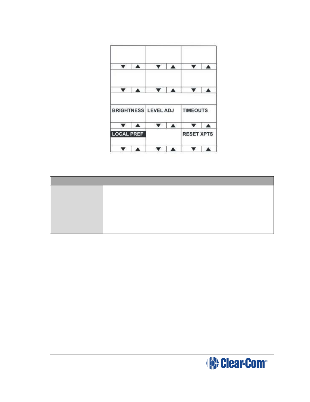
V-Series Panels| User Guide
Page 91
Figure 6-31: Local preferences menu for desktop panels
The LOCAL PREF menu provides access to the following menu items:
Menu option
Description / comments
TIMEOUTS
Displays the timeouts setting menu.
LEVEL ADJ
Displays the menu to set the audio levels for the
microphones, headset and loudspeaker.
BRIGHTNESS
Displays the brightness setup menu that allows the
brightness of all labels and LEDs to be adjusted.
RESET XPTS
Displays the menu for resetting the panel crosspoints to
default level.
Table 22: LOCAL PREF menu options
Note: To return to the main menu, press the Reply key / Reply key talk button
(LOCAL PREF).
6.6.1 TIMEOUTS menu
The LOCAL PREF > TIMEOUTS menu displays the Answerback and Listen
Again timeout settings.
The Answerback timeout controls the length of time an unanswered call
remains in the Reply key stack. If the value is set to OFF (0 seconds) or the
function is disabled, calls will remain in the Reply key stack until actioned.
The Listen Again timeout controls the length of time before recorded
messages are auto deleted and may be set to a value of 0 t- 99 minutes in
units of 1 minute.
Note: If the timeout is set to 99 the messages are not auto-deleted. If the timeout
is set to 0 the Listen Again facility is disabled, so no audio is recorded. You can
Page 92

V-Series Panels| User Guide
Page 92
use this timeout to ensure that recorded conversations are not left on a panel
where they may be accessed later by other operators.
Figure 6-32: Timeouts menu for rack mounted panels
Figure 6-33: Timeouts menu for desktop panels
The TIMEOUTS menu provides access to the following menu items:
Menu option
Description / comments
ANSWERBACK
Enables you to set the panel answerback timeout. Values
range from 0 (OFF) to 60 seconds in 10 second steps.
DISABLE
Disables Answerback timeout.
MSG A DEL
Enables you to set the Listen Again timeout. Values range
from 0 to 99 minutes. If the timeout is set to 0 the Listen
Again facility is disabled (no audio recorded). If the
timeout is set to 99 the messages are not auto-deleted.
Figure 6-34: TIMEOUTS menu options
Note: To return to the LOCAL PREF menu, press the Reply key / Reply key talk
button (TIMEOUTS).
Page 93

V-Series Panels| User Guide
Page 93
6.6.2 LEVEL ADJ (Level Adjust) Menu
The LEVEL ADJ (Level Adjust) menu displays the audio levels setup menu.
Figure 6-35: Level adjust menu for rack mounted panels
Figure 6-36: Level adjust menu for desktop panels
This menu adjusts the audio gain values for gooseneck panel microphone and
headset microphones to preset levels of 20, 40, 50, 60, 70 or 80 db. The
sidetone levels can be set for the first headset (front panel connector) and the
second headset (auxiliary audio connector).
Adjust the gain values and sidetone levels using the up / down buttons or the
rotary control.
Note: If you change these parameters locally, the EHX software can only change It
by performing a black reset. Otherwise, the EXH software can download
changes without a black reset.
Menu option
Description / comments
GN MIC
Gooseneck microphone gain.
HS MIC
First headset microphone gain.
HS2MIC
Second headset microphone gain.
Page 94

V-Series Panels| User Guide
Page 94
Menu option
Description / comments
LS DIM
The amount the loudspeaker is dimmed by when a talk
key is pressed (-70dB, -20dB, -12dB, -6dB, -3dB, 0dB).
L SIDETONE
First headset left sidetone level. The key status (lever key)
or pushbutton or talk button (rotary) is lit red when the
left sidetone is on.
To toggle left sidetone between ON and OFF press the
pushbutton or press the lever key down or press the talk
button (rotary). The default sidetone level is -9dB, the
minimum level is -15.5dB.
R SIDETONE
First headset right sidetone level. The key status (lever
key) or pushbutton or talk button (rotary) is illuminated
red when the right sidetone is on.
To toggle right sidetone between ON and OFF press the
key pushbutton or press the lever key down or press the
talk button (rotary). The default sidetone level is -9dB,
the minimum level is -15.5dB.
L2SIDETONE
Second headset left sidetone level. The key status (lever
key) or pushbutton or talk button (rotary) is illuminated
red when the left sidetone for the second headset is on.
To toggle left sidetone between ON and OFF press the key
pushbutton or press the lever key down or press the talk
button (rotary). The default sidetone level is -9dB, the
minimum level is -15.5dB.
R2SIDETONE
Second headset right sidetone level. The key status (lever
key) or pushbutton or talk button (rotary) is illuminated
red when the right sidetone for the second headset is on.
To toggle right sidetone between ON and OFF press the
key pushbutton or press the lever key down or press the
talk button (rotary). The default sidetone level is -9dB, the
minimum level is -15.5dB.
Table 23: LEVEL ADJ menu options
Note: When a monaural headset is used only the headset left sidetone adjust
operates. The right sidetone adjust has no effect.
Note: To return to the LOCAL PREF menu, press the Reply key / Reply key talk
button (LEVELADJ).
6.6.3 BRIGHTNESS menu
The BRIGHTNESS menu enables you adjust the brightness settings for the
panel.
Page 95

V-Series Panels| User Guide
Page 95
Figure 6-37: Brightness menu for rack mounted panels
Figure 6-38: Brightness menu for desktop panels
Use the up/down buttons or rotary control on the Reply key to alter the
brightness of the displays.
Note: If you change the display brightness locally, the EHX software can only change
it by performing a black reset. Otherwise, the EXH software can download
changes without a black reset.
The displays automatically dim after the time limit set in ECS / EHX Panel
Options (from 0 to 60 minutes) where 0 minutes sets the panel display to dim
mode permanently.
After a further period the display will change to provide a screensaver to
increase the lifetime of the displays.
Note: To return to the LOCAL PREF menu, press the Reply key / Reply key talk
button (BRIGHTNESS).
6.6.4 MESSAGE menu
Use the MESSAGE menu to enable outgoing messages to be recorded,
reviewed, output to audio and erased.
Page 96

V-Series Panels| User Guide
Page 96
Figure 6-39: Message menu for rack mounted panels
Figure 6-40: Message menu for desktop panels
The MESSAGE menu provides access to the following menu options / actions:
Menu options /
actions
Description / comments
RECORD
When you press the RECORD button, you can record up to
10 seconds of audio from the microphone into an audio
file on the panel.
Text inverts while the button is pressed.
REVIEW
When you press the REVIEW button, the outgoing
message is played to the currently selected output device
(Headset or Loudspeaker).
Text inverts while the button is pressed.
PLAY
When you press the PLAY button, the outgoing message is
output to the route configured by ECS / EHX. This will
normally be Matrix 1 or Matrix 2 but may be the EXT1 or
EXT2 output.
Text inverts while the button is pressed.
Page 97

V-Series Panels| User Guide
Page 97
ERASE
When you press the ERASE button, the current outgoing
message is erased.
Configurable
Messaging
Enables access to the Messaging menu on v-series panels.
If the tick box is disabled, the panel will not show the
MESSAGE menu.
If the option is enabled, the panel is in the messaging
menu and the PLAY button is on:
1. Panels with a listen to this panel will hear the recorded
audio.
2. Another panel talking to this panel will also get a listen
route and will be able to hear the recorded message. Note
that only a maximum of 10 panels simultaneously talking
to that panel will hear the recorded message if the PLAY
button is on.
Figure 6-41: MESSAGE menu options
Note: To return to the LOCAL PREF menu, press the Reply key / Reply key talk
button (MESSAGE).
Note: You can use the recorded output message to verify audio paths between ports.
Select a talk path set up on the panel, then enter the MESSAGE menu and
press PLAY. If the talk path connects to another panel, the message is heard
as an incoming talk on the target panel.
6.6.5 RESET XPTS (Reset Crosspoints) menu
The RESET XPTS menu enables you to reset the panel crosspoints to their
default levels.
Press the YES key or pushbutton or talk button to reset the panel crosspoint
levels to their default settings or the NO key to cancel the operation and return
the user to the local preferences (LOCAL PREF) menu.
Note: To return to the LOCAL PREF menu, press the Reply key / Reply key talk
button (RESET XPTS).
6.7 SYS CONFIG (System Configuration) menu
The SYS CONFIG (System Configuration) menu comprises menu options that
enable local panel configuration, input levels adjustment and output levels
adjustment.
Note: If the PIN code has been enabled in ECS / EHX, you must enter a PIN code
entry before you can access this menu.
On lever key or pushbutton panels, enter the PIN code using the volume
up/down buttons under each number. On rotary panels press the rotary
encoder to select the left hand digit and the talk button to select the right hand
Page 98

V-Series Panels| User Guide
Page 98
digit in the display. The PIN code digits will be shown as * in the PIN code
entry window.
Figure 6-42: System configuration menu on rack mounted panels
Figure 6-43: System configuration menu for desktop panels
The SYS CONFIG menu displays the following menu options:
Menu options
Description / comments
PARTY LINE
Displays the partyline configuration menu (PL CONFIG on
the Reply key). Enables interfaces and panels to be
assigned to a partyline.
FIXED GRP
Displays the Fixed Group configuration menu (FG CONFIG
on the Reply key). Enables interfaces and panels to be
assigned to a Fixed Group.
LOCAL PNL
Displays the local panel’s configuration menu.
REMOTE PNL
Displays the remote panel’s configuration menu.
FORCE LSTN
Displays the Forced Listen configuration menu. Enables
sources and destinations configured as keys on the current
panel to be set as forced listens.
Page 99

V-Series Panels| User Guide
Page 99
Menu options
Description / comments
INPUT LVLS
Enables you to set input audio levels.
OUTPUT LVLS
Enables you to set output audio levels.
Table 24: SYS CONFIG menu options
Note: To return to the main menu, press the Reply key / Reply key talk button
(SYS CONFIG).
6.7.1 PARTY LINE configuration menu
The SYS CONFIG > PARTY LINE menu (PL CONFIG on the Reply key)
enables you to configure partylines 1 - 10 by adding panels and interfaces to
the partylines as members.
Figure 6-44: Partyline configuration menu for rack mounted panels
Figure 6-45: Partyline configuration menu for desktop panels
Use the up/down volume buttons (lever key or pushbutton panels) or rotary
control on the Reply Key (PL CONFIG) will scroll through the available
partylines on the panel display.
Page 100

V-Series Panels| User Guide
Page 100
Selecting one of the partylines displays the membership menu for that
partyline.
Note: To return to the SYS CONFIG menu, press the Reply key / Reply key talk
button (PL CONFIG).
6.7.1.1 PL MEMBERS (Partyline membership) menu
The PL CONFIG > PL MEMBERS (Partyline membership) menu enables you
to add / remove interfaces and panels to / from a partyline.
Figure 6-46: Partyline membership menu for rack mounted panels
Figure 6-47: Partyline membership menu for desktop panels
Select INTERFACES to list the interfaces that may be members of the
partyline. Select PANELS to list the panels that may be members of the
partyline.
Note: To return to the PARTY LINE (PL CONFIG) menu, press the Reply key /
Reply key talk button (PL MEMBERS).
 Loading...