

Page 1

PRODUCT INFORMATION
AND APPLICATIONS
2017-18
Page 2

with
Why invest in a product that you’ll have to refinish in a few years?
Protect your investment with Eclipse Shutters! Our technological
advancements have combined the durability homeowners desire
with the look of wood to achieve the ultimate window treatment:
™
Eclipse Shutters with UltraSatin
finish.
Eclipse Shutters with UltraSatin finish will add sophistication and elegance to your windows. They will last for many years with minimal
care. These reasons are why Eclipse Shutters have been the number
one selling plantation shutter in North America for over 20 years.
Page 3

CONTENTS
SELLING
A
The History of Shutters A1
Features & Benefits A2-3
GREENGUARD
25-Year Warranty A6-7
Shutter Panel Parts A8
UltraClearview Mechanism A9
Louver and Divider Rail Sizes A10
Frame Sizes and Applications A11-13
Shutter Accessories A14-16
PANEL CONFIGURATIONS AND HINGING
B
Single Panel Shutters B1-2
Two Panel Shutters B3-6
Three Panel Shutters B7-10
Four Panel Shutters B11-16
Six Panel Shutters B17-20
Patio Doors B21
Bay Windows B22-23
Bow Windows B24
Café Style B25
®
Certification A4-5
OPERATING AND DEPTH CLEARANCE
C
Clearance Charts C1-13
DESIGNING THE RIGHT SHUTTER
D
Helpful Hints D1
Shutters with Uneven Panel Widths D2
Importance of Height Consistency D3
Locating Divider Rails D4
Double Hung Shutters D5
MEASURING GUIDE
E
Inside Mount E1
Outside Mount E2
Bay Windows E3-10
Bow Windows E11-15
Patio Doors E16-17
Corner Windows E18-19
FRENCH DOOR SHUTTERS
French Door Cutout Diagram F1
F
French Door Cutout Configurations F2
French Door Cutout Clearance Charts F3-9
French Door Cutout Measuring Instructions F10
French Door Cutout Installation Instructions F11
French Door with No Cutout Configurations F12
French Door with Catch Receivers Clearance Charts F13-14
French Door Catch Receiver Measuring Instructions F15
French Door Hinged Shutter Measuring Instructions F16
French Door with No Cutout Installation Instructions F17
Ordering Instructions F18-19
Page 4

STANDARD AND OPEN
G
BY-PASS TRACK SYSTEM
By-Pass System Diagrams G1-2
Two Panel By-Pass G3
Three and Four Panel By-Pass G4-5
Six and Eight Panel By-Pass G6
By-Pass Measuring Instructions G7
By-Pass Installation Instructions G8-15
Track System Ordering Instructions G16-17
H
TRIPLE BY-PASS TRACK SYSTEM
Triple By-Pass Track System Diagram H1
Three and Four Panel By-Pass H2
Five Panel By-Pass H3
Six Panel By-Pass H4
Seven Panel By-Pass H5
Eight Panel By-Pass H6
Triple By-Pass Measuring Instructions H7
Triple By-Pass Installation Instructions H8-13
Track System Ordering Instructions H14-15
BI-FOLD TRACK SYSTEM
I
Bi-Fold Track System Diagram I1
Two Panel Bi-Fold I2
Four Panel Bi-Fold I3
Six Panel Bi-Fold I4
Eight Panel Bi-Fold I5
Bi-Fold Measuring Instructions I6
Bi-Fold Installation Instructions I7-11
Track System Ordering Instructions I12-13
TRACK SYSTEM VALANCES
J
Valance Diagram J1
Valance Options J2
Valance Installation J3-4
Valance Return Options J5-7
SPECIALTY SHAPES
K
Features & Benefits K1-2
Shapes & Specifications K3-13
Vertical Supports K14-16
Measuring K17-19
Ordering K20-22
Creating a Template K23-24
Installation K25-27
Page 5

ORDERING PROCEDURE
L
Filling Out the Order Form L1
Filling Out a Regular Order Form L2-4
Filling Out a Bay Order Form L5
Filling Out a Bow Order Form L6
Sample Regular Order Form L7-8
INSTALLATION
M
Tools Required M1
Inside Mount with No Frame M2
Panel Lock Ramp Installation M3
Magnetic Catch Placement M4
Catch Receiver Installation M5
Frame Assembly for 3 or 4 Sided Frames M6
T-Posts M7-9
Inside Mount with L-Frame M10
Inside Mount with Z, Trim, BZ or Deluxe Trim Frames M11
Inside Mount/Outside Mount with Mounting Strip M12
Outside Mount with Casing Frame M13
Outside Mount with L-Frame M14
Bay Window Compound Miter M15
Bow Window Compound Miter M16
GENERAL INFORMATION &
N
TROUBLESHOOTING
Shutter Panel Parts Diagram N1
Two Part Hinges N2
Panels Won’t Stay Closed N3-4
Panels Too Tight N5
Louvers Too Tight N6
Louvers Warped N7
Louvers Need More Tension N8
Panels Sagging N9
Louvers Are Not Operating Properly N10-11
Louvers Discoloring N12
Product is Scratched N12
Page 6

Page 7

A
SELLING
The History of Shutters A1
Features & Benefits A2-3
GREENGUARD
25 Year Warranty A6-7
Shutter Panel Parts A8
Clearview Mechanism A9
Louver & Divider Rail Sizes A10
Frame Sizes and Applications A11-13
Shutter Accessories A14-16
®
Certification A4-5
Page 8
Page 9

Shutters have had a long history of
protecting windows on the outside,
but they were originally designed for
the inside of a home.
On Tudor (1485–1547) and Elizabethan
(1558–1603) homes, shutters were made of solid
boards and covered only the lower half of the
window openings, where no glass was installed
(glass was expensive in those days.) When open,
fresh air came into the room and the shutters folded
back to look like decorative wall panels. When
closed, usually with a bar across, light still came
through the glazed upper half of the window. By
the late seventeenth century, double-hung windows
were popular. Shutters were still attached inside and
decorative, but they covered the whole window.
During the Victorian period (1837–1901) when
more houses were constructed from wood, shutters
moved outdoors. The former stone and brick homes
had such deeply recessed windows that exterior
shutters would have been difficult to reach from
inside, but wooden walls could be built much
thinner and exterior shutters could now be accessed
easily from the inside.
By the late nineteenth century, shutters were
used as much for decoration as for their practical
functions of shelter and protection for the glass.
When mechanization entered Victorian millworks,
shutters became more sophisticated. They were
often louvered or made of narrow horizontal slats
angled to deflect the rain, allow some daylight
through and provide adequate ventilation.
The History of Shutters
In the 1980s, window technology and window
covering choices eliminated the functional use of
outside shutters. However, the revival of Victorian-style
housing and the interest in rehabilitating century-old
homes are bringing shutters back into the limelight
as an interior window treatment. They are often
made from wood, with all its inherent problems of
chipping, warping, shrinking and peeling.
Eclipse
They offer the traditional look of California or
Plantation style shutters without the inherent problems
of wood. Warping, shrinking, chipping, peeling,
and color fading are things of the past with
Eclipse
Eclipse
and door fitting. They are shipped complete with all
frames and hardware ready for mounting. They are
available in three colors: Cotton, Pearl and Vanilla.
Do not be fooled by the competition. There is only
one Eclipse
®
Shutters are an extremely durable shutter.
®
Shutters.
®
Shutters offer complete custom window
®
Shutter!
A1
Page 10

Traditional Look
The look and quality your customers demand but at the
cost and durability of Polyresin 3
®
.
Features & Benefits
Low Maintenance
®
The Polyresin 3
Eclipse® Shutter is easy to clean with just
soap and water.
Environmentally Friendly
Eclipse
®
Shutters do not destroy our forests. All scrap is
recycled.
Made from Polyresin 3
®
A colorfast compound with UV stabilizers designed with
strength and durability, yet retaining a special warmth
and feel. Shutters will not warp, shrink, chip, peel, or
fade and never need painting.
Fire Retardant
®
Polyresin 3
is fire retardant and self-extinguishing. It is
safe to use in residential and commercial applications.
Meets (NFPA701) National Fire Code Standards.
Waterproof
Ideally suited for use above kitchen sinks, bathrooms
or other high humidity areas. Eclipse
®
Shutters have no
unsightly staples which may rust, and will not warp or
crack due to water exposure.
A2
Additional Insulator
An R-value of 3.40 helps to reduce heating and air costs
and outside noise. Closing the louvers upward can help
keep heat in the home and provide more privacy.
Modern Manufacturing
Custom crafted in state-of-the-art computerized production
facilities that meet today’s demanding quality standards.
Fast Production Time
7-day production guaranteed.
Colors
Cotton, Pearl and Vanilla
Best for Kids™ Certified
This third party certification program specifies
criteria to identify window covering products
that are best suited for use in homes or in facilities
in which young children are expected to be present.
Page 11

Features & Benefits
Elliptical Louver Sizes
2 1/2”, 3 1/2”, and 4 1/2”
Patented Tilt Bar Connecting Method
Provides the time honored look associated with shutters.
Louvers can be opened or closed in both directions,
unlike other shutters which are one-directional only. This
method has eliminated unsightly gears or staples which
tend to rust or break.
Patented UltraClearview™
A hidden tilt system located on the rear of each panel.
UltraClearview is attached to the hinge side of the
louvers, resulting in a clean, contemporary look.
Patented Seamless Louver Caps
Innovative seamless capping technology eliminates
the seam between the louver body and the end cap,
for a sleek and modern look.
Panel Lock with Roller
This unique system eliminates the use of magnets. When
panels are closed, a spring-loaded plunger acts as a
ball catch to hold the panels in the closed position.
Aluminum Jamb Inserts
Provides a hidden reinforcement for patio door
shutters and larger shutter panels.
French Door Cutouts
Our French Door Cutout is ideal for adding shutters
to French doors. The Cutout is designed to work with
standard round door handles and lever handles.
Available with all louver sizes.
Pre-drilled Frames
Pre-drilled installation holes are strategically placed
on all frames for accurate, quick, and clean
installation.
Factory Installed Two Part Hinge System
Quick and easy to install. Allows panels to
be removed easily for cleaning. Panels open
fully for total access to the windows.
Light Block and Interlock
®
Exclusive to Eclipse
Shutters, they provide an
insulating seal and cover unwanted light
gaps between panels.
Frame Grooves
The spring loaded roller of the panel lock locates the
integrated groove in all frames. Eliminates the need for
magnets and catch plates.
Exclusive Deluxe Divider Rail
The unique design of this rail integrates a handle which
provides a clean and easy method of opening shutters.
Offered as an option to the existing regular divider rail,
the deluxe divider rail is the ultimate in functionality,
design, and elegance.
Snap and Hold Corner Key and
Notched Frames
Our snap and hold corner key and notched frames were
developed to eliminate the use of glue and provide a
clean, quick and easy installation. All frames, excluding
L-Frame outside mount, with a 45-degree miter are
notched to accept this corner key.
Adjustable Jamb Cap
If adjustments are required, the screw located
on the bottom of each panel can be threaded
in or out of the cap accordingly. Thread into
the panel until the screw is virtually invisible
when adjustments are not needed. (Available only
with magnet applications)
Permanent UltraSatin™ Finish
®
Our Polyresin 3
compound features a permanent
finish resistant to dents and scratches. Should a
scratch occur, it can be removed without harming
the finish.
Warranty
®
Eclipse
Warranty. Note: Eclipse
Shutters are backed with a 25-Year
fabricators reserve the
right to refuse manufacture of out-of-spec or void
warranty product.
A3
Page 12

About the GREENGUARD® Environmental Institute
The GREENGUARD Environmental Institute (GEI) is an industry-independent, non-profit organization that oversees the
GREENGUARD Certification Program. As an ANSI Authorized Standards Developer, GEI establishes acceptable
indoor air standards for indoor products, environments, and buildings. GEI’s mission is to improve public health and
quality of life through programs that improve indoor air. A GEI Advisory Board consisting of independent volunteers,
who are renowned experts in the areas of indoor air quality, public and environmental health, building design and
construction, and public policy, provides guidance and leadership to GEI.
®
About GREENGUARD
Certification
Product certification program for low emitting interior building materials, furnishings, and finish systems. All
GREENGUARD Certified Products have been tested for their chemical emissions performance and can be found in
the GREENGUARD Online Product Guide.
®
About GREENGUARD
Gold (for Children & Schools Certification)
A product certification program for low-emitting interior building materials, furnishings, and finish systems used in
educational, office and other sensitive environments. All GREENGUARD Gold products have been tested for their
chemical emissions performance according to CA 01350 and can be found in the GREENGUARD Online Product
Guide.
GREENGUARD Gold program’s minimum requirements comply with the State of California’s Department of Health
Services Standard Practice (CA Section 01350) for testing chemical emissions from building products used in
schools, offices and other sensitive environments. As such, GREENGUARD Gold products can be used as a strategy
to earn valuable credits in the CHPS Best Practices Manual for K-12 schools, U.S. Green Building Council’s LEED
Green Building Rating System, Green Guide for Healthcare, NAHB Green Building Guidelines, Green Globes,
Regreen and numerous other local green building codes.
Children are more heavily exposed to environmental toxins than adults; as a result their exposure levels are the
basis for sensitive environments. They consume more food, water, and have higher inhalation rates per pound of
body weight than adults. To account for inhalation exposure to young children with greater sensitivities, a body
burden correction factor of 0.43 has been applied to current allowable emission levels from indoor materials and
furnishings.
Emission controls are established to define low-emitting materials for environments where people spend extended
periods of time and have children and sensitive adults in residence. These may include schools, daycares,
healthcare facilities and residential and commercial spaces.
See the following page for the Greenguard Certificates for Eclipse Shutters. For more information about Greenguard,
please visit their website at www.greenguard.org.
Eclipse
®
Shutters and GREENGUARD
®
Eclipse Shutters has been tested and vertified for both GREENGUARD Indoor Air Quality and GREENGUARD
Gold. See page A5 for the GREENGUARD Gold Certificate issued to Eclipse Shutters. In addition, GREENGUARD
has listed Eclipse Shutters on their website as being resistant to the growth of mold. For more information about
GREENGUARD, please visit their website at www.greenguard.org.
A4
Page 13

A5
Page 14

25 YEAR WARRANTY
Shutters are warranteed by
ECLIPSE® SHUTTERS
The Manufacturer
To: The Original Owner
Purchased at:
Installed by: Name of Installation Company Date Installed:
Eclipse Shutters are intended for interior use only. See reverse for terms and conditions contained in this 25 Year Warranty.
Name of Retailer/Dealer
Purchaser’s Name
Purchaser’s Address
Date Purchased:
25 YEAR WARRANTY REGISTRATION CERTIFICATE
Purchaser’s Name
Purchasers’ Address
Purchased at: Name of Retailer/Dealer Date Purchased:
Installed by: Name of Installation Company Date Installed:
Page 15

25 YEAR WARRANTY
Warranty on Shutter Frame
and Shutter Panel
Shutters are warranted against such defects in material that
might result in blistering, peeling, flaking, corroding, and
fading of the shutter frame or panel members for a period
of twenty-five (25) years from the date of installation.
This Warranty on the Polyresin3
panels shall remain in effect only if normal cleaning
practices are followed periodically (see section
“Maintenance and Cleaning”).
®
frame and Polyresin3®
5 Year Warranty on Hardware
Eclipse® warrants that the hardware will remain in good
operational condition for a period of five (5) years from the
date of installation.
General Conditions
This Warranty must be validated by having the Registration
Certificate completed by the installer and the original
purchaser and received by Eclipse
than thirty (30) days after the completed installation. This
will ensure the property owner is entitled to this 25 Year
Warranty.
The Warranty stipulated in this document is the only
warranty applicable to Eclipse® Shutters and is granted in
lieu of any warranties otherwise implied by law or equity
and no such warranties shall apply to Eclipse® Shutters 25
Year Warranty.
®
Shutters no later
1. Product Use
This Warranty applies only in respect to products used
strictly for the purpose for which they were intended. Eclipse
Shutters are intended for internal use only.
2. Warranty Limitations
Eclipse® Shutters liability is limited solely and exclusively to
repair or replacement, at the option of Eclipse® and under
no circumstances will Eclipse® be liable for incidental or
consequential charges such as, but not limited to, labor
costs for any purpose, inconvenience, damage or injury to
persons or to property, or any other expense.
3. Replacement Parts or Repairs
Eclipse® reserves the right to discontinue or change any
Eclipse® shutter as currently manufactured. If an exact
replacement part is not available, Eclipse® reserves the right
to substitute parts of equal quality at its sole option.
Exclusions from Warranty Coverage
The following are excluded from coverage
under this Warranty:
a. Exposure to air pollutants and normal atmospheric
conditions may cause all Polyresin3
gradually suffer an accumulation of surface dirt or
stains. These are normal occurrences and are not
covered under the Eclipse
b. Any defect, malfunction, or failure to perform which has
occurred because of unreasonable use, improper
application, or failure to perform reasonable or
necessary maintenance.
c. Any damage to the shutters or components of the
shutters caused by settlement or structural defects of the
building in which they are installed.
d.
Any damage caused by wind, hail, lightning, or other
acts of God, intentional acts, accidents, negligence, or
exposure to harmful chemicals or pollutants.
Damage caused by improper handling or installation.
e.
f. Any shutter which has been repaired or modified or
attempted to have been repaired or modified by any
person other than a duly authorized representative of
Eclipse® Shutters.
g. Shutters are light controlling but not black out.
h. Shutters made without divider rails, too wide, too high,
or over the maximum square footage are not warranted.
®
Warranty.
®
surfaces to
Effective Date of Warranty
This Warranty will take effect from the date the installation
of the shutters has been completed at the premises
identified in the warranty certificate. The registration
certificate must be submitted to Eclipse
(30) days from the date of installation.
®
no later than thirty
Maintenance and Cleaning
Polyresin3® materials are closer to “maintenance free” than
any other building material.However, surfaces may become
dirty. Normal maintenance requires washing with mild soap
and water using a soft cloth. For difficult to remove dirt
and stains, water-based household cleaners can be used.
Chlorine-based cleaners or other cleaners containing organic
solvents could affect the surface appearance and durability
of the product.
Procedure and Conditions of Warranty
Remedy
Repairs are done at the Eclipse® plant. Shutters must be
brought to Eclipse® or an Eclipse® fabricator.
Eclipse® will not be responsible for any costs incurred in
transporting shutters to and from the Eclipse™ plant.
In the event that the Eclipse® obligation under this Warranty
is sought, the Owner must notify the Dealer/ Distributor
in writing within thirty (30) days after the defect has first
appeared. Such notification must contain the following:
a. Name and address of the Owner.
b. Date of installation.
c. A brief description of the defect.
Upon receipt of this information, the Dealer/Distributor will
notify the Owner of his share of prorated costs (where such is
applicable), in accordance with the Proration Schedule.
The Dealer/Distributor will provide repair or replacement
parts to the owner only upon receipt of payment of the
Owner’s share of the prorated costs.
PLEASE ENCLOSE IN AN ENVELOPE AND MAIL TO:
1327 Northbrook Parkway, Suite 410
Suwanee, GA 30024
A7
Page 16
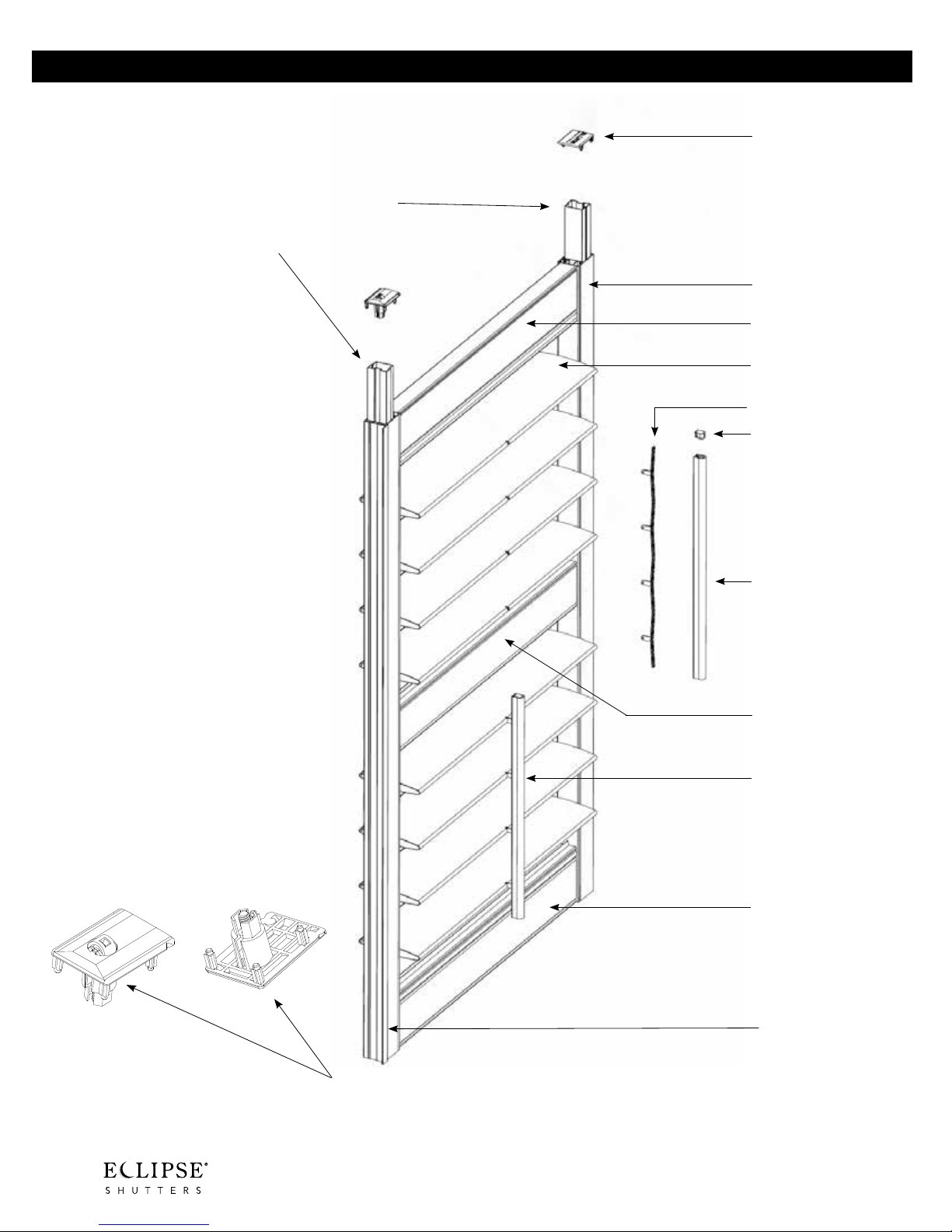
Shutter Panel Parts
Vertical Jamb (Stile) Cap
Aluminum Jamb Inserts
for added support and
strength
Vertical Jamb (Stile)
Top Rail
Louver
Tilt Bar
Connectors
Tilt Bar Cap
Tilt Bar
Divider Rail
Tilt Bar Attached
Bottom Rail
Interlock
A8
Panel Lock Jamb Cap
Page 17
UltraClearview
Connector
UltraClearview™ Mechanism
Elliptical Louver
Louver End Cap
UltraClearview
Bar
Aluminum Inserts for Louvers
add strength when required
UltraClearview is located on back of panel on the hinge side.
UltraClearview adds an additional protection to the back of the louvers.
A9
Page 18
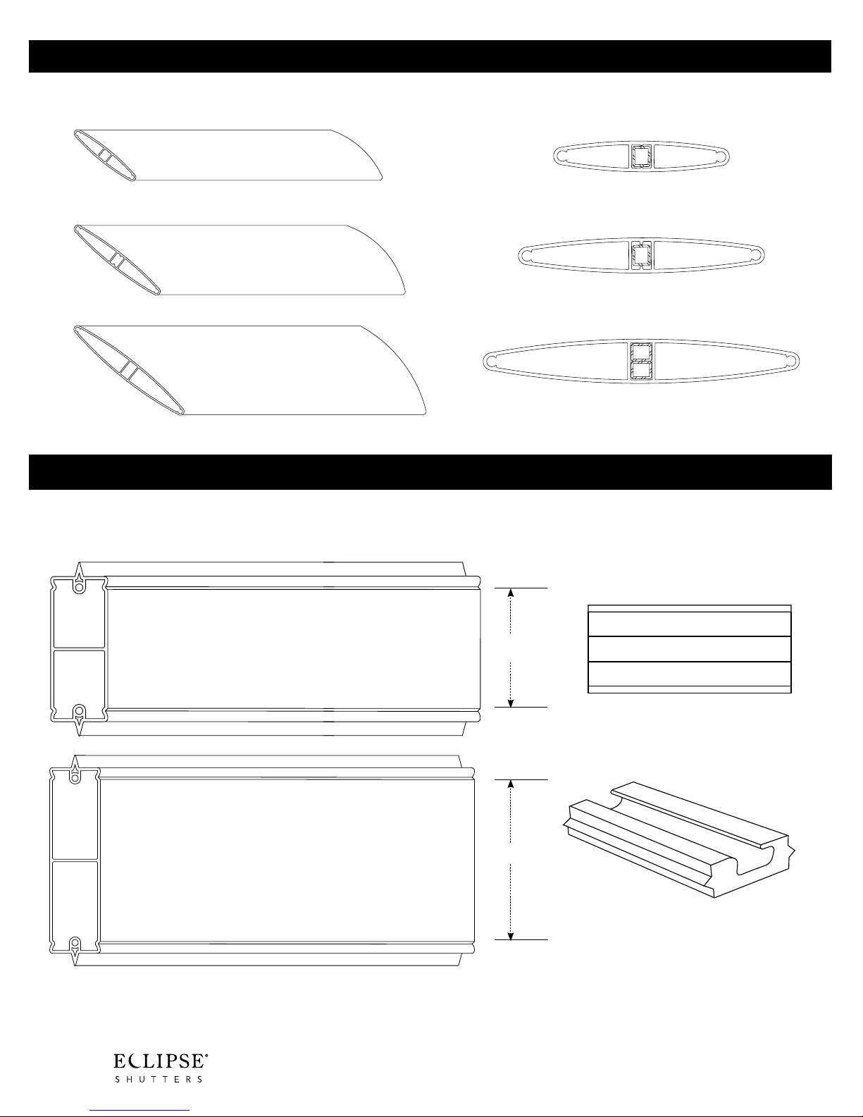
Louver Sizes
2 1/2”
2 1/2” Louver
Reinforcement added at 20”
3 1/2”
4 1/2”
Divider Rail Sizes
Used to divide top louvers from bottom louvers within the same panel
Regular Deluxe
Divider Rail for
3 1/2” Louver (replaces 1 louver)
3 1/2” Louver
Reinforcement added at 19”
4 1/2” Louver
Reinforcement added at 22”
2 5/8”
Divider Rail for
2 1/2” Louver (replaces 2 louvers)
and 4 1/2” Louver (replaces 1 louver)
Note: Divider rail must be used on panels 60” and longer. Two Divider Rails
must be used on panels 90” and longer, with less than 50” between rails.
Divider rails are required on bi-folds at 50”.
A10
3 3/4”
The exclusive Deluxe Divider
Rail provides a clean and easy
method of opening shutters.
This Deluxe Divider Rail with the
built-in handle is an option to
the regular divider rail.
Page 19
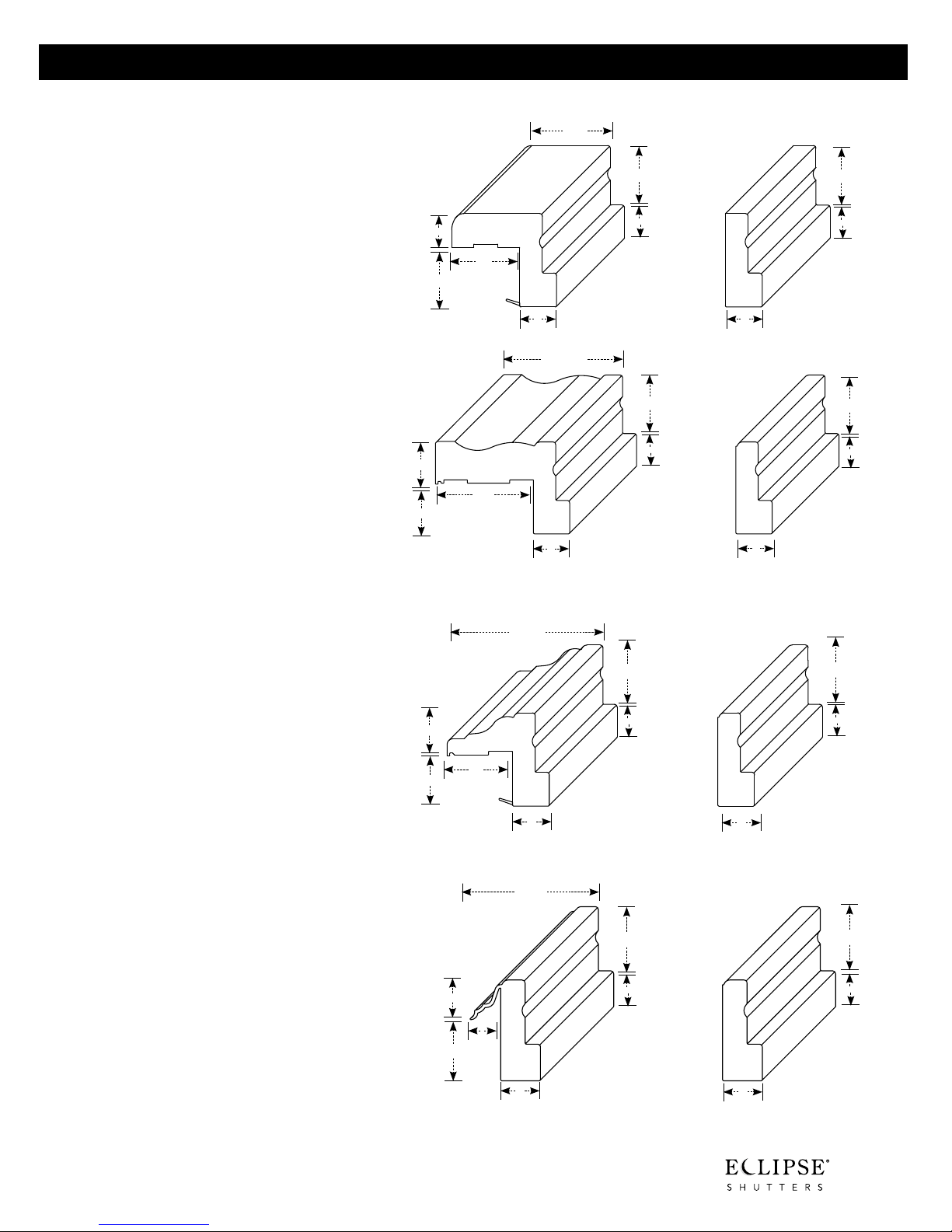
Frame Sizes and Applications
Bullnose Z Frame with Flex
(BZ Frame) & Sill
Used for inside mounts in openings with drywall
returns and without trim and includes a 3/8”
standard IM deduction. May be ordered with Sill
Frame at bottom for openings with a window sill.
Because the extended leg has been removed,
the bottom frame will sit flat on window sill. The
Sill Frame will be positioned at the bottom unless
otherwise specified
Deluxe Trim Frame
(D Frame) & Sill
Used for inside mounts in openings with drywall
returns and without trim and includes a 1/4”
standard IM deduction. May be ordered with Sill
Frame at bottom for openings with window sill.
Because the extended leg has been removed, the
bottom frame will sit flat on the window sill. The
Sill Frame with be positioned at the bottom unless
otherwise specified.
15
⁄16”
11⁄8”
2”
5
1
⁄16”
3
3
⁄4”
1
1
1
⁄8”
1
⁄2”
7
⁄8”
⁄4“
1
⁄2”
7
⁄8”
5
⁄16”
1
3
⁄4“
211⁄16”
15⁄16”
3
⁄4“
1
1
⁄2”
⁄2”
15⁄16”
3
⁄4“
23⁄16”
7
⁄8”
7
⁄8”
Trim Frame with Flex
(T Frame) & Sill
Used for inside mounts in openings with drywall
returns and without trim and includes a 3/8”
standard IM deduction. May be ordered with Sill
Frame at bottom for openings with a window sill.
Because the extended leg has been removed,
the bottom frame will sit flat on window sill. The
Sill Frame will be positioned at the bottom unless
otherwise specified.
Z-Frame & Sill
Used for inside mount applications only. Blends well
with all types of trim and includes a 1/4” standard
IM deduction. Excellent for slightly out of square
windows because the extended leg covers many
imperfections. Jamb depth required is a minimal 1
1/4”. May be ordered with Sill Frame at the bottom
for openings with a window sill. Because extended
leg has been removed, the bottom frame will sit flat
on a window sill. The Sill Frame will be positioned
at the bottom unless otherwise specified
15
⁄16”
11⁄8”
13
⁄16”
11⁄4”
17⁄16”
5
115⁄16”
15⁄16”
3
⁄4“
1
⁄2”
7
⁄8”
1
⁄2”
7
⁄8”
15⁄16”
3
⁄4“
11⁄8”
15⁄16”
3
⁄4“
1
⁄2”
1
⁄2”
15⁄16”
3
⁄4“
⁄8”
7
⁄8”
7
⁄8”
A11
Page 20

Frame Sizes and Applications
L-Frame
May be used for inside mounts if window openings are
square (a 1/8” IM deduction standard), or outside mounts
directly on top of trim or beside trim. For an inside mount,
on out-of-square openings caulking or the optional L-Frame
Cover Strip may be necessary to cover any uneven gaps.
The optional L-Frame Cover Strip may be ordered on the
Order Form. The Cover Strip is glued to the face of the
L-Frame.
L-Frame with 1/2” extension added
Used for outside mount installations with the 2 1/2” louver.
Usually used when the frame is installed beside the trim or
to clear any obstructions. Additional extensions may be
requested on the Order Form if required.
29⁄16”
21⁄16”
3
⁄4“
3
⁄4“
5
⁄16”
1
3
⁄4“
15⁄16”
3
⁄4“
15⁄16”
1
1
⁄4”
L-Frame with two 1/2” extensions
added
Used for outside mount installations with the 3 1/2” louver.
Usually used when the frame is installed beside the trim
or to clear any obstructions. Additional extensions may be
requested on the Order Form if required.
Note: Casing Sill Frame can be used in place of L-Frame.
The Casing Sill Frame is 3/8” taller, has a decorative
face and accepts the L-Frame extension when additional
projection is needed.
31⁄16”
5
⁄16”
1
3
⁄4“
15⁄16”
3
1
⁄4”
5
⁄16”
1
A12
Page 21
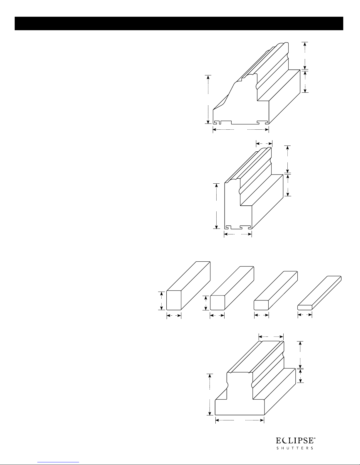
Casing Frame (C-Frame)
Used for outside mount only. Installed on the wall or
directly on top of an existing trim. When installing on
top of an existing trim, an optional C-Frame Cover Strip
may be requested on the Order Form. The C-Frame
Cover Strip covers the gap created between the back
of the frame and the front of the trim. The Cover Strip is
inserted into the C-Frame. The Casing Frame Extension
adds 3/4” projection to the shutter.
Casing Sill Frame
Used in conjunction with the Casing Frame in outside
mount applications, the Sill Frame will sit flat on a window sill. The Sill Frame will be positioned at the bottom
unless otherwise specified. May also be used as a
stand alone frame. Use the casing sill as an alternative
to the L Frame in both inside and outside mount
applications.
2
7
⁄16”
27⁄16”
211⁄16”
15⁄16”
11⁄8”
3
⁄4”
15⁄16”
11⁄8”
Mounting Strip
Used in conjunction with adjustable bent-leaf hinges
for inside mounts without frames or as a light block
mounted on the inside of panels which are installed
without frames. It is not visible from inside the room.
Unless requested otherwise, 3/4” x 3/4” will
1”
be supplied.
T-Post
Used to separate and hinge multiple panels in wide
openings. Usually placed directly in front of any existing
window dividers. It is notched to fit into the frames, or
can be installed to existing opening with L brackets.
15⁄16”
3
⁄4”
3
⁄4”
3
⁄4”
1
⁄2”
3
⁄4”
1
⁄4”
1
1
⁄4”
3
⁄4”
15⁄16”
3
⁄4”
1
⁄16”
2
23⁄8”
A13
Page 22
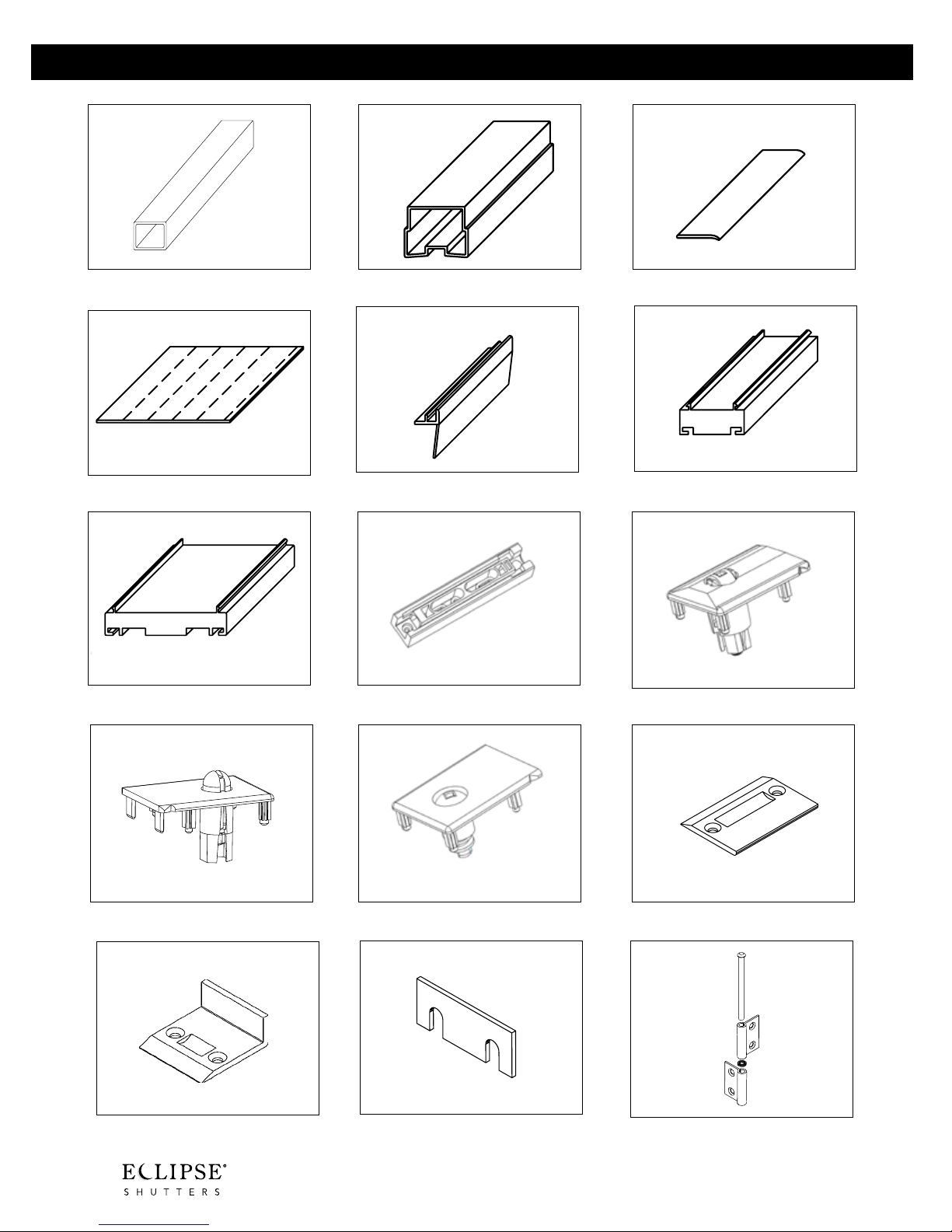
Shutter Accessories
3. L-Frame Cover Strip2. Aluminum Insert for Jambs1. Aluminum Insert for Louvers
4. Scribe
7. Casing Frame Extension
10. Panel Lock Jamb Cap 11. Adjustable Jamb Cap 12. Panel Lock Ramp
5. Casing Frame Cover Strip
8. Molded Insert for Jambs
6. L-Frame Extension
9. Panel Lock Jamb Cap with Roller
13. Panel Lock Ramp with Back
A14
14. Hinge Shims
15. Hinge Bushing
Page 23

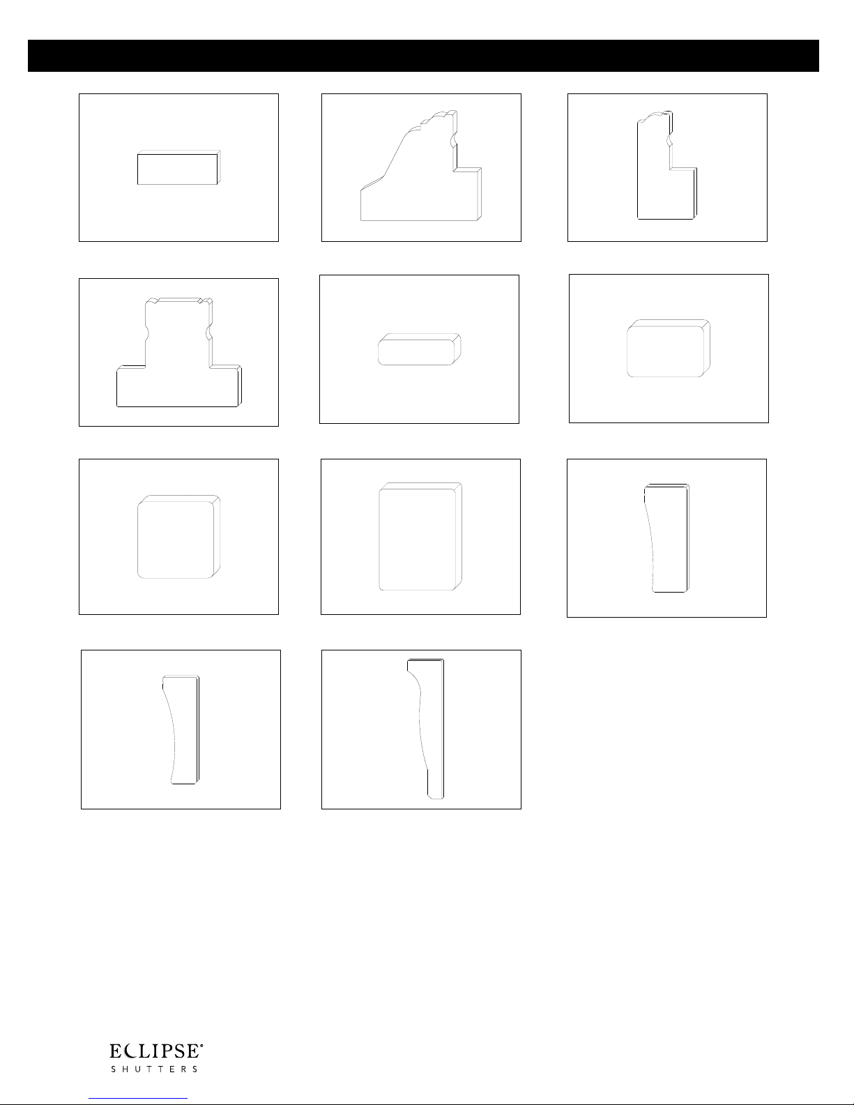
Shutter Accessories
18. Front Tilt Bar Connector17. UltraClearview Connector16. 3/8” Button Plug
19. Louver Tensioner
22. Small Floor Guide
25. Bullnoze Z Sill Cap 26. Deluxe Trim Frame Cap 27. Trim Frame Cap
20. Corner Key
23. Large Floor Guide
21.Valance Bracket
24. Bullnoze Z Frame Cap
28. Sill Trim Frame Cap
29. L Frame Cap
30. L Frame + 3 Extensions Cap
A15
Page 24
Shutter Accessories
33. Casing Sill Frame Cap32. Casing Frame Cap31. L Frame Extension Cap
34. T Post Cap
37. 3/4” x 3/4” Mounting Strip Cap
40. By-pass Valance Cap 41. Crown Valance Cap
35. 1/4” x 3/4” Mounting Strip Cap
38. 1” x 3/4” Mounting Strip Cap
36. 1/2” x 3/4” Mounting Strip Cap
39. Bi-fold Valance Cap
A16
Page 25

®
B
PANEL CONFIGURATIONS
AND HINGING
Single Panel Shutters B1-2
Two Panel Shutters B3-6
Three Panel Shutters B7-10
Four Panel Shutters B11-16
Six Panel Shutters B17-20
Patio Doors B21
Bay Windows B22-23
Bow Windows B24
Café Style B25
Page 26

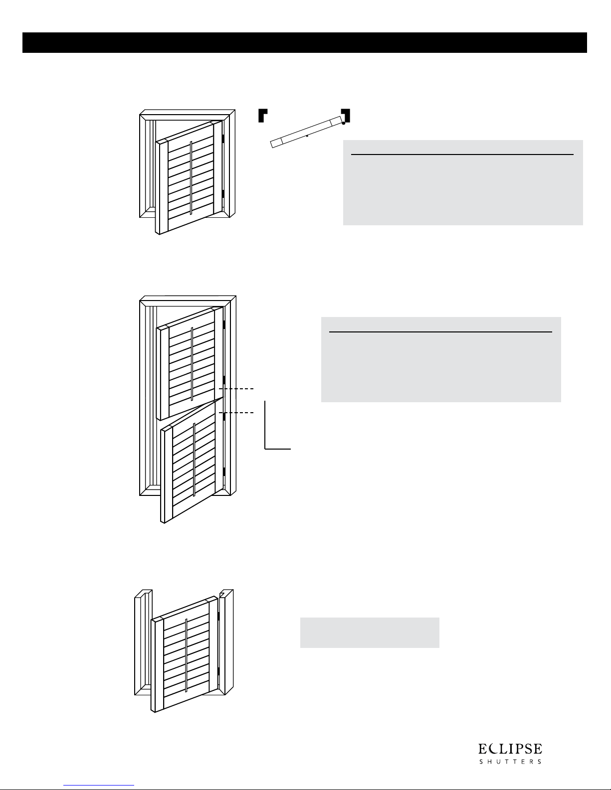
Single Panel Shutters
®
P1-L (left hinge) two, three, or four sided frame
Left Hinge
P1DH-L Double Hung (left hinge) two, three, or four sided frame
2 1/2” 3 1/2” 4 1/2”
• Minimum Width: 6” 6” 6”
• Maximum Width: 30” 30” 30”
• Minimum Height: 32” 32” 32”
• Maximum Height: 120” 120” 120”
• Maximum Square Ft.: 15 15 15
2 1/2” 3 1/2” 4 1/2”
• Minimum Width: 6” 6” 6”
• Maximum Width: 36” 36” 36”
• Minimum Height: 16” 16” 16”
• Maximum Height: 120” 120” 120”
• Maximum Square Ft.: 15 15 15
{
Note: Double Hung styles have a possible 6” to 8” of
obstructed view where bottom rail meets top rail.
Note: A Double Hung (DH) panel is considered
2 panels for pricing purposes.
P1IF-L Inverted three sided frame (café style)
Optional Horizontal T-Post. See D5 for additional details.
• Maximum Square Ft.: 15
Note: If panel height is to be shorter than the frame, then
specify in special instructions, see page B27 for
additional details.
* Void Warranty authorization is required if panels are ordered over the maximum widths, heights, square footage or divider rails not used
B1
when required (see D4). Eclipse® reserves the right to refuse to manufacture out-of-spec, or void warranty product.
Page 27
P1-R (right hinge) two, three, or four sided frame
®
2 1/2” 3 1/2” 4 1/2”
• Minimum Width: 6” 6” 6”
Right Hinge
• Maximum Width: 36” 36” 36”
• Minimum Height: 16” 16” 16”
• Maximum Height: 120” 120” 120”
• Maximum Square Ft.: 15 15 15
P1DH-R Double Hung (right hinge) two, three, or four sided frame
2 1/2” 3 1/2” 4 1/2”
• Minimum Width: 6” 6” 6”
• Maximum Width: 30” 30” 30”
• Minimum Height: 32” 32” 32”
• Maximum Height: 120” 120” 120”
{
• Maximum Square Ft.: 15 15 15
Optional Horizontal T-Post. See D5 for additional details.
Single Panel Shutters
Note: Double Hung styles have a possible 6” to 8” of
obstructed view where bottom rail meets top rail.
Note: A Double Hung (DH) panel is considered
2 panels for pricing purposes.
P1IF-R Inverted three sided frame (café style)
Note: If panel height is to be shorter than the frame, then
specify in special instructions, see page B27 for
additional details.
• Maximum Square Ft.: 15
* Void Warranty authorization is required if panels are ordered over the maximum widths, heights, square footage or divider rails not used
when required (see D4). Eclipse® reserves the right to refuse to manufacture out-of-spec, or void warranty product.
B2
Page 28
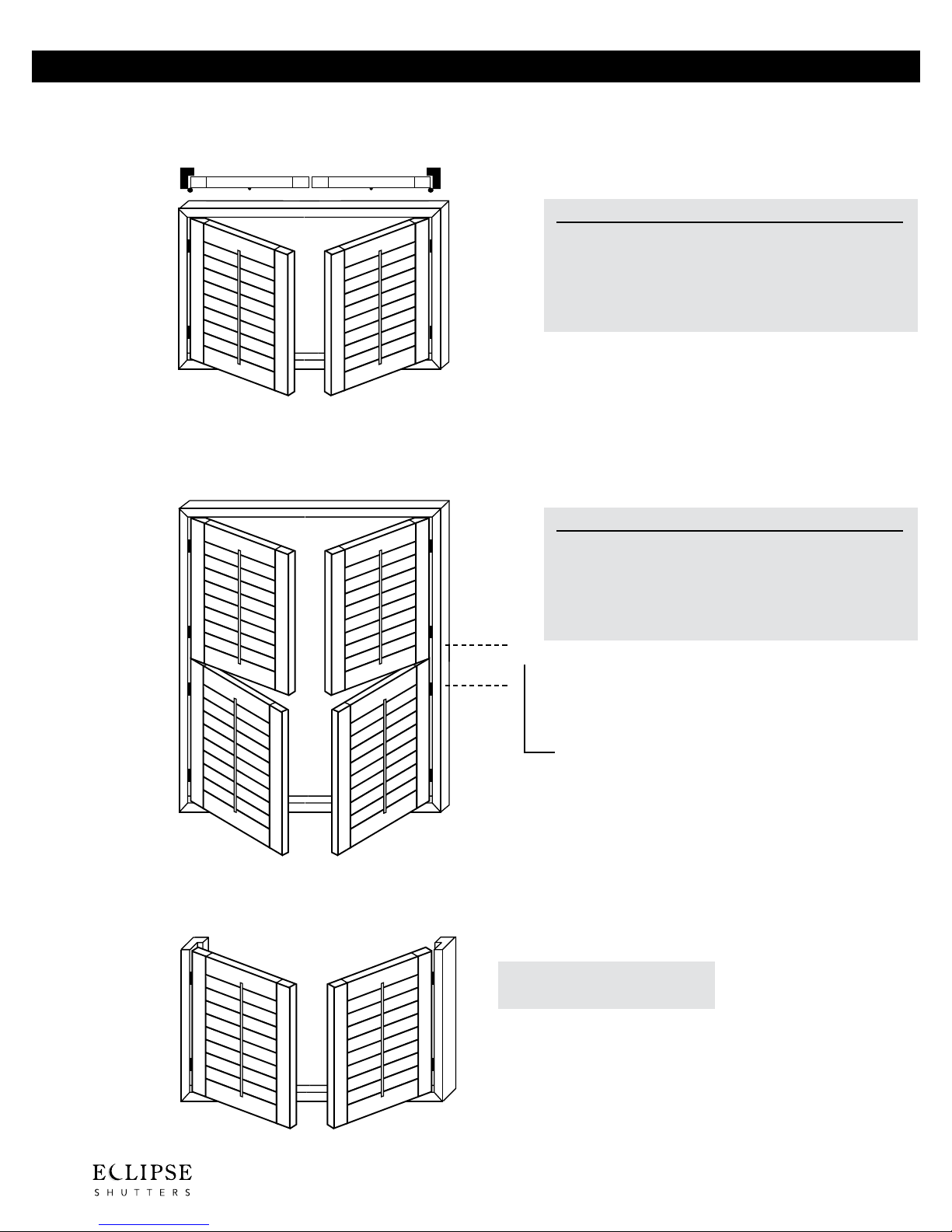
Two Panel Shutters
®
P2-LR two, three, or four sided frame
Left Right
P2DH-LR Double Hung, two, three, or four sided frame
2 1/2” 3 1/2” 4 1/2”
• Minimum Width: 20” 20” 20”
• Maximum Width: 72” 72” 72”
• Minimum Height: 16” 16” 16”
• Maximum Height: 120” 120” 120”
• Maximum Square Ft.: 30 30 30
P2IF-LR Inverted, three sided frame (café style)
2 1/2” 3 1/2” 4 1/2”
• Minimum Width: 20” 20” 20”
• Maximum Width: 60” 60” 60”
• Minimum Height: 32” 32” 32”
• Maximum Height: 120” 120” 120”
• Maximum Square Ft.: 30 30 30
{
Optional Horizontal T-Post. See D5 for additional details.
Note: Double Hung styles have a possible
6” to 8” of obstructed view where
bottom rail meets top rail.
Note: A Double Hung (DH) panel is
considered 2 panels for
pricing purposes.
* Void Warranty authorization is required if panels are ordered over the maximum widths, heights, square footage or divider rails not used
B3
when required (see D4). Eclipse® reserves the right to refuse to manufacture out-of-spec, or void warranty product.
• Maximum Square Ft.: 30
Note: If panel height is to be shorter than the frame, then
specify in special instructions, see page B27 for
additional details.
Page 29
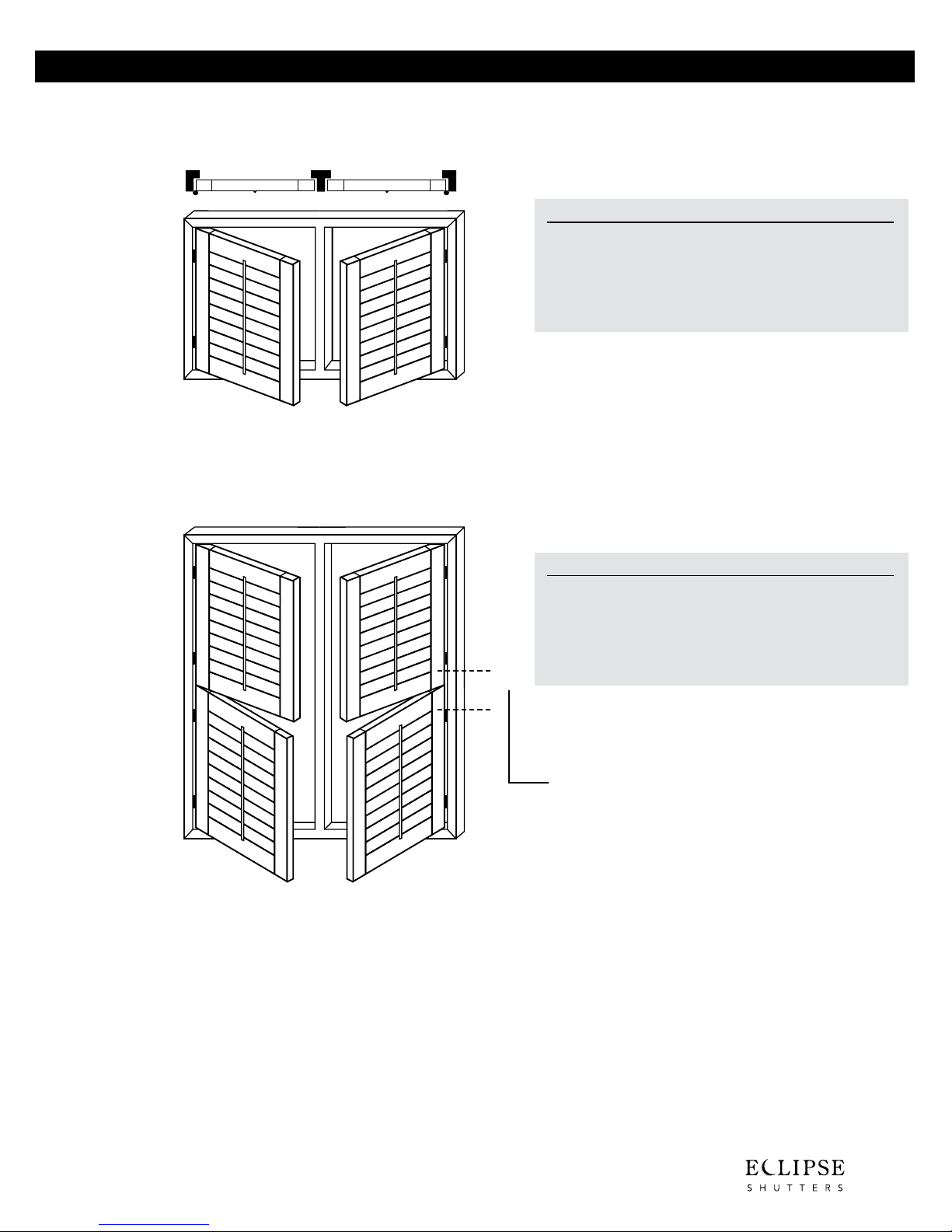
P2-LTR two, three, or four sided frame
®
Left T-post Right
2 1/2” 3 1/2” 4 1/2”
• Minimum Width: 20” 20” 20”
• Maximum Width: 72” 72” 72”
• Minimum Height: 16” 16” 16”
• Maximum Height: 120” 120” 120”
• Maximum Square Ft.: 30 30 30
P2DH-LTR Double Hung, two, three, or four sided frame
Two Panel Shutters
2 1/2” 3 1/2” 4 1/2”
• Minimum Width: 20” 20” 20”
• Maximum Width: 60” 60” 60”
• Minimum Height: 32” 32” 32”
• Maximum Height: 120” 120” 120”
• Maximum Square Ft.: 30 30 30
{
Optional Horizontal T-Post. See D5 for additional details.
Note: Double Hung styles have a possible
6” to 8” of obstructed view where
bottom rail meets top rail.
Note: A Double Hung (DH) panel is
considered 2 panels for
pricing purposes.
* Void Warranty authorization is required if panels are ordered over the maximum widths, heights, square footage or divider rails not used
when required (see D4). Eclipse® reserves the right to refuse to manufacture out-of-spec, or void warranty product.
B4
Page 30
Two Panel Shutters
®
P2-LL Two left bi-fold, two, three, or four sided frame
Left Left
P2DH-LL Double Hung, two, three, or four sided frame
2 1/2” 3 1/2” 4 1/2”
• Minimum Width: 20” 20” 20”
• Maximum Width: 48” 48” 48”
• Minimum Height: 16” 16” 16”
• Maximum Height: 120” 120” 120”
• Maximum Square Ft.: 25 25 25
2 1/2” 3 1/2” 4 1/2”
• Minimum Width: 20” 20” 20”
• Maximum Width: 40” 40” 40”
• Minimum Height: 32” 32” 32”
• Maximum Height: 120” 120” 120”
• Maximum Square Ft.: 20 20 20
{
Optional Horizontal T-Post. See D5 for additional details.
P2IF-LL Inverted, three sided frame (café style)
* Void Warranty authorization is required if panels are ordered over the maximum widths, heights, square footage or divider rails not used
B5
when required (see D4). Eclipse® reserves the right to refuse to manufacture out-of-spec, or void warranty product.
Note: Double Hung styles have a possible
6” to 8” of obstructed view where
bottom rail meets top rail.
Note: A Double Hung (DH) panel is
considered 2 panels for
pricing purposes.
• Maximum Square Ft.: 30
Note: If panel height is to be shorter than the
frame, then specify in special instructions,
see page B27 for additional details.
Page 31

P2-RR Two right bi-fold, two, three, or four sided frame
®
Right Right
2 1/2” 3 1/2” 4 1/2”
• Minimum Width: 20” 20” 20”
• Maximum Width: 48” 48” 48”
• Minimum Height: 16” 16” 16”
• Maximum Height: 120” 120” 120”
• Maximum Square Ft.: 25 25 25
P2DH-RR Double Hung, two, three, or four sided frame
2 1/2” 3 1/2” 4 1/2”
• Minimum Width: 20” 20” 20”
• Maximum Width: 40” 40” 40”
• Minimum Height: 32” 32” 32”
• Maximum Height: 120” 120” 120”
{
• Maximum Square Ft.: 20 20 20
Optional Horizontal T-Post. See D5 for additional details.
Two Panel Shutters
Note: Double Hung styles have a possible
6” to 8” of obstructed view where
bottom rail meets top rail.
Note: A Double Hung (DH) panel is
considered 2 panels for
pricing purposes.
P2IF-RR Inverted, three sided frame (café style)
• Maximum Square Ft.: 30
Note: If panel height is to be shorter than the
frame, then specify in special instructions,
see page B27 for additional details.
* Void Warranty authorization is required if panels are ordered over the maximum widths, heights, square footage or divider rails not used
when required (see D4). Eclipse® reserves the right to refuse to manufacture out-of-spec, or void warranty product.
B6
Page 32

Three Panel Shutters
®
P3-LLR two, three, or four sided frame
Left Left Right
P3DH-LLR Double Hung, two, three, or four sided frame
2 1/2” 3 1/2” 4 1/2”
• Minimum Width: 30” 30” 30”
• Maximum Width: 72” 72” 72”
• Minimum Height: 16” 16” 16”
• Maximum Height: 120” 120” 120”
• Maximum Square Ft.: 35 35 35
P3IF-LLR Inverted, three sided frame (café style)
2 1/2” 3 1/2” 4 1/2”
• Minimum Width: 30” 30” 30”
• Maximum Width: 60” 60” 60”
• Minimum Height: 32” 32” 32”
• Maximum Height: 120” 120” 120”
{
• Maximum Square Ft.: 30 30 30
Optional Horizontal T-Post. See D5 for additional details.
Note: Double Hung styles have a possible
6” to 8” of obstructed view where
bottom rail meets top rail.
Note: A Double Hung (DH) panel is
considered 2 panels for
pricing purposes.
• Maximum Square Ft.: 35
* Void Warranty authorization is required if panels are ordered over the maximum widths, heights, square footage or divider rails not used
B7
when required (see D4). Eclipse® reserves the right to refuse to manufacture out-of-spec, or void warranty product.
Note: If panel height is to be shorter than the
frame, then specify in special instructions,
see page B27 for additional details.
Page 33

P3-LRR two, three, or four sided frame
®
Left Right Right
2 1/2” 3 1/2” 4 1/2”
• Minimum Width: 30” 30” 30”
• Maximum Width: 72” 72” 72”
• Minimum Height: 16” 16” 16”
• Maximum Height: 120” 120” 120”
• Maximum Square Ft.: 35 35 35
P3DH-LRR Double Hung, two, three, or four sided frame
Three Panel Shutters
P3IF-LRR Inverted, three sided frame (café style)
2 1/2” 3 1/2” 4 1/2”
• Minimum Width: 30” 30” 30”
• Maximum Width: 60” 60” 60”
• Minimum Height: 32” 32” 32”
• Maximum Height: 120” 120” 120”
{
• Maximum Square Ft.: 30 30 30
Optional Horizontal T-Post. See D5 for additional details.
Note: Double Hung styles have a possible
6” to 8” of obstructed view where
bottom rail meets top rail.
Note: A Double Hung (DH) panel is
considered 2 panels for
pricing purposes.
• Maximum Square Ft.: 35
Note: If panel height is to be shorter than the
frame, then specify in special instructions,
see page B27 for additional details.
* Void Warranty authorization is required if panels are ordered over the maximum widths, heights, square footage or divider rails not used
when required (see D4). Eclipse® reserves the right to refuse to manufacture out-of-spec, or void warranty product.
B8
Page 34

Three Panel Shutters
®
P3-LTRTR two, three, or four sided frame
Left T-post Right T-post Right
P3DH-LTRTR Double Hung, two, three, or four sided frame
2 1/2” 3 1/2” 4 1/2”
• Minimum Width: 30” 30” 30”
• Maximum Width: 108” 108” 108”
• Minimum Height: 16” 16” 16”
• Maximum Height: 120” 120” 120”
• Maximum Square Ft.: 45 45 45
2 1/2” 3 1/2” 4 1/2”
• Minimum Width: 30” 30” 30”
• Maximum Width: 90” 90” 90”
• Minimum Height: 32” 32” 32”
• Maximum Height: 120” 120” 120”
{
• Maximum Square Ft.: 45 45 45
Optional Horizontal T-Post. See D5 for additional details.
Note: Double Hung styles have a possible
6” to 8” of obstructed view where
bottom rail meets top rail.
Note: A Double Hung (DH) panel is
considered 2 panels for
pricing purposes.
Note: For stronger applications, use L-Frames side by side instead of T-Posts.
1 1/4”
1 1/2”
T-Post: Front = 1 1/4”
Back = 2 3/8”
Two L-Frames:
Front = 1 1/2”
Back = 2 5/8”
* Void Warranty authorization is required if panels are ordered over the maximum widths, heights, square footage or divider rails not used
B9
when required (see D4). Eclipse® reserves the right to refuse to manufacture out-of-spec, or void warranty product.
2 3/8”
2 5/8”
Page 35

P3-LTLTR two, three, or four sided frame
®
Left T-post Left T-post Right
2 1/2” 3 1/2” 4 1/2”
• Minimum Width: 30” 30” 30”
• Maximum Width: 108” 108” 108”
• Minimum Height: 16” 16” 16”
• Maximum Height: 120” 120” 120”
• Maximum Square Ft.: 45 45 45
P3DH-LTLTR Double Hung, two, three, or four sided frame
Three Panel Shutters
2 1/2” 3 1/2” 4 1/2”
• Minimum Width: 30” 30” 30”
• Maximum Width: 90” 90” 90”
• Minimum Height: 32” 32” 32”
{
• Maximum Height: 120” 120” 120”
• Maximum Square Ft.: 45 45 45
Optional Horizontal T-Post. See D5 for additional details.
Note: Double Hung styles have a possible
6” to 8” of obstructed view where
bottom rail meets top rail.
Note: A Double Hung (DH) panel is
considered 2 panels for
pricing purposes.
Note: For stronger applications, use L-Frames side by side instead of T-Posts.
1 1/4”
1 1/2”
T-Post: Front = 1 1/4”
Back = 2 3/8”
Two L-Frames:
Front = 1 1/2”
Back = 2 5/8”
2 3/8”
* Void Warranty authorization is required if panels are ordered over the maximum widths, heights, square footage or divider rails not used
when required (see D4). Eclipse® reserves the right to refuse to manufacture out-of-spec, or void warranty product.
2 5/8”
B10
Page 36

Four Panel Shutters
®
P4-LLRR two, three, or four sided frame
Left Left Right Right
P4DH-LLRR Double Hung, two, three, or four sided frame
2 1/2” 3 1/2” 4 1/2”
• Minimum Width: 40” 40” 40”
• Maximum Width: 96” 96” 96”
• Minimum Height: 16” 16” 16”
• Maximum Height: 120” 120” 120”
• Maximum Square Ft.: 50 50 50
2 1/2” 3 1/2” 4 1/2”
• Minimum Width: 40” 40” 40”
• Maximum Width: 80” 80” 80”
• Minimum Height: 32” 32” 32”
• Maximum Height: 120” 120” 120”
• Maximum Square Ft.: 40 40 40
P4IF-LLRR Inverted, three sided frame (café style)
{
Optional Horizontal T-Post. See D5 for additional details.
Note: Double Hung styles have a possible
6” to 8” of obstructed view where
bottom rail meets top rail.
Note: A Double Hung (DH) panel is
considered 2 panels for
pricing purposes.
• Minimum Width: 40”
• Maximum Width: 96”
• Maximum Square Ft.: 50
Note: If panel height is to be shorter than the
frame, then specify in special instructions,
see page B27 for additional details.
* Void Warranty authorization is required if panels are ordered over the maximum widths, heights, square footage or divider rails not used
B11
when required (see D4). Eclipse® reserves the right to refuse to manufacture out-of-spec, or void warranty product.
Page 37

P4-LLTRR two, three, or four sided frame
®
Left Left T-post Right Right
2 1/2” 3 1/2” 4 1/2”
• Minimum Width: 40” 40” 40”
• Maximum Width: 96” 96” 96”
• Minimum Height: 16” 16” 16”
• Maximum Height: 120” 120” 120”
• Maximum Square Ft.: 50 50 50
P4DH-LLTRR Double Hung, two, three, or four sided frame
Four Panel Shutters
2 1/2” 3 1/2” 4 1/2”
• Minimum Width: 40” 40” 40”
• Maximum Width: 80” 80” 80”
• Minimum Height: 32” 32” 32”
• Maximum Height: 120” 120” 120”
• Maximum Square Ft.: 40 40 40
Optional Horizontal T-Post. See D5 for additional details.
{
Note: Double Hung styles have a possible
6” to 8” of obstructed view where
bottom rail meets top rail.
Note: A Double Hung (DH) panel is
considered 2 panels for
pricing purposes.
Note: For stronger applications, use L-Frames side by side instead of T-Posts.
T-Post: Front = 1 1/4”
1 1/4”
Back = 2 3/8”
Two L-Frames:
Front = 1 1/2”
Back = 2 5/8”
1 1/2”
2 3/8”
* Void Warranty authorization is required if panels are ordered over the maximum widths, heights, square footage or divider rails not used
when required (see D4). Eclipse® reserves the right to refuse to manufacture out-of-spec, or void warranty product.
2 5/8”
B12
Page 38

Four Panel Shutters
®
P4-LRTLR two, three, or four sided frame
Left Right T-post Left Right
P4DH-LRTLR Double Hung, two, three, or four sided frame
2 1/2” 3 1/2” 4 1/2”
• Minimum Width: 40” 40” 40”
• Maximum Width: 144” 144” 144”
• Minimum Height: 16” 16” 16”
• Maximum Height: 120” 120” 120”
• Maximum Square Ft.: 50 50 50
2 1/2” 3 1/2” 4 1/2”
• Minimum Width: 40” 40” 40”
• Maximum Width: 120” 120” 120”
• Minimum Height: 32” 32” 32”
• Maximum Height: 120” 120” 120”
• Maximum Square Ft.: 40 40 40
Optional Horizontal T-Post. See D5 for additional details.
{
Note: Double Hung styles have a possible
6” to 8” of obstructed view where
bottom rail meets top rail.
Note: A Double Hung (DH) panel is
considered 2 panels for
pricing purposes.
Note: For stronger applications, use L-Frames side by side instead of T-Posts.
1 1/4”
1 1/2”
T-Post: Front = 1 1/4”
Back = 2 3/8”
Two L-Frames:
Front = 1 1/2”
Back = 2 5/8”
* Void Warranty authorization is required if panels are ordered over the maximum widths, heights, square footage or divider rails not used
B13
when required (see D4). Eclipse® reserves the right to refuse to manufacture out-of-spec, or void warranty product.
2 3/8”
2 5/8”
Page 39

P4-LTLRTR two, three, or four sided frame
®
Left T-post Left Right T-post Right
2 1/2” 3 1/2” 4 1/2”
• Minimum Width: 40” 40” 40”
• Maximum Width: 144” 144” 144”
• Minimum Height: 16” 16” 16”
• Maximum Height: 120” 120” 120”
• Maximum Square Ft.: 50 50 50
P4DH-LTLRTR Double Hung, two, three, or four sided frame
Four Panel Shutters
2 1/2” 3 1/2” 4 1/2”
• Minimum Width: 40” 40” 40”
• Maximum Width: 120” 120” 120”
• Minimum Height: 32” 32” 32”
• Maximum Height: 120” 120” 120”
• Maximum Square Ft.: 40 40 40
Optional Horizontal T-Post. See D5 for additional details.
{
Note: Double Hung styles have a possible
6” to 8” of obstructed view where
bottom rail meets top rail.
Note: A Double Hung (DH) panel is
considered 2 panels for
pricing purposes.
Note: For stronger applications, use L-Frames side by side instead of T-Posts.
1 1/4”
1 1/2”
T-Post: Front = 1 1/4”
Back = 2 3/8”
Two L-Frames:
Front = 1 1/2”
Back = 2 5/8”
2 3/8”
* Void Warranty authorization is required if panels are ordered over the maximum widths, heights, square footage or divider rails not used
when required (see D4). Eclipse® reserves the right to refuse to manufacture out-of-spec, or void warranty product.
2 5/8”
B14
Page 40

Four Panel Shutters
®
P4-LTLLTR two, three, or four sided frame
Left T-post Left Left T-post Right
P4DH-LTLLTR Double Hung, two, three, or four sided frame
2 1/2” 3 1/2” 4 1/2”
• Minimum Width: 40” 40” 40”
• Maximum Width: 120” 120 120”
• Minimum Height: 16” 16” 16”
• Maximum Height: 120” 120” 120”
• Maximum Square Ft.: 50 50 50
2 1/2” 3 1/2” 4 1/2”
• Minimum Width: 40” 40” 40”
• Maximum Width: 100” 100” 100”
• Minimum Height: 32” 32” 32”
• Maximum Height: 120” 120” 120”
• Maximum Square Ft.: 45 45 45
Optional Horizontal T-Post. See D5 for additional details.
{
Note: Double Hung styles have a
possible 6” to 8” of obstructed
view where bottom rail meets
top rail.
Note: A Double Hung (DH) panel is
considered 2 panels for
pricing purposes.
Note: For stronger applications, use L-Frames side by side instead of T-Posts.
1 1/4”
1 1/2”
T-Post: Front = 1 1/4”
Back = 2 3/8”
Two L-Frames:
Front = 1 1/2”
Back = 2 5/8”
* Void Warranty authorization is required if panels are ordered over the maximum widths, heights, square footage or divider rails not used
B15
when required (see D4). Eclipse® reserves the right to refuse to manufacture out-of-spec, or void warranty product.
2 3/8”
2 5/8”
Page 41

P4-LTRRTR two, three, or four sided frame
®
Left T-post Right Right T-post Right
2 1/2” 3 1/2” 4 1/2”
• Minimum Width: 40” 40” 40”
• Maximum Width: 120” 120” 120”
• Minimum Height: 16” 16” 16”
• Maximum Height: 120” 120” 120”
• Maximum Square Ft.: 50 50 50
P4DH-LTRRTR Double Hung, two, three, or four sided frame
Four Panel Shutters
2 1/2” 3 1/2” 4 1/2”
• Minimum Width: 40” 40” 40”
• Maximum Width: 100” 100” 100”
• Minimum Height: 32” 32” 32”
• Maximum Height: 120” 120” 120”
• Maximum Square Ft.: 45 45 45
Optional Horizontal T-Post. See D5 for additional details.
{
Note: Double Hung styles have a
possible 6” to 8” of obstructed
view where bottom rail meets
top rail.
Note: A Double Hung (DH) panel is
considered 2 panels for
pricing purposes.
Note: For stronger applications, use L-Frames side by side instead of T-Posts.
T-Post: Front = 1 1/4”
1 1/4”
Back = 2 3/8”
Two L-Frames:
Front = 1 1/2”
Back = 2 5/8”
1 1/2”
2 3/8”
* Void Warranty authorization is required if panels are ordered over the maximum widths, heights, square footage or divider rails not used
when required (see D4). Eclipse® reserves the right to refuse to manufacture out-of-spec, or void warranty product.
2 5/8”
B16
Page 42

Six Panel Shutters
®
P6-LRTLRTLR two, three, or four sided frame
Left Right T-post Left Right T-post Left Right
P6-LTLRTLRTR two, three, or four sided frame
2 1/2” 3 1/2” 4 1/2”
• Minimum Width: 60” 60” 60”
• Maximum Width: 180” 180” 180”
• Minimum Height: 16” 16” 16”
• Maximum Height: 120” 120” 120”
• Maximum Square Ft.: 72 72 72
Left T-post Left Right T-post Left Right T-post Right
Note: For stronger applications, use L-Frames side by side instead of T-Posts.
1 1/4”
T-Post: Front = 1 1/4”
Back = 2 3/8”
Two L-Frames:
Front = 1 1/2”
Back = 2 5/8”
2 1/2” 3 1/2” 4 1/2”
• Minimum Width: 60” 60” 60”
• Maximum Width: 180” 180” 180”
• Minimum Height: 16” 16” 16”
• Maximum Height: 120” 120” 120”
• Maximum Square Ft.: 72 72 72
1 1/2”
* Void Warranty authorization is required if panels are ordered over the maximum widths, heights, square footage or divider rails not used
B17
when required (see D4). Eclipse® reserves the right to refuse to manufacture out-of-spec, or void warranty product.
2 3/8”
2 5/8”
Page 43

P6-LTLLRRTR two, three, or four sided frame
®
Left T-post Left Left Right Right T-post Right
P6-LTLLTRRTR two, three, or four sided frame
Six Panel Shutters
2 1/2” 3 1/2” 4 1/2”
• Minimum Width: 60” 60” 60”
• Maximum Width: 168” 168” 168”
• Minimum Height: 16” 16” 16”
• Maximum Height: 120” 120” 120”
• Maximum Square Ft.: 60 60 60
Left T-post Left Left T-post Right Right T-post Right
Note: For stronger applications, use L-Frames side by side instead of T-Posts.
1 1/4”
T-Post: Front = 1 1/4”
Back = 2 3/8”
Two L-Frames:
Front = 1 1/2”
Back = 2 5/8”
2 1/2” 3 1/2” 4 1/2”
• Minimum Width: 60” 60” 60”
• Maximum Width: 168” 168” 168”
• Minimum Height: 16” 16” 16”
• Maximum Height: 120” 120” 120”
• Maximum Square Ft.: 60 60 60
1 1/2”
2 3/8”
* Void Warranty authorization is required if panels are ordered over the maximum widths, heights, square footage or divider rails not used
when required (see D4). Eclipse® reserves the right to refuse to manufacture out-of-spec, or void warranty product.
2 5/8”
B18
Page 44

Six Panel Shutters
®
P6-LLTLLTRR two, three, or four sided frame
Left Left T-post Left Left T-post Right Right
P6-LLTRRTRR two, three, or four sided frame
2 1/2” 3 1/2” 4 1/2”
• Minimum Width: 60” 60” 60”
• Maximum Width: 144” 144” 144”
• Minimum Height: 16” 16” 16”
• Maximum Height: 120” 120” 120”
• Maximum Square Ft.: 60 60 60
Left Left T-post Right Right T-post Right Right
2 1/2” 3 1/2” 4 1/2”
• Minimum Width: 60” 60” 60”
• Maximum Width: 144” 144” 144”
• Minimum Height: 16” 16” 16”
• Maximum Height: 120” 120” 120”
• Maximum Square Ft.: 60 60 60
Note: For stronger applications, use L-Frames side by side instead of T-Posts.
T-Post: Front = 1 1/4”
1 1/4”
1 1/2”
Back = 2 3/8”
Two L-Frames:
Front = 1 1/2”
Back = 2 5/8”
* Void Warranty authorization is required if panels are ordered over the maximum widths, heights, square footage or divider rails not used
B19
when required (see D4). Eclipse® reserves the right to refuse to manufacture out-of-spec, or void warranty product.
2 3/8”
2 5/8”
Page 45

P6-LLRTLRR two, three, or four sided frame
®
Left Left Right T-post Left Right Right
Six Panel Shutters
2 1/2” 3 1/2” 4 1/2”
• Minimum Width: 60” 60” 60”
• Maximum Width: 144” 144” 144”
• Minimum Height: 16” 16” 16”
• Maximum Height: 120” 120” 120”
• Maximum Square Ft.: 60 60 60
Note: For stronger applications, use L-Frames side by side instead of T-Posts.
1 1/4”
1 1/2”
T-Post: Front = 1 1/4”
Back = 2 3/8”
Two L-Frames:
Front = 1 1/2”
Back = 2 5/8”
2 3/8”
2 5/8”
* Void Warranty authorization is required if panels are ordered over the maximum widths, heights, square footage or divider rails not used
when required (see D4). Eclipse® reserves the right to refuse to manufacture out-of-spec, or void warranty product.
B20
Page 46

Patio Doors
®
P4D-LLRR three sided frame
Left Left Right Right
Patio door shutters have
5/8” clearance along floor.
2 1/2” 3 1/2” 4 1/2”
• Minimum Width: 40” 40” 40”
• Maximum Width: 96” 96” 96”
• Minimum Height: 16” 16” 16”
• Maximum Height: 120” 120” 40”
• Maximum Square Ft.: 50 50 50
Note: For applications over 50 square feet, see our By-Pass (Section F)
and Bi-Fold (Section G) shutters. Aluminum inserts are added to
all patio door shutters. All panels over 90” in height require
two divider rails.
* Void Warranty authorization is required if panels are ordered over the maximum widths, heights, square footage or divider rails not used when
B21
required (see D4). Eclipse® reserves the right to refuse to manufacture out-of-spec, or void warranty product.
Page 47

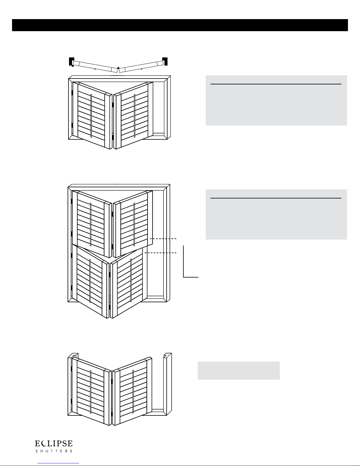
P4BY-LTLLTR with compound mitered 3 or 4 sided frame
®
Left T-post1 Left Left T-post2 Right
Bay Windows
2 1/2” 3 1/2” 4 1/2”
• Minimum Width:
• Maximum Width: 108” 108” 108”
• Minimum Height:
• Maximum Height:
• Maximum Square Ft.:
40” 40” 40”
16” 16” 16”
120” 120” 120”
50 50 50
P4BY-LTRRTR with compound mitered 3 or 4 sided frame
Left T-post1 Right Right T-post2 Right
Note: Bay Windows also available as P3,
P5, and P6
2 1/2” 3 1/2” 4 1/2”
• Minimum Width:
• Maximum Width: 108” 108” 108”
• Minimum Height:
• Maximum Height:
• Maximum Square Ft.:
40” 40” 40”
16” 16” 16”
120” 120” 120”
50 50 50
* Void Warranty authorization is required if panels are ordered over the maximum widths, heights, square footage or divider rails not used when
required (see D4). Eclipse® reserves the right to refuse to manufacture out-of-spec, or void warranty product.
B22
Page 48

Bay Windows
®
P4BY-LTLRTR with compound mitered 3 or 4 sided frame
Left T-post Left Right T-post Right
2 1/2” 3 1/2” 4 1/2”
• Minimum Width: 40” 40” 40”
• Maximum Width: 144” 144” 144”
• Minimum Height: 16” 16” 16”
• Maximum Height: 120” 120” 120”
• Maximum Square Ft.: 50 50 50
P4BY-LLRR/Inverted Hinge with compound mitered 3 or 4 sided frame
Left Left Right Right
2 1/2” 3 1/2” 4 1/2”
• Minimum Width: 40” 40” 40”
• Maximum Width: 96” 96” 96”
• Minimum Height: 16” 16” 16”
• Maximum Height: 120” 120” 120”
• Maximum Square Ft.: 50 50 50
Note: Bay Windows also
available as P3, P5, and P6
* Void Warranty authorization is required if panels are ordered over the maximum widths, heights, square footage or divider rails not used when
B23
required (see D4). Eclipse® reserves the right to refuse to manufacture out-of-spec, or void warranty product.
Page 49

Left T-post1 Left T-post2 Right T-post3 Right
®
Left T-post1 Left T-post2 Left T-post3 Right T-post4 Right
Bow Windows
P4BW-LTLTRTR
with compound mitered 3 or 4 sided frame
2 1/2” 3 1/2” 4 1/2”
• Minimum Width: 40” 40” 40”
• Maximum Width: 144” 144” 144”
• Minimum Height: 16” 16” 16”
• Maximum Height: 120” 120” 120”
• Maximum Square Ft.: 50 50 50
P5BW-LTLTLTRTR
with compound mitered 3 or 4 sided frame
Left T-post1 Left T-post2 Left T-post3 Right T-post4 Right T-post5 Right
2 1/2” 3 1/2” 4 1/2”
• Minimum Width: 50” 50” 50”
• Maximum Width: 180” 180” 180”
• Minimum Height: 16” 16” 16”
• Maximum Height: 120” 120” 120”
• Maximum Square Ft.: 50 50 50
P6BW-LTLTLTRTRTR
with compound mitered 3 or 4 sided frame
2 1/2” 3 1/2” 4 1/2”
• Minimum Width: 60” 60” 60”
• Maximum Width: 216” 216” 216”
• Minimum Height: 16” 16” 16”
• Maximum Height: 120” 120” 120”
• Maximum Square Ft.: 60 60 60
Note: If Interlock is required, note request on Order Form.
* Void Warranty authorization is required if panels are ordered over the maximum widths, heights, square footage or divider rails not used when
required (see D4). Eclipse® reserves the right to refuse to manufacture out-of-spec, or void warranty product.
B24
Page 50

Café Style
®
A Café style shutter is a shutter configuration in which the panel or panels do not completely cover
the entire height of the window opening. The frame may be ordered to the same height as the
panel (in 2 or 3 sided frame configurations) or the frame may be ordered at a different height than
the panel (4 sided configurations). In a 4 sided Café Style configuration, please note the ordered
height and width on the Regular Order Form. Under the remarks section of the order form, note the
height of the panel.
If ordering a 3-sided inverted frame in which the panel and frame are the same height, then order
as an “IF”. (Example: P2IF, page B5)
P1-L (Shown Below)
Opening
(ordered)
height
Panel height from bottom of shutter frame
or sill to top of panel.
For outside mount, panel height is the measurement from the
bottom of the frame to the top of the panel.
* Void Warranty authorization is required if panels are ordered over the maximum widths, heights, square footage or divider rails not used
B25
when required (see D4). Eclipse® reserves the right to refuse to manufacture out-of-spec, or void warranty product.
Page 51

C
OPERATING AND
DEPTH CLEARANCE
Inside Mount with No Frame (Direct Mount) C1
Inside Mount with Mounting Strip and Bent-leaf Hinge C2
Recessed Inside Mount with L-Frame C3
Inside Mount with Casing Sill Frame C4
Inside Mount with Z-Frame C5
Inside Mount with Trim Frame with Flex C6
Inside Mount with Bullnose Z Frame with Flex C7
Inside Mount with Deluxe Trim Frame C8
Outside Mount with L-Frame C9
Outside Mount Beside Trim with L-Frame C10
Outside Mount with Casing Frame C11
Outside Mount on Existing Trim with Casing Frame C12
Frame Deduction Summary C13
Page 52

Clearance Charts
Inside Mount with No Frame (direct mount)
Depth Clearance
With UltraClearview With Tilt Bar
2 1/2” Louver = 2 1/2” 2 1/2” Louver = 1 7/8”
3 1/2” Louver = 3” 3 1/2” Louver = 2 3/8”
4 1/2” Louver = 3 1/2” 4 1/2” Louver = 2 7/8”
Note: With optional 1 1/4” extended
leaf hinges, the depth clearance for
shutters with tilt bar can be reduced
by 5/8” to 1 3/8” for 2 1/2” louver,
1 7/8” for 3 1/2” louver, and 2 3/8”
for 4 1/2” louver.
* Void Warranty authorization is required if panels are ordered over the maximum widths, heights, square footage or divider rails not used
C1
when required (see D4). Eclipse® reserves the right to refuse to manufacture out-of-spec, or void warranty product.
Page 53

Inside Mount with 3/4” x 3/4” Mounting Strip
and Bent-leaf Hinge
Clearance Charts
Depth Clearance
With UltraClearview With Tilt Bar
2 1/2” Louver = 2 1/2” 2 1/2” Louver = 2 1/8”
3 1/2” Louver = 3” 3 1/2” Louver = 2 3/8”
4 1/2” Louver = 3 1/2” 4 1/2” Louver = 2 7/8”
Note: Depth clearance can be reduced
to 1” if mounting strip is installed
closer to the inside of opening.
However, hinges will project
into the room by 1”.
* Void Warranty authorization is required if panels are ordered over the maximum widths, heights, square footage or divider rails not used
when required (see D4). Eclipse® reserves the right to refuse to manufacture out-of-spec, or void warranty product.
C2
Page 54

Clearance Charts
Recessed Inside Mount with L-Frame
Depth Clearance
With UltraClearview With Tilt Bar
2 1/2” Louver = 2 1/2” 2 1/2” Louver = 2 1/8”
3 1/2” Louver = 3” 3 1/2” Louver = 2 3/8”
4 1/2” Louver = 3 1/2” 4 1/2” Louver = 3”
Note: For recessed mounts the depth
clearance is measured from
the front of L-Frame. Only
L-Frame can be used in a
recessed mount application.
Recessed distance can vary.
* Void Warranty authorization is required if panels are ordered over the maximum widths, heights, square footage or divider rails not used
C3
when required (see D4). Eclipse® reserves the right to refuse to manufacture out-of-spec, or void warranty product.
Page 55

Recessed Inside Mount with Casing Sill Frame
Clearance Charts
Depth Clearance
With UltraClearview With Tilt Bar
2 1/2” Louver = 2 1/2” 2 1/2” Louver = 2 1/2”
3 1/2” Louver = 3” 3 1/2” Louver = 2 1/2”
4 1/2” Louver = 3 1/2” 4 1/2” Louver = 3”
Note: Depth clearance is the minimum
window opening depth required for
shutters to operate without interference.
* Void Warranty authorization is required if panels are ordered over the maximum widths, heights, square footage or divider rails not used
when required (see D4). Eclipse® reserves the right to refuse to manufacture out-of-spec, or void warranty product.
C4
Page 56

Clearance Charts
Inside Mount with Z-Frame
Depth Clearance
With UltraClearview With Tilt Bar
2 1/2” Louver = 1 5/8” 2 1/2” Louver = 1 1/4”
3 1/2” Louver = 2 1/8” 3 1/2” Louver = 1 5/8”
4 1/2” Louver = 2 5/8” 4 1/2” Louver = 2 1/8”
Depth clearance is the
Note:
minimum window
opening depth required
for shutters to operate
without interference.
* Void Warranty authorization is required if panels are ordered over the maximum widths, heights, square footage or divider rails not used
C5
when required (see D4). Eclipse® reserves the right to refuse to manufacture out-of-spec, or void warranty product.
Page 57

Inside Mount with Trim Frame with Flex
Clearance Charts
Depth Clearance
With UltraClearview With Tilt Bar
2 1/2” Louver = 1 1/2” 2 1/2” Louver = 1 1/8”
3 1/2” Louver = 2” 3 1/2” Louver = 1 1/2”
4 1/2” Louver = 2 1/2” 4 1/2” Louver = 2”
Note: Depth clearance is the
minimum window opening
depth required for shutters
to operate without interference.
* Void Warranty authorization is required if panels are ordered over the maximum widths, heights, square footage or divider rails not used
when required (see D4). Eclipse® reserves the right to refuse to manufacture out-of-spec, or void warranty product.
C6
Page 58

Clearance Charts
Inside Mount with Bullnose Z Frame with Flex
Depth Clearance
With UltraClearview With Tilt Bar
2 1/2” Louver = 1 3/4” 2 1/2” Louver = 1 3/8”
3 1/2” Louver = 2 1/4” 3 1/2” Louver = 1 5/8”
4 1/2” Louver = 2 3/4” 4 1/2” Louver = 2 1/8”
Depth clearance is the
Note:
minimum window opening
depth required for shutters to
operate without interference.
* Void Warranty authorization is required if panels are ordered over the maximum widths, heights, square footage or divider rails not used
C7
when required (see D4). Eclipse® reserves the right to refuse to manufacture out-of-spec, or void warranty product.
Page 59

Inside Mount with Deluxe Trim Frame
Clearance Charts
Depth Clearance
With UltraClearview With Tilt Bar
2 1/2” Louver = 1 1/2” 2 1/2” Louver = 1 1/8”
3 1/2” Louver = 2” 3 1/2” Louver = 1 1/2”
4 1/2” Louver = 2 1/2” 4 1/2” Louver = 2”
Note: Depth clearance is the
minimum window opening
depth required for shutters
to operate without interference.
* Void Warranty authorization is required if panels are ordered over the maximum widths, heights, square footage or divider rails not used
when required (see D4). Eclipse® reserves the right to refuse to manufacture out-of-spec, or void warranty product.
C8
Page 60

Clearance Charts
Outside Mount with L Frame
Depth Clearance
With UltraClearview With Tilt Bar
2 1/2” Louver = 3/8” 2 1/2” Louver = 0”
3 1/2” Louver = 7/8” 3 1/2” Louver = 1/2”
4 1/2” Louver = 1 3/8” 4 1/2” Louver = 7/8”
Depth clearance is the
Note:
minimum window opening
depth required for shutters to
operate without interference.
* Void Warranty authorization is required if panels are ordered over the maximum widths, heights, square footage or divider rails not used
C9
when required (see D4). Eclipse® reserves the right to refuse to manufacture out-of-spec, or void warranty product.
Page 61

Outside Mount Beside Trim with L Frame
Clearance Charts
Depth Clearance
With UltraClearview With Tilt Bar
2 1/2” Louver = 0” 2 1/2” Louver = 0
3 1/2” Louver = 0” 3 1/2” Louver = 0”
4 1/2” Louver = 0” 4 1/2” Louver = 0”
Note: Depth clearance is the
minimum window opening
depth required for shutters
to operate without interference.
* Void Warranty authorization is required if panels are ordered over the maximum widths, heights, square footage or divider rails not used
when required (see D4). Eclipse® reserves the right to refuse to manufacture out-of-spec, or void warranty product.
C10
Page 62

Clearance Charts
Outside Mount with Casing Frame
Depth Clearance
With UltraClearview With Tilt Bar
2 1/2” Louver = 0” 2 1/2” Louver = 0”
3 1/2” Louver = 1/2” 3 1/2” Louver = 0”
4 1/2” Louver = 1” 4 1/2” Louver = 5/8”
Depth clearance is the
Note:
minimum window opening
depth required for shutters to
operate without interference.
* Void Warranty authorization is required if panels are ordered over the maximum widths, heights, square footage or divider rails not used
C11
when required (see D4). Eclipse® reserves the right to refuse to manufacture out-of-spec, or void warranty product.
Page 63

Clearance Charts
Outside Mount on Top of Existing Trim with Casing Frame
Depth Clearance
With UltraClearview With Tilt Bar
2 1/2” Louver = 0” 2 1/2” Louver = 0
3 1/2” Louver = 0” 3 1/2” Louver = 0”
4 1/2” Louver = 3/8” 4 1/2” Louver = 0”
Note: Depth clearance is the
minimum window opening
depth required for shutters
to operate without interference.
* Void Warranty authorization is required if panels are ordered over the maximum widths, heights, square footage or divider rails not used
when required (see D4). Eclipse® reserves the right to refuse to manufacture out-of-spec, or void warranty product.
C12
Page 64

Bullnose Z Frame with Flex 3/8" 1/4"
Casing Frame 0" 0"
Width
Height
Width
Clearance Charts
Frame Deduction Summary
IM Deduction No Sill IM Deduction With Sill
Deluxe Trim Frame 1/4" 1/8"
Trim Frame with Flex 3/8" 1/4"
Z Frame 1/4" 1/8"
Casing Sill Frame 1/8" NA
L Frame 1/8" NA
IM Deduction No Sill IM Deduction With Sill
Deluxe Trim Frame 1/4" 1/8"
Bullnose Z Frame with Flex 3/8" 1/4"
Trim Frame with Flex 3/8" 1/4"
Z Frame 1/4" 1/8"
Casing Sill Frame 1/8" NA
L Frame 1/8" NA
OM Deduction No Sill OM Deduction With Sill
Casing Sill Frame 0" NA
L Frame 0" NA
Height
OM Deduction No Sill OM Deduction With Sill
Casing Frame 0" 0"
Casing Sill Frame 0" NA
L Frame 0" NA
* Void Warranty authorization is required if panels are ordered over the maximum widths, heights, square footage or divider rails not used
C13
when required (see D4). Eclipse® reserves the right to refuse to manufacture out-of-spec, or void warranty product.
Page 65

D
DESIGNING
THE RIGHT SHUTTER
Helpful Hints D1
Options
Obstructions
Depth Clearances
Single Panel
Bi-fold Panels
Shutters with Uneven Panel Widths D2
Uneven Panel Widths without a T-Post
Uneven Panel Widths with T-Posts
Importance of Height Consistency D3
Locating Divider Rails D4
Measurement
Matching Divider Rail Locations
Double Hung Shutters D5
Horizontal T Posts
Page 66

Helpful Hints
• Follow the general rules below when choosing a shutter style.
• Record all details on an Eclipse® Order Form to ensure accurate record.
• Use a steel measuring tape to take measurements.
Options
Before measuring, discuss the various
options available with your customer.
• louver size
• frames vs no frames
• color
• type of installation
• color of hinges
• inside or outside mount
• frame options
• divider rails
• tilt bar vs. UltraClearview
• shutter configuration
- standard
- double hung
- café
• swing radius
Note: Shutters are room darkening but not black-out.
Obstructions
When measuring, account for obstructions
such as protruding window cranks and
window sills. Protruding cranks may
be replaced with T-handles, or can be
accommodated with projection mounts
or outside mount (refer to Section CClearance Charts). Shutters may be
installed on top of sills using either three
or four sided frames, or using four sided
L-Frames with added extensions.
Use your sample panels and frames
from your shop at home bag to ensure
clearances.
Depth clearances
This is the depth of window jamb
required for trouble free louver operation.
Measure the clearance required for desired
application (refer to Section C- Clearance
Charts). Use your sample panels and frames
from your shop at home bag to ensure proper
depth.
Single panels
The minimum single panel width is 6” and
the maximum single panel width is 36”.
Note: Warranty is void on oversized panels.
Bi-fold panels (shown as LL [Left Bi-fold]
or RR [Right Bi-fold])
A maximum of two panels may be hinged
together. The combined widths may not
exceed 48”.
T Post
The 1 1/4” T Post has been designed to
accept aluminum reinforcement. Aluminum
reinforcement is available upon request.
* Void Warranty authorization is required if panels are ordered over the maximum widths, heights, square footage or divider rails not used
D1
when required (see D4). Eclipse® reserves the right to refuse to manufacture out-of-spec, or void warranty product.
Page 67

Shutters with Uneven Panel Widths
Uneven Panel Widths without a T-Post
1. Draw a sketch of the opening.
2. Measure total width and height.
O.M.=Outside frame to outside frame
I.M.=Opening size
3. Record number of panels and hinge style
(i.e., P4-LLRR).
4. Measure from the left side:
A. From the left edge of the frame to the
right edge of the first panel for an outside
mount or from the left inside opening to
the right edge of the first panel for an
inside mount.
B. For any middle panels measure from the
left edge to the right edge of each panel.
C. For the right panel, measure from the left
edge of the last panel to the right edge of
the frame for an outside mount, or to the
right inside opening for inside mount.
L-Panel
A
L-Panel
A
Outside Mount
Width
L-Panel
B
Inside Mount
Width
L-Panel
B
R-Panel
B C
R-Panel
B C
R-Panel
Height
R-Panel
Height
5. Record these measurements in the “Uneven
Panel Widths Section” of the Eclipse® Order
Form. The panel widths added together
should equal the total overall width.
Uneven Panel Widths with T-Posts
1. Draw a sketch of the window.
2. Measure total width and height.
O.M.=Outside frame to outside frame
I.M.=Opening size
3. Record number of panels and hinge style
(i.e., P3-LTLTR).
4. All T-Post distances are measured starting
from left side of opening frame to center of
each T-Post.
5. Record these measurements in the “Uneven
T-Post Distances” section of the Eclipse®
Order Form.
Outside Mount
Width
L-Panel L-Panel R-Panel
T-Post
A
B
Inside Mount
Width
L-Panel L-Panel R-Panel
T-Post
A
B
Height
Height
* Void Warranty authorization is required if panels are ordered over the maximum widths, heights, square footage or divider rails not used
when required (see D4). Eclipse® reserves the right to refuse to manufacture out-of-spec, or void warranty product.
D2
Page 68

Importance of Height Consistency
• Shutter height is made up of a unique combination of:
1) a top rail
2) a bottom rail
3) a number of evenly spaced louvers
4) a divider rail if over 60” tall (50” if bifold)
• The divider rail widths are constant. The distance between louvers
is constant. Only a specific number of top and bottom rail
combinations are possible.
• To achieve a uniform appearance, with same top, bottom and
divider rail placement, as well as maintain an equal number of louvers
in adjacent shutters, all shutters must be ordered the same height.
If the height measurements differ,
apply one of the three options below:
1 For inside mount without
frame or L-Frame, reduce taller
height measurement by 1/8” max.;
order shutters same height.
For inside mount with Z-Frame,
2
Trim Frame, or Deluxe Trim Frame,
reduce 1/2” max. from tallest height
measurement; order shutters
same height.
3 For height adjustments of more
than 1/2”, go to an outside mount;
order shutters same height.
Top Rail
Louvers
Divider Rail
Bottom Rail
* Void Warranty authorization is required if panels are ordered over the maximum widths, heights, square footage or divider rails not used
D3
when required (see D4). Eclipse® reserves the right to refuse to manufacture out-of-spec, or void warranty product.
Page 69

Locating Divider Rails
Divider rail is required if shutter panel height is over 60” (50” if bifold). A second divider rail
is required if panel height is over 90”. Distance between rails must be less than 50”. Although
added strength is the main feature of a divider rail, it also allows bottom louvers to be fully
closed for privacy and top louvers open for light.
Top Operating Louvers
Divider Rail
OUTSIDE MOUNT
“Distance-up” is the
distance from the
bottom frame to
the center of where
you would like the
divider rail located.
Note: Center line location of divider rails may vary up or down by a maximum of 1” for 2 1/2” louver, by
Bottom Operating Louvers
INSIDE MOUNT
“Distance-up” is the distance
from the top of the sill to the
center of where you would
like the divider rail located.
1 1/2” for 3 1/2” louver, and 2” for 4 1/2” louver. For adjacent openings to have same divider location the
height must be same.
Matching Divider Rail Locations
When divider rails are desired at a similar height from the floor, from window to window, or from room to room,
measure height of center of divider rail from the floor up to the same point on the second window, then measure down
to the bottom of the shutter. This measurement down is the “distance-up.” If you require a specific divider rail location,
please specify in the remarks section on the order form. If it is not possible, we will contact you with the options.
Divider Rail Widths
• 2 1/2” and 4 1/2” louvers have a divider rail width of 3 3/4”
• 3 1/2” louvers have a divider rail width of 2 5/8”
* Void Warranty authorization is required if panels are ordered over the maximum widths, heights, square footage or divider rails not used
when required (see D4). Eclipse® reserves the right to refuse to manufacture out-of-spec, or void warranty product.
D4
Page 70

Double Hung Shutters
Double hung shutters are panels stacked vertically within a single framed shutter unit.
• Double hungs with no horizontal T-post include a 1/8” gap between panels
• An optional 1 1/4” horizontal T-post is available for added strength. (specify in the given space at the bottom
right of the order form)
• Location of split between panels or the center of the horizontal T-post is required as is measured from bottom of
opening.
• Minimum panel height is 16” for both panels, which means the minimum split height is also 16”.
1/8” gap
between
panels
Top Panel
1 1/4”
Horizontal
T-post
T-post blocks
for installation
Bottom Panel
* Void Warranty authorization is required if panels are ordered over the maximum widths, heights, square footage or divider rails not used
D5
when required (see D4). Eclipse® reserves the right to refuse to manufacture out-of-spec, or void warranty product.
Page 71

®
E
MEASURING GUIDE
Inside Mount E1
Outside Mount E2
Bay Windows E3-10
Inside Mount - 3 Individual Openings E3
Inside Mount - Compound Miter Window E4
Inside Mount - Two Sided Frame or No Frame E5
Inside Mount - 3 Adjacent L-Frames E6
Outside Mount - 3 Adjacent L-Frames E7
Outside Mount - Two Sided Frame E8
Outside Mount - Compound Miter on Top of Trim E9
Outside Mount - Compound Miter without Trim E10
Bow Windows E11-15
Inside Mount - Compound Miter E11
Inside Mount - Two Sided Frame, or No Frame E12
Outside Mount - Two Sided Frame E13
Outside Mount - Compound Miter on Top of Trim E14
Outside Mount - Compound Miter without Trim E15
Page 72

®
E
MEASURING GUIDE (Continued)
Patio Doors E16-17
Inside Mount E16
Outside Mount E17
Corner Windows E18-19
Inside Mount E18
Outside Mount E19
Page 73

Z-Frame, Trim Frame, Bullnose Z Frame, Deluxe
Trim Frame, L-Frame, Mounting Strip or No Frame
Inside Mount
1. CHOICE OF FRAME & LOUVER
• The appropriate frame will be affected by the mount
type, depth clearance, existing trim, etc.
• Use samples panels, frames and color samples from
the shop at home bag.
• Make sure that the chosen frame and louver size will
function properly once installed into the opening.
• Ensure the chosen application will overcome any
possible obstructions such as latches, cranks or
windows that open into the room.
• Number of frame sides is based on the configuration
and type of shutter. Four sided frames are recommended
for most standard shutters.
• Frame Extensions are not available for inside
mount applications.
2. INSIDE MOUNT vs. OUTSIDE MOUNT
• Check for squareness by measuring the diagonal
and/or use a sample panel and place at each corner.
• If the diagonal measurements are not identical, a framed
application is recommended for inside mounts. An
unframed application will result in uneven light gaps.
• If the diagonal measurements are out more than 3/8”,
then an outside mount is recommended.
• If the proper clearance is not available, an outside mount
may be necessary for larger louvers and/or the
Clearview joiners.
3. MEASURE INSIDE WIDTH
• Measure the width in three places (top, middle & bottom)
and record the smallest measurement to 1/8”.
• For windows with vertical mullions, match the panel
widths to each section of the window with or without
T Posts. (See Page D2 for measuring instructions)
4. MEASURE INSIDE HEIGHT
• Measure the height in three places (left, middle & right)
and record the smallest measurement to 1/8”.
Inside Measurements
5. DIVIDER RAILS
• Measure from the bottom of the sill to the middle of the
divider rail location.
• One divider rail is required for panels over 60” in height
with a maximum 50” between the middle of the divider
rail and either top or bottom rail.
• Two divider rails are required for panels over 90” in
height with a maximum 50” between any two rails.
• Refer to Page D4 for additional divider rail
measuring instructions.
A B
Diagonal Squareness Check
®
E1
Page 74

Outside Mount
Casing Frame or L-Frame
1. CHOICE OF LOUVER & FRAME
• Use samples panels, frames and color samples
from the shop at home bag.
• Make sure that the chosen frame and louver size
will function properly once installed into the opening.
• Ensure the chosen application will overcome any
possible obstructions such as latches, cranks or
windows that open into the room.
• The minimum width of trim required for Casing Frame is
2 5/8”, L-Frame is 1 3/8”.
If the trim width is less than the frame width, then the frame
should extended outside of the trim, not inside the opening.
• Number of frame sides is based on the configuration
and type of shutter. Four sided frames are recommended
for most standard shutters.
• Depth clearance and obstructions can prevent louvers from
operating properly. In order to overcome these obstacles,
add the necessary frame extensions to the appropriate frame.
• Frame Extensions are available for outside mount
applications. Up to (3) 1/2” extensions can be
added to either frame for greater protection.
2. INSIDE MOUNT vs. OUTSIDE MOUNT
• Outside mount shutters may be necessary for larger louvers
and/or the UltraClearview system
• If windows include trim, outside mount shutters may be
installed on top of, or next to the trim.
• If windows do not include trim, then the shutters are mounted
where the trim would be.
If installing around trim
• Measure from outside of trim to outside of trim in three places
(top, middle & bottom). Add 1 3/8” per frame side for
L-Frame only. Record the largest measurement to 1/8”.
4. MEASURE OUTSIDE HEIGHT
If on top of trim
• Measure from outside of trim to outside of trim in three places
(left, middle & right). Ensure the frame does not extend into the
opening. Record the largest measurement to 1/8”.
• If the chosen frame extends past the edge of the trim, then
measure the height from outside of trim to outside of trim in
three places (top, middle & bottom). Add it to the
measurement that the frame extends past the trim on each side.
If no trim
• Measure the inside height in three places (left, middle & right).
Take the largest measurement to 1/8” and add 2 5/8” per
frame side for Casing Frame, 1 3/8” per side for L-Frame.
If installing around trim
• Measure from outside of trim to outside of trim in three places
(left, middle & right). Add 1 3/8” per frame side for L-Frame
only. Record the largest measurement to 1/8”.
3. MEASURE OUTSIDE WIDTH
If on top of trim
• Measure from outside of trim to outside of trim in three places
(top, middle & bottom). Ensure the frame does not extend into
the opening. Record the largest measurement to 1/8”.
• If the chosen frame extends past the edge of the trim, then
measure the width from outside of trim to outside of trim in
three places (top, middle & bottom). Add it to the
measurement that the frame extends past the trim on
each side.
If no trim
• Measure the inside width in three places (top, middle &
bottom). Take the largest measurement to 1/8” and add 2
5/8” per frame side for Casing Frame.
®
E2
Outside Measurements
5. DIVIDER RAILS
• Measure from the bottom of the bottom frame to the middle of
the divider rail location.
• One divider rail is required for panels over 60” in height with
a maximum 50” between the middle of the divider rail and
either top or bottom rail.
• Two divider rails are required for panels over 90” in height
with a maximum 50” between any two rails.
• Refer to Page D4 for additional divider rail measuring
instructions.
Page 75

Bay Window
Inside Mount: 3 Individual Openings - Z-Frame, Trim Frame, Bullnose
Z Frame, Deluxe Trim Frame, L-Frame, Mounting Strip or No Frame
1. CHOICE OF LOUVER & FRAME
• Use samples panels, frames and color samples from
the shop at home bag.
• Make sure that the chosen frame and louver size will
function properly once installed into the opening.
• Ensure the chosen application will over come any
possible obstructions such as latches, cranks or
windows that open into the room.
• Number of frame sides is based on the configuration
and type of shutter. Four sided frames are
recommended for most standard shutters.
• Frame Extensions are not available for inside
mount applications.
2. INSIDE MOUNT vs. OUTSIDE MOUNT
• Check for squareness by measuring the diagonal
and/or use a sample panel and place at each corner.
• If the diagonal measurements are not identical, a
framed application is recommended for inside mounts.
An unframed application will result in uneven
light gaps.
• If the diagonal measurements are out more than 3/8”,
then an outside mount is recommended.
• If the proper clearance is not available, an outside
mount may be necessary for larger louvers and/or the
UltraClearview system.
4. MEASURE INSIDE HEIGHT (Each opening)
• Measure width at left, middle and right and record the
smallest measurement to 1/8”.
Inside Measurements
5. DIVIDER RAILS
• Measure from the bottom of the sill to the middle of the
divider rail location.
• One divider rail is required for panels over 60” in
height with a maximum 50” between the middle of the
divider rail and either top or bottom rail.
• Two divider rails are required for panels over 90” in
height with a maximum 50” between any two rails.
• Refer to Page D4 for additional divider rail
measuring instructions.
3. MEASURE INSIDE WIDTH (Each opening)
• Measure width at top, middle and bottom and record
the smallest measurement to 1/16”.
• For windows with vertical mullions, match the panel
widths to each section of the window with or without
T Posts. (See Page D2 for measuring instructions)
®
E3
Page 76

Bay Window
Inside Mount Compound Miter - Z-Frame, Trim Frame, Bullnose Z Frame,
Deluxe Trim Frame or L-Frame
(Use Bay Window Order Form)
1. CHOICE OF FRAME & MOUNT TYPE
• Use samples panels, frames and color samples from the
shop at home bag.
• Make sure that the chosen frame and louver size will
function properly once installed into the opening.
• Ensure the chosen application will overcome any possible
obstructions such as latches, cranks or windows that open
into the room.
• If the proper clearance is not available, an outside mount
may be necessary for larger louvers and/or the
UltraClearview system.
• If the diagonal measurements of each opening are out more
than 3/8”, then an outside mount is recommended.
• Number of frame sides is based on the configuration and
type of shutter. Four sided frames are recommended
for most standard shutters.
• Frame Extensions are not available for inside mount
applications.
• A Sill Frame is only available on the Z, Trim, Bullnose Z and
Deluxe Trim Frames. Unless otherwise requested, the Sill Frame
will be placed on the bottom. The Sill Frame can also be
requested for the top or either side.
2. DETERMINE MOUNTING PROJECTION
• Place chosen frame against the left bottom sill of the “A”
opening and make a 3” pencil mark at the back of the
frame from the inside jamb.
• Slide the frame along the bottom sill to the right side of the
“A” opening. Make a 3” pencil mark at the back of the
frame to the right side.
• Follow the same process for openings B & C.
• Use a flat edge to extend the lines at each corner until
they intersect.
• Repeat the process for the top sill.
3. MEASURE INSIDE WIDTH
(Openings A, B, & C)
• Measure opening “A” from the pencil mark on
the left side of the opening to the intersection of
lines at angle 1 at both the bottom and top of the window
opening. Record the narrowest measurement to 1/16”.
• Measure opening “B” from the intersection of lines at angle
1 to the intersection of lines at angle 2 at both the top and
bottom of the window opening. Record the narrowest
measurement to 1/16”.
• Measure opening “C” from the intersection of lines at angle
2 to the pencil mark on the right side of the opening at both
top and bottom of the window opening. Record the
narrowest measurement to 1/16”.
4. MEASURE INSIDE HEIGHT (Openings A, B, & C)
• Measure height at left, middle and right and record the
smallest measurement to 1/8”.
5. DETERMINE THE ANGLES
• Using a protractor, measure both angles at points
1 and 2 at the top and bottom.
• If angles are not the same on the top and bottom,
split the difference.
6. DIVIDER RAILS
• Measure from the bottom of the sill to the middle
of the divider rail location.
• One divider rail is required for panels over 60” in height
with a maximum 50” between the middle of the divider rail
and either top or bottom rail.
• Two divider rails are required for panels over 90” in height
with a maximum 50” between any two rails.
• Refer to Page D4 for additional divider rail measuring
instructions.
7. SURCHARGE IS APPLICABLE
• Compound Miter Bay Window will incur a surcharge.
1
B
B
Read Angle
C
Height
2
C
A
A
Fit the top edge of the large card and the right hand
edge of the smaller card into the angle, as indicated
in the diagram at left. The arrow will point to the
degree of the angle.
®
E4
Page 77

Bay Window
Inside Mount with Two Sided Frame - Z-Frame, Trim Frame, Bullnose
Z Frame, Trim Frame, Deluxe Trim Frame, or No Frame
(Use Regular Shutter Order Form)
1. CHOICE OF LOUVER & FRAME
• Use samples panels, frames and color samples
from the shop at home bag.
• Make sure that the chosen frame and louver size will
function properly once installed into the opening.
• Ensure the chosen application will overcome any
possible obstructions such as latches, cranks or
windows that open into the room.
• Number of frame sides is based on the configuration
and type of shutter. Four sided frames are
recommended for most standard shutters.
2. INSIDE MOUNT vs. OUTSIDE MOUNT
• Check for squareness by measuring the diagonal
and/or use a sample panel and place at each corner.
• If the diagonal measurements are not identical, a
framed application is recommended for inside mounts.
An unframed application will result in uneven
light gaps.
• If the diagonal measurements are out more than 3/8”,
then an outside mount is recommended.
• If the proper clearance is not available, an outside
mount may be necessary for larger louvers and/or the
UltraClearview system.
3. MEASURE INSIDE WIDTHS
(Openings A, B & C)
Left Opening (A)
• Place chosen frame or panel only into place at the
extreme left side.
• Place T-Post at desired location at the left angle
perpendicular to center opening.
• Measure from the left front edge of the frame to the
middle of the front of the left T-Post.
• Enter width to 1/16” into 1st T-Post position in the
Uneven T-Post Distance box on the Regular Order Form.
• If using an inverted hinge configuration, there are no
T-Posts hence the distance is from left front edge of
opening or frame to front right edge of where panel is
to end. That measurement would be entered in the
first box under the Uneven Panel Widths.
Center Opening (B)
• Place T-Posts in the desired position. Measure distance
between middle front of each T-Post.
• The measurement between T-Posts added to the
measurements of the left opening are entered into the
2nd T-Post position to 1/16” under the Uneven T-Post
Distances box on the Regular Order Form.
• If using an inverted hinge configuration, tthe distance of
the center panels would be the exact sizes you wish
the panels to be and entered in the 2nd and 3rd
boxes under the Uneven Panel Widths.
Right Opening (C)
• Place chosen frame or panel only into place at the
extreme right side.
• Place T-Post at desired location at the right angle –
perpendicular to the center opening.
• Measure from the middle of the front of the T-Post to the
extreme right front of the frame or panel.
• The measurement of right opening added to the
distance entered in the 2nd T-Post position distances
box is the width measurement to 1/16” to be entered
as the overall width on the Regular Order Form.
• If using an inverted hinge configuration, the distance
would be from the left front edge of the center opening
to the front right edge where the panel or frame is
to end. That measurement would be entered in the
4th box under the Uneven Panel Widths.
4. MEASURE INSIDE HEIGHTS
(Openings A, B, & C)
• Measure height at left, middle and right and record the
smallest measurement to the 1/8”.
• Height measurement for all panels must be the same.
5. DIVIDER RAILS
• Measure from the bottom of the sill to the middle of the
divider rail location.
• One divider rail is required for panels over 60” in
height with a maximum 50” between the middle of the
divider rail and either top or bottom rail.
• Two divider rails are required for panels over 90” in
height with a maximum 50” between any two rails.
• Refer to Page D4 for additional divider rail
measuring instructions.
®
E5E5
Page 78

Bay Window
Inside Mount with Three Adjacent L-Frames
1. CHOICE OF LOUVER & FRAME
• Use samples panels, frames and color samples from the
shop at home bag.
• Make sure that the chosen frame and louver size will function
properly once installed into the opening.
• Ensure the chosen application will overcome any possible
obstructions such as latches, cranks or windows that open
into the room.
• Number of frame sides is based on the configuration and
type of shutter. Four sided frames are recommended for most
standard shutters.
• Frame extensions are not available for inside mount
applications.
2. INSIDE MOUNT vs. OUTSIDE MOUNT
• Check for squareness by measuring the diagonal
and/or use a sample panel and place at each corner.
• If the diagonal measurements are out more than
3/8”, then an outside mount is recommended.
• If the proper clearance is not available, an outside mount
may be necessary for larger louvers and/or the
UltraClearview system.
3. MEASURE INSIDE WIDTH
(Openings A, B & C)
Left Opening (A)
• Place one L-Frame piece at the depth where the frame will be
installed at the left location and one L-Frame piece at the
depth where the frame will be installed at left side of the
left corner.
• Measure along an imaginary line that represents the front
outer edge of the L-frame. Record this width to 1/16” on line
one of the Regular Order Form.
• Measure along an imaginary line that represents the front
outer edge of the L-Frame. Record this width to 1/16” on
the second line of the Regular Order Form.
Right Opening (C)
• Place one L-Frame piece at the depth where the frame will
be installed at the right side of the right corner and one L Frame piece at the depth of the frame which will be installed
at the right location.
• Measure along an imaginary line that represents the front
outer edge of the L-Frame. Record this width to 1/16” on
the third line of the Regular Order Form.
4. MEASURE INSIDE HEIGHT
(Openings A, B & C)
• Record the smallest measurement for the heights in opening
A, B and C to 1/8”.
• Height measurement for all panels must be the same.
5. DIVIDER RAILS
• Measure from the bottom of the sill to the middle
of the divider rail location.
• One divider rail is required for panels over 60” in height
with a maximum 50” between the middle of the divider rail
and either top or bottom rail.
• Two divider rails are required for panels over 90” in height
with a maximum 50” between any two rails.
• Refer to Page D4 for additional divider rail
measuring instructions.
Center Opening (B)
• Place one L-Frame piece at the depth of the frame which will
be installed at the right side of the left corner and one of the
L-Frame pieces at the depth the frame will be installed at the
left side of the right corner.
A
1
®
E6
B
2
Measure width
along imaginary lines.
C
3
4
Page 79

(Use Regular Shutter Order Form)
Bay Window
1. CHOICE OF LOUVER & FRAME
• Use samples panels, frames and color samples
from the shop at home bag.
• Make sure that the chosen frame and louver size will
function properly once installed into the opening.
• Ensure the chosen application will overcome any
possible obstructions such as latches, cranks or
windows that open into the room.
• The appropriate frame will be affected by the mount
type, depth clearance, existing trim, etc.
• Number of frame sides is based on the configuration
and type of shutter. Four sided frames are
recommended for most standard shutters.
• Specify the number of L-Frame extensions required for
proper louver operation.
2. INSIDE MOUNT vs. OUTSIDE MOUNT
• Check for squareness by measuring the diagonal
and/or use a sample panel and place at each corner.
• If the proper clearance is not available, an outside
mount may be necessary for larger louvers and/or the
UltraClearview system.
• Measure along an imaginary line that represents the
front outer edge of the frame. Record width
measurement to 1/16” on a third line on a
Regular Order Form.
4. MEASURE INSIDE HEIGHT
(Openings A, B & C)
• Record the largest measurement for the heights in
opening A, B and C to 1/8”.
• Height measurement for all panels must be the same.
5. DIVIDER RAILS
• Measure from the bottom of the sill to the middle of the
divider rail location.
• One divider rail is required for panels over 60” in
height with a maximum 50” between the middle of the
divider rail and either top or bottom rail.
• Two divider rails are required for panels over 90” in
height with a maximum 50” between any two rails.
• Refer to Page D4 for additional divider rail
measuring instructions.
3. MEASURE INSIDE WIDTH
(Openings A, B & C)
Left Opening (A)
• Place one piece of L-Frame on the left side
of opening where the frame will be installed. Using a
second piece of frame, place it on the rightside of
Opening A (or on the left side of Angle 1).
• Measure along an imaginary line that represents the
front outer edge of the frame. Record this width to
1/16” on line one on a Regular Order Form.
Center Opening (B)
• Place one piece of L-Frame on the left side
of Opening B (or on the right side of Angle 1). Place
second frame piece on the right side of Opening B (or
on the left side of Angle 2).
• Measure along an imaginary line that represents the
front outer edge of the frame. Record this width to
1/16” on a second line on a Regular Order Form.
Right Opening (C)
• Place one piece of L-Frame on the left side
of Opening C (or on the right side of Angle 2). Place
second frame piece on the right side of Opening C
where the frame will be installed.
A
B
Angle 1
Measure width along
imaginary lines.
C
Angle 2
®
E7
Page 80

Bay Window
Outside Mount with Two Sided Frame L-Frame or Casing Frame
1. CHOICE OF LOUVER & FRAME
• Use samples panels, frames and color samples from the shop
at home bag.
• Make sure that the chosen frame and louver size will function
properly once installed into the opening.
• Ensure the chosen application will overcome any possible
obstructions such as latches, cranks or windows that open
into the room.
• Number of frame sides is based on the configuration and
type of shutter. Four sided frames are recommended for most
standard shutters.
2. INSIDE MOUNT vs. OUTSIDE MOUNT
• Check for squareness by measuring the diagonal and/or use
a sample panel and place at each corner.
• If the proper clearance is not available, an outside mount
may be necessary for larger louvers and/or the
UltraClearview system.
3. MEASURE INSIDE WIDTH
(Openings A, B & C)
Left Opening (A)
• Place chosen frame (with any extension if needed) into place
at the extreme left side.
• Place T-Post at desired location at the left angle -
perpendicular to center opening.
• Measure from the left front edge of the frame to the middle of
the front of the left T-Post.
• Enter width to 1/16” into 1st T-Post position in the Uneven T Post Distance box on the Regular Order Form.
• If using an inverted hinge configuration, there are no T-Posts,
hence the distance is from left front edge of opening or frame
to front right edge of where panel is to end. That measurement
would be entered in the first box under the Uneven Panel Widths.
Center Opening (B)
• The measurement between T-Posts added to the measurements
of the left opening are entered into the 2nd T-Post position
under the Uneven T-Post distances box to 1/16” on the
Regular Order Form.
• If using an inverted hinge configuration, there are no T-Posts,
hence the distance of the center panels would be the exact
sizes you wish the panels to be and entered in the 2nd and
3rd boxes under the Uneven Panel Widths.
Right Opening (C)
• Place chosen frame (with any extension if needed) at the
extreme right side.
• Place T-Post at desired location at the right angle
– perpendicular to the center opening.
• Measure from the middle of the front of the T-Post to the
extreme right front of the frame or panel.
• The measurement of right opening added to the distance
entered in the 2nd T-Post position distances box is the width
measurement to be entered as the overall width to 1/16” on
the Regular Order Form.
• If using an inverted hinge configuration, there are no T-Posts
therefore the distance would be from the left front edge of the
center opening to the front right edge where the panel or
frame is to end. That measurement would be entered in the
4th box under the Uneven Panel Widths.
4. MEASURE INSIDE HEIGHT
(Openings A, B & C)
• Measure height at left, middle, and right and record
the smallest measurement to 1/8”, then deduct 1/4” for
height clearance.
• Height measurement for all panels must be the same.
5. DIVIDER RAILS
• Measure from the bottom of the sill to the middle
of the divider rail location.
• One divider rail is required for panels over 60” in height with
a maximum 50” between the middle of the divider rail and
either top or bottom rail.
• Two divider rails are required for panels over 90” in height
with a maximum 50” between any two rails.
• Refer to Page D4 for additional divider rail
measuring instructions.
®
E8
Page 81

Outside Mount Compound Miter on Top of Trim Casing Frame or L-Frame (Use Bay Order Form)
Bay Window
1. CHOICE OF FRAME & MOUNT TYPE
• Use samples panels, frames and color
samples from the shop at home bag.
• Make sure that the chosen frame and louver size will
function properly once installed into the opening.
• The appropriate frame will be affected by
the mount type, depth clearance, existing trim, etc.
• If the proper clearance is not available, an outside
mount may be necessary for larger louvers and/or the
UltraClearview system.
• Number of frame sides is based on the configuration
and type of shutter. Four sided frames are
recommended for most standard shutters.
• Specify the number of L-Frame extensions required for
proper louver operation.
2. MEASURE WIDTHS
• If the chosen frame can be mounted flush with the edge
of the trim, then measure the widths A, B and C on top
of trim in two places (top, bottom). Record the largest
measurements to 1/16” onto a Bay Order Form.
• If the chosen frame extends past the edge of the trim,
then measure the widths A, B, C on top of trim two
places (top, bottom) and add the amount the chosen
frame extends past the trim for each side. Record
the largest measurements to 1/16” onto a
Bay Order Form.
3. MEASURE HEIGHTS
• If the chosen frame can be mounted flush with the edge
of the trim, then measure the height from outside of trim
to outside of trim in three places (left, middle, right).
Record the largest measurements to 1/8” onto a
Bay Order Form.
• If the chosen frame extends past the edge of the trim,
then measure the height from trim to trim in three places
(left, middle, right) and add the mount the chosen
frame extends past the trim for each side. Record the
largest measurements to 1/8” onto a Bay Order Form.
5. DIVIDER RAILS
• Measure from the bottom of the sill to the
middle of the divider rail location.
• One divider rail is required for panels over 60” in
height with a maximum 50” between the middle of the
divider rail and either top or bottom rail.
• Two divider rails are required for panels over 90” in
height with a maximum 50” between any two rails.
• Refer to Page D4 for additional divider rail
measuring instructions.
6. SURCHARGE IS APPLICABLE
• Compound Miter Bay Window will incur a surcharge.
B
A
B
1
A
Read Angle
Fit the top edge of the large card and the right
hand edge of the smaller card into the angle,
as indicated in the diagram at left. The arrow
will point to the degree of the angle.
2
C
Height
C
4. DETERMINE THE ANGLES
• Using a protractor, measure both angles at
points 1 and 2 at the top and bottom.
• If angles are not the same on the top and
bottom, split the difference.
®
E9
Page 82

Bay Window
Outside Mount Compound Miter without Trim Casing Frame or L-Frame (Use Bay Order Form)
1. CHOICE OF FRAME & MOUNT TYPE
• Use samples panels, frames and color samples
from the shop at home bag.
• Make sure that the chosen frame and louver size
will function properly once installed into the
opening.
• The appropriate frame will be affected by the
mount type, depth clearance, existing trim, etc.
• If the diagonal measurements of each opening
are out more than 3/8”, then an outside mount
is recommended.
• If the proper clearance is not available, an outside
mount may be necessary for larger louvers and/or
the UltraClearview system.
• Number of frame sides is based on the
configuration and type of shutter. Four sided frames
are recommended for most standard shutters.
• Specify the number of L-Frame extensions required
for proper louver operation.
2. MEASURE WIDTHS
• Measure the inside widths A, B and C in two places
top & bottom.
• Take the largest measurements to 1/16” and add 2 5/8” for
each frame side if using a Casing Frame, add 1 3/8” for
each frame side if using an L-frame.
4. DETERMINE THE ANGLES
• Using a protractor, measure both angles at
points 1 and 2 at the top and bottom.
• If angles are not the same on the top and bottom,
split the difference.
5. DIVIDER RAILS
• Measure from the bottom of the sill to the middle
of the divider rail location.
• One divider rail is required for panels over 60”
in height with a maximum 50” between the
middle of the divider rail and either top or
bottom rail.
• Two divider rails are required for panels over 90”
in height with a maximum 50” between any two rails.
• Refer to Page D4 for additional divider rail
measuring instructions.
6. SURCHARGE IS APPLICABLE
• Compound Miter Bay Window will incur a surcharge.
B
A
C
3. MEASURE HEIGHTS
• Measure the inside height in three places
(left, middle and right).
• Take the largest measurements to 1/8” and add
2 5/8” for each frame side if using a Casing
Frame, add 1 3/8” for each frame side if using
an L-Frame.
®
E10
Height
1
A
B
Read Angle
Fit the top edge of the large card and
the right hand edge of the smaller card
into the angle, as indicated in the diagram at left. The arrow will point to the
degree of the angle.
2
C
Page 83

Bow Window
Inside Mount Compound Miter - Z-Frame, Deluxe Trim Frame,
Bullnose Z Frame, Trim Frame or L-Frame (Use Bow Order Form)
1. CHOICE OF FRAME & MOUNT TYPE
• Use samples panels, frames and color
samples from the shop at home bag.
• Make sure that the chosen frame and louver size will
function properly once installed into the opening.
• The appropriate frame will be affected by the mount
type, depth clearance, existing trim, etc.
• If the diagonal measurements of each opening are out
more than 3/8”, then an outside mount is recommended.
• If the proper clearance is not available, an outside
mount may be necessary for larger louvers and/or the
UltraClearview system.
• Number of frame sides is based on the configuration
and type of shutter. Four sided frames are
recommended for most standard shutters.
• Frame Extensions are not available for inside
mount applications.
2. DETERMINE MOUNTING PROJECTION
• Place chosen frame against the left sill of the “A”
opening and make a 3” pencil mark at the back of the
frame from the inside jamb.
• Slide the frame along the sill to the right side of the “A”
opening. Make a 3” pencil mark at the back of the
frame to the right side.
• Follow the same process for openings B & C.
• Use a flat edge to extend the lines at each
corner until they intersect.
• Repeat the process for the top sill.
4. MEASURE INSIDE HEIGHTS
(A, B, C, D, & E)
• Record the smallest measurement to 1/8”.
• Height measurement for all panels must be
the same height.
5. DETERMINE THE ANGLES
• Using a protractor, measure both angles at
points 1 and 2 at the top and bottom.
• If angles are not the same on the top and bottom,
split the difference.
6. DIVIDER RAILS
• Measure from the bottom of the sill to the middle of
the divider rail location.
• One divider rail is required for panels over 60” in
height with a maximum 50” between the middle of the
divider rail and either top or bottom rail.
• Two divider rails are required for panels over 90” in
height with a maximum 50” between any two rails.
• Refer to Page D4 for additional divider rail
measuring instructions.
7. SURCHARGE IS APPLICABLE
• Compound Miter Bay Window will incur a surcharge.
3. MEASURE INSIDE WIDTHS
(A, B, C, D, & E)
• Measure “A” width - from the pencil mark on the left
side to the intersection of lines at angle 1 at both
bottom and top. Record the narrowest measurement
to the 1/16”.
• Measure widths B, C, & D openings from the
intersection of lines at each angle to the next
intersection of lines at both bottom & top. Record the
narrowest measurement to 1/16”.
• Measure “E” widths - from intersection of lines at angle
4 to the right extreme of the pencil mark on the right
side at both bottom and top. Record the narrowest
measurement to 1/16”.
®
E11
Page 84

Bow Window
Inside Mount with Two Sided Frame or No Frame - L Frame, Z Frame,
Trim Frame, Bullnose Z Frame, Deluxe Trim Frame, or No Frame
1. CHOICE OF LOUVER & FRAME
• Use samples panels, frames and color samples from
the shop at home bag.
• Make sure that the chosen frame and louver size
will function properly once installed into the opening.
• Ensure the chosen application will overcome any possible
obstructions such as latches, cranks or windows that open
into the room.
• Number of frame sides is based on the configuration and
type of shutter. Four sided frames are recommended for most
standard shutters.
2. INSIDE MOUNT vs. OUTSIDE MOUNT
• Check for squareness by measuring the diagonal and/or use
a sample panel and place at each corner.
• If the diagonal measurements are not identical, a framed
application is recommended for inside mounts. An unframed
application will result in uneven light gaps.
• If the diagonal measurements are out more than 3/8”, then
an outside mount is recommended.
• If the proper clearance is not available, an outside mount
may be necessary for larger louvers and/or the
UltraClearview system.
3. MEASURE INSIDE WIDTHS
(A, B, C, D, & E)
Left Opening
• Place chosen frame with desired extensions or panel only to
the left jamb of the left window on the sill.
• Take a T-Post and place it at the desired location at the first
angle. Mark with a pencil the center of the first T-Post.
• Measure from the left front outer edge of the frame or panel
only to the center of left T-Post at the front. Enter that
measurement to 1/16” in the 1st T-post position under the
Uneven T-Post Distances Box.
Center Openings
• Place T-Posts into position at each corner and mark off
the center of each T-Post.
• Measure between the two T-Posts in the second opening. Add
it to the number in the 1st T-Post position under the Uneven
T-Post Distances box. Place the added number to 1/16” in the
2nd box of the Uneven T-Post Positions.
• Measure between the two T-Posts in the third opening. Add it
to the number in the 2nd T-Post position under the Uneven
T-Post Distances box. Place the added number to 1/16”in the
3rd box of the Uneven T-Post Positions.
• Measure between the two T-Posts in the fourth opening. Add it
to the measurement in the 3rd T-Post position under the Uneven
T-Post Distances box. Place the added number to 1/16” in the
4th box of the Uneven T-Post Positions.
Right Opening
• Place chosen frame or panel only to the right jamb of the
right window on the sill.
• Measure from the center of the right T-Post to the right front
outer edge of the chosen frame. That measurement added to
the measurement in the 4th box under Uneven T-Post Positions
is the over all width placed in the width box to 1/16”on
the Regular Order From.
4. MEASURE INSIDE HEIGHTS
(A, B, C, D, & E)
• Record the smallest measurement to 1/8”.
• Height measurement for all panels must be the same height.
5. DIVIDER RAILS
• Measure from the bottom of the sill to the middle
of the divider rail location.
• One divider rail is required for panels over 60” in height with
a maximum 50” between the middle of the divider rail
and either top or bottom rail.
• Two divider rails are required for panels over 90” in height
with a maximum 50” between any two rails.
• Refer to Page D4 for additional divider rail measuring
instructions.
Left T-post Left T-post Right T-post Right
®
E12
Page 85

Outside Mount with Two Sided Frame L-Frame or Casing Frame
Bow Window
1. CHOICE OF LOUVER & FRAME
• Use samples panels, frames and color samples from
the shop at home bag.
• Make sure that the chosen frame and louver size will
function properly once installed into the opening.
• Ensure the chosen application will overcome any
possible obstructions such as latches, cranks or
windows that open into the room.
2. INSIDE MOUNT vs. OUTSIDE MOUNT
• Check for squareness by measuring the diagonal
and/or use a sample panel and place at each corner.
• If the proper clearance is not available, an outside
mount may be necessary for larger louvers and/or the
UltraClearview system.
3. MEASURE OUTSIDE WIDTHS
(A, B, C, D, & E)
Left Opening
• Place chosen frame with desired extensions into place
outside the left window.
• Take a T-Post and place it at the desired location at the
first angle. Mark with a pencil the center of the first
T-Post.
• Measure from the left front outer edge of the frame to
the center of left T-Post at the front. Enter that
measurement to 1/16” in the 1st T-post position
under the Uneven T-Post Distances Box.
Center Openings
• Place T-Posts into position at each corner and
mark off the center of each T-Post.
• Measure between the two T-Posts in the second
opening. Add it to the number in the 1st T-Post position
under the Uneven T-Post Distances box. Place the
added number to 1/16” in the 2nd box of the
Uneven T-Post Distances Box.
• Measure between the two T-Posts in the third opening.
Add it to the number in the 2nd T-Post position under
the Uneven T-Post Distances box. Place the added
number to 1/16” in the 3rd box of the Uneven T-Post
Distances Box.
• Measure between the two T-Posts in the fourth opening.
Add it to the measurement in the 3rd T- Post position
under the Uneven T-Post Distances box. Place the
added number to 1/16” in the 4th box of the Uneven
T-Post Distances Box.
Right Opening
• Place chosen frame with desired extensions into place
outside the right window.
• Measure from the center of the right T-Post to the right
front outer edge of the chosen frame. That
measurement added to the measurement in the 4th box
under Uneven T-Post Distances Box is the over all width
placed in the width box to 1/16”on the Regular
Order Form.
4. MEASURE INSIDE HEIGHTS
(A, B, C, D, & E)
• Record the smallest measurement to 1/8” and deduct
1/4” height clearance.
• Height measurement for all panels must be
the same height.
5. DIVIDER RAILS
• Measure from the bottom of the sill to the middle of the
divider rail location.
• One divider rail is required for panels over 60” in
height with a maximum 50” between the middle of the
divider rail and either top or bottom rail.
• Two divider rails are required for panels over 90” in
height with a maximum 50” between any two rails.
• Refer to Page D4 for additional divider rail
measuring instructions.
Left T-post Left T-post Right T-post Right
®
E13
Page 86

Bow Window
Outside Mount Compound Miter on Top of Trim Casing Frame or L-Frame (Use Bow Order Form)
1. CHOICE OF FRAME & MOUNT TYPE
• Use samples panels, frames and color samples from
the shop at home bag.
• Make sure that the chosen frame and louver size will
function properly once installed into the opening.
• The appropriate frame will be affected by the mount type,
depth clearance, existing trim, etc.
• Specify inverted frame, if a three sided frame is being used
and the non-framed side is to be located at the top.
• If the proper clearance is not available, an outside mount
may be necessary for larger louvers and/or the
UltraClearview system.
• Number of frame sides is based on the configuration
and type of shutter. Four sided frames are recommended
for most standard shutters.
• Specify the number of L-Frame extensions required for proper
louver operation.
2. MEASURE INSIDE WIDTHS
(A, B, C, D, & E)
• If the chosen frame can be mounted flush with the edge
of the trim, then measure the widths on top of trim in two
places (top & bottom). Record the largest measurement
to 1/16” onto a Bow Order Form.
• If the chosen frame extends past the edge of the trim, then
measure the widths on top of trim in two places (top & bottom)
and add the amount the chosen frame extends past the trim for
each side. Record the largest measurement to 1/16” onto a
Bow Order Form.
4. DETERMINE THE ANGLES
• Using a protractor, measure both angles at
points 1 and 2 at the top and bottom.
• If angles are not the same on the top and bottom,
split the difference.
5. DIVIDER RAILS
• Measure from the bottom of the sill to the middle
of the divider rail location.
• One divider rail is required for panels over 60” in height
with a maximum 50” between the middle of the divider
rail and either top or bottom rail.
• Two divider rails are required for panels over 90” in height
with a maximum 50” between any two rails.
• Refer to Page D4 for additional divider rail
measuring instructions.
6. SURCHARGE IS APPLICABLE
• Compound Miter Bay Window will incur a surcharge.
Left T-post Left T-post Right T-post Right
3. MEASURE INSIDE HEIGHTS
(A, B, C, D, & E)
• If the chosen frame can be mounted flush with the edge of the
trim, then measure the height from outside of trim to outside of
trim in three places (left, middle & right). Record the largest
measurements to 1/8” onto a Bow Order Form.
®
E14
Page 87

Outside Mount Compound Miter without Trim Casing Frame or L-Frame (Use Bow Order Form)
Bow Window
1. CHOICE OF FRAME & MOUNT TYPE
• Use samples panels, frames and color samples from
the shop at home bag.
• Make sure that the chosen frame and louver size will
function properly once installed into the opening.
• The appropriate frame will be affected by the mount
type, depth clearance, existing trim, etc.
• Specify inverted frame, if a three sided frame is being
used and the non-framed side is to be located at
the top.
• If the proper clearance is not available, an outside
mount may be necessary for larger louvers and/or
the UltraClearview system.
• Number of frame sides is based on the configuration
and type of shutter. Four sided frames are
recommended for most standard shutters.
• Specify the number of L-Frame extensions required
for proper louver operation.
2. MEASURE INSIDE WIDTHS
(A, B, C, D, & E)
• Measure widths in two places (top & bottom).
• Take the largest measurements to 1/16” and add
2 5/8” for each frame side if using a Casing Frame,
add 1 3/8” for each frame side using an L-Frame.
4. DETERMINE THE ANGLES
• Using a protractor, measure both angles at
points 1 and 2 at the top and bottom.
• If angles are not the same on the top and bottom,
split the difference.
5. DIVIDER RAILS
• Measure from the bottom of the sill to the middle
of the divider rail location.
• One divider rail is required for panels over 60” in
height with a maximum 50” between the middle of the
divider rail and either top or bottom rail.
• Two divider rails are required for panels over 90” in
height with a maximum 50” between any two rails.
• Refer to Page D4 for additional divider rail
measuring instructions.
6. SURCHARGE IS APPLICABLE
• Compound Miter Bay Window will incur
a surcharge.
Left T-post Left T-post Right T-post Right
3. MEASURE INSIDE HEIGHTS
(A, B, C, D, & E)
• Measure the inside height at each opening.
• Take the largest measurements to 1/8” and add
2 5/8” for each frame side if using a Casing Frame,
add 1 3/8” for each frame side using an L-Frame.
®
E15
Page 88

Patio Doors
Inside Mount - Z-Frame, Trim Frame, Bullnose Z Frame,
Deluxe Trim Frame, L-Frame or without Frame
1. CHOICE OF LOUVER & FRAME
• Use samples panels, frames and color samples from
the shop at home bag.
• Make sure that the chosen frame and louver size
will function properly once installed into the opening.
• Ensure the chosen application will overcome any possible
obstructions such as latches, cranks or windows that open
into the room.
• The appropriate frame will be affected by the mount type,
depth clearance, existing trim, etc.
• Number of frame sides is based on the configuration and type
of shutter. A Patio Door does not include a bottom frame, so
specify either 2 or 3 frame sides. If a four sided frame is
needed, then it should be order as a standard shutter not
a P4D.
• Four sided frames with Z Frame, Trim Frame, Bullnose Z
Frame, or Deluxe Trim Frame should be specified with Sill
Frame at the bottom. This should be ordered as a P4 – LLRR
and not as a P4D – LLRR.
2. INSIDE MOUNT vs. OUTSIDE MOUNT
• Check for squareness by measuring the diagonal
and/or use a sample panel and place at each corner.
• If the diagonal measurements are out more than 3/8”, then
an outside mount is recommended.
• If the proper clearance is not available, an outside mount may
be necessary for larger louvers and/or the UltraClearview
system.
5. DIVIDER RAILS
• Measure from the bottom of the sill to the middle of the
divider rail location.
• One divider rail is required for panels over 60” in height
with a maximum 50” between the middle of the divider
rail and either top or bottom rail.
• Two divider rails are required for panels over 90” in height
with a maximum 50” between any two rails.
• Refer to Page D4 for additional divider rail measuring
instructions.
Left Left Right Right
Patio door shutter will have 5/8” clearance along floor.
3. MEASURE INSIDE WIDTH
• Measure the width in three places (top, middle & bottom) and
record the smallest measurement to 1/16”.
4. MEASURE INSIDE HEIGHT
• Measure the height in three places (left, middle and right) and
record the smallest measurement to 1/8”.
®
E16
Page 89

Outside Mount - Casing Frame or L-Frame
Patio Doors
1. CHOICE OF LOUVER & FRAME
• Use samples panels, frames and color samples from
the shop at home bag.
• Make sure that the chosen frame and louver size will
function properly once installed into the opening.
• Ensure the chosen application will overcome any
possible obstructions such as latches, cranks or
windows that open into the room.
• The appropriate frame will be affected by the mount
type, depth clearance, existing trim, etc.
• The minimum width of trim required for Casing Frame
is 2 5/8”, L-Frame is 1 3/8”. If the trim width is less
than the frame width, then the frame should extended
outside of the trim, not inside the opening.
• Number of frame sides is based on the configuration
and type of shutter. Four sided frames are
recommended for most standard shutters.
• Depth clearance and obstructions can prevent louvers
from operating properly. In order to overcome these
obstacles, add the necessary frame extensions to the
appropriate frame.
• Frame Extensions are available for outside mount
applications. Up to (3) 1/2” extensions can
be added to either frame for greater protection.
4. MEASURE OUTSIDE HEIGHT
• If the chosen frame can be mounted flush with the edge
of the trim, then measure the height from outside of trim
to the floor in three places (left, middle & right). Record
the largest measurement to 1/8”.
• If the opening has no trim, them measure the inside
height in three places (left, middle & right). Take the
largest measurement to the 1/8” and add 2 5/8” for
a Casing Frame, 1 3/8” for an L-Frame.
5. DIVIDER RAILS
• Measure from the bottom of the sill to the middle of the
divider rail location.
• One divider rail is required for panels over 60” in
height with a maximum 50” between the middle of the
divider rail and either top or bottom rail.
• Two divider rails are required for panels over 90” in
height with a maximum 50” between any two rails.
• Refer to Page D4 for additional divider rail
measuring instructions.
2. INSIDE MOUNT vs. OUTSIDE MOUNT
• Check for squareness by measuring the diagonal
and/or use a sample panel and place at each corner.
• If the proper clearance is not available, an outside
mount may be necessary for larger louvers and/or the
UltraClearview system.
3. MEASURE OUTSIDE WIDTH
• If the chosen frame can be mounted flush with the edge
of the trim, then measure the width from outside of trim
to outside of trim in three places (top, middle &
bottom). Record the largest measurement to
the 1/16”.
• If the opening has no trim, then measure the inside
width in three places (top, middle & bottom). Take the
largest measurement to the 1/16” and add 2 3/8”
per frame side for a Casing Frame, 1 3/8” per frame
side for an L-Frame.
Left Left Right Right
Patio door shutter will have 5/8” clearance along floor.
®
E17
Page 90

Corner Windows
Inside Mount - L-Frame
1. CHOICE OF LOUVER & FRAME
• Use samples panels, frames and color samples
from the shop at home bag.
• Make sure that the chosen frame and louver size
will function properly once installed into the opening.
• Ensure the chosen application will overcome any possible
obstructions such as latches, cranks or windows that open
into the room.
• Number of frame sides is based on the configuration and
type of shutter. Four sided frames are recommended for most
standard shutters.
2. INSIDE MOUNT vs. OUTSIDE MOUNT
• Check for squareness by measuring the diagonal and/or use
a sample panel and place at each corner.
• If the diagonal measurements are out more than 3/8”, then
an outside mount is recommended.
• If the proper clearance is not available, an outside mount
may be necessary for larger louvers and/or the
UltraClearview system.
3. MEASURE INSIDE WIDTH
• Place two pieces of L-Frames in position
where the corners meet.
• Position an L-Frame on the left jamb. Measure the left opening
in three places (top, middle & bottom). Use the smallest
measurement to 1/16” in Line 1 of a Regular Order Form.
• Position an L-Frame on the right jamb. Measure
the right opening in three places (top, middle &
bottom). Use the smallest measurement to 1/16”
in Line 2 of a Regular Order Form.
Measuring Point
4. MEASURE INSIDE HEIGHT
• Measure the height in three places (left, middle and right)
and record the smallest measurement to 1/8”.
• If a corner post is required, note the height under Special
Instructions on the Regular Order Form. The corner post is the
same height as the shutter height.
5. DIVIDER RAILS
• Measure from the bottom of the sill to the middle of the
divider rail location.
• One divider rail is required for panels over 60” in height
with a maximum 50” between the middle of the divider rail
and either top or bottom rail.
• Two divider rails are required for panels over 90” in height
with a maximum 50” between any two rails.
• Refer to Page D4 for additional divider rail
measuring instructions.
Distance 1
Corner Post
Vertical Jamb
with Aluminum
Inserts
P2-LR
P1-L
Optional
L-frame
Cover Strip
Distance 2
®
E18
Page 91

Outside Mount - L-Frame
Corner Windows
1. CHOICE OF LOUVER & FRAME
• Use samples panels, frames and color samples
from the shop at home bag.
• Make sure that the chosen frame and louver size will
function properly once installed into the opening.
• Ensure the chosen application will overcome any
possible obstructions such as latches, cranks or
windows that open into the room.
• The minimum width of trim required L-Frame is 1 3/8”.
If the trim width is less than the frame width, then the
frame should extended outside of the trim, not inside
the opening.
• Number of frame sides is based on the configuration
and type of shutter. Four sided frames are
recommended for most standard shutters.
• Depth clearance and obstructions can prevent louvers
from operating properly. In order to overcome these
obstacles, add the necessary number of L-Frame
Extensions.
• Frame Extensions are available for outside mount
applications. Up to (3) 1/2” extensions can be
added to the L-Frame.
2. INSIDE MOUNT vs. OUTSIDE MOUNT
• Check for squareness by measuring the diagonal
and/or use a sample panel and place at each corner.
• If the proper clearance is not available, an outside
mount may be necessary for larger louvers and/or the
UltraClearview system.
3. MEASURE OUTSIDE WIDTH
• Place two pieces of L-Frame in position where the
corners meet.
• Position an L-Frame on the left jamb. Measure the left
opening in three places (top, middle & bottom). Use
the largest measurement to 1/16” and add 1 3/8”,
then enter in Line 1 on a Regular Order Form.
• Position an L-Frame on the right jamb. Measure the
right opening in three places (top, middle, & bottom).
Use the largest measurement to 1/16” and add
1 3/8”, then enter in Line 2 on the order form.
4. MEASURE OUTSIDE HEIGHT
• Measure the height in three places (left, middle & right)
and record the largest measurement to 1/8” and
add 2 3/4”.
• If a corner post is required, note the height under
Special Instructions on the Regular Order Form. The
corner post is the same height as the shutter height.
5. DIVIDER RAILS
• Measure from the bottom of the sill to the middle of the
divider rail location.
• One divider rail is required for panels over 60” in
height with a maximum 50” between the middle of the
divider rail and either top or bottom rail.
• Two divider rails are required for panels over 90” in
height with a maximum 50” between any two rails.
• Refer to Page D4 for additional divider rail
measuring instructions.
Measuring Point
Distance 1
P2-LR
P1-L
Optional
L-frame
Cover Strip
Corner Post
Vertical Jamb with
Aluminum Inserts
Distance 2
®
E19
Page 92

F
FRENCH DOOR
SHUTTERS
French Door Cutout Diagram F1
French Door Cutout Configurations F2
French Door Cutout Clearance Charts F3-9
French Door Cutout Measuring Instructions F10
French Door Cutout Installation Instructions F11
French Door with No Cutout Configurations F12
Catch Receivers and Hinged Shutters
French Door with Catch Receivers Clearance Charts F13-14
French Door Catch Receiver Measuring Instructions F15
French Door Hinged Shutter Measuring Instructions F16
French Door with No Cutout Installation Instructions F17
Ordering Instructions F18-19
Page 93

French Door Shutters
French Door Cutout Diagram
* Void Warranty authorization is required if panels are ordered over the maximum widths, heights, square footage or divider rails not used
F1
when required (see D4). Eclipse® reserves the right to refuse to manufacture out-of-spec, or void warranty product.
Page 94

French Door with Cutout (No Divider Rail)
French Door Shutters
P1FD-L
Left Right
P1FD-R
2 1/2” 3 1/2” 4 1/2”
• Minimum Width: 18” 18” 18”
• Maximum Width: 36” 36” 36”
• Minimum Height: 36” 38” 40”
• Maximum Height: 96” 96” 96”
• Maximum Square Ft.: 15 15 15
• Minimum Cutout Height: 18” 19” 20”
Note: 4-sided frame only
Note: Minimum Cutout Height measured from
bottom of shutter frame
French Door with Cutout
P1FD-L
Left Right
P1FD-R
(With Divider Rail)
2 1/2” 3 1/2” 4 1/2”
• Minimum Width: 18” 18” 18”
• Maximum Width: 36” 36” 36”
• Minimum Height: 36” 38” 40”
• Maximum Height: 96” 96” 96”
• Maximum Square Ft.: 15 15 15
• Minimum Cutout Height: 18” 19” 20”
Note: 4-sided frame only
Note: Minimum Cutout Height measured from
bottom of shutter frame
* Void Warranty authorization is required if panels are ordered over the maximum widths, heights, square footage or divider rails not used
when required (see D4). Eclipse® reserves the right to refuse to manufacture out-of-spec, or void warranty product.
F2
Page 95

French Door Shutters
Outside Mount French Door With Cutout
Depth Clearance (No Molding Around Glass)
With Tilt Bar With UltraClearview
2 1/2” Louver = (0) L Frame Extensions Required 2 1/2” Louver = (1) L Frame Extension Required
Clearance
Clearance
* Void Warranty authorization is required if panels are ordered over the maximum widths, heights, square footage or divider rails not used
F3
when required (see D4). Eclipse® reserves the right to refuse to manufacture out-of-spec, or void warranty product.
Page 96

French Door Shutters
Outside Mount French Door With Cutout
Depth Clearance (With Molding Around Glass)
With Tilt Bar With UltraClearview
2 1/2” Louver = (1) L Frame Extension Required 2 1/2” Louver = (2) L Frame Extensions Required
Clearance Clearance
* Void Warranty authorization is required if panels are ordered over the maximum widths, heights, square footage or divider rails not used
when required (see D4). Eclipse® reserves the right to refuse to manufacture out-of-spec, or void warranty product.
C4
F4
Page 97

French Door Shutters
Outside Mount French Door With Cutout
Depth Clearance (No Molding Around Glass)
With Tilt Bar With UltraClearview
3 1/2” Louver = (1) L Frame Extension Required 3 1/2” Louver = (2) L Frame Extensions Required
Clearance
Clearance
* Void Warranty authorization is required if panels are ordered over the maximum widths, heights, square footage or divider rails not used
F5
when required (see D4). Eclipse® reserves the right to refuse to manufacture out-of-spec, or void warranty product.
Page 98

French Door Shutters
Outside Mount French Door With Cutout
Depth Clearance (With Molding Around Glass)
With Tilt Bar With UltraClearview
3 1/2” Louver = (2) L Frame Extension Required 3 1/2” Louver = (3) L Frame Extensions Required
Clearance
Clearance
* Void Warranty authorization is required if panels are ordered over the maximum widths, heights, square footage or divider rails not used
when required (see D4). Eclipse® reserves the right to refuse to manufacture out-of-spec, or void warranty product.
F6
Page 99

French Door Shutters
Outside Mount French Door With Cutout
Depth Clearance (No Molding Around Glass)
With Tilt Bar With UltraClearview
4 1/2” Louver = (2) L Frame Extension Required 4 1/2” Louver = (3) L Frame Extensions Required
Clearance Clearance
* Void Warranty authorization is required if panels are ordered over the maximum widths, heights, square footage or divider rails not used
F7
when required (see D4). Eclipse® reserves the right to refuse to manufacture out-of-spec, or void warranty product.
Page 100

French Door Shutters
Outside Mount French Door With Cutout
Depth Clearance (With Molding Around Glass)
With Tilt Bar With UltraClearview
4 1/2” Louver = (3) L Frame Extension Required 4 1/2” Louver = (4) L Frame Extensions Required
Clearance
Clearance
* Void Warranty authorization is required if panels are ordered over the maximum widths, heights, square footage or divider rails not used
when required (see D4). Eclipse® reserves the right to refuse to manufacture out-of-spec, or void warranty product.
F8
 Loading...