

Design Guide 205
3/5/07
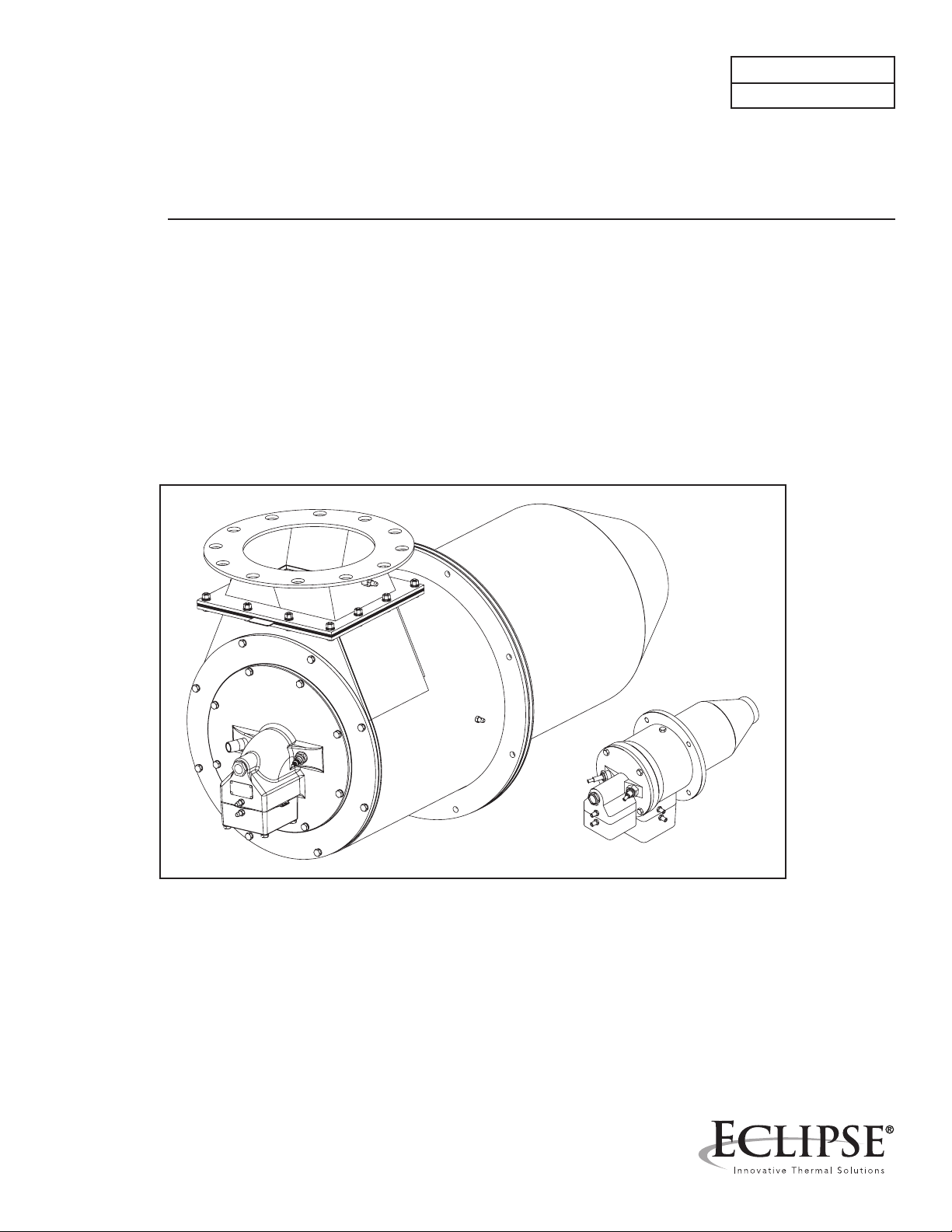
Eclipse ThermJet
Burners
Models TJ0015 – TJ2000
Version 2

Copyright
Copyright 2007 by Eclipse, Inc. All rights reserved worldwide.
This publication is protected by federal regulation and shall not
be copied, distributed, transmitted, transcribed or translated
into any human or computer language, in any form or by any
means, to any third parties, without the express written consent
of Eclipse, Inc.
In accordance with the manufacture’s policy of continual product improvement, the product presented in this brochure is
subject to change without notice or obligation.
DisClaimer NotiCe
liability aND
WarraNty
The material in this manual is believed adequate for the intended use of the product. If the product is used for purposes other
than those specied herein, conrmation of validity and suitability must be obtained. Eclipse warrants that the product itself
does not infringe upon any United States patents. No further
warranty is expressed or implied.
We have made every effort to make this manual as accurate
and complete as possible. Should you nd errors or omissions,
please bring them to our attention so that we may correct
them. In this way we hope to improve our product documentation for the benet of our customers. Please send your corrections and comments to our Marketing Communications
Manager.
It must be understood that Eclipse’s liability for its product,
whether due to breach of warranty, negligence, strict liability,
or otherwise is limited to the furnishing of replacement parts
and Eclipse will not be liable for any other injury, loss, damage
or expenses, whether direct or consequential, including but not
limited to loss of use, income, or damage to material arising in
connection with the sale, installation, use of, inability to use, or
the repair or replacement of Eclipse’s products.
Any operation expressly prohibited in this Guide, any adjustment, or assembly procedures not recommended or authorized
in these instructions shall void the warranty.
Eclipse ThermJet Design Guide No. 205, 3/5/07

About this manual
auDieNCe
thermJet DoCumeNts
This manual has been written for people who are already
familiar with all aspects of a nozzle-mix burner and its add-on
components, also referred to as “the burner system.”
These aspects are:
Design/selection
•
Use
•
Maintenance.
•
The audience is expected to have had experience with this
kind of equipment.
Design Guide No. 205
This document
•
Data Sheet No. 205-1 through 205-13
Available for individual TJ models
•
Required to complete design calculations in this guide
•
Installation Guide No. 205
Used with Data Sheet to complete installation
•
Price List No. 205
Used to order burners
•
relateD DoCumeNts
EFE 825 (Combustion Engineering Guide)
•
Eclipse bulletins and Info Guides:
•
610, 710, 720, 730, 742, 744, 760, 930
Purpose
The purpose of this manual is to make sure that the design of a
safe, effective and trouble-free combustion system is carried out.
Eclipse ThermJet Design Guide No. 205, 3/5/07
3
DoCumeNt
CoNveNtioNs
There are several special symbols in this document. You must
know their meaning and importance.
The explanation of these symbols follows below. Please read it
thoroughly.
Danger:
Indicates hazards or unsafe practices which
WILL result in severe personal injury or even
death.
Only qualied and well trained personnel are
allowed to carry out these instructions or procedures.
Act with great care and follow the instructions.
Warning:
Indicates hazards or unsafe practices which could
result in severe personal injury or damage.
Act with great care and follow the instructions.
hoW to get help
Caution:
Indicates hazards or unsafe practices which could result in
damage to the machine or minor personal injury, act carefully.
Note:
Indicates an important part of the text. Read thoroughly.
If you need help, contact your local Eclipse representative. You
can also contact Eclipse at:
1665 Elmwood Rd.
Rockford, Illinois 61103 U.S.A.
Phone: 815-877-3031
Fax: 815-877-3336
http://www.eclipsenet.com
Eclipse ThermJet Design Guide No. 205, 3/5/07

Table of contents
1
2
3
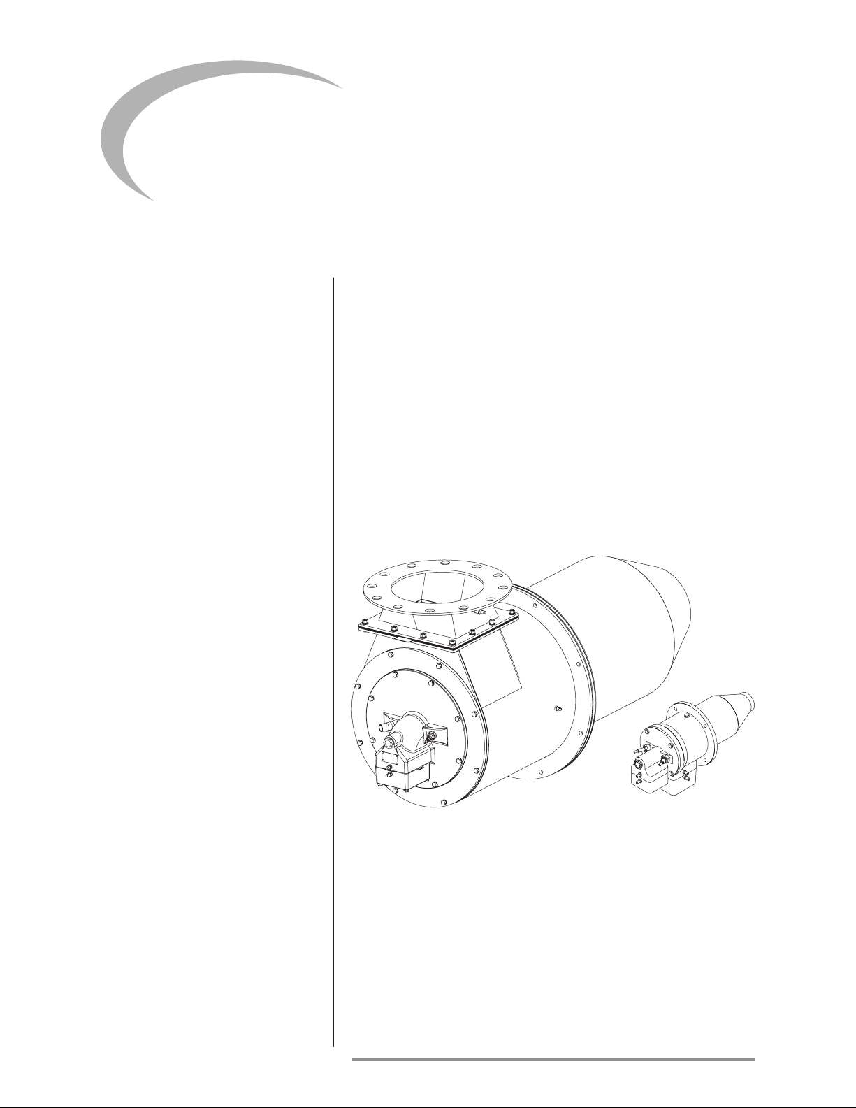
Introduction
Product Description .......................................................................... 6
Figure 1.1 The ThermJet Burner ..................................................... 6
Safety
Introduction ........................................................................................ 7
Safety ..................................................................................................... 7
Capabilities ......................................................................................... 8
Operator Training ............................................................................... 8
Replacement Parts ............................................................................. 8
System Design
Design ................................................................................................... 9
Step 1: Burner model selection ....................................................... 9
Step 2: Control Methodology .......................................................... 10
Figure 3.1: Modulating gas & air:
On-ratio control or excess air @ low re ............................ 12
Figure 3.2: Modulating gas with xed-air control ...................... 13
Figure 3.4: High/Low gas with xed-air control ........................ 15
Step 3: Ignition System ..................................................................... 16
Figure 3.5: Bypass start gas circuit schematics ........................... 17
Step 5: Combustion Air System: Blower
and air pressure switch ............................................................. 19
Table 3.1: Required calculation information ................................ 20
Table 3.2: Fuel gas heating values ................................................... 20
Example blower calculation ............................................................. 21
Step 6: Main gas shut-off valve train .............................................. 22
Step 7: Process Temperature Control System ............................ 22
Appendix
Conversion Factors ........................................................................... 23
Key to System Schematics ............................................................... 24
Eclipse ThermJet Design Guide No. 205, 3/5/07
5
Introduction
1
proDuCt
DesCriptioN
The ThermJet is a nozzle-mix burner that is designed to re an
intense stream of hot gases through a combustor using ambient
combustion air.
The high velocity of the gases improves temperature uniformity,
product quality and system efciency.
The ThermJet burner comes in two types:
High Velocity (HV)
•
Medium Velocity (MV)
•
The gas velocity can be as high as 500 ft/s for the High Velocity
burner, and 250 ft/s for the Medium Velocity burner.
Figure 1.1 The ThermJet Burner
Eclipse ThermJet Design Guide No. 205, 3/5/07
Safety
2
iNtroDuCtioN
safety
Important notices about safe burner operation will be found in
this section. Read this entire manual before attempting to start
the system. If any part of the information in this manual is not
understood, then contact your local Eclipse representative or
Eclipse, Inc. before continuing.
Danger:
The burners covered in this manual are designed
to mix fuel with air and burn the resulting mixture. All fuel burning devices are capable of
producing res and explosions when improperly
applied, installed, adjusted, controlled or maintained.
Do not bypass any safety feature. Fires and explosions can be caused.
Never try to light the burner if the burner shows
signs of damage or malfunctioning.
Warning:
The burner is likely to have HOT surfaces. Always wear protective clothing when approaching
the burner.
Note:
This manual gives information for the use of these burners
for their specic design purpose. Do not deviate from any instructions or application limits in this manual without written
advice from Eclipse, Inc.
Eclipse ThermJet Design Guide No. 205, 3/5/07
7

safety (CoNtiNueD)
Warning:
Eclipse products are designed to minimize the
use of materials that contain crystalline silica.
Examples of these chemicals are: respirable
crystalline silica from bricks, cement or other
masonry products and respirable refractory
ceramic bers from insulating blankets, boards,
or gaskets. Despite these efforts, dust created by
sanding, sawing, grinding, cutting, and other construction activities could release crystalline silica.
Crystalline silica is known to cause cancer, and
health risks from the exposure to these chemicals vary depending on the frequency and length
of exposure to these chemicals. To reduce this
risk, limit exposure to these chemicals, work in a
well-ventilated area and wear approved personal
protective safety equipment for these chemicals.
Capabilities
operator traiNiNg
replaCemeNt parts
Adjustment, maintenance and troubleshooting of the mechanical
and the electrical parts of this system should be done by qualied personnel with good mechanical aptitude and experience
with combustion equipment.
The best safety precaution is an alert and competent operator. Thoroughly instruct new operators so they demonstrate
an adequate understanding of the equipment and its operation.
Regular retraining must be scheduled to maintain a high degree
of prociency.
Order replacement parts from Eclipse only. Any customer-supplied valves or switches should carry UL, FM, CSA,CGA and/or
CE approval where applicable.
Eclipse ThermJet Design Guide No. 205, 3/5/07
 Loading...