

Page 1
Instruction Manual 904
7/24/06
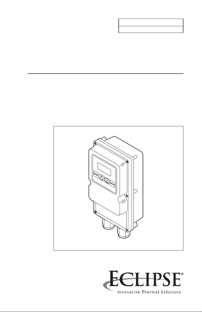
Eclipse Programmable
Rotary Actuator
Series PRA6
Version 1
Page 2

Copyright
DisClaimer notiCe
liability anD
warranty
Copyright 2006 by Eclipse, Inc. All rights reserved
worldwide. This publication is protected by federal
regulation and shall not be copied, distributed,
transmitted, transcribed or translated into any
human or computer language, in any form or
by any means, to any third parties, without the
express written consent of Eclipse, Inc.
In accordance with the manufacturer’s policy of
continual product improvement, the product
presented in this brochure is subject to change
without notice or obligation.
The material in this manual is believed adequate for
the intended use of the product. If the product is
used for purposes other than those specied herein,
conrmation of validity and suitability must be
obtained. Eclipse, Inc. warrants that the product itself
does not infringe upon any United States patents.
No further warranty is expressed or implied.
We have made every effort to make this manual
as accurate and complete as possible. Should
you nd errors or omissions, please bring them
to our attention so that we may correct them.
In this way we hope to improve our product
documentation for the benet of our customers.
Please send your corrections and comments to
our Marketing Communications Manager.
It must be understood that Eclipse's liability for
its products, whether due to breach of warranty,
negligence, strict liability, or otherwise, is limited
to the furnishing of rotary actuator replacement
parts and Eclipse will not be liable for any other
injury, loss, damage or expenses, whether direct
or consequential, including but not limited to loss
of use, income of, or damage to material arising
in connection with the sale, installation, use of,
inability to use or the repair or replacement of
our products.
2
Eclipse Rotary Actuator Instruction Manual 904-7/24/06
Page 3

About this manual
auDienCe
sCope
aCtuator
publiCations
important notiCes
This manual has been written for the people who
will install the product and the technicians who
work on it. They are expected to have previous
experience with this kind of equipment.
This manual contains essential information for the
proper installation and operation of an Eclipse
Programmable Rotary Actuator.
Instruction Manual No. 904
• This publication.
Data Sheet No. 904
• Lists actuator information including dimensions.
Price Sheet No. 904
• Used to order actuators.
• Read this manual carefully. Make sure that you
understand the structure and contents of this
manual.
• Obey all the safety instructions.
• Do not deviate from any instructions or application limits in this manual without written consent
from Eclipse, Inc.
• If you do not understand any part of the information in this manual, do not continue. Con-
tact your Eclipse sales ofce or Eclipse, Inc.
Eclipse Rotary Actuator Instruction Manual 904-7/24/06
3
Page 4

DoCument
Conventions
There are several special symbols in this document.
You must know their meaning and importance.
The explanation of these symbols follows. Please
read it thoroughly.
Warning:
Indicates hazards or unsafe practices
which could result in severe personal
injury or damage.
Act with great care and follow the instructions.
Caution:
Indicates hazards or unsafe practices which could
result in damage to the machine or minor personal injury.
Act carefully.
Note:
Indicates an important part of the text.
Read the text thoroughly.
4
Eclipse Rotary Actuator Instruction Manual 904-7/24/06
Page 5

Table of Contents
About this manual ................................. 3
Audience ................................................................ 3
Scope ...................................................................... 3
Actuator Publications .......................................... 3
Important Notices ............................................... 3
Document Conventions ..................................... 4
Table of Contents ................................... 5
1
Introduction ................................................ 7
Product Description ............................................ 7
Installation .................................................... 8
2
Introduction .......................................................... 8
Handling and Storage .......................................... 8
Approval of Components ................................... 9
Electrical wiring ................................................ 9
Where to get the standards .......................... 9
Checklist Before Installation .............................. 9
A Note on Safety.................................................. 10
Actuator Mounting .............................................. 11
Mount Actuator to Buttery Valve .................. 12
Actuator Wiring ................................................... 15
Power supply ..................................................... 16
Auxiliary contacts ............................................ 16
Low re wiring ................................................. 16
High re wiring ................................................. 17
Control signal wiring ....................................... 17
Disable settings wiring .................................... 17
Eclipse Rotary Actuator Instruction Manual 904-7/24/06
5
Page 6

Parameter Selection ........................... 21
3
Introduction .......................................................... 21
Low Fire Stop (LF) ............................................... 21
High Fire Stop (HF) ............................................. 22
Control Signal Loss (LO).................................... 22
Low Fire Contact Release (LL) ......................... 23
Low Fire Contact Sense (LS) ............................. 23
High Fire Contact Sense (HS) ........................... 25
High Fire Contact Release (HH) ...................... 26
Manual Position Select ........................................ 26
Signal Input Select ................................................ 27
Auxiliary Contact Select–Normally Closed ...... 27
Auxiliary Contact Select–Normally Open ......... 27
Clockwise Rotation Select ................................. 28
Counterclockwise Rotation Select .................. 28
Examine Setpoints ................................................ 28
Default Setpoints .................................................. 29
Stalled Motor ........................................................ 29
Specications ............................................. 30
4
Dimensions ............................................................ 31
Keypad orientations ............................................. 32
Maintenance & Troubleshooting 33
5
Introduction .......................................................... 33
Maintenance .......................................................... 33
Monthly Checklist ............................................ 33
Yearly Checklist ................................................ 33
Troubleshooting .................................................... 34
Appendix ........................................................ 35
Table 1: Actuator Parameter Record ............. 35
Table 2: Model Number Conguration ......... 35
6
Eclipse Rotary Actuator Instruction Manual 904-7/24/06
Page 7
Introduction
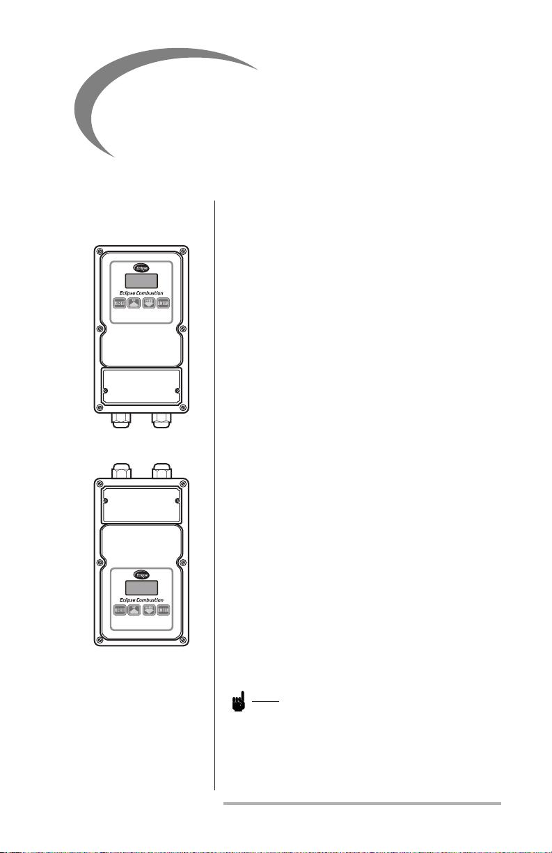
Upright (Standard) Orientation
Inverted Orientation
1
proDuCt
DesCription
The Eclipse Programmable Rotary Actuator is a
keypad-programmable, direct-coupled modulating
motor for use in burner and valve control systems.
It is typically used with an electronic control to regulate a process temperature. The drive shaft of the
actuator connects to a buttery valve stem, which
rotates 90 degrees from minimum to maximum
position.
Actuator features include: solid state electronics;
LED display with membrane keys; 4-20mA, 0-10Vdc
and switch inputs for positioning; and two auxiliary
contacts for position feedback.
The display keypad provides indication of position
and direction of travel, and allows local manual
positioning control. It also provides access to set
the following parameters: minimum and maximum
travel positions; actuation position for the auxiliary contacts; and direction of rotation.
The display keypad can be ordered in four positions: upright (standard) for vertical mounting
with the wiring connections at the bottom; 90
degrees (RH) for horizontal mounting with the
wiring connections to the right; 270 degrees (LH)
for horizontal mounting with the wiring connections to the left; or inverted for mounting with
the wiring connections at the top. (See page 32
for additional keypad orientation illustrations.)
The keypad orientation cannot be changed in the
eld.
Note:
These instructions apply to heating applications
where a maximum output from the tempera-
ture controler drives a buttery valve up to its
maximum ow position.
Eclipse Rotary Actuator Instruction Manual 904-7/24/06
7
Page 8
Installation
2
introDuCtion
hanDling anD
storage
In this section you will nd the information and
instructions that you need to install the actuator.
Caution:
Installation and maintenance must conform
with the National Electrical Code and all other
national and local codes and authorities having
jurisdiction. The actuator must be installed by a
qualied, licensed technician.
Handling
1. Make sure that the area is clean.
2. Protect the actuator from the weather, dam-
age, dirt and moisture.
3. Protect the actuator from excessive temperatures and humidity.
4. Take care not to hit or drop the actuator.
Storage
1. Make sure that the actuator is clean and in
good condition.
2. After you have made sure that everything is
present and in good condition, keep the actuator in the original package as long as possible.
3. Store the actuator in a cool, clean, dry room.
8
Eclipse Rotary Actuator Instruction Manual 904-7/24/06
Page 9

approval of
Components
Electrical Wiring
All of the electrical wiring must comply with one
of the following standards:
• NFPA Standards 70
• EN60204-1
• the electrical wiring must be acceptable to the
local authority having jurisdiction.
Where to get the
standards
CheCklist before
installation
The NFPA Standards are available from:
National Fire Protection Agency
Batterymarch Park
Quincy, MA 02269
Information on the EN standards, and where to
get the standards is available from:
European Committee for Electrotechnical
Standardization
4, Galerie Ravenstein
B-1000 Brussels, Belgium
Access
Make sure that you install the actuator in such a
way that you have easy access to it for inspection
and maintenance.
Environment
Make sure that the local environment matches
the original operating specications. Check the
following items:
• voltage, frequency and stability of the
electrical power
• humidity, altitude and temperature of air
• presence of damaging corrosive gases in the
air.
Eclipse Rotary Actuator Instruction Manual 904-7/24/06
9
Page 10

PRA6 controlling
Fuel Butterfly Valve
Blower
Burner
Safety Shut-off valves
controlled by
Flame Safeguard
Ratio Regulator
Fuel Flow
Control Valve
Burner
PRA6 Controlling
Air Butterfly Valve
Safety Shut-off Valves
controlled by
Flame Safeguard
Blower
Sensing Line
A Note on Safety
The Eclipse Programmable Rotary Actuator must
be used with an approved listed combustion con-
trol system consisting of a ame safeguard and
safety shut-off valves. The diagrams below illustrate the general arrangement of the typical control schemes. These diagrams do not show all of
the devices that may be required for a complete
control system and are not meant to be used for
construction.
Fixed Air Burner
Ratio Burner
10
Caution:
Use of this product in the European community
shall only be deployed in a manner that meets
the applicable EC directives and laws.
Eclipse Rotary Actuator Instruction Manual 904-7/24/06
Page 11
aCtuator
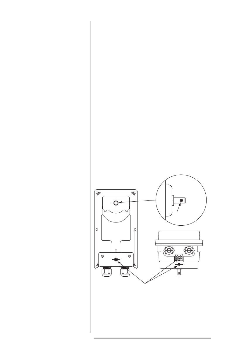
Bottom End View
Mounting
Holes
Shaft Detail
3mm
(0.12”) Dia.
mounting
Depending on your application, please keep the
following in mind when mounting the actuator:
• The actuator housing has three mounting holes,
as shown in Figure 1. The holes are threaded and
use M6 metric screws.
• Mounting this actuator depends on the application; See Data 904 and contact Eclipse, Inc. for
available mounting kits.
• When mounting the actuator, be certain that the
actuator’s drive shaft is properly aligned with the
other shaft to which it will be coupled to avoid
undue lateral stress.
• The actuator’s drive shaft has a 3mm through
hole for a coupler, as shown in Figure 1.
• Provide support for the weight of conduit or
cables into the actuator.
Figure 1 Coupler & Mounting Holes Location
Eclipse Rotary Actuator Instruction Manual 904-7/24/06
11
Page 12

Caution:
Electrical ttings are factory installed to maintain seal and must not be altered. Use only
factory supplied ttings assembled as shown
on Data 904.
Caution:
Prevent water from condensation owing into
the actuator housing through the wiring conduits. Keep conduits oriented such that gravity
will cause water to ow away from the actuator or provide a watertight seal in the conduit
near the actuator.
Warning
Local regulations may require guards
and/or warnings when connecting the
actuator to a component with linkage
that could cause nger pinching. The
actuator stall torque is at least 3.9 n-m
(35 lb-in).
mount aCtuator
to butterfly
valve
12
Warning
Do not attempt to mechanically force
the PRA6 shaft to rotate
Determine if the buttery valve (BV) has
1.
unrestricted full rotation or if it has physical
stops that limit rotation to a specic angle.
Also determine the minimum position, rotation direction to open, and maximum open
position for the BV. The Programmable Rotary
Actuator (PRA) is shipped in its minimum position, clockwise to open, and the part number
shows whether the stroke has been factory
set to either 90 degrees or 75 degrees (see
Table 2 of the Appendix). These settings can
be changed through the keypad. Compare the
BV requirements to the PRA.
Eclipse Rotary Actuator Instruction Manual 904-7/24/06
Page 13

Butterfly Valve
Shutter
Shaft
Slot is in
line with
the shutter
Bolt is
perpendicular
to shutter
Coupling
Note:
The buttery valve rotation direction is viewed
from the shaft end connected to the actuator,
the same view as facing the actuator’s keypad.
The slot at the end of the buttery valve shaft is
parallel to the shutter. When the shaft is rotated
to align the slot to the pipe direction, the valve is
at maximum ow. Eclipse BVs with the beveled
shutter option have a 75-degree stroke. The
minimum positions of these valves physically stop
at about a 15-degree angle when the buttery
shaft is turned fully counter-clockwise. Therefore
the PRA must have its low position set to about
15 to prevent trying to rotate against the physical
stop. Final ne-tuning adjustments to the
minimum position can be made after mounting
the PRA to the BV.
2. If the stroke or rotation comparison does
not match or if you suspect the PRA has
been set differently from the part number,
then provide temporary power to the PRA
before mounting. Refer to the “Power
Supply” heading on page 16. Then refer to
Section 3 (“Parameter Selection,” page 21)
and adjust the settings as follows:
a. Refer to “Clockwise or
Counterclockwise Rotation Select”
to set the rotation direction to
match the BV.
b. Refer to “Low Fire Stop (LF)” to
set the minimum position. Also
reference the note for “Control
Signal Loss (LO)”.
c. Refer to “High Fire Stop (HF)” to set
the maximum position.
d. Check your settings by putting
the PRA in the manual mode (see
Section 3, “Parameter Selection” and
“Manual Position Select”). Drive
the PRA up to the full open position
and note the display and shaft. Then
drive back down to the full closed
position and note the display and
shaft.
Eclipse Rotary Actuator Instruction Manual 904-7/24/06
13
Page 14

3a.
3b.
3c.
4.
5.
6.
7.
3. Install the coupling to the PRA shaft. For
the standard solid coupling with a 3mm
slotted spring pin:
a. Insert the spring pin partially into
the coupling. Insertion may be
easier by rst squeezing the tip
slightly with pliers.
b. Slide the coupling onto the PRA
shaft and align the spring pin hole
in the coupling with the through
hole in the shaft. A view from the
opposite side open hole of the
coupling will assist alignment.
c. Use slip-lock pliers to press the
spring pin through the coupling
and shaft. Make sure the actuator
body is supported and be careful
not to apply excessive stress on
the shaft.
4. Loosely attach the mounting bracket to the
BV. The Eclipse mounting kits include M8
bolts, at washers, and lock washers for
this purpose. Do not tighten at this time to
allow alignment in the next steps.
5. Rotate the BV to its minimum position to
match the position of the PRA. Slide the
PRA with coupling onto the BV shaft and
align to the bracket.
6. Insert the M4 bolt and lock washer through
the coupling hole and thread about 4 turns
into the BV shaft.
7. Adjust the bracket along its slots to bring
the bracket mounting surface up to the
PRA. Also check and keep the alignment of
the BV and PRA shafts. Attach the M6 bolt
and washer through the bracket into the
mounting hole of the PRA (Figure 1), nger
tight only. Also nger tighten the M8 bolts
holding the bracket to the BV.
8. Remove the M4 bolt from the coupling.
Grab the BV shaft with your ngers and see
if the shaft can be turned within the coupling.
If the shaft is very difcult to turn,
14
Eclipse Rotary Actuator Instruction Manual 904-7/24/06
Page 15

8.
9.
then the bracket must be re-aligned as follows:
a. Partially reinsert the M4 bolt
through the coupling.
b. Loosen the M6 and M8 bolts as
required to make small adjustments
to the bracket alignment until the
BV shaft can be turned by nger
within the coupling when the M4
bolt is removed.
c. Finger-tighten the bolts and repeat
step 8.
9. Tighten the M8 bolts to 5 Nm (45 lb-in) and
check if the alignment has shifted as in step
8. Tighten the M6 bolt to 2 Nm (19 lb-in).
Insert and tighten the M4 bolt to 1 Nm (9
lb-in).
10. Make the electrical connections either
temporary or as required by the application
and apply power. Verify for proper and
smooth motion over the full stroke range,
see step 2-d. Correct any abnormalities
before placing the equipment into operation.
Place the PRA into the correct operating
mode (manual or automatic) as required
by the application, Section 3 “Parameter
Selection” and “Manual Position Select” or
“Automatic Signal Input Select.”
aCtuator wiring
Access is through the two electrical connectors at the
end of the actuator. Remove the front coverplate to
access the terminal strips, as shown in Figure 2.
Warning:
Risk of electric shock. Removal of the
cover plate allows access to conductors
carrying hazardous voltages.
Eclipse Rotary Actuator Instruction Manual 904-7/24/06
15
Page 16

Once the front coverplate is removed, the terminal
strip on the left side (P2) is used for the power supply,
and low and high re auxiliary contacts. The terminal
strip on the right side (P1) is used for the control
signal inputs (4-20mA, 0-10V, etc.).
To install a wire into a terminal, rst be sure the ter-
minal is full open. Strip the wire insulation back 1/4"
(6mm), and insert the wire. Hold the wire in place
while tightening the terminal screw. Inspect the
wire for loose strands and gently pull it to ensure a
secure connection. Use only one wire per terminal.
Figure 3 on page 18 shows the wiring diagram for
the actuator, while Figure 4 on page 19 shows a typical application.
Warning:
After wiring, inspect the seal and install
the cover carefully. Make sure cover is
seated properly to seal out water.
Power Supply
Auxiliary Contacts
Low Fire Wiring
Connect the ground wire to P2-G, the neutral
conductor to P2-1, and the “hot” or line voltage
conductor to P2-2. Provide proper circuit protection (fuse or circuit breaker).
The internal contacts are isolated and voltage-free.
Take care not to exceed the contact ratings listed in
the specications table on page 30. These contacts can
be used for position detection. Connect an external
supply to the common terminals, P2-3 and P2-5.
Connect the external low position load to P2-6, and
the external high position load to P2-4.
A switch or voltage-free contact can be wired
between P1-5 (Low Fire) and P1-1 (COM) to
move the actuator to the low re position.
16
Eclipse Rotary Actuator Instruction Manual 904-7/24/06
Page 17

Figure 2 Coverplate & Terminal Connections
Remove these
two screws to
expose terminal
connections at right
High Fire Wiring
Control Signal
Wiring
Disable Settings
Wiring
A switch or voltage-free contact can be wired
between P1-4 (High FIRE) and P1-1 (COM) to
move the actuator to the high re position.
Note:
These digital signals override the 4-20mA and
0-10Vdc analog positioning signals.
Connect a 4-20mA signal positive (+) to P1-2 and
negative (–) to P1-1 (COM). Or alternately connect
a 0-10 Vdc signal positive (+) to P1-3 and negative
(–) to P1-1 (COM). If both signals are connected,
the greater value signal will determine the actuator’s
position.
After setting the parameters according to
Section 3, connect P1-6 (LC) to P1-1 (COM) to
prevent inadvertent parameter changes through
the keypad. With this jumper installed, pressing
the ENTER key will display "LC" and not allow
parameter changes.
Eclipse Rotary Actuator Instruction Manual 904-7/24/06
17
Page 18

Figure 3 Wiring Diagram for Actuator
Com (-)
Input
Contact Outputs
120 or 230 VAC
Power Supply
HF LF
+
–
+
–
4-20mA
0-10V
High Fire
Low Fire
LC
Shield
P1
P2
Earth
Neutral
Line
HF Com
HF Switch
LF Com
LF Switch
G 1 2 3 4 5 6 1 2 3 4 5 6 G
Note:
1. Separate low voltage signal wiring from high voltage signal wiring.
2. Control circuit wires must:
a) meet 90°C (194°F) specication minimum;
b) recommended range from 22 to 16 AWG (.5 to 1.5mm2), and
c) be in accordance with all applicable codes.
3. Insert only one wire per terminal.
4. Provide power supply circuit protection.
5. P2-G and P1-G are internally connected
18
Eclipse Rotary Actuator Instruction Manual 904-7/24/06
Page 19

Figure 4 Typical Application
Sensor
Start
These components relate to burner sequence (not shown);
See “Control Signal Loss (LO)” on page 22.
High Fire
Low Fire
Temperature
Controller
Actuator
L1 GND L2
Power
OnOff
5A Fuse
L1
L2
GND
T/C
+
–
4-20mA
+
–
1
2
1
2
1
1
1
1
P1-2
P1-1
P1-4
P1-5
P2-G
P2-2
P2-1
P2-3
Coil
P2-4
P2-5
P2-6
shaft at
Coil
high position
shaft at
low position
Note:
The following diagram is an example of how to use the actuator’s various inputs and outputs. Some devices shown may be
omitted or changed, depending on your application.
Eclipse Rotary Actuator Instruction Manual 904-7/24/06
19
Page 20

CheCklist after
installation
1. Conrm the alignment and tightness of all
mechanical connections.
2. Inspect the terminal wiring for stray wire
strands that might cause a short circuit. Check
that the wires are properly inserted into the
terminals and are not loose. Reinstall the
terminal cover.
3. Apply power and verify that the stroke motion is smooth over its entire range. Refer
to Section 3, “Parameter Selections,” for any
adjustments.
4. Record the parameter settings for future
reference in Table 1, Actuator Parameter Con-
guration Record, on page 35.
20
Eclipse Rotary Actuator Instruction Manual 904-7/24/06
Page 21

Parameter Selection
1 2
3
4
5 6
3
introDuCtion
low fire stop
(lf)
In this section you will nd the information about the
actuators various selectable parameters, and how they
can be programmed through the keypad.
This parameter sets the minimum shaft travel position:
1. Press the ENTER key; the message “SC” will appear on the display.
2. Press either the UP or DOWN key until the
number “15” appears on the display.
3. Press the RESET key; the message “PG” will appear on the display.
4. Press the DOWN key; the message “LF” will appear on the display.
5. Press either the UP or DOWN key until your
desired number (the desired degree of shaft rotation) appears on the display.
6. Press the RESET key to complete the sequence.
Eclipse Rotary Actuator Instruction Manual 904-7/24/06
21
Page 22

high fire stop
1 2
3
4
5 6
1
2
3
4
5
6
(hf)
This parameter sets the highest shaft travel position:
1. Press the ENTER key; the message “SC” will appear on the display.
2. Press either the UP or DOWN key until the number “15” appears on the display.
3. Press the RESET key; the message “PG” will appear on the display.
4. Press the UP key; the message “HF” will appear on
the display.
5. Press either the UP or DOWN key until your
desired number (the desired degree of shaft rotation) appears on the display.
6. Press the RESET key to complete the sequence.
Control signal
loss (lo)
This parameter sets the position when the analog control signal is zero. It can be used to set a control valve
at some intermediate position above LF for burner
start-up (see Figure 4 on page 19):
Note:
Set LO to the same value as LF if you want the
actuator to drive to the Low Fire Stop position (LF)
when the control signal is zero.
1. Press the ENTER key; the message “SC” will appear on the display.
2. Press either the UP or DOWN key until the number “12” appears on the display.
3. Press the RESET key; the message “PG” will appear on the display.
4. Press the DOWN key; the message “LO” will appear on the display.
5. Press either the UP or DOWN key until your
desired number (the desired degree of shaft rotation) appears on the display.
6. Press the RESET key to complete the sequence.
22
Eclipse Rotary Actuator Instruction Manual 904-7/24/06
Page 23

low fire ContaCt
1 2
3
4
5 6
1 2
3
4
5 6
release (ll)
Note:
Please refer to Figure 5 on page 24 for an
illustration of the next two parameters.
This description of the contact state is for the normally open mode. As the shaft travels from high
to low, the LL parameter sets where the low re
contact opens back up after having closed at the
LS setting. For most applications this value should
be kept at zero (0). Set LF to 0 rst if you need to
set LL to 0. Do not view LL through code 17 after
it is set. Instead, press the RESET key twice to see
all parameters (See p. 28, "Examine Setpoints.")
1. Press the ENTER key; the message “SC” will
appear on the display.
2. Press either the UP or DOWN key until the
number “17” appears on the display.
3. Press the RESET key; the message “PG” will appear on the display.
4. Press the DOWN key; the message “LL” will
appear on the display.
5. Press either the UP or DOWN key until your
desired number (the desired degree of shaft
rotation) appears on the display; this number
must be of lesser value than the desired low
re contact sense (LS) number.
6. Press the RESET key to complete the sequence.
low fire ContaCt
sense (ls)
This description of the contact state is for the normally open mode. As the shaft travels from high
to low, the LS parameter sets where the low re
contact closes. For most applications this value
should be kept at least ve degrees above LF or
LO, whichever is higher.
1. Press the ENTER key; the message “SC” will
appear on the display.
2. Press either the UP or DOWN key until the
number “16” appears on the display.
3. Press the RESET key; the message “PG” will appear on the display. (Continued on page 25)
Eclipse Rotary Actuator Instruction Manual 904-7/24/06
23
Page 24

Figure 5 Auxiliary Contact Positions in Relation to Shaft Rotation
0
o
0
o
90o
LL=10
o
LL
HS HH
LS
CLOSED
OPEN
Low Auxiliary Contact (P2-5 & 6)
Angular Diagram
Angular Diagram
Linear Diagram
Linear Diagram
10o 20
o
30o40o 50o 60o 70o80o 90
o
0o
CLOSED
Actuator Shaft’s Degree of Rotation
OPEN
High Auxiliary Contact (P2-3 & 4)
10
o
20o 30o 40o
Actuator Shaft’s Degree of Rotation
50o60o 70o 80o 90o
A
c
t
u
a
t
o
r
S
h
a
f
t
LS=20
o
Key
Contact Closed
Contact Open
For the settings of note 2,
the low contact is closed
when the shaft is between
10 and 20 degrees.
0
o
90o
HS=75
o
A
c
t
u
a
t
o
r
S
h
a
f
t
HH=85
o
Key
Contact Closed
Contact Open
For the settings of note 2,
the high contact is closed
when the shaft is between
75 and 85 degrees.
Note:
In the following examples:
1) 0°and 90° represent the actuator shaft’s range of travel rather than the
shaft’s alignment (therefore, 0° does not equal vertical and 90° does not
equal horizontal).
2) The operating mode is normally open, but the values LL, LS, HS and HH
have been changed from the default setpoints shown on page 29. The set
values are: LL=10, LS=20, HS=75 and HH=85
24
Eclipse Rotary Actuator Instruction Manual 904-7/24/06
Page 25

4. Press the DOWN key; the message “LS” will
1 2
3
4
5 6
appear on the display.
5. Press either the UP or DOWN key until your
desired number (the desired degree of shaft
rotation) appears on the display; this number
must be of greater value than the desired low
re contact release (LL) number.
6. Press the RESET key to complete the sequence.
Note:
Please refer to Figure 5 on page 24 for an illustration of the next two parameters.
high fire ContaCt
sense (hs)
This description of the contact state is for the
normally open mode. As the shaft travels from
low to high, the HS parameter sets where the
high re contact closes. For most applications this
value should be kept at least 5 degrees below HF.
1. Press the ENTER key; the message “SC” will
appear on the display.
2. Press either the UP or DOWN key until the
number “16” appears on the display.
3. Press the RESET key; the message “PG” will appear on the display.
4. Press the UP key; the message “HS” will appear
on the display.
5. Press either the UP or DOWN key until your
desired number (the desired degree of shaft
rotation) appears on the display; this number
must be of lesser value than the desired high
re contact release (HH) number.
6. Press the RESET key to complete the sequence.
Eclipse Rotary Actuator Instruction Manual 904-7/24/06
25
Page 26

1 2
3
high fire ContaCt
1 2
3
4
5 6
release (hh)
This description of the contact state is for the normally
open mode. As the shaft travels from low to high, the
HH parameter sets where the high re contact opens
back up after having closed at the HS setting. For most
applications this value should be kept at 90. Set HF
to 90 rst if you need to set HH to 90. Do not view
HH through code 17 after it is set. Instead, press the
RESET key twice to see all parameters.
1. Press the ENTER key; the message “SC” will appear
on the display.
2. Press either the UP or DOWN key until the number “17” appears on the display.
3. Press the RESET key; the message “PG” will appear
on the display.
4. Press the UP key; the message “HH” will appear on
the display.
5. Press either the UP or DOWN key until your
desired number (the desired degree of shaft rotation) appears on the display; this number must be
of greater value than the desired high re contact
sense (HS) number.
6. Press the RESET key to complete the sequence.
manual position
seleCt
26
This parameter puts the actuator in the manual positioning
mode. It allows the operator to manually position the shaft
anywhere between low and high re stop settings with the
UP and DOWN keys:
1. Press the ENTER key; the message “SC” will appear
on the display.
2. Press either the UP or DOWN key until the number “05” appears on the display.
3. Press the RESET key to complete the sequence.
Eclipse Rotary Actuator Instruction Manual 904-7/24/06
Page 27

1 2
3
1 2
3
1 2
3
automatiC signal
input seleCt
This parameter takes the actuator out of the manual
positioning mode. The shaft automatically positions
at a point between low and high res according to
4-20mA, 0-10Vdc or LF/HF inputs on the connec-
tor:
1. Press the ENTER key; the message “SC” will
appear on the display.
2. Press either the UP or DOWN key until the
number “06” appears on the display.
3. Press the RESET key to complete the sequence.
auxiliary ContaCt
seleCt–
normally CloseD
auxiliary ContaCt
seleCt–
normally open
This parameter allows the operator to change the
auxiliary contact from the normally open (NO)
default to normally closed (NC):
1. Press the ENTER key; the message “SC” will
appear on the display.
2. Press either the UP or DOWN key until the
number “07” appears on the display.
3. Press the RESET key to complete the sequence.
This parameter allows the operator to return the
auxiliary contact’s default setting to normally open
(NO) if ever changed:
1. Press the ENTER key; the message “SC” will
appear on the display.
2. Press either the UP or DOWN key until the
number “08” appears on the display.
3. Press the RESET key to complete the sequence.
Note:
The next two parameters describe shaft rotation
when facing the keypad.
Warning:
Disconnect shaft coupling before
changing. The shaft will reposition as
such that 0 becomes 90 degrees.
Eclipse Rotary Actuator Instruction Manual 904-7/24/06
27
Page 28

1 2
3
1 2
3
CloCkwise
1 2
3
rotation seleCt
This parameter allows the shaft to travel clockwise when the input signal increases:
1. Press the ENTER key; the message “SC” will
appear on the display.
2. Press either the UP or DOWN key until the
number “10” appears on the display.
3. Press the RESET key to complete the sequence.
CounterCloCkwise
rotation seleCt
examine setpoints
This parameter allows the shaft to travel counterclockwise when the input signal increases:
1. Press the ENTER key; the message “SC” will
appear on the display.
2. Press either the UP or DOWN key until the
number “11” appears on the display.
3. Press the RESET key to complete the sequence.
Pushing the RESET key twice allows the various
setpoints to be examined. Once activated, the
display will indicate a two-letter parameter code
followed by its value in the following sequence:
a. software version;
b. low re stop position (LF);
c. high re stop position (HF);
d. contact signal loss position (LO);
e. low re contact release position (LL);
f. low re contact sense position (LS);
g. high re contact sense position (HS);
h. high re contact release position (HH);
i. manual (C5) or automatic (C6):
j. aux. contact mode N.O. (C8) or N.C. (C7);
k. rotation CW (CO) or CCW (C1)
The display will show each function's setpoint for
two seconds before scrolling to the next one.
28
Eclipse Rotary Actuator Instruction Manual 904-7/24/06
Page 29

Default setpoints
This parameter resets the actuator to the default
setpoints. The default setpoints are as follows:
• Automatic input signal;
• Normally open (NO) contact;
• Clockwise (CW) rotation;
• 0° for LO, or control signal loss position;
• 0° for LF, or low re contact stop;
• 0° for LL, or low re contact release;
• 5° for LS, or low re contact sense;
• 85° for HS, or high re contact sense;
• 90° for HH, or high re contact release, and
• 90° for HF, or high re contact stop.
To reset the parameters to the default setting:
1. Press the ENTER key; the message “SC” will
appear on the display.
2. Press either the UP or DOWN key until the
number “20” appears on the display.
3. Press the RESET key to complete the sequence.
stalleD motor
If the motor is stalled for more than 30 seconds,
the motor will stop and the display will indicate
the percentage (%) sign.
Normal display and operation will resume automatically when the actuator is commanded to
move in the opposite direction from the stall. To
reverse direction while in the automatic mode,
change either the analog input signal, apply a digital
low re or high re input, or change to the manual
mode. In some cases it may be necessary to disconnect the mechanical coupling to the valve.
Eclipse Rotary Actuator Instruction Manual 904-7/24/06
29
Page 30

Specifications
PARAMETER DESCRIPTION
Power Supply 120VAC (+10%, -15%), 50/60 Hz or 230VAC (+10%, -15%), 50/60 Hz
Internal power consumption: 5VA
Operating Temperature
-
20 to +60 °C (0 to 140 °F)
Storage Temperature
-
25 to +65 °C (-10 to 150 °F)
Humidity 5-95% RH noncondensing
Inputs, Analog 4-20mA @ 250Ω impedance; 0-10Vdc @ 200KΩ Impedance
Inputs, Digital (Isolated contacts) Force to high position; force to low position; disable setting codes
Shaft Rotation Adjustable, 0 to 90º maximum.
Minimum Step 1°
Shaft Rotation Direction Selectable: clockwise or counterclockwise
Keypad Orientation Four positions
Display Accuracy ± 1.5°
Position Indicator 9/16" high LED, 0 to 90°
Speed 13 seconds nominal for 90° @ 60Hz
2.3 N-m (20 lb-in)
3.9 N-m (35 lb-in) @ stall
Auxiliary Contact Ratings
Resistive Load: 8A
Inductive Load: 2A
Wiring Connectors Flexible cord connector: 5.8 to 10 mm ( 0.231to 0.394 in.) OD cable
3/8 in. liquid tight conduit
1/2 in. Female NPT adapter
Terminal Connections 0.5 - 1.5 mm2(22 - 16 AWG)
Shipping Weight
1.1 kg (2.5 lb.)
Environment NEMA 4
Torque (Stall Protected)
4
30
Eclipse Rotary Actuator Instruction Manual 904-7/24/06
Page 31

Dimensions
19mm
(0.75")
Front View
Side View
35mm
(1.38”)
146mm
(5.75”)
25mm
(0.98”)
56mm
(2.20”)
6.35mm
(0.25”)
Diameter Shaft
Back View
M6
Threaded
Mounting Hole
12mm Deep
17.47mm
(0.69”)
31.2mm
(1.23”)
164mm
(6.46”)
112mm (4.41")
206mm
(8.11")
74mm
(2.91)
Eclipse Rotary Actuator Instruction Manual 904-7/24/06
31
Page 32

Dimensions (continued)
Keypad Orientation
Upright (Standard) Inverted
RH- 90 degrees LH- 270 degrees
Shaft Detail
4.6mm (0.18”)
36.53mm
(1.44”)
6.35mm
(0.25”)
3mm
(0.12”) Dia.
26.5mm
(1.045”)
Bottom End View
2x M6
Threaded
Mounting Hole
12mm Deep
Holes (2)
19mm (0.75")
each
11mm
(0.43")
27mm
(1.06")
56mm
(2.20")
32mm
(1.26")
10mm
(0.39”)
32
Eclipse Rotary Actuator Instruction Manual 904-7/24/06
Page 33

Maintenance &
Troubleshooting
introDuCtion
This section is divided into two parts:
• The rst part describes maintenance procedures.
• The second part describes troubleshooting
procedures.
5
maintenanCe
Monthly Checklist
Yearly Checklist
Preventative maintenance is the key to a reliable,
safe and efcient actuator. The core of any preventative maintenance program is a list of periodic tasks.
Note:
The monthly and yearly lists are for average
intervals. If your environment is dirty, then the
intervals may be shorter.
1. Inspect the actuator for physical damage to
the housing or display.
2. Inspect the coupling for loose connections.
3. Observe the shaft while moving for smooth
operation.
1. Inspect the actuator for physical damage to
the housing or display.
2. Inspect the coupling for loose connections.
3. Conrm the parameters settings are identical
to those originally selected.
4. Drive the actuator to its full clockwise and
counterclockwise positions and observe the
shaft while moving for smooth operation.
Eclipse Rotary Actuator Instruction Manual 904-7/24/06
33
Page 34

troubleshooting
problem possible Cause solution
No display messages. • No voltage at P2-1 & P2-2. Check power supply.
Actuator will not move • Stalled motor; “oo” message Correct the mechanical
with signal. on display. problem; see “Stalled
Motor” on page 29.
• Actuator is in manual mode. Deselect manual mode;
see “Automatic Signal
Input Select”
on page 27.
• Actuator at low or high re Refer to “Actuator
stop. Mounting” on page 11;
check parameter settings
for low and high res.
• Signal reversed or no signal Check wiring and refer to
connection. Figure 3 on page 18.
Actuator will not move • Manual mode not selected Select manual mode;
with keypad. see “Manual Position
Select” on page 26.
• Defective keypad Call your Eclipse sales
rep.
• External connection to high Check wiring and remove
re input (P1-5 to P1-1) or external connection.
low re input (P1-4 to P1-1).
• Stalled motor; “oo” message Correct the mechanical
on display. problem; see “Stalled
Motor” on page 29.
Displays "LC" • Setting mode disabled. See "Disable Settings
Wiring" on page 17.
34
Eclipse Rotary Actuator Instruction Manual 904-7/24/06
Page 35

Appendix
P R A 6
A- PG11 liquidtite flexible cord connector
B- 3/8" straight liquidtite conduit connecto
r
C- 1/2" Female NPT adapter
1- Standard .... 0
o
o
2- Inverted ...... 180
o
3- RH .............. 90
o
4- LH .............. 270
o
A - 90 stroke
o
D - 75 stroke
A- 120 VAC
B- 230 VAC
Table 1 Actuator Parameter Conguration Record
Code FaCtory your
Parameter SeleCtion abbrev. Setting deFault Setting
Low Fire Stop LF 15 Down 0°
High Fire Stop HF 15 Up 90°
Control Signal Loss LO 12 Down 0°
Low Fire Contact Release LL 17 Down 0°
Low Fire Contact Sense LS 16 Down 5°
High Fire Contact Sense HS 16 Up 85°
High Fire Contact Release HH 17 Up 90°
Manual Position Select [C5] 05 No
Signal Input Select [C6] 06 Yes
Auxiliary Contact Select–
Normally Closed (NC) [C7] 07 No
Auxiliary Contact Select–
Normally Open (NO) [C8] 08 Yes
Clockwise (CW) Rotation Select [C0] 10 Yes
Counterclockwise (CCW)
Rotation Select
Examine Setpoints Reset —
twice
Default Setpoints 20 —
[C1]
11
No
Table 2 Model Number Conguration
Eclipse Rotary Actuator Instruction Manual 904-7/24/06
35
Page 36

904 Instruction Manual 7/24/06
Litho in U.S.A.
 Loading...