


Test Equipment Depot - 800.517.8431
99 Washington Street Melrose, MA 02176
TestEquipmentDepot.com
MT-5211
3-1/2 Digital LCR Multimeter
User’s Manual
st
Edition,
1
©2014 Copyright by Prokit’s Industries Co., Ltd.

OPERATION MANUAL
SUMMARIZE
The instrument is a stable digital multimeter driven by battery. It comes with
28mm high LCD to make reading more clear. Backlight display and overload
protection make it convenient to use .This instrument features multi functions
for measuring DCV, ACV, DCA,ACA, resistance, capacitance, inductance,
diode, transistor, continuity , temperature and frequency. The instrument
utilizes a dual-integral A/D converter as a key feature and is an excellent tool.
It is portable and ideal for lab, factory and field use.
FETY NOTE
SA
The meter meets the standards of IEC1010.
Please read the operation manual carefully before operation.
1. Do not input anything over a range limit.
2. Voltage below 36V is safe. To avoid electric shock, check whether the
test leads are connected correctly, whether the insulation is good when
measuring over 36DCV or 25ACV.
3. Remove the test leads when changing function and range.
4. To select correct function and range, make sure the range limit setting
is correct. Start with higher limits and work down to correct level if
uncertain.
5. Do not operate the meter if battery case and back cover is not properly
fixed.
6. Do not input voltage when measuring resistance.
7. Remove test leads from test point and turn off the power before
replacing battery and fuse.
8. SAFETY SYMBOLS
“
“
“
“
ARACTERISTIC
CH
1 GENERAL
1.1 Display: LCD displaying.
1.2 Max. displaying: 1999(3 1/2digit)auto polarity indication.
1.3 Measuring method: dual slope A/D conversion.
1.4 Sampling rate: approx. 3 times/second.
1.5 Over range indication: the MSD displays “OL” or “-OL”.
1.6 Low battery indication: “
1.7 Operation environment: (0~40)℃,R.H.<80% .
1.8 Power:One
1.9 Size: 189×97.5×35mm
1.10 Weight: approx. 390g(not includes battery).
1.11 Accessories: operation manual, holster, test leads (20A),
”DANGEROUS VOLTAGE EXISTS,
” GND,“ ”DUAL INSULATION
”THE OPERATOR MUST REFER TO THE MANUAL ,
”LOW BATTERY
” appears.
9V 6F22 battery
Thermocouple (Banana type), transistor test socket.
1
2 TECHNICAL
CHARACTERISTIC
2.1 Accuracy:±(a%× rdg+d) at (23±5)℃,R.H.<75%,one year guaranteed
from the production date.
2.2 TECHNICAL DATA
2.2.1 DCV
RANGE ACCURACY RESOLUTION
200mV 100uV
2V 1mV
20V 10mV
200V
±(0.5%+3)
100mV
1000V ±(1.0%+5) 1V
Input resistance: All ranges: 10 MΩ
Overload protection: 250V DV or AC peak value at 200mV
range.1000V DC or AC peak value at other ranges.
2.2.2 ACV
Range Accuracy Resolution
200mV ±(1.2%+3) 100uV
2V 1mV
20V 10mV
200V
±(0.8%+5)
100mV
750V ±(1.2%+5) 1V
Input impedance:All ranges 10MΩ
Overload protection:250V DC or AC peak value at 200mV ,
750V DC or AC peak value at other ranges.
Frequency response: (40-400) Hz for range 200V;
(40-100) Hz for range 750V;
Display: Sine wave RMS (AVG value response).
2.2.3 DCA
RANGE ACCURACY RESOLUTION
2mA 1uA
20mA
±(0.8%+3)
10uA
200mA ±(1.2%+4) 100uA
20A ±(2.0%+5) 10mA
Max. Input volt drop: 200mV;
Max. input current: 20A(the test time should be within 10
seconds)
Overload protection: 0.2A/250V fast-blow fuse, 20A/250V
quick-action fuse for range 20A.
2
2.2.4 ACA
Max measuring voltage drop:200mV.
Max Input current: 20A (less than 10 seconds).
Overload protection:0.2A/250V fast-blow fuse, 20A/250V
quick-action fuse for range 20A.
Frequency response: 40Hz-200Hz.
Display: Sine wave RMS (AVG value response).
2.2.5 RESISTANCE(Ω)
RANGE ACCURACY RESOLUTION
200Ω ±(0.8%+5) 0.1Ω
2KΩ 1Ω
20kΩ 10Ω
200kΩ 100Ω
2MΩ
20MΩ ±(1.0%+15) 10kΩ
2000MΩ
Open voltage: less than 3V.
Overload protection: 250V DC or AC peak value.
NOTE:
1. At 200Ω range, the test leads should be short-circuited, and
measure the lead to lead resistance, then, subtract from the
real measurement.
2. It is normal to display 10MΩ when the test leads shorted in
range 2000MΩ, it will not effect the accuracy and shall be
subtracted from the value measured. For example: The object
resistance is 1000MΩ, the reading value is 1010MΩ, then the
correct value shall be 1010-10=1000MΩ
3. Lagged display of value is normal when measuring
resistance higher than 1MΩ. Please wait until the display is
stable.
RANGE
2mA 1uA
20mA
200mA ±(2.0%+5) 100uA
20A ±(3.0%+10) 10mA
ACCURACY RESOLUTION
±(1.0%+5)
±(0.8%+3)
±(5.0%(reading-
10)+20)
10uA
1KΩ
1MΩ
3

2.2.6 CAPA
CITANCE (C)
RANGE ACCURACY RESOLUTION
20nF 10pF
200nF 100pF
2uF 1nF
20uF
±(2.5%+20)
10nF
200uF ±(5.0%+5) 100nF
Testing frequency: 100Hz
Overload protection: 36V DC or AC peak value
NDUCTANCE (L)
2.2.7 I
RANGE ACCURACY RESOLUTION
2mH 1uH
20mH 10uH
200mH 100uH
±(2.5%+20)
2H 1mH
20H
Testing frequency: 100Hz
Overload protection: 36V DC or AC peak value
2.2.8 TEMPERAT
URE (T)
10mH
RANGE ACCURACY RESOLUTION
(-20~1000)℃ ±(1.0%+4)<400℃
±(1.5%+15)≧400℃
Banana type Thermocouple.
2.2.9 FREQUENCY
(F)
RANGE ACCURACY RESOLUTION
2KHz 1Hz
20KHz 10Hz
200kHz 100Hz
2000kHz 1KHz
10MHz
Input senility: higher than 3.5VPp-p
Overload protection: 250V DC or AC peak value(less than 10
seconds)
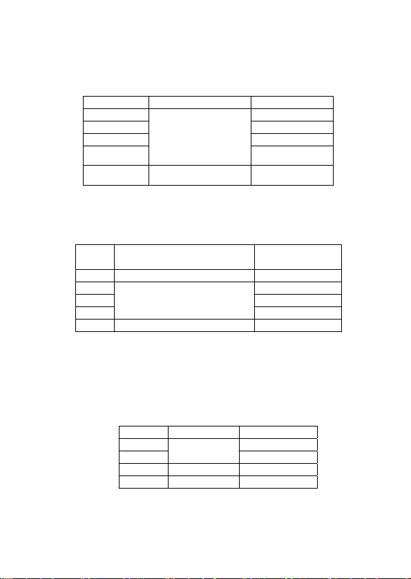
2.2.10
DIODE AND CONTINUITY TEST
±(1.0%+10)
10KHz
Range Displaying value Test condition
The positive DC
Positive voltage
drop of diode
Buzzer sounds ,
the resistance is
less than(70±20)Ω
current is approx.
1mA,negative voltage
is approx. 3V
open voltage is
approx. 3V
4
1℃

Overload protec
Warning: DO NOT input any voltage at this range for safety!
2.2.11 TRANSIST
tion: 250V DC or AC peak value
OR hFE data TEST
Range Displaying value Test condition
hFE
NPN or PNP
0~1000
The base electrode
current is approx
10uA, and Vce is
approx 3V
3 OPERA
TION
3.1 Front panel description
3.1.1 LCD: display the measured
value.
3.1.2 Powe
3.1.3 HOLD: Pressing this key for hold
3.1.4 B/L key: turn on/off hold
3.1.5 DC/AC: select DC/ AC mode
3.1.6 Range knob: selecting
3.1.7 GND. ground, “+” input jack of
3.1.8 “+” pole jack for current lower than 200mA; “-“cathode input for
3.1.9 20A current test jack.
3.1.10 “+” pole jack of voltage, resistance and frequency.
3.2 VOLT
3.2.1 Insert the black test lead to “COM” jack, the red one to V/Ω/Hz
3.2.2 Set the range knob to “V” range, If the measured voltage is
3.2.3 Press DC/AC key to select DC or AC measuring mode.
3.2.4 Apply the test leads to the test point the LCD displays the
NOTE:
a. If LCD displays “OL”, it means over range, set the range knob to
r key: turn on/off the power.
maximum measuring result. LCD
show "PH” icon. Press again this
key turn off data hold and “PH”
icon disappear.
backlight.
measuring function and range.
capacitance (Cx), inductance
(Lx), transistor and temperature.
capacitance (Cx), inductance(Lx), transistor and temperature.
AGE MEASUREMENT
jack.
unsure beforehand, set the range knob to the highest range,
then reduce it gradually until get the highest resolutions
readings.
measured voltage value.
a higher range.
b. Do not input a voltage over 1000V DCA or 750V ACV, the test
5

c. Do not touc
h a high voltage circuit when measuring high voltage.
3.3 CURRENT
MEASUREMENT
3.3.1 Insert the black test lead into “COM” jack, the red one to “mA”
or “20A” jack.
3.3.2 Set the range knob to “A: range, If the measured current is
unsure beforehand, set the range knob to the highest range,
then reduce it gradually until get the highest resolution
readings.
3.3.3 Press DC/AC key to select DC or AC testing mode.
3.3.4 Connect the test leads to the circuit under test, the LCD
displays the measured voltage value.
NOTE:
a. If LCD displays “OL”, it means over range, set the range knob to
a higher range.
b. When measuring current, mA socket should not exceed 200mA,
20A jack should not exceed 20A (test time should be less than
10 sec.), the test leads should be off the test point when
switching the function and range.
3.4 RESISTANCE MEASUREMENT
3.4.1 Insert the black test lead to “COM” jack and the red one to
“V/Ω/Hz” jack.
3.4.2 Set the range knob to a proper resistance range; connect the
test leads across to the resistance being measured.
NOTE:
a. If the resistance value being measured exceeds the max value
of the range selected, LCD displays "OL", set the range knob to
a higher range. When the resistance is over 1MΩ, the meter
may take a few seconds to stabilize. This is normal for high
resistance readings.
b. When input terminal is in open circuit, overload displays.
c. When measuring in-line resistance, be sure that power is off and
all capacitors are discharged completely.
d. Do not input any voltage at this range.
3.5 CAP
ACITANCE MEASUREMENT
3.5.1 Set the range knob to a proper capacitance range and insert
the red test lead to “mA” jack and the black one to “COM” jack
3.5.2 connect the test leads to the capacitor being measured(note:
the polarity of red test lead is “-”).
NOTE:
6

a. If the cap
b. Before measuring, LCD display might not be zero; the residual
c. When measuring large capacitance, LCD may display an
d. Discharge all capacitors completely before capacitance
e. Do not input any volt at this range.
3.6
INDUCTANCE MEASUREMENT
3.6.1 Set the range knob to a proper inductance range and insert the
3.6.2 Connect the test leads to the inductor being measured.
NOTE:
a. If the inductance value being measured exceeds the max value
b. It will get different measuring result when measure inductors are
c. If set the range to 2mH, short test leads to get the inductance
d. Don’t set the range knob to higher range when measuring lower
acitance value being measured exceeds the max value
of the range selected, LCD displays "OL". set the range knob to
the highest range, then reduce it gradually until get the highest
resolutions readings
reading will decrease gradually and should be disregarded.
unstable value due to creep age or breaking.
measurement to avoid damage.
red test lead to “mA” jack and the black one to “COM” jack
of the range selected, LCD displays "OL". set the range knob to
the highest range, then reduce it gradually until get the highest
resolutions readings
different resistance.
then measure and subtract the value from measuring result.
inductor that will cause unstable measuring result.
3.7 TEMPERATURE MEASUREMENT
a. Set range knob “℃”. and insert the thermal couple black test lead to
“mA” jack and the red one to “COM” jack
b. Connect the leads to work-point where wanted to take temperature.
The value will be displayed on LCD (℃).
NOTE:
a. If the temperature being measured exceeds the max value of the
range selected, LCD displays "OL".
b. Don’t change the thermal couple from the other source except
Pro’skit that will affect accuracy.
c. Don’t input voltage form thermal couple when measure
temperature.
3.8 FREQUENCY MEASUREMENT
3.8.1 Apply the test lead or shield to cable to “COM” or ““V/Ω/Hz”
jack.
3.8.2 Switch the knob to frequency range, and connect the test leads
across the signal source or the measured load.
7

NOTE:
a. W
hen input is 10Vrms or less, a reading is possible but maybe
over-range.
b. Shielded cable is recommended when measuring small signals
under noisy conditions.
c. Be careful when measuring high volt circuit.
d. Do not input a voltage over DC 250V or AC peak factor to avoid
damage to the meter.
3.9 Transistor hFE
3.9.1 Turn the range switch to “hFE” position;
3.9.2 Insert test leads into “mA” and “com” jack. Please pay attention
to the polarity, as the “com” for positive and “mA” for negative.
3.9.3 To determine the transistor’s type,NPN or PNP,insert the
emitting, base and collector electrode into the corresponding
jacks in testing accessory
3.10
DIODE AND CONTINUITY TEST
3.10.1 Insert the black test lead to “COM” jack and the red one to
“V/Ω/Hz” jack (Note: the polarity of red test lead is“+”).
3.10.2 Set the range knob to“
diode being measured, reading is the approximation of the
diode positive volt drop.
3.10.3 Connect the test leads to two points of the measured circuit, if
buzzer sounds, the resistance is lower than approx.(70±20)Ω.
3.11 MAX V
ALUE TEST
Press the “PK HOLD”, LCD displays “PH”, the Max. value on testing is
”range, connect the test leads to the
held on LCD, press it again, the function is cancelled.
O POWER OFF
3.12 AUT
After about (20±10)minutes meter not being used ,it will be power off
automatically and enter into dormant status, and press “POWER”
again for two times to turn on power
3.13 POWER ON/OFF
Press “POWER APO” key for 2 seconds to turn on the power and the
meter is in working mode, Press “POWER APO” key again to turn it
off.
3.14 BACKLIGHT
Press “B/L” key to turn on the backlight. After 10 seconds, the
backlight will be turn down automatically
INDICATION
8

4 MAINTENA
DO NOT tamper with the circuit it’s a precision meter and should only be
serviced by factory personnel.
4.1 Do not operate or store the instrument in high temperature or high
4.2 Use the damp cloth and soft solvent to clean the meter; do not use
4.3 If not operated for a long time, take out the battery.
NCE
humidity place and do not work closed to flammability substance or
explosive or strong magnetic field.
abrasive and alcohol.
4.3.1 When LCD displays “
below:
4.3.1.1 Take out of the holster and drop out the battery case.
4.3.1.2 Take out the battery and replace a new one. It’s better
to use alkaline battery for long time use.
4.3.1.3 Fix the battery case and replace the holster.
4.3.2 Replacing fuse
Please use the same type and specification fuse as
replacement.
” symbol, replace the battery as
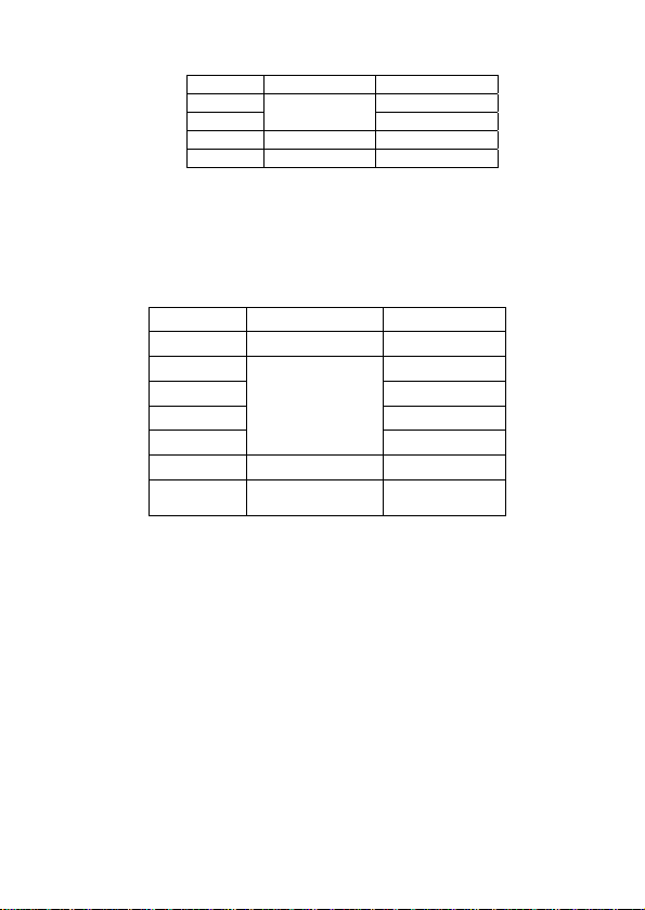
5 TROUBLE SHOOTING
If the meter does not work properly, check the meter as follows:
CONDITIONS WAY TO SOLVE
NO DISPLAYING
●Power is off
●Replace battery
symbol displays ●Replace battery
NO CURRENT INPUT ●Replace fuse
BIG ERROR ●Replace battery
9

MT-5211
3-1/2 LCR 數位電錶使用手冊
一. 產品概述
MT- 5211 3-1/2 LCR 電錶是一台性能穩定、可靠性高的電池驅動數位萬用電
錶。它採用了 28mm 字高的 LCD 顯示器,擁有背光顯示及超載保護功能,更
方便使用者操作。
該儀器具有測量 DCV、ACV、DCA、ACA、電阻、電容、電感、二極體、電
晶體三極管、通斷測試、溫度及頻率等參數和峰值保持功能,採用雙積分A / D
轉換的核心處理器,是一台性能優越的工具儀錶,適合在實驗室、工廠、家庭
使用者的理想工具。
二. 安全注意事項
該儀錶的設計符合 IEC1010 標準。
操作之前,請先閱讀安全注意事項。
1. 測量電壓時,請勿輸入超過直流 1000V 或交流 750V 有效值的極限電壓。
2. 電壓低於 36V 為安全電壓,當測量電壓高於 36V DC/25V AC,請檢查連
接測試錶棒是否可靠接觸、正確連接、絕緣良好,以避免觸電。
3. 改變功能和測量範圍時,測試錶棒應離開測試點。
4. 謹防誤操作,選擇正確的功能和量程,該電錶雖然有全量程保護功能,
但為了安全起見,請你多加注意。
5. 測量電流時,請勿輸入超過 20A 的電流;
6. 安全符號
“
”存在危險電壓, “ ”接地 “” “雙絕緣
“
”必須參照說明書“ “ ”電池電量低
三. 技術指標
1. 一般規格
顯示方式:液晶屏顯示
最大顯示:1999(3 1 /2),自動極性指示
測量方法:雙斜率積分 A / D 轉換器
採樣速率:約 3 次/秒
超量程顯示:最高位顯示 “OL”
10

電池電量低:
工作環境:溫度(0~ 40)℃,濕度< 80% RH
電源:9V(6F22 或同等型號)
尺寸:189*97*35mm (長*寬*高)
重量:大約 390 克(不包括電池)
配件:使用說明書一本,測試錶棒(20A)一對,防震套一個,溫度探頭一
副,電晶體測試座一個
2 電氣規格:
2-1 準確度: ±(讀數 x a%+最低有效位),保證準確度環境︰(23±5)℃,相
對濕度 75%.
2-2 直流電壓 (DCV):
輸入阻抗:所有量程 10MΩ
超載保護:200mV 量程為 250V 直流或交流峰值
其餘為 1000V 直流或交流峰值
2-3 交流電壓(ACV)
輸入阻抗:所有量程為 10MΩ
超載保護:200mV 量程為 250V 直流或交流峰值
其餘為 1000V 直流或交流峰值
頻率回應: 200V 以下量程:40Hz-400Hz,750V 量程 40-100Hz
顯示:正弦波有效值(平均值回應)
”
“
量程 準確度 分辨力
200mV 100uV
2V 1mV
20V 10mV
200V
1000V ±(1.0%+5) 1V
量程 準確度 分辨力
200mV ±(1.2%+3) 100uV
2V 1mV
20V 10mV
200V
750V ±(1.2%+5) 1V
±(0.5%+3)
100mV
±(0.8%+5)
100mV
11

2-4. 直流電流 (DCA)
量程 準確度 分辨力
2mA 1uA
20mA
±(0.8%+3)
200mA ±(1.2%+4) 100uA
20A ±(2.0%+5) 10mA
最大測量電壓降:200mV 的範圍
最大輸入電流:20A(不超過 10 秒)
超載保護:20A 以下量程:0.2A/250V 速熔保險絲
20A 量程:為 20A/250V 即溶保險絲
10uA
2-5. 交流電流(ACA)
量程 準確度 分辨力
2mA 1uA
20mA
±(1.0%+5)
10uA
200mA ±(2.0%+5) 100uA
20A ±(3.0%+10) 10mA
最大測量電壓降:200mV 的範圍
最大輸入電流:20A (不超過10 秒)
超載保護:20A 以下量程:0.2A/250V 速熔保險絲
20A 量程:為 20A/250V 即溶保險絲
頻率回應:40Hz-200Hz
顯示:正弦波有效值(平均值回應)
2-6. 電阻 (Ω)
量程 準確度 分辨力
200Ω ±(0.8%+5) 0.1Ω
2KΩ 1Ω
20kΩ 10Ω
200kΩ 100Ω
2MΩ
±(0.8%+3)
1KΩ
20MΩ ±(1.0%+15) 10kΩ
2000MΩ ±(5.0%(reading-10)
+20)
1MΩ
超載保護:250V 直流或交流峰值
開路電壓:小於 3V
注意:a.在使用 200Ω 量程時,應先將錶棒短路測得引線阻抗,然
後在實測質中減去引線阻抗.
b.2000MΩ 量程表筆短路是顯示 10MΩ,這是正常現象,不
12

影響測量的準確度,實測時應該減去,讀數反應緩慢屬正
2-7. 電容 (F)
測試頻率 100Hz
2-8. 電感 (L)
測試頻率 100Hz
2-9. 溫度(T)
熱電偶
2-10 頻率 (Hz)
常現象,請在顯
量程 準確度 分辨力
20nF 10pF
200nF 100pF
2uF
20uF 10nF
200uF
過載保護:36V 直流或交流峰值
量程 準確度 分辨力
2mH 1uH
20mH 10uH
200mH 100uH
2H 1mH
20H
過載保護:36V 直流或交流峰值
量程 準確度 分辨力
(-20~1000)℃
20KHz 10Hz
200kHz 100Hz
2000kHz 1KHz
10MHz
輸入靈敏度:大於 3.5V Vpp 值
過載保護:250V 直流或交流峰值(少於 10 秒)
±(1.0%+4)<400℃
±(1.5%+15)≧400℃
量程 準確度 分辨力
2KHz 1Hz
示值穩定後再讀數
±(2.5%+20)
±(5.0%+5)
±(2.5%+20)
±(1.0%+10)
1nF
100nF
10mH
1℃
10KHz
13

2-11. 二極體
及通斷測試
量程 準確度 分辨力
正向直流電流約
二極體正向壓降
1mA. 反向電壓
約 3V.
蜂鳴器發出
測試兩點電阻低
長聲,
開路電壓約 3V
於 (70±20)Ω.
過載保護:250V 直流或交流峰值
警告:為了安全,在此量程請勿輸入電壓
2-
12. 晶體三極管 hFE 參數測試
量程 測試範圍 測試條件
hFE
NPN or PNP
0~1000
基極電流約 10uA,
Vce 約為 3V
四. 使用方法
A. 操作面板說明
1. 液晶顯示器︰顯示
:
測量值和單位
2. 電源開關:開啟或關閉電源
3. PK HOLD 讀數保持開關: 按下此功
能鍵,將儀錶當前所測最大數值保
持在液晶顯示器上並出現"PH"符
合,再次 按下, “PH"符號顯示,
退出讀數保持功能狀態
4. B/L 背光開關:按下開啟背光,約 5
秒後 自動關閉
5. DC/AC 鍵:選擇 DC/AC 工作方式
6. 旋鈕開關:用於改變測量功能及量
程
7. 公共地及電容、電感、電晶體測試
座、溫度正極輸入端
8. 小於 200mA 電流測試插座正極端及電容、電感、晶體測試座、溫
度負極輸入端
9. 20A 電流測試插座
10. 電壓、電阻及頻率測試插座
B. 電壓測量:
1. 將黑色測試錶棒插入“ COM ”插孔,紅錶棒插入“ V/Ω/Hz ”插孔。
2. 將旋鈕開關轉至 DCV 或 ACV 量程上,如果被測電壓大小未知,
14

3. 測量直流電壓時
流電壓時,使"DC/AC"鍵按下置 AC 測量方式
4. 將測試錶棒接觸測試點,LCD 即顯示被測電壓值; 測量直流電壓
顯示時,紅色表棒所接觸該點電壓極性為正極。
注意事項:
1. 如果 LCD 顯示“OL ”,表明已超過量程範圍,需將量程轉至高一
2. 不要測量超過 1000V 以上直流或750V 以上交流電壓,轉換功能
3. 注意測量高電壓電路時,應避免觸及高壓電路。
C. 電流測量:
1. 將黑色錶棒插入“ COM ”插孔,紅錶棒插入“mA”或“20A ”插孔中。
2. 將功能開關轉至 DC 或 AC mA/A 檔,如果被測電流大小未知,應
3. 測量直流電流時,使"DC/AC"鍵彈起置 DC 測量方式;測量交
4. 將儀錶的錶棒串聯接入被測電路上,LCD 即顯示被測電流值,測
注意事項:
1. 如果 LCD 顯示“OL ”,表明已超過量程範圍,需將量程轉至高一
2. 測量電流時,”mA”孔不應超過 200mA, ”20A”孔不應超過 20A ,(測
D. 電阻測量:
1. 將黑色錶棒插入“ COM ”插孔,紅錶棒插入“ V/Ω/Hz ”插孔。
2. 設量程開關轉到電阻量程上。將紅,黑錶棒跨接在被測電阻上。
注意事項:
1. 如果電阻值超過所選量程,範圍液晶顯示幕上顯示“OL”,這時需
2. 當輸入端開路時,則顯示“ OL ”狀態。
3. 量測電路中的電阻時,要確認被測電路中所有電源已關閉而所有
4. 請勿在電阻量程內輸入電壓。
5. 測量電阻 1MΩ 以上時,儀錶可能需要幾秒鐘的穩定,這是正常
E. 電容測量:
1. 將黑色錶棒插入“ COM ”插孔,紅錶棒插入“mA”插孔。
檔位。
和量程時,錶棒應離開測試點,否則會損壞儀錶。
先選擇最大量程,再逐步減小,直到獲得解析度最高的讀數。
流電流時,使"DC/AC"鍵按下置 AC 測量方式
量直流電流顯示時,紅色表棒所接觸該點電壓極性為正極。
檔位。
試時間小於 10 秒) 轉換功能和量程時,錶棒應離開測試點,否則
會損壞儀錶。
要轉高一檔。
電容都已完全放電才能進行測量。
的。
,使"DC/AC"鍵彈起置 DC 測量方式;測量交
15

2. 設量程開關轉到電
容量程上。將紅,黑錶棒跨接在被測電容的兩
端進行測量,必要時請注意極性,“ COM ”端口為正極端,“mA”
端口為負極端。
注意事項:
1. 如果被測電容超過
所選量程之最大值,液晶顯示幕上只顯示
“OL”,此時應將開關轉高一檔。
2. 在測試電容之前,液晶顯示幕上可能尚有殘留讀數,屬正常現
象,它不會影響測量結果。
3. 大電容檔測量嚴重漏電或擊穿電容時,將顯示一數字且不穩定
4. 請在測試電容容量之前,對電容應充分的放電,以防止損害儀錶。
5. 嚴禁在此檔輸入電壓。
F. 電感測量:
將量程開關置於相應之電感量程上,將測試電感插入“COM”和
1.
“ mA ”插孔
2. 將表筆跨接在被測試電感的兩端進行測量
注意事項:
1. 如果被測電容超過所選量程之最大值,液晶顯示幕上只顯示
“OL”, 此時應將開關轉高一檔。
2. 同一電感量存在不同阻抗時測得的電感值不相同
3. 在使用 2mH 量程時,應先將表筆短路,測得引線電感值,然後
在實測中減去。
4. 測量小電感是,如果用大量程檔位元將會出現顯示不穩定的隨機
現象。
5. 嚴禁在此檔輸入電壓。
G. 溫度測量:
1. 將量程開關
轉到溫度檔上,將熱電偶感測器的冷端(自由端)負極
(黑色插頭)插入"mA"插孔中,正極(紅色插頭)插入"COM"插孔.
2. 將熱電偶感測器的工作端(測試端)置於被測物上面或內部,可直接
從顯示器上讀取溫度值,讀數為攝氏度
注意事項:
1. 當輸入端
開路時,操作環境高於 18℃時顯示環境溫度,低於 18
℃時則顯示非正常溫度
2. 請勿隨意更換測溫感測器,否則將不能保證測量準確度
3. 嚴禁在溫度檔輸入電壓
H. 頻率測量:
1.
將錶棒或遮蔽電纜插入“COM”和“ V/Ω/Hz ”插孔
2. 將量程開關轉到頻率檔上,將錶棒或遮蔽電纜跨接到信號源或被
測負載上.
注意事項:
1. 輸入超過 10V 交流有效值,可以測量但讀數可能超出誤差範圍。
16

2. 在吵雜的環境中,
測量小信號時最好使用遮罩電纜。
3. 測量信號時,避免接觸高電壓電路。
4. 禁止輸入超過 250V 直流或是交流峰值,以防止損害儀錶。
I. 電晶體 hFE:
將量程開關置於"hFE"檔
1.
2. 將電晶體測試座插入“COM”和“ mA”插孔.注意極性,“ COM ”端口
為正極端,“mA”端口為負極端。
3. 確定所測電晶體為 NPN 型或PNP 型,將發射極、基極、集電極
分別插入測試座的相應插孔
J. 二極體及通斷測
試:
1. 連接黑色錶棒插入到“ COM ”插孔,紅錶棒插入“ V/Ω/Hz ”插孔.
(注意紅色錶棒為+)
2. 將量程開關轉至
檔位, 並將紅色錶棒連接到待測試二極管
正極,黑色錶棒連接到二極管負極,讀數為二極管正向壓降的近
似值。
3. 把錶棒連接到待測電路的兩點,如果內置蜂鳴器發出聲音,則兩
點之間電阻低於約(70±20)Ω。
H. 最大值顯示
按下
“PK HOLD”鍵,液晶顯示幕上”PH”符號,當前測試過程中最
大的數據就會保持在 LCD 上; 再次按下該鍵”PH”符號消失,取消最大
值測量功能,恢復正常測量.
I. 自動關機:
當儀錶閒置(20±10)分鐘後,儀錶便自動關閉並進入休眠狀態。若
要重新啟動電源,再按兩次”POWER”鍵,就可重新接通電源。
J. 電源開啟與關閉:
按下”POWER”鍵儀錶開啟電源,進入工作狀態,再按下此鍵儀錶
關閉電源。
K. 背光:
按下
“B/L”鍵開啟背光,約過 10 秒鐘後,背光將自動關閉。
五. 儀錶保養
錶是一台精密的測量儀器,請使用者不要隨意修改內部電路,以免
該儀
發生危險。
1. 保持儀錶乾燥,並注意防塵,防水,防摔。
2. 不宜在高溫高濕、易燃易爆和強磁場環境下存放及使用儀錶。
3. 本儀器宜輕拿輕放,雖然有防震膠套保護,但嚴重跌落依然有可能
損壞內部電路及殼體,影響儀器正常工作及使用。
4. 請使用濕布和溫和的清潔劑清潔儀錶外觀,不要使用研磨劑及酒精
17

5. 如果長時
6. 注意 9V 電池使用情況,當 LCD 顯示“
驟如下︰
6.1 拆下固定電池蓋的螺絲,打開電池蓋。
6.2 取出 9V 舊電池,換上同類型的新電池。雖然任何9V 電池都可
使用, 但為長時間使用,推薦使用鹼性電池。
6.3 蓋上電池蓋,鎖緊螺絲。
7. 更換保險絲,步驟同更換電池,更換保險絲時, 請使用規格,型
用
,應該取出電池,防止電池漏液腐蝕儀錶。
間不使
”時,應該更換電池,步
號相同的保險絲。
六. 故障排除
如果你的儀錶不能正常運作,下面的方法可以幫助你快速解決一般問題,如
果故障仍無法排除,請與維修中心或經銷商聯繫,我們將儘快協助您處理。
故障現象 檢查部位及方法
沒顯示
電源未接通
保持開關
電池失效,請更換
符號出現 電池電力不夠,請更換電池
電流無法測量 保險絲損壞,請更換保險絲
測量誤差大 檢查並更換電池
本說明書如有變
更,恕不通知。
本說明書基本內容正確,若有錯誤、遺漏之處,請與經銷商聯繫。
本公司不承擔由於用戶不正當操作所引起的事故和危害。
本說明書所講述的操作功能外,請勿將產品做其他特殊用途。
18

寶工實業股份有限公司
PROKIT’S INDUSTRIES CO., LTD.
Test Equipment Depot - 800.517.8431
hingto
99 Was
©2014 Prokit’s Industries Co., LTD. All rights reserved 2014001(C)
n Street Melrose, MA 02176
TestEquipmentDepot.com
19
 Loading...