

99 Washington Street Melrose, MA 02176
Phone 781-665-1400 To
ll Free 1-800-517-8431
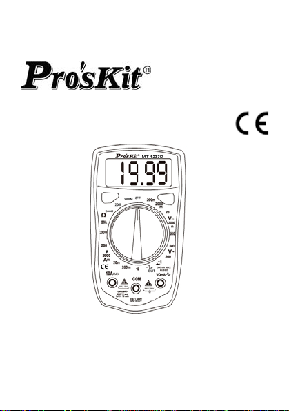
MT-1233C/MT-1233D
3-1/2 Digital Multimeter
’s Manual
User
st
Edition, 2013
1
©2013 Copyright by Prokit’s Industries Co., Ltd.
1

INTRODUCTION
Warning
To avoid electric shock or personal injury, read
"Safety Information" and is Warning and
Precautions" before using the Meter
Safety information
This series meter Comply with IEC 1010-1 CAT I
600V / CAT II 300V overvoltage standards. See
specifications
Use the Meter only as specified in this manual,
otherwise the protection provided by the Meter
may be impaired.
In this manual a Warming identifies conditions
and actions that pose hazards to the user.
A caution identifies conditions and actions that
may damage the meter ort he equipment under
test
International symbols used on the Meter and in
this manual are explained Table
2

Table 1. International Electrical Symbols
AC (Alternating Current)
DC (Direct Current)
AC or DC
Battery
Safety information* Refer to the manual
Earth ground
Fuse
Conforms to European Union directive
Double insulated
WARNING AND PRECAUTIONS
To avoid possible electric shock or personal injury,
and to avoid possible damage to the meter or to the
equipment under test, comply with the following
practices:
Do not use the meter if it is damaged. Before you
use the meter, inspect the case. Pay particular
attention to the insulation surrounding the
connectors.
Inspect the test leads for damaged insulation or
3

Do not use the meter if it operates abnormally.
Protection may be impaired. When in doubt, have
the meter serviced.
Do not operate the meter around explosive gas,
vapor, or dust.
Do not apply more than the rated voltage, as
marked on the meter between terminals or
between any terminal and earth ground.
Before use, verify the meter's operation by
measuring a known voltage.
When measuring current, turn off circuit power
before connecting the meter in the circuit.
When servicing the meter, use only specified
replacement parts. Do not use the Meter in a
manner not specified by this manual or the safety
features of the meter may be impaired.
Use with caution when working above 30V ac rms,
42V ac peak, or 60V dc. Such voltages pose a
shock hazard.
When using the probes, keep your fingers behind
the finger guards on the probes.
Connect the common test lead before you
connect the live test lead. When you disconnect
test leads, disconnect the live test lead first.
Remove the test leads from the meter before you
open the battery door. Do not operate the meter
4

with the battery door or portions of the cover
removed or loosened.
To avoid false readings, which could lead to
possible
Safety Compliance: IEC 61010-1, 2000 CAT I
600V overvoltage standards Do not measure
voltages above 500V in Category installations
Overvoltage installations categories per IEC
61010-1, 2000: The meter is designed to protect
against transients in these categories:
CAT I From high-voltage low-energy sources,
CAT II From equipment supplied from the fixed
CAT III From equipment in fixed equipment
General specifications
Maximum Voltage between any Terminal and
Measurement rata: updates 2-3/sec.
Over range indication: "1' figure only in the display
Automatic negative polarity indication.
The
operating temperature: 0℃~40℃, 0-75% RH.
e.g., electric circuits or a copy machine
installation, e.g., TVs, PCs, portable tools
and household appliances
installations, e.g. installation panels,
feeders and short branch circuits, and
lighting systems in large buildings.
Earth Ground: 1000V
is displayed when the battery voltage
drops below the operating voltage
5
Storage temperature: -10℃~50℃, 0-75% RH.
Power: Single standard 1.5V battery AAAx2
Dimensions: 130L*72W*28H mm
Weight approx: 130g (not including battery)
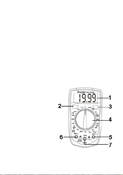
FRONT PANEL DESCRIPTION
1. LCD Display
2. DATA HOLD button
3. BACK LIGHT button
4. FUNCTION AND RANGE SWITCH
This switch is used to select the function and
desired range as well as to turn on the instrument.
To extend the life of this battery, the switch should
be in the "OFF" position when the instrument is
not in use.
5. “VΩmA" JACK
6. "10A" JACK
7. "COM" JACK
SPECIFICATIONS
Accuracies are guaranteed
less than 80%RH
for 1 year, 23℃±5 ℃,
6

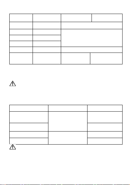
DC VOLTAGE
Range Resolution Accuracy
200mV 100uV
2000mV 1mV
20V 10mV
200V 100mV
500V 1V ±(1.0%+3d)
OVERLOAD PROTECTION: 220V rms AC for
200mV range and 500V DC or 500V rms for all
ranges.
AC VOLTAGE
Range Resolution Accuracy
200V 100mV
500V 1V
RESPONSE: Average responding, calibrated in rms
of a sine wave.
FREQUENCY RANGE: 40Hz ~400Hz
OVERLOAD PROTECTION: 500V DC or 500V rms
for all ranges.
±0.8%+3d
±1.2%+5d
7

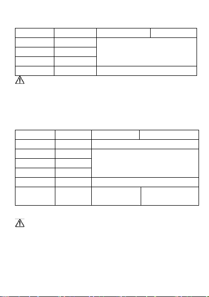
DC CURRENT
Range Resolution Accuracy
2000uA 1 uA
20mA 10 uA
200mA 100 uA
10A 10mA ±(2.5%+5d)
OVERLOAD PROTECTION: 200mA 250V fuse (10A
range unused).
MEASURING VOLTAGE DROP: 200mV
AUDIBLE CONTINUITY
RANGE DESCRIPTION
OVERLOAD PROTECTION: 5 second maximum
220V rms.
WARNING: DO NOT input any voltage at this
range for safety!
SQUARE-WAVE OUTPUT (MT-1233D Only)
RANGE DESCRIPTION
WARNING: DO NOT input any voltage at this
range for safety!
Built-in buzzer sounds if resistance
is less then 30±20Ω
The output of about 50Hz square
wave test signal
±(1.2%+5d)
8
RESISTANCE
Range
200Ω 0.1Ω ±(1.5%+5d)
2000Ω 1Ω
20kΩ 10Ω
200kΩ 100Ω
20MΩ 10KΩ ±(1.0%+5d)
200MΩ 100KΩ - ±[1.0%(rdg
MAXIMUM OPEN CIRCUIT VOLTAGE: 2.3V.
OVERLOAD PROTECTION: 5 seconds maximum
220Vrms.
WARNING: DO NOT input any voltage at
resistance range for safety!
TEMPERATURE (MT-1233C only)
RANGE RESOLUTION ACCURACY
-40℃~150℃ ±(1.0%+3d)
150℃~1000℃
-40℉~302℉ ±(1.0%+4d)
302℉~1832℉
WARNING: DO NOT input any voltage at this
range for safety!
Resolution MT-1233C MT-1233D
±(1.0%+3d)
-l0)+10d]
1℃
1℉
±(1.5%+15d)
±(1.5%+15d)
9

OPERATING INSTRUCTIONS
WARNING
To avoid electrical shock hazard and/or dam
of the Instrument
might exceed 60
Before the use of instrument, inspect test leads,
connectors and probes for cracks, breaks, cracks
in the insulation.
Dangerous voltages may be pres
terminals and ma
To avoid electrical shock or damage to the meter
w
hen measuring resistance or continuity
circuit, make sure the po
turned of
, do not measure volt
0V above earth gr
y not be displaye
f and all capa
ound.
ent at the input
d.
wer to th
citors are discharged.
e circuit is
age
ages that
in a
DC & AC VOLTAGE MEASUREMENT
1. Connect red test lead to "VΩmA" jack, Black
OM" jack.
to "C
2. Set RANGE switch to desired VOLTAGE
if the volt
hand, set switch to the highest range and reduce
it until satisfactory rea
Connect test lead
3.
measured.
Turn on power of
4.
measured voltage value will appear on Digital
Display
age to be measured is not known befor
ding is obt
s to device or circuit being
the device or circuit being
along with the voltage polarity.
ained.
position,
10
lead
e

DC CURRENT MEASUREMENT
1. Red lead lo "VΩmA". Black lead to "COM”(for
measurements between 200mA and 10A connect
red lead to "10A” jack with fully depressed.)
2. RANGE switch to desired DCA position.
3. Open the circuit to be measured and connected
test leads INSERIES with the load in with current
is to measure.
4. Read current value on Digital Display.
5. Additionally,"10A"function is designed for
intermittent use only. Maximum contact time of
the test leads with the circuit is 15 seconds with a
minimum intermission time of seconds between
tests.
RESISTANCE MEASUREMENT
1. Red lead to "VΩmA". Black lead to "COM".
2. RANGE switch to desired OHM position.
3. If the resistance being measured is connected to
a circuit, turn off power and discharge all
capacitors before measurement.
4. Connect test leads LO circuit being measured.
5. Read resistance value on Digital Display.
DIODE MEASUREMENT
1. Red lead to "VΩmA", Black lead to "COM".
2. RANGE switch to "
' position.
11

3. Connect the red test lead to the anode! of the
diode to be measured and black test lead to
cathode.
4. The forward voltage drop in mV will be displayed.
If the diode is reversed, figure "1" will be shown.
TEMPERATURE MEASUREMENT
(MT-1233C only)
1. Connect the K type thermoelectric couple to
"VΩmA" and "COM" jacks.
2. RANGE switch to TEMP position.
3. The display will read Temperature value ℃
AUDIBLE CONTINUITY TEST
1. Red lead to "VΩmA", Black lead to "COM".
2. RANGE switch to “
3. Connect test leads to two points of circuit to be
tested. If the resistance is lower than 30Ω±20Ω,
the buzzer will sound.
TEST SIGNAL USE (MT-1233D only)
1. RANGE switch to "
2. A test signal (50Hz) appears between "VΩmA"
and "COM” jack, the output voltage is approx 3V
p-p with about 50KΩ impedance.
”position.
”position.
12

MAINTENANCE
Beyond replacing batteries and fuses, do not
attempt to repair or service your Meter unless you
are qualified to do so and have the relevant
calibration, performance test and service
instruments. The recommended calibration cycle is
12 months.
To clean the terminals
a) Push the Meter OFF and remove test leads.
b) Shake out any dirt that may be in the terminals.
c) Soak a new swab with isopropyl and work around
the inside of each input terminal
d) Use a new swab to apply a light coat of fine
machine oil to the inside of each terminal.
FUSES TEST
Warning
To avoid electric shock or injury, remove the test
leads and any input signals before replacing the
fuses
1. Turn the rotary switch to 200mA position.
2. Use a multimeter to measure resistance of
"VΩmA" terminal or 10A terminal to COM
terminal.
A good mA terminal or 10A terminal fuse is
indicated by a reading between 0Ω and 10Ω.
If the display is overloaded, replace the fuse and
test again.
If the display shows any other value, have the meter
13

serviced. See "Service and Parts" later in this
manual.
BATTERY AND FUSE REPLACEMENT
1) Battery and fuse replacement should only be
done after the test leads have been disconnected
and power is off.
2) Loosen screws with suitable screwdriver and
remove case bottom.
3) The meter is powered by 1.5V battery (AAAx2).
Snap the battery connector leads to the terminals
of a new battery and reinsert the battery into the
case top. Dress the battery leads so that they will
not be pinched between the case bottom and
case top.
4) The meter is protected by fast action fuse
0.2mA/250V, dimensions is ¢5*20mm.
5) Replace the case bottom and reinstall the three
screws, never operate the meter unless the case
bottom is fully dosed.
ACCESSORIES
User’s manual
Set of test leads(CAT I 600V
K type thermoelectric couple (MT-1233C only)
SERVICE AND PARTS
If the Meter fails, check the batteries and fuses first,
and then review this manual to make sure that you
are operating the Meter correctly
work)
14

一、 概述
MT-1233C/D 儀錶是—種功能齊全,性能穩定,結構新
穎,安全可靠的小型掌上型 3 1/2 位元數位萬用表,可
用於測量交直流電壓、直流電流、電阻、二極體正向
壓降,有些還可以測量溫度和線路通斷,是廣大用戶
隨身攜帶的理想維修工具。本使用說明書包括有關的
安全資訊和警告提示等,請仔細閱讀有關內容,並嚴
格遵守所有的警告和注意事項。
二、 裝箱部件
1.使用說明書 1本
2.測試錶棒 1副
3.溫度探頭(僅限於MT-1233C) 1個
三、 安全操作準則
請注意“警告標識及警告字句"。警告表示對使用者
構成危險。對儀錶或被測設備可能造成損壞的情況或
行動。MT-1233C/D 系列儀錶嚴格遵循電子測量儀器安
全要求以及安全標準 IEC61010 進行設計和生產,符合
雙重絕緣、過電壓標準(CAT I 600V、CAT II 300V)和污
染等級 2 的安全標準。請遵循手冊的使用說明使用儀
錶,否則儀錶所提供的保護功能可能會削弱或失去。
15

1.使用前應檢查錶棒絕緣層應完好,無破損及斷線。
如發現錶棒線或儀錶殼體的絕緣已明顯損壞,或者
您認為儀錶已無法正常工作,請勿再使用儀錶。
2.在使用錶棒時,必須始終確保您的手指放在錶棒手
指保護環之後。
3.不要在儀錶終端及按地之間施加 500V 以上的電
壓,以防電擊和損壞儀錶。
4.被測電壓高於直流 60V 和交流 42V rms 的場合,應
小心謹慎,防止電擊危險。
5.儀錶後蓋沒有蓋好前,嚴禁使用儀錶,否則有電擊
的危險。
6.被測信號不允許超過規定的極限值,以防電擊和損
壞儀錶。
7.嚴禁量程開關在測量中改變檔位,以防損壞儀錶。
8.不允許使用 10A測試端子或用電流檔去測量電壓。
9.必須用同類標稱規格快速熔斷保險絲更換已損壞的
保險絲,確保安全。
10.請勿隨意改變儀錶內部接線,以免損壞儀錶和危
及安全。
11.當液晶顯示器顯示“
電池,以確保測量準確度。
12.不要在高溫,高濕和強電磁場環境中使用儀錶,
尤其不要在潮濕環境中存放儀錶,受潮後的儀
錶,其性能可能變差。
"符號時,應及時更換
16

13.維護保養請使用濕布和溫和的清潔劑清潔儀錶外
殼,不要使用研磨劑或溶劑。
四、 電氣符號
電量
不足
AC
(交流)
雙重絕
緣
AC 或
DC
五、 綜合指標
電壓輸入端子和地之間的最高電壓:500Vrms
10A 端子:無保險絲
mA 端子:F200mA/250V 保險絲
量程選擇:手動
背光功能:手動點亮,延時熄滅
最大顯示:1999,每秒約更新 3 次
極性顯示;自動顯示,負極性顯示“-"符號
過量程顯示:“1"
資料保持功能:液晶顯示幕顯示“H"符號
電池電量不足:液晶屏顯示“
儀錶內使
用電池:l.5V AAA x2
警告
DC
(直流)
蜂鳴器
17
"符號
接地
保險絲
二極體

工作溫度:0℃~40℃ (32℉~104℉)
儲存溫度:-10℃~50℃C (14℉~122℉)
外形尺寸:約為 130L*72W*28/H 毫米
重量:約重 130 克(不包括電池)
外表結構
六、
1.液晶顯示屏
2.數據保持開關
3.背光按鍵開關
4.量程旋鈕
5.電壓,電流,電阻,
溫度測量輸入端
6.10A 電流輸入端
7.公共輸入端
七、按鍵功能
1.資料保持顯示:按下“HOLD"鍵,儀錶液晶顯示
幕上保持顯示當前測量值,再次按鍵則取消此功
能。
2.背光控制:按下背光按鍵即可點亮液晶屏的背光
燈,點亮後約延時 10 秒左右即熄滅。
18

八、 測量操作說明
1.直流電壓及交流電壓測量
a)將紅錶棒插入“VΩmA",黑錶棒插入“COM"
插孔。
b)將功能量程開關置於直流電壓檔位,並將錶棒並
聯到待測電源或負載上。
c)從液晶顯示幕讀取測量結果。
注意:不要測量高於 500V 的電壓,雖然有可能讀
得讀數,但也可能會損壞內部電路及傷害到您。在測
量之前如不知被測量電壓值的範圍時,應將最程開關
置於最高量程檔,根據讀數需要逐步調低測量量程。
當液晶顯示幕只在高位顯示“1"時,說明已超量程,
須調高最程。在每一個量程檔,儀錶的輸入阻抗均為
10MΩ,這種負載效應在測量高阻電路時會引起測量
誤差,如果被測電路阻抗≤10KΩ,誤差可以忽略(0.1%
或更低)。
2.直流電流測量
a)將紅錶棒插入“VΩmA"或 l0A 插孔,黑錶棒插
入“COM"插孔。
b)將功能量程開關置於直流電流檔位,並將錶棒串
聯到待測電源或電路中。
c)從顯示器上讀取測量結果。
注意:如果不知被測電流值的範圍時,應將量程開
關置於高量程檔,根據讀數需要,逐步調低。在 mA
輸入插孔,輸入超載會將內置保險絲熔斷,須及時予
以更換,保險絲尺寸為:Φ5×20mm,電氣規格 F200mA
/250V; 10A 輸入插孔,內部沒有設置保險絲,為了安
全使用,每次測最時間應≤10 秒,間隔時間≥15 分鐘。
19

3.電阻測量
a)將紅錶棒插入“VΩmA"插孔,黑錶棒捅入
“COM"插孔。
b)將功能量程開關置於電阻測量檔位,並將錶棒並
聯到待測電阻上。
c)從顯示器上讀取測量結果。
注意:檢測線上電阻時,為了避免儀錶受損,須確
認被測電路已關掉電源,同時電容已放完電,方能進
行測量。在 200Ω檔測量時,測試錶棒引線會帶來 0.5Ω
左右的測量誤差,為了獲得更精確的讀數,可以將讀
數減去紅、黑兩支表和短路的讀數值,作為最終讀數
值。
4.二極體和通斷測量
a)將紅錶棒插入“VΩmA"插孔,黑錶棒插入
“COM"插孔.
b)將功能量程開關置於二極體測量檔位元,井將紅
錶棒連接到被測二極體的正極,黑錶棒連接到被
測二極體的負極。
c)從顯示器上讀取測量結果。
d)將錶棒連接到待測線路的兩端,如果兩端之間電
阻值低於約 50Ω 時,內置蜂鳴器發聲。
注意:為了避免儀錶損壞,線上測試二極體彰,應
先確認電路已被切斷電源,電容已放完電。用二極體
檔可以測量二極體及其它半導體器件 PN 結的電壓
降,對—個結構正常的矽半導體,正向壓降的讀數應
20

該是 0.6V 左右;反向顯“1"即為開路,此時黑錶棒
對應的極為“+",紅錶棒對應的極為“-"。
5.溫度測量(僅 MT-1233C)
a)將溫度探頭的輸出端(正、負極)分別插入
“VΩmA"與“COM"插孔。
b)將功能量程開關置於溫度測量檔位,並將溫度探
頭的測溫端置於待測物面上或內部。
c)從顯示器上讀取測量結果。
注意:隨機所附溫度探頭為 K 型熱電偶,此類熱電
偶的極限溫度為 250℃。如果要測量更高的溫度,,
須另選購其他型號的溫度探頭。無溫度探頭插入儀錶
時,液晶屏顯示的值為儀錶內部溫度值。不要輸入高
於直流 60V 或交流 30V 的電壓,避免損壞儀錶及傷害
到您。
6.方波試驗信號輸出(僅 MT-1233D)
將功能量程開關置於方波檔,則儀錶從“VΩmA"
與“COM"端之間輸出方波信號。
注意:方波試驗信號其諧波較為豐富,可作為建議
信號源修理音響設備等。頻率約為 50Hz,在接 1MΩ
負載情況下,輸出幅度大於 3V。為了避免儀錶損壞,
嚴禁輸出端(紅錶棒)接觸 10V 以上的電壓。
21

九、 技術指標
準確度:±(a%讀數+字數),保證期為 1 年
環境溫度為:23℃±5℃,相當濕度<75%
1. 直流電壓
量程 分辨力 MT-1233C MT-1233D
200mV 100uV
2000mV 1mV
20V 10mV
200V 100mV
500V 1V ±(1.0%+3d)
輸入阻抗:所有量程為 10MΩ
超載保護:對於 200mV 量程為 250V 直流或交流,其
餘量程為 500V 直流或交流。
2. 交流電壓
量程 分辨力 MT-1233C MT-1233D
200V 100mV
500V 1V
輸入阻抗:約為 5MΩ
頻率回應:40Hz~400Hz
顯示:正弦波有效值(平均值回應)
超載保護:均為 500V 直流或交流
±(0.8%+3d)
±(1.2%+5d)
22
3. 直流電流
量程 分辨力 MT-1233C MT-1233D
2000uA 1uA
20mA 10uA
200mA 100uA
10A 10mA ±(2.5%+5d)
超載保護:F200mA/250v 保險絲
10A 量程無保險絲,測量時間要求≤10 秒,間隔時間
I5 分鐘。
≥
4. 電阻
量程 分辨力 MT-1233C MT-1233D
200Ω 0.1Ω ±(1.5%+5d)
2000Ω 1Ω
20 KΩ 10Ω
200KΩ 100Ω
20MΩ 10KΩ ±(1.0%+5d)
200MΩ 100KΩ -
最大開路電壓︰2.3V
警 告:為了安全在此量程禁止輸入電壓值!
±(1.2%+5d)
±(1.0%+3d)
±[1.0%(讀數
-10d)+10d]
23

5. 溫度(僅 MT-1233C)
量程 分辨力 準確度
-40℃~150℃ ±(1.0%+3d)
150℃~1000℃
-40℉~302℉ ±(1.0%+4d)
302℉~1832℉
溫度感測器:國際標準 K 型(鎳鉻一鎳矽)熱電偶
警 告:為了安全在此量程禁止輸入電壓值!
6. 方波輸出(僅 MT-1233D)
量程 說 明
警 告:為了安全在此量程禁止輸入電壓值!
7. 二極體、通斷測試
功能 量程 備註
二極體 顯示正向壓降近似值
通斷測試 約<50Ω 時蜂鳴器發聲
警 告:為了安全在此量程禁止輸入電壓值!
1℃
1℉
輸出約 50Hz 方波試驗信號,
輸出電阻約 50KΩ
±(1.5%+15d)
±(1.5%+15d)
24

十、 更換電池
如果液晶顯示幕上出現“
更換,請按以下步驟操作:
1. 錶棒離開被測電路,從輸入插孔中拿掉錶棒,並
將儀錶上的旋鈕開關撥到“OFF"檔位以關閉儀
錶電源
2. 用螺絲刀擰開背面電池門的螺絲,將其移走
3. 取出舊電池,更換新的電池(AAA 1.5×2)
4. 重新安裝好電池門,並鎖好螺絲。
十一、保養和維護
警告:
在打開儀錶後蓋之前,應確認電源已關閉和錶棒已
離開被測電路。
清潔儀錶只能使用濕布和少量洗滌劑,切忌用化學
溶劑擦拭表殼。
如發現儀錶有任何異常,應立即停止使用並送維
修。
在有需要對儀錶進行校驗或維修時,請由有資格的
專業維修人員或指定的維修部門維修。
十二、故障排除
如果您的儀錶不能正常工作,下面的方法可以幫助您
快速解決一
般問題。如果故障仍排除不了,請與維修中心或經銷
商聯繫。
"符號,表示電池需要
25

故障現象
沒顯示 電源未接通
符號出現 換電池
顯示誤差大 換電池
檢查部位及方法
換電池
換保險絲
本說明書
本說明書的內容被認為是正確的,若用戶發現有錯
誤、遺漏等,請與生產廠家聯繫
本公司不
危害。
本說明書
途的理由
如有改變,恕不通知;
。
承擔由於用戶錯誤操作所引起的事故和
所講述的功能,不作為將產品用做特殊用
。
26

中國地區產品保固卡
購買日期
店章
公司名稱
聯絡電話
電子郵箱
聯絡地址
產品型號 □ MT-1233C-C □ MT-1233D-C
※ 在正常使用情況下,自原購買日起 12 個月免費維修保證(不含耗
材、消耗品)。
※ 產品保固卡需蓋上店章、日期章,其保固效力始生效。
※ 本卡請妥善保存,如需維修服務時,請出示本卡以為證明。
※ 保固期滿後,屬調整、保養或是維修性質之服務,則酌收檢修工時
費用。若有零件需更換,則零件費另計。
產品保固說明
保固期限內,如有下列情況者,維修中心則得酌收材料成本或修理
費(由本公司維修人員判定):
‧ 對產品表面的損傷,包括外殼裂縫或刮痕
‧ 因誤用、疏忽、不當安裝或測試,未經授權打開產品修理,修改產
品或者任何其他超出預期使用範圍的原因所造成的損害
‧ 因事故、火災、電力變化、其他危害,或自然災難所造成的損害。
非服務保證內容:
‧ 機件本體外之消耗品:如電池...等消耗品
‧ 機件本體之外之附配件:如耳機麥克風,電源供應器,記憶卡,CD
等附配件。
超過保證期限之檢修或服務,雖未更換零件,將依公司保固維修政策
酌收服務費。
服務電話: 0755 83692415/83692986 /83246594/83247554
服務傳真: 0755 83692143
27

99 Washington Street Melrose, MA 02176
Phone 781-665-1400 Toll Free 1-800-517-8431
28
 Loading...