


Safe Operation & Maintenance Instructions
remind you to work safely and to keep this manual on hand.
Rechargeable Cable Cutter
Model # : 902-626
5 Commonwealth Ave5 Commonwealth Ave5 Commonwealth Ave5 Commonwealth Ave
Woburn, MA 01801Woburn, MA 01801Woburn, MA 01801Woburn, MA 01801
Phone 781-665-1400Phone 781-665-1400Phone 781-665-1400Phone 781-665-1400
TollTollTollToll Free 1-800-517-8431Free 1-800-517-8431Free 1-800-517-8431Free 1-800-517-8431
ViVisit us at www.TestEquipmentDepot.com
ATTENTION!
Safe Operation & Maintenance Instructions must be followed.
Thank you for using our products. This manual must be read carefully
prior to operating this product. Special attention should be paid to the
section “Safety Instructions”. Damages and injuries caused by improper
use of this product are NOT included in our warranty. We would like to
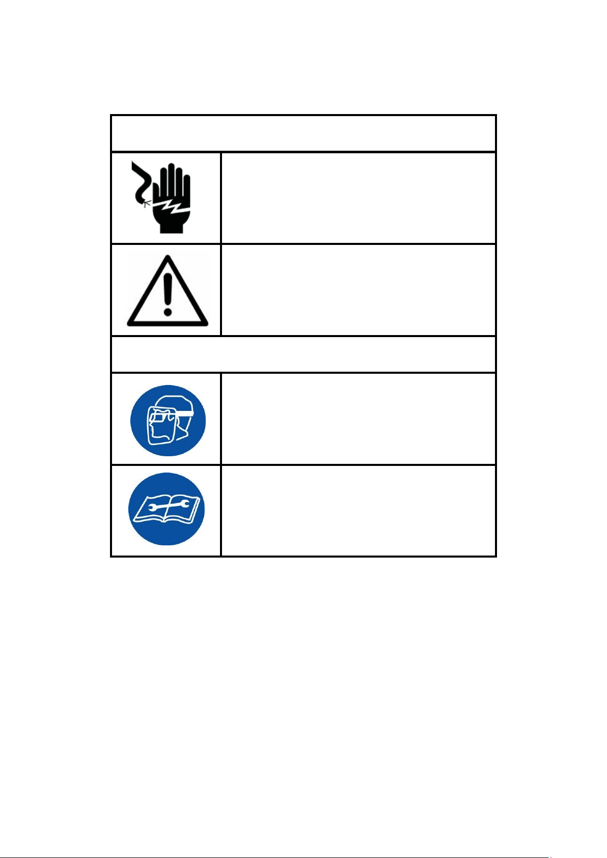
WARNINGS
Read all instructions, warnings, and
or property damage.
Always wear safety goggles when
This product is NOT an insulator and
equipment ratings.
■ Follow ALL instructions to ensure safety.
WARNING
cannot be used near energized
conductors.
Do not use this tool on glass, plastic,
wood or any other materials which
could shatter. Do not exceed
ATTENTION
operating this product. Projectiles or
hydraulic fluid can cause serious
injuries.
cautions carefully. Follow all safety
precautions to avoid personal injury
1

Table of Contents
WARNINGS……..….…………………………………………….1
Table of Contents….…………………………………….………2
Safety Instructions…….……………………………………….3
Product Description.………………………………………...…...4
Operating Instructions..………….………………………………5
Guide Piece Replacement/Battery Charging…………..……..6
Blade Replacement………………...……….…………………...7
Maintenance...……………. …………….…………………8
Troubleshooting……………………….……….………………9
Limited Warranty.……………. … …….………………10
Table of Components………….…………….……………….11
Table of Diagram………………………...…….…….………….12
2

Safety Instructions
Work Area Safety
Personal Safety
3
1
. Keep the area around the tool
clean and free of obstructions.
. Keep the area free of flammables
2
which could ignite while using this
tool.
3
. Children and bystanders should
stay clear of the work area t
ensure safety
lectrical Safety
E
1
. Use only the specified battery
charger for the battery.
. Use only the designated battery
2
1. Stay alert while using this tool to
prevent serious injury. Do not use
under the influence of drugs,
alcohol or medicine.
2. Do not wear loose hair or clothes
that can get caught in the tool
while operating.
o
. To reduce the risk of injury, we
3
ar
non-conductive gloves and
non-skid safety-shoes. Alway
ear protective eyewear.
w
. Make sure the tool switch is
4
s
OFF
or the tool locked before inserting
t
he battery pack.
pack with this tool.
. Do not modify the charger in any
3
way. Ensure the charger matches
the electrical outlet.
4
. Avoid electrical shock. Do not
touch grounded metal conductors
while operating this tool.
5. Do not use this tool in wet
conditions. Store this tool in
lace.
p
. Do not drop or in any way abuse
6
a dry
or disassemble the battery pack
o
r charger.
5
. After servicing the tool, remo
djusting keys or wrenches fr
a
any moving parts of the tool before
use.
6
. Work safely. Maintain your
balance and do not reach while
operating the tool.
ve
om

Product Description: 902-626
■ Specifications:
Height: 12.5 inches (H)
Weight: 6.2 lbs (including battery)
Drive unit: 18V DC Motor
Charger (GS/CE):
■ Accessories:
■ Plastic carrying case
■ 18V Li-ion Battery, 110V
■ Cutting Capacity: (Max. Cable diameter)
■ 2 inches max diameter Copper and Aluminum Only
Battery Specifications Charger Specifications
Input voltage:
120V Single Phase AC
Input frequency: 50-60Hz
Input current: 21.75 VA
Brand: BOSCH
Model No. 902-627
Type: lithium-ion (Li-ion)
Capacity: 4.0 Ah
Output Voltage: 18V
Input Frequency: 50-60 Hz
Model No.: 902-628
Input Voltage: 110V
Charging per battery: Approx.
40min <4.0Ah>
4

Operating Instructions
When the switch to the right, the blade goes backward.
When the switch to the left, the blade goes forward.
1. Install the charged battery by sliding it into the base of the tool handle until it
clicks into place. The battery should be secured and unmoveable.
2
. Take a look at the operation of tool switch syste
here are 3 settings: Move to left (Forward),
T
Center (Neutral), Move to right (Reverse).
When the tool is not in use or is idle,
it should rest in the central position. The
picture on the right shows the cutter Neutral
state.
m.
For Safe
the tool switch in the central position.
5
ty Reasons, when the tool is sitting idly or once you are finished with it, put

Guide Piece Replacement
DO NOT dispose of this battery in a fire or
position.
1. Operate the cutter either forwards or backwards until the moving blade
disengages from the pinion gear and can be pulled free.
2. Remove the battery from the cutter.
3. Use a M2.5-sized Allen wrench to loosen and remove the screw which
secures the gear guide to the moving blade. Install the replacement guide
and tighten the screw. Repeat to replace the second gear guide.
4. Reinstall the battery pack. Feed the the moving blade into the gear
mechanism. Test the new blade movement. If necessary, repeat the
procedure from Step 1.
Battery Charging
1. After removing the battery from the power tool, insert it into the battery
charger. The red indicator will light up and indicate the battery is charging.
2. The green light comes on after approx. 30 mins when the battery is fully
charged.
3. Remove the battery from the charger and install into the handle of the power
tool sliding it into the base of the tool handle until it clicks into place. The
battery should be secured and unmoveable.
4. The charger will not operate effectively if overheated. Allow 10 minutes to
cool down between charges if charging consecutive batteries.
otherwise abuse the battery.
DO NOT short circuit battery output terminals
DO NOT disassemble or modify the battery. This
may lead to short circuiting the battery cells
causing personal injury or damage to the
battery.
Keep your fingers away from edge of the moving
blade when feeding it into the gear mechanism.
The switch may have moved from the NEUTRAL
ATTENTION
6

Blade Replacement
1. Operate the cutter forwards or backwards until the moving blade disengages
from the pinion gear and can be pulled free.
2
. Remove the battery from the cutter.
. Secure the lock nut with a wrench and loosen the shoulder screw with a fl
3
s
crewdriver. Remove the moveable blade from the tool and collect the two
curved washers.
. Use a M2.5-sized Allen wrench to loosen and remove the two screws which
4
at
secures each of the orange gear guides to the moveable blade. Install th
ge
ar guides on the new blade. Screw them into place firmly, with the
lock-washer between the screw head and the gear guide.
5
. Install the new moving blade and assemble the shoulder screw. Position t
t
wo curved washers between the shoulder screw head and moving blade.
Hold the lock nut with the wrench and tighten the shoulder screw.
6
. Reinstall the battery pack. Feed the the moving blade into the gear
mechanism. Test the new blade movement. If necessary, repeat th
e
procedure from Step 1.
e
he
7
Test Equipment Depot - 800.517.8431 - 5 Commonwealth Ave, Woburn, MA 01801
TestEquipmentDepot.com

Maintenance
■ After use, look for burrs or dents in the blade. If burrs exist they can be
removed with a flat grinding stone. Clean, sharp blades will provide better
and safer performance and put less strain on the tool.
■ The plastic housing can be kept clean with a soft soap cloth. Use a
lubricant to clean the blades if necessary.
■ Keep the handle dry and free of grease at all times.
■ Do NOT let the tool drop to the ground or into the carrying case to avaoid
damage to internal parts ot to the plastic housing.
■ Store in a cool, dry area. Do NOT keep this product in places with high
temperatures, high humidity, or direct sunlight.
■ Inform authorized distributors in case of any abnormalities or malfunctions
o
f the product.
■ DO NOT DISASSEMBLE OR ATTEMPT TO REPAIR THIS TOOL.
Disassembly of this tool beyond changing the moving blade and gear
guides will void the warranty.
ATTENTION
DO NOT CUT THROUGH STEEL OR ANY
CONDUCTORS THAT CONTAIN STEEL.
8
.

Troubleshooting
■ The Cable cannot be cut:
A. Tool Blades are worn or damaged. The blades must be replaced. Tools with
worn or damaged blades might cause property damage or even personal
injuries.
B. Applied cable is over-specification. Please check the specification. Th
it breaker will need to be reset.
circu
C. T
he blade might be deformed by uneven distribution after cutting an
off-center cable.
e
■ Charging Lamp does not light up:
A. Dust, etc. has entered the battery cartridge. Clean the battery to remove any
obstructions.
Battery cartridge is overheating. Allow the cartridge to cool be
B.
c
onditioning.
fore
■ Even fully charged, the cutting capacity is reduced:
A. Life of the battery has expired. Replace the battery cartridge with a new
ca
rtridge.
Deterioration of the blade. Replace the blade with a new blade.
B.
■ Tool does not operate:
A. Battery cartridge is not charged. Charge the battery cartridge.
B. The battery contacts are dirty. Clear the battery contacts of dirt or debris.
C. The circuit breaker has been actuated. Push the reset pin to reset the circuit
breaker back to its original position.
D. The OFF lock is not fully depressed. Make sure it is fully depressed and
rese
t the circuit breaker if necessar y.
9

Limited Two-Year Warranty
10
■ Our electronic products are warrantied against defects in materials and
orkmanship for two years.
w
■ This warranty is subject to the following exclusions and limitations:
1
. This warranty does not cover damages to products which are
not installed, operated, used and maintained in accordance with
written instructions.
2. This warranty does not cover products that have been worn out,
damaged by improper storage, damaged or otherwise altered, or
from disassembly or attempted disassembly by parties other than
us or its authorized service representatives.
3. This warranty does not cover damages caused by the use of
components not manufactured or authorized by us, acts of God,
accidents, or use in a manner for which they are not intended.
■ Our liability in all cases is limited to, and shall not exceed, the
urchase price paid. We shall not be liable to any buyer for
p
consequential or incidental damages of any kind.
■ Batteries and cutting blades sold with our products are not covered
y this warranty. Replacements for worn out parts are available for
b
purchase.
■ Receipt of purchase is required for warranty services.
■ If the tool is found to be defective, in our sole judgment, we will
ither repair or replace the defective product or part.
e
■ All revisions in warranty policy and product informations will be
included in future versions of our manuals. Copies of this warranty
are available from the factory upon request.
Test Equipment Depot - 800.517.8431 - 5 Commonwealth Ave, Woburn, MA 01801
TestEquipmentDepot.com

Limited Two-Year Warranty
■ Replace any worn or damaged parts immediately. Do not use
parts not supplied by us.
■ Contact our service representatives to request parts or for
roblems not shown above.
p
■ Do NOT attempt to disassemble or repair the product.
■ Our tools must be serviced by a qualified technician. Contact our
representative for more information.
ATTENTION!
Do not dispose of batteries or electrical appliances as unsorted municipal waste. Use separate
collection facilities*. If electrical appliances are disposed of in landfills or dumps, hazardous
substances can leak into the groundwater and damage the public’s health and well-being.
*Contact your local government for information regarding the collection systems available.
11

Table of Components
12
No. Parts Description Q'ty
1 HOUSING SEMI-ASSEMBLY SET 1
2 TRIGGER & PCB SEMI-ASSEMBLY SET 1
3 MOTOR GEAR BOX & BLADE SET 1
Diagram of Components
Test Equipment Depot - 800.517.8431 - 5 Commonwealth Ave, Woburn, MA 01801
TestEquipmentDepot.com
 Loading...