

Eclipse EA4000, EA2000 Owner's Manual
ECLIPSE®
EA2000/EA4000 Ownerls Manual
2 / 4
Channel
,,,.~.
LOW'OSI
00
~
I'tZSlO:IO
-
o
Integrated
0 0
Series
EA2000
L'ECLIPSE
0.
UTIO
IIIQf1 0
lIIl
'"
UU
PIIU'"
6
~
0
0
100>
SPEAKER
001
19°0-01
IllID6ED
u _
"'ASI
!OO
-0
~.
"""'"
0
~~,
00
01'
",
-
'USE
•.
_
LJ-
Power
TT.AEIlOIE
GICI
10001
0
o
Amplifier
EA4000
L'ECLIPSE
o
Thank you for purchasing the EA2000(2 channel) I EA4000(4 Channel) Intergrated Series Power Amplifier.
Please read this Owner's Manual before use. Be sure to read the Safety information section.
Keep this Owner's Manual together with the Warranty information
uuu
in
a safe place for later reference.
Table
For
your
safetyinusing the EA Series Amplifiers 3
About Your Amplifier 4
Installation Requirements 5
Power Amplifier Adjustments and Tuning 6
Names and FunctionsofTerminals 9
Basic System Connection 10
of
contents
AVN Connection Examples
Head Unit Connection Examples 12
Troubleshooting 13
Specifications 16
11
-2-
For your safety
Warnings and caution signs, illustrated below, are posted throughout this manual as well asonthe
EA2000/EA4000. They show safe and correct ways to handle the product to prevent personal
injury to you and others and to avoid damage to property.
Before reading through the manual, take time to read through and learn the important information listed
this section.
&Warning
&
Caution
in
using the
This sign indicates a situationinwhich incorrect handling through
disregardofa sign might resultindeath or serious personal injury.
This sign indicates a situationinwhich incorrect handling through
disregard of a sign might resultinpersonal injuryormay result solely
damage to property.
EA
Series Amplifier
&Warning
in
in
• This equipment requires 12V DC and should
only be installedina vehicle with a 12V negative
ground electrical system. Any other installation
may cause a fire or other severe damage to the
equipment and the vehicle.
• Do not disassembleoralter this equipment.
Accidents, fires or shocks may result.
• Do not let waterorforeign objects enter the
internal partsofthis equipment. Smoke, fires
shocks may result.
• Do not use when it is broken Accidents, fires or
shocks may result.
&
• When changing the installation location for this
equipment, please consult the dealer where
you bought it for safety reasons. Expertise is
necessary for removal and installation.
• Always replace fuses with fusesofidentical
capacity and characteristics. Never use a higher
rated fuse than the original. Using the wrong
typeoffuse may cause a fireorsevere
damage.
• If foreign objects or water enters the equipment,
smoke comes out,orthere is a strange odor,
stop using it immediately, and contact your
or
dealer. Accidents, fires,orshocks may result if
you continue to use itinthese conditions.
• Plastic bags and wrappings may cause
suffocation and death. Keep away from babies
and children. Never put bag over your head or
mouth.
Caution
• Be carefulofthe volume position when turning
the power source ON. Hearing damage may
result if very loud noise is emitted when the
power is turned ON.
• Keep volume to a reasonable level so that you
can hear sounds from outside the vehicle,
including warning sounds, voices, and sirens.
Failure to do so may cause an accident.
• Do not touch the heat dissipating partofthe
amplifier. Burns may result from the heat of this
part.
• Do not use this equipment except for in-vehicle
use. Shocks or injuries may result.
• Do not operate under abnormal conditions such
as when the sound is distortedorcuts out.
Fires may result.
• If placedindirect sunlight, metal parts may
heat, resultinginthe possibilityofburns.
•Ifthe equipment if dropped or the case is
broken, turn offthe power to the main unit and
contact your dealer.Ifusedinthis condition,
fires or shocks may result.
-3-
About Your Amplifier
Your Eclipse PowerAmplifierwas Designed and Engineeredinthe USA for the best in
In
performance with the best components possible.
performance
of
yoursystem, we recommend a professional installation
Eclipse Dealer.
Power Supply: All Eclipse Amplifiers incorporate Powerful MOSFET Switching Power Supplies for
added reliability and powerful Music Reproduction.
orderto optimize the best
by
an authorized
Audio Amplifiers: The Eclipse Integrated Series use Symmetrical Analog Preamplifiers with Linear
Polar Power Stages for Musically Accurate Audio Reproduction.
Speaker Connectors: Flush Mounted Speaker Connectors allow Clean Installation with less risk
shorted wires. The speaker connectors will allow up to 10 Gauge wire interface.
of
Power Connectors: Eclipse Flush Mounted Power Connectors will accommodate up to 4 Gauge wire
for optimum power with very little Voltage Drop. As with the speaker connectors they provide less
opportunity for shorted conditions.
Fuse: Eclipse Power Amplifiers use ATC fuses. Do not replace blown fuses with fuses
rating. This Amplifier requires maximum two 30 Amp fuses. (One 30 Amp fuse for EA2000 and two 30
Amp fuses for EA4000)
of
a higher current
Eclipse Power On Indicator: When the Power Amplifier is powered on the Eclipse Brand Logo will
be Lighted.
Clipping Indicators: Each Amplifier has a clipping indicator LED located near the input gain control.
is
When the amplifier
optimum performance.
clipping this indicator will light. This indicator will help you to adjust the input gain for
Bi
-4-
Installation Requirements
Before
The proper installation and system integrationofthis Power Amplifier will bring the optimum conditions for
high performance and a long trouble free life for your Mobile Audio System.
Please pay attention to the Installation hints listedinthis section for the best results.
1.
2.
You
Start: Congratulations on your purchase
of
this Eclipse Power Amplifier.
AmplifierLocation: Avoid Areas that may have excessive Moisture, and Heat such as the Engine
Compartment, or tire wells that are prone to flooding. Never mount Power Amplifiers under Carpet
creating a "Dead Air" condition, as overheating will result. Flat surfaces will prevent potential damage to
the Heat Sinks and Bottom Cover. Always check to make sure the Power Amplifier is not mounted on
topofthe Antenna Cable
Power Connections: B +Connections: The Power connectors will accept wire as large as 4 AWG.
For the best performance and lowest voltage drop theB+wire should be as large as possible, and
connected directly to the positive terminal of the Car's Battery. It is recommended that a fuse, a fusible
linkora breaker be installed nearthe battery to protect the Car's electrical systemincase a short
should occur between the battery and the Power Amplifier.
Ground Connections: The ground wire will carry the same current as the B+ wire so it should be at least
the same size. The ground wire does not have to run allofthe way to the Negative Battery terminal,
because the Car Chassisinmost cases is the same ground as the negative battery terminal. A good
ground screwedorbolted to the chassis where the paint has been carefully removed and conductive
grease applied will provide a lasting reliable connection. (In some cases the car's chassis may have
bad ground connections between the Battery and the Amplifier location.) If the positive wire is good
good between the Amps and the battery and a large volt drop occurs, it may be necessary to run a
good ground from the Amplifier(s) to the Negative Battery Terminal.
3.
Wiring: Cleanly dressed wiring will last longer and have less chances for noise coupling and possible
damage from materials transportedincompartments. Always install wiresina clean organized fashion
away from moving components, or body parts that may cut, bind, or wear through the insulation. Be
careful to route wires away from sheet metal screws that may cause intermittent shorts once the car
begins to move. Try to keep signal cables away from the power harness and the electrical harness for
the Car Electronics. Use Rubber Grommets where wiring breaks through the sheet metal asinthe
engine compartment firewallorrear trunk sheet metal partition.
-5-
Power Amplifier
Adjustments and Tuning
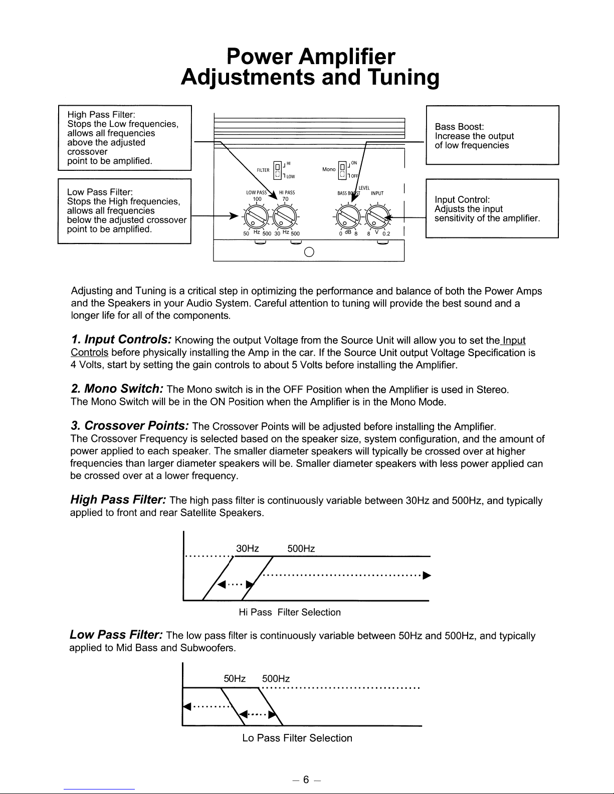
High Pass Filter:
Stops the Low frequencies,
allows all frequencies
above the adjusted
crossover
point to be amplified.
~'"
Low Pass Filter:
Stops the High frequencies,
allows all frequencies
below the adjusted crossover
point to be amplified.
Adjusting and Tuning is a critical stepinoptimizing the performance and balanceofboth the Power Amps
in
and the Speakers
longer life for all
1.
Input
Controls before physically installing the Amp
4 Volts, start by setting the gain controls to about 5 Volts before installing the Amplifier.
Controls: Knowing the output Voltage from the Source Unit will allow you to set the Input
your Audio System. Careful attention to tuning will provide the best sound and a
of
the components.
FILTER
rl
LJ
llOW
LOW
PASSHIPASS
100 70
....
-~-~-
50Hz50030Hz
'-'
500
'-'
in
the car. If the Source Unit output Voltage Specification is
Mono
~
LJ
lOFF
~}
LEVEL
BASS
B
INPUT
~"'"
-,
0
,-,
0 , I
o
dB
8 8' V
0
I
I
0.2
I
'-'
I
Bass Boost:
Increase the output
of low frequencies
Input Control:
Adjusts the input
sensitivityofthe amplifier.
2.
Mono Switch: The Mono switch is
in
The Mono Switch will be
3.
Crossover
The Crossover Frequency
power applied to each speaker. The smaller diameter speakers will typically be crossed over at higher
frequencies than larger diameter speakers will
be crossed over at a lower frequency.
Points:
the ON Position when the Amplifier isinthe Mono Mode.
The Crossover Points will be adjusted before installing the Amplifier.
is
selected based on the speaker size, system configuration, and the amount
High Pass Filter: The high pass filter
applied to front and rear Satellite Speakers.
Low
Pass Filter: The low pass filter
applied to Mid Bass and Subwoofers.
~------~---~
50Hz 500Hz
in
the OFF Position when the Amplifier is used in Stereo.
be.
Smaller diameter speakers with less power applied can
is
continuously variable between 30Hz and 500Hz, and typically
30Hz 500Hz
......................................
Hi Pass Filter Selection
is
continuously variable between 50Hz and 500Hz, and typically
~
••••...•..............................
of
Lo Pass Filter Selection
-6-
4.
System
channels are functional, you may load your choice
good level, or lots
adjusted with the tone controls set to flat position and the balance and fader
source unit. If a Sub Woofer level control is used with this system set it to about 1/2 or 50%
Turn the source unit up all
each input on the amplifier. Once you can play the source unit at full power you can adjust each channel at
the amplifier until the clip light is on during the peaks. This adjustment is subjective and can be done by
observing the peak indicators on the amp as well as listening for what you determine
audible clipping from the speakers. The Bass Boost control can now be adjusted. The Bass Boost will
increase the electrical low frequency output
bass speaker or speakers can handle the power without damage.
Also check to make sure that the Bass or Sub woofer output
Adjust the Front
position. Understanding the type
setup. If the end user will play back low dynamic range classical material, you may wish to set the gains
higher. If the end user plays back extremely high dynamic range high energy material, set the system up
so that there
longer life for the Speakers
Power
is
a reasonable amountofprotection against abuse to the components. This will guarantee a
Up: Initial Tuning: Once the system
of
Media to set the system levels with. Media with a
of
energy including drums, bass, voice etc is advisable. The gain controls should be
of
the way. If the amp channels are clipping, back down the gain controls at
of
the system as much as 8 dB at 45Hz. Make sure that the
...
Rear balance so the imageisoptimum with the Front / Rear faderinthe center
of
Media that willbeplayed back on this systemisimportant for this
in
the system.
is
turned on and itisverified that all
in
the center positions on the
of
is
a safe level
of
the Amplifier is not greatly overdriven.
its rotation.
of
This initial tuning may
Media should nowbeplayed back to critique the sound performance and determine if further tuning is
nessary.
5.
Bass Boost Control: The Bass boost control will boost the Low Frequency at 45Hz.
The boost control has a Range from
adjusting this control to prevent overdriving the Woofer or Overdriving the Amplifier
The Clipping indicator
6.
Detailed Tuning: For the best overall results it
Audio System should
necessary to deal with Acoustic problems that so frequently occur
preferences and requirements
require the use
If you are connecting your Power Amplifiers to an Eclipse Source Unit with the E-iSERV feature, the
real-time Analyzer will
(See details
ofanAcoustic Realtime Analyzer.
in
your Eclipse Head unit Owner's Manual)
be
done by ear andinmany casesisgood enough. However different types
OdBofboost to +8dBofBoost. Caution should be taken when
or
both.
is
a good guide to use when setting the boost level.
is
highly recommended that fine tuningofyour
be
done by an Authorized Eclipse Dealer. After initial setup has been done it may be
in
Mobile Audio Systems, or particular
of
the end user. The detailed tuning procedures required at this point often
be
built into the Source Unit.
of
-7-
 Loading...