

Page 1
ECLIPSE®
EA2000/EA4000 Ownerls Manual
2 / 4
Channel
,,,.~.
LOW'OSI
00
~
I'tZSlO:IO
-
o
Integrated
0 0
Series
EA2000
L'ECLIPSE
0.
UTIO
IIIQf1 0
lIIl
'"
UU
PIIU'"
6
~
0
0
100>
SPEAKER
001
19°0-01
IllID6ED
u _
"'ASI
!OO
-0
~.
"""'"
0
~~,
00
01'
",
-
'USE
•.
_
LJ-
Power
TT.AEIlOIE
GICI
10001
0
o
Amplifier
EA4000
L'ECLIPSE
o
Thank you for purchasing the EA2000(2 channel) I EA4000(4 Channel) Intergrated Series Power Amplifier.
Please read this Owner's Manual before use. Be sure to read the Safety information section.
Keep this Owner's Manual together with the Warranty information
uuu
in
a safe place for later reference.
Page 2
Table
For
your
safetyinusing the EA Series Amplifiers 3
About Your Amplifier 4
Installation Requirements 5
Power Amplifier Adjustments and Tuning 6
Names and FunctionsofTerminals 9
Basic System Connection 10
of
contents
AVN Connection Examples
Head Unit Connection Examples 12
Troubleshooting 13
Specifications 16
11
-2-
Page 3
For your safety
Warnings and caution signs, illustrated below, are posted throughout this manual as well asonthe
EA2000/EA4000. They show safe and correct ways to handle the product to prevent personal
injury to you and others and to avoid damage to property.
Before reading through the manual, take time to read through and learn the important information listed
this section.
&Warning
&
Caution
in
using the
This sign indicates a situationinwhich incorrect handling through
disregardofa sign might resultindeath or serious personal injury.
This sign indicates a situationinwhich incorrect handling through
disregard of a sign might resultinpersonal injuryormay result solely
damage to property.
EA
Series Amplifier
&Warning
in
in
• This equipment requires 12V DC and should
only be installedina vehicle with a 12V negative
ground electrical system. Any other installation
may cause a fire or other severe damage to the
equipment and the vehicle.
• Do not disassembleoralter this equipment.
Accidents, fires or shocks may result.
• Do not let waterorforeign objects enter the
internal partsofthis equipment. Smoke, fires
shocks may result.
• Do not use when it is broken Accidents, fires or
shocks may result.
&
• When changing the installation location for this
equipment, please consult the dealer where
you bought it for safety reasons. Expertise is
necessary for removal and installation.
• Always replace fuses with fusesofidentical
capacity and characteristics. Never use a higher
rated fuse than the original. Using the wrong
typeoffuse may cause a fireorsevere
damage.
• If foreign objects or water enters the equipment,
smoke comes out,orthere is a strange odor,
stop using it immediately, and contact your
or
dealer. Accidents, fires,orshocks may result if
you continue to use itinthese conditions.
• Plastic bags and wrappings may cause
suffocation and death. Keep away from babies
and children. Never put bag over your head or
mouth.
Caution
• Be carefulofthe volume position when turning
the power source ON. Hearing damage may
result if very loud noise is emitted when the
power is turned ON.
• Keep volume to a reasonable level so that you
can hear sounds from outside the vehicle,
including warning sounds, voices, and sirens.
Failure to do so may cause an accident.
• Do not touch the heat dissipating partofthe
amplifier. Burns may result from the heat of this
part.
• Do not use this equipment except for in-vehicle
use. Shocks or injuries may result.
• Do not operate under abnormal conditions such
as when the sound is distortedorcuts out.
Fires may result.
• If placedindirect sunlight, metal parts may
heat, resultinginthe possibilityofburns.
•Ifthe equipment if dropped or the case is
broken, turn offthe power to the main unit and
contact your dealer.Ifusedinthis condition,
fires or shocks may result.
-3-
Page 4
About Your Amplifier
Your Eclipse PowerAmplifierwas Designed and Engineeredinthe USA for the best in
In
performance with the best components possible.
performance
of
yoursystem, we recommend a professional installation
Eclipse Dealer.
Power Supply: All Eclipse Amplifiers incorporate Powerful MOSFET Switching Power Supplies for
added reliability and powerful Music Reproduction.
orderto optimize the best
by
an authorized
Audio Amplifiers: The Eclipse Integrated Series use Symmetrical Analog Preamplifiers with Linear
Polar Power Stages for Musically Accurate Audio Reproduction.
Speaker Connectors: Flush Mounted Speaker Connectors allow Clean Installation with less risk
shorted wires. The speaker connectors will allow up to 10 Gauge wire interface.
of
Power Connectors: Eclipse Flush Mounted Power Connectors will accommodate up to 4 Gauge wire
for optimum power with very little Voltage Drop. As with the speaker connectors they provide less
opportunity for shorted conditions.
Fuse: Eclipse Power Amplifiers use ATC fuses. Do not replace blown fuses with fuses
rating. This Amplifier requires maximum two 30 Amp fuses. (One 30 Amp fuse for EA2000 and two 30
Amp fuses for EA4000)
of
a higher current
Eclipse Power On Indicator: When the Power Amplifier is powered on the Eclipse Brand Logo will
be Lighted.
Clipping Indicators: Each Amplifier has a clipping indicator LED located near the input gain control.
is
When the amplifier
optimum performance.
clipping this indicator will light. This indicator will help you to adjust the input gain for
Bi
-4-
Page 5
Installation Requirements
Before
The proper installation and system integrationofthis Power Amplifier will bring the optimum conditions for
high performance and a long trouble free life for your Mobile Audio System.
Please pay attention to the Installation hints listedinthis section for the best results.
1.
2.
You
Start: Congratulations on your purchase
of
this Eclipse Power Amplifier.
AmplifierLocation: Avoid Areas that may have excessive Moisture, and Heat such as the Engine
Compartment, or tire wells that are prone to flooding. Never mount Power Amplifiers under Carpet
creating a "Dead Air" condition, as overheating will result. Flat surfaces will prevent potential damage to
the Heat Sinks and Bottom Cover. Always check to make sure the Power Amplifier is not mounted on
topofthe Antenna Cable
Power Connections: B +Connections: The Power connectors will accept wire as large as 4 AWG.
For the best performance and lowest voltage drop theB+wire should be as large as possible, and
connected directly to the positive terminal of the Car's Battery. It is recommended that a fuse, a fusible
linkora breaker be installed nearthe battery to protect the Car's electrical systemincase a short
should occur between the battery and the Power Amplifier.
Ground Connections: The ground wire will carry the same current as the B+ wire so it should be at least
the same size. The ground wire does not have to run allofthe way to the Negative Battery terminal,
because the Car Chassisinmost cases is the same ground as the negative battery terminal. A good
ground screwedorbolted to the chassis where the paint has been carefully removed and conductive
grease applied will provide a lasting reliable connection. (In some cases the car's chassis may have
bad ground connections between the Battery and the Amplifier location.) If the positive wire is good
good between the Amps and the battery and a large volt drop occurs, it may be necessary to run a
good ground from the Amplifier(s) to the Negative Battery Terminal.
3.
Wiring: Cleanly dressed wiring will last longer and have less chances for noise coupling and possible
damage from materials transportedincompartments. Always install wiresina clean organized fashion
away from moving components, or body parts that may cut, bind, or wear through the insulation. Be
careful to route wires away from sheet metal screws that may cause intermittent shorts once the car
begins to move. Try to keep signal cables away from the power harness and the electrical harness for
the Car Electronics. Use Rubber Grommets where wiring breaks through the sheet metal asinthe
engine compartment firewallorrear trunk sheet metal partition.
-5-
Page 6
Power Amplifier
Adjustments and Tuning
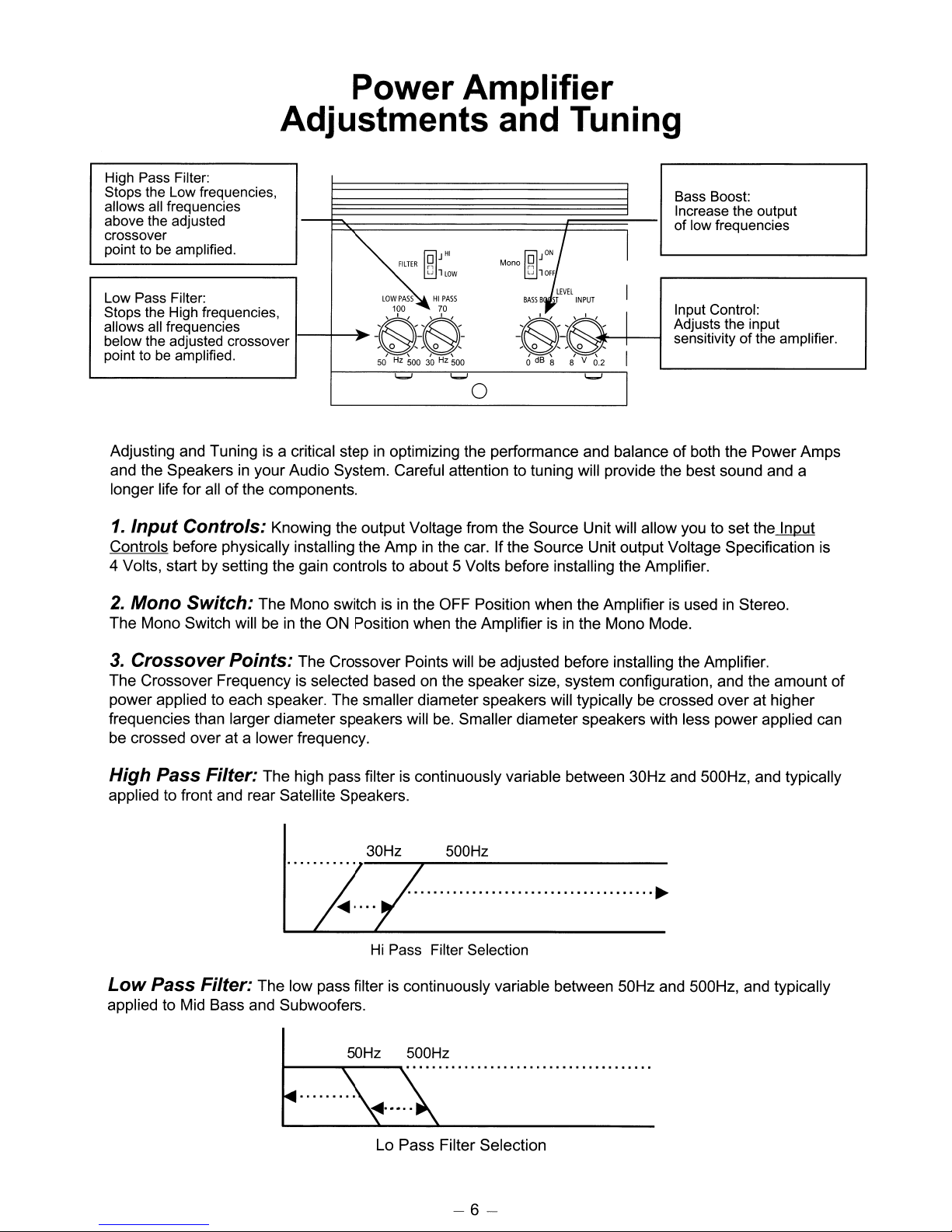
High Pass Filter:
Stops the Low frequencies,
allows all frequencies
above the adjusted
crossover
point to be amplified.
~'"
Low Pass Filter:
Stops the High frequencies,
allows all frequencies
below the adjusted crossover
point to be amplified.
Adjusting and Tuning is a critical stepinoptimizing the performance and balanceofboth the Power Amps
in
and the Speakers
longer life for all
1.
Input
Controls before physically installing the Amp
4 Volts, start by setting the gain controls to about 5 Volts before installing the Amplifier.
Controls: Knowing the output Voltage from the Source Unit will allow you to set the Input
your Audio System. Careful attention to tuning will provide the best sound and a
of
the components.
FILTER
rl
LJ
llOW
LOW
PASSHIPASS
100 70
....
-~-~-
50Hz50030Hz
'-'
500
'-'
in
the car. If the Source Unit output Voltage Specification is
Mono
~
LJ
lOFF
~}
LEVEL
BASS
B
INPUT
~"'"
-,
0
,-,
0 , I
o
dB
8 8' V
0
I
I
0.2
I
'-'
I
Bass Boost:
Increase the output
of low frequencies
Input Control:
Adjusts the input
sensitivityofthe amplifier.
2.
Mono Switch: The Mono switch is
in
The Mono Switch will be
3.
Crossover
The Crossover Frequency
power applied to each speaker. The smaller diameter speakers will typically be crossed over at higher
frequencies than larger diameter speakers will
be crossed over at a lower frequency.
Points:
the ON Position when the Amplifier isinthe Mono Mode.
The Crossover Points will be adjusted before installing the Amplifier.
is
selected based on the speaker size, system configuration, and the amount
High Pass Filter: The high pass filter
applied to front and rear Satellite Speakers.
Low
Pass Filter: The low pass filter
applied to Mid Bass and Subwoofers.
~------~---~
50Hz 500Hz
in
the OFF Position when the Amplifier is used in Stereo.
be.
Smaller diameter speakers with less power applied can
is
continuously variable between 30Hz and 500Hz, and typically
30Hz 500Hz
......................................
Hi Pass Filter Selection
is
continuously variable between 50Hz and 500Hz, and typically
~
••••...•..............................
of
Lo Pass Filter Selection
-6-
Page 7
4.
System
channels are functional, you may load your choice
good level, or lots
adjusted with the tone controls set to flat position and the balance and fader
source unit. If a Sub Woofer level control is used with this system set it to about 1/2 or 50%
Turn the source unit up all
each input on the amplifier. Once you can play the source unit at full power you can adjust each channel at
the amplifier until the clip light is on during the peaks. This adjustment is subjective and can be done by
observing the peak indicators on the amp as well as listening for what you determine
audible clipping from the speakers. The Bass Boost control can now be adjusted. The Bass Boost will
increase the electrical low frequency output
bass speaker or speakers can handle the power without damage.
Also check to make sure that the Bass or Sub woofer output
Adjust the Front
position. Understanding the type
setup. If the end user will play back low dynamic range classical material, you may wish to set the gains
higher. If the end user plays back extremely high dynamic range high energy material, set the system up
so that there
longer life for the Speakers
Power
is
a reasonable amountofprotection against abuse to the components. This will guarantee a
Up: Initial Tuning: Once the system
of
Media to set the system levels with. Media with a
of
energy including drums, bass, voice etc is advisable. The gain controls should be
of
the way. If the amp channels are clipping, back down the gain controls at
of
the system as much as 8 dB at 45Hz. Make sure that the
...
Rear balance so the imageisoptimum with the Front / Rear faderinthe center
of
Media that willbeplayed back on this systemisimportant for this
in
the system.
is
turned on and itisverified that all
in
the center positions on the
of
is
a safe level
of
the Amplifier is not greatly overdriven.
its rotation.
of
This initial tuning may
Media should nowbeplayed back to critique the sound performance and determine if further tuning is
nessary.
5.
Bass Boost Control: The Bass boost control will boost the Low Frequency at 45Hz.
The boost control has a Range from
adjusting this control to prevent overdriving the Woofer or Overdriving the Amplifier
The Clipping indicator
6.
Detailed Tuning: For the best overall results it
Audio System should
necessary to deal with Acoustic problems that so frequently occur
preferences and requirements
require the use
If you are connecting your Power Amplifiers to an Eclipse Source Unit with the E-iSERV feature, the
real-time Analyzer will
(See details
ofanAcoustic Realtime Analyzer.
in
your Eclipse Head unit Owner's Manual)
be
done by ear andinmany casesisgood enough. However different types
OdBofboost to +8dBofBoost. Caution should be taken when
or
both.
is
a good guide to use when setting the boost level.
is
highly recommended that fine tuningofyour
be
done by an Authorized Eclipse Dealer. After initial setup has been done it may be
in
Mobile Audio Systems, or particular
of
the end user. The detailed tuning procedures required at this point often
be
built into the Source Unit.
of
-7-
Page 8

Quick
1.
Set Crossover
Configuration.
2.
Turn the Gain
3.
Turn the Bass
4.
Test the speaker wirestoguarantee there arenoshortstothe Car
the Amplifier.
5.
Connect the B+
6.
Connect the Speaker Wirestothe Amplifier.
7.
Connect the RCA Cablestothe RCA
8.
Turn the Source Unit on and Turn the Volume down.
9.
Load the Source
10. Turn the Volume
Adjust
11.
Amplifier
Adjust
12.
correct.
13. Depending on the sound, you may
If
14.
1S.Listen
16.1f
17.RTA the System and
18. Make final
the Gain
the
Bass
Boostisnecessary
to
Equalizationisapplied a Real Time Analyzer
Points
Controls
Boost
are
justonduring
Input
several different
Adjustments
before installing the
Control down, before
Power,
Unit
with
uptoMaximum at the Source Unit.
Controls
Gains on the
look
down
before installing the Amplifier.
Power Ground and Remote wirestothe Amplifier.
your
Set-Up Media.
on the
songs
for
with
Amplifier
peaks. Listen
Amplifierssothe Front-Rear and Left-Right Balance
wishtomake small adjustmentstothe
nowisthe timetomake adjustments.
and make final
Peaks and
the Bass
Set
Up Process
Amplifier
installing
inputs
on the Amplifier.
one channel at a timesothe Peak Indicators on the
for
acceptable levelsofdistortion.
Dips
which
Boost
Controlorwith
based on Speaker Size and System
the Amplifier.
adjustmentsbyear.
will
be useful now.
should
Body
before connecting
sounds
crossover
be Tuned Out.
the E-iSERV Processorboth.
points.
to
-8-
Page 9

Names and Functions
EA2000
of
Terminals
Power Connections
FUSE
~
Speaker Connections
I SPEAKER
Speaker
Speaker Out Left -
I +LEFT_
Out
L~
I I
I I
I I
Signal Input Connections
LINE
PREAHP
IN
+BATT.
3"
REMOTE
a
-Remote
OUT
+RIGHT_
~Speaker
+
BRIDGED
-
@
GND.
0
Connect
to
Chassis
turn
on
Directlyt
o battery with line
I
I
Out Right +
Speaker Out Right -
Ground
from source
fuse
PreAmp
Output
RIGHT
Connections
OUT
Hff-e-1r-----
Hff-&fr-----
lIHf
PREAMP
IN
OUT
r----If------
Left Signal Input
Right Signal Input
Left PreAmp Output
Right PreAmp Output
EA4000
Power Connections Signal
Speaker
Out
Front Left +
Front
Left-
Speaker
Out
Front Right
Front Right -
FUSE
30' 30'
00
Speaker Connections
+_.......;==::;s
--------'
+6ATT.
REMOTE
0 0
'---
fiiE4~;:::::==+
@
GND.
Connec
Remote
Directlyt
'-----1--+
""----+
t to
Chassis
Ground
turn on from source
o battery with line
Speaker
Speaker
Rear
Rear
Rear
Rear
Out
Left +
Left-
Out
Right +
Right -
Left Front Signal Input
Right Front
fuse
Input
-+----,-,=1
Signallnput-+----'
PreAmp
Output
Connections
LiNE
r
[N1
FRONT
REAR
Connections
LiNE
r
1N1
FRONT
REAR
LEFT
RIGHT
PREAMt
OUT
-.f1"?'\\,----+--Left
~~---+--Right
PREA1P
OUT
1-----'---
!----i---Right
Rear Signal Input
Rear Signal Input
Left PreAmp Output
PreAmp Output
-9-
Page 10

Basic System Connection
l
Mono
Speaker Connections 2 Channel
r==="J
, ,
+
JON
LJ
olOFF
~
EA2000
JON
Mono R
LJ
1
OFF
~
Speaker Connections Bridged
SPEAKER
+LEFT_ +"IGHT_
+
OUT
BRIDGED
r==="J
, .
+
-I
Front / Rear
l
Mono
JON
LJ
olOFF
~
Speaker Connections 4 Channel
EA4000
Speaker Connections 3 Channel
Front / Rear
JON
Mono
Speaker Connections Bridged
il
LJ
lOFF
~
Mono
+lEFT_
Front
l
LJ
o1
~
SPEAKER
FRONT
+RIGHT_
JON
OFF
OUT
Mono
Rear
~JON
~
LJ
1
OFF
+LEFI_
FRONT
+RIGHT_
- 10 -
SPEAKER
OUT
Page 11

AVN Connection Examples
AVN Connections Internal Power + Subwoofers
EA2000
.
':
Non-Fader Out
II.
_
.II
I
Rear Left Speaker
Rear Right Speaker
AVN Connections EA4000 exampleof3 channel install
.
.
E8.
1::::::=======I==F======:l
Front Left Speaker
Front Right Speaker
EA4000
•
~
:
~
, ,
Rear
•
Left Channel
Right Channel
Front
Sub
Front Out
Non-Fader
AVN connection using the EA2000 and EA4000
Non Fader Out
.
.
Out
EA2000 Bridged
EA4000
•
•
Front Out
Rear
Out
l...----r---~'11
Front
Front
Rear
-
11
-
Page 12

Head Unit Connection Examples
AVN
Head
Unit
Connections
Connections
Non-Fader
_____
Rear
Right
EA4000
Out
Speaker
exampleof3
Internal
~~~
F_ro_nt_Le_ft
Front
Right
Rear
Left
._t:;'l
_Sp_ea_ke_r
Speaker
Speaker
Power+Subwoofers
Rear
channel
install
Left
--'~
Front
Channel
Head
'-------1Lo
Front
Non-Fader
Unit
connection
EA2000 Bridged
Non
•
Out
Out
Fader
•
Out
rD
using
EA4000
the
EA2000
and
OOlooot
Sub
Front
EA4000
Front
Front Out
Rear Out
•
EMOOO
•
=
~-
-
OOlo;or
Rear
Page 13

Troubleshooting
If
a problem occurs after
forsolutions.
contact Eclipse Technical Supporl
Problem Possible Cause Possible Solution
1.
Amp won't power on No fuse installedinthe amplifier or fuse Install fuse.
If
aftercarefully following these instructions you stillhave a problem, please
is
your
blown
system is installed, please referto this troubleshooting section
at
1-800-233-2216
Battery B+ not Powered on
is
Ground Cable
Remote line in is not powering on
2.
Amp Blows Fuses Power CablesinReverse Polarity
Wrong size fuse installed
3.
Ampison but no RCA cables not connected Make sure RCA cables are connected on
sound from one
more channels
or
Defective RCA Cable
not connected
in
amplifier
Check for
Make sure B+ Cableisconnected to the
Battery.
Check for 12Vbetween B+
connector
Make sure ground Cable is connected to
both amp and vehicle Ground.
Aftertuming
Between amp
Make sure the remote wireisconnected to
the correct remote output from the source
unit.check connections and power at
source unit.
Make sure B+
connected to the correct terminals:
Connect correctly.
Make sure fuse size is correct:
Check spec Sheet ( backofthis
correct size.
both ends:
Make connections.
Test RCA Cable for Signal: Replace
necessary.
12VatAmp
and
Amp
Ground Connector:
the
Sourre
pwr
gnd
and
Pwr
B+ Terminal:
amp
on.
measure for
and remote terminal
GND cables are
book)
voltage
for
if
Speaker wires not connected
Speaker wires connected to wrong
terminals
Input Gain Controls turned down Make sure gains are adjusted to source
4.
Amplifier goes into one or more speakers is shorted Make sure there are no speaker shorts
protect mode with the amplifierturned off:
- 13 -
Make sure speaker wires are connected
on both ends:
Make connections.
Make sure speaker wires are connected
to the correct terminals.
unit.
Disconnect speaker from amp and test for
a short across the Speaker.
Test for a short between the speaker and
of
chassis or body
With the speakers connected
turned off:
Test for a short between the amplifier
output and the chassis or body
the car.
and
of
amp
the car.
Page 14

5.
Amp
6.
Distorted
Problem Possible Cause
has
engine
noise
Speaker ground is shorted to car body
of
RCA connector is
Output
Outer barrel
shorting to the Amplifier chassis
Amplifier gain is too high
Possible Solution
Test for negative speakerspeaker short:
Make sure negative speaker lead is not
or
shorted to vehicle chassis
With amp off. disconnect RCA Cables
body.
And
test for the impedance between the Barrel
of
the RCA
If no negative speaker lead short, the
impedance
Call Eclipse Technical support.
Turn amplifier gain down so clipping
LED turns on during peaks, or level is just
below audible distortion.
and
the amp powerground.
is
nearly shorted (low resistance).
7.
Unit Turns on and off
8.
Poor
Bass
Output
Too much input signal
Damaged Speaker
Source Unit output is distorted
Speaker is shorted
or
Poor connection to Power wires
Battery connection
Gain Control for Subwoofer is too low
Crossover is set up incorrectly
Subwoofer is wired out
of
phase
Poor
Source unit output level is more then 8
Volts RMS: Reduce gain at Source Unit.
Check Speaker with alternative Source:
Replace Speaker.
Test Source Unit with alternate system
like a Displayorfunction verification unit.
Replace Source Unit.
Test for shorted speaker: Remove short
or
from speaker,
Test connections
replace shorted Speaker.
at
B+ cable
and
Power
Ground: Repair Power Cable connections.
Check Source Unit settings and Input
Gain Control: Adjust gain control on
or
Source Unit
at amplifier input.
Check crossover frequency settings:
Adjust Crossover.
Check subwoofer wiring
Correct wiringofsubwoofer to be in phase.
and
phase:
Acoustical misalignment
Tone Controls on Source Set Incorrectly
of
subwoofer
-
14-
Check to be sure the
box
is not to small
for the Subwooferoperating parameters
Correct box size.
Check to make sure the tone controls are
set to a flat position andnottocutposition:
Set tone controls to flat or by pass position.
Page 15

Problem Possible Cause
9.
Speaker
pops
when
unitisturnedonor off
Source
amplifier
unit
maybesending
pop
noise
Possible Solution
to
Disconnect RCA inputs then turn source
unit on
If
and
pop
noiseisgone
off:
try
a
different
Source
Unit.
10.
11.
12.
Bass
Boost
Amp
runs hot
Amp
won't shut off
Distorted
Possible
DC
Input
controlisturned
Inadequate
Load
ground
loop
offsetatamplifier
gain
set
too
highorremote
all
ventilation
impedanceistoo
the
noise
output
way
low
Remoteonwireisstaying
sub
up
highorat
level
12V
Check to make sure grounds are correct
so No ground loops can exist:
Ifapoor
Measure the amountofDC
across the speakerconnectors
output
Ifthe
output
turn
Check gain settings:
ground
of
DC
is
on
sound. Change the amplifier.
exists
correct
the Amplifier:
the
voltage
offset voltageatthe amplifier
greater then 70mV it will cause a
grounding.
at
the
Readjust gain settings with remote sub
control at center position.
Make sure unit has proper ventilation:
Check load impedance against the
specifications:
Connect the proper load impedance.
Measure voltage between Remote on
terminal and the
power
ground terminal:
Ifthe voltageishigh disconnect the
Source Unit
and
see ifthe amp shuts
off.
If it does try a different source unit.
- 15 -
Page 16

Specifications
Power Output: RMS Power
-------------EA2000-------------
4 n @
n @
4
n @
4
-------------EA4000-------------
4 n @
n @
4
n @
4
20Hzto20KHz
20Hzto20KHz
20Hzto20KHz
20Hzto20KHz
20Hzto20KHz
20Hzto20KHz
at
14.4 Volt Power
Stereo
Bridged
Stereo ( CEA 2006 )
Stereo
Bridged
Stereo ( CEA 2006 )
Max Power Output: Peak Music Power
-------------EA2000-------------
4n Stereo @ 1
4n Bridged @ 1
-------------EA4000-------------
4n Stereo @ 1
4n Bridged @ 1
KHz
KHz
KHz
KHz
Input Sensitivity
Supplv@
<1%THO
<1%THO
at
14.4 Volt Power Supplv
< .1%
THO
60WX2
175W X 1
75WX4
150W
90WX2
225W X 1
100WX4
175WX2
200mV
X2
...
8V
High Pass Frequency Selection
low
Pass Frequency Selection Variable
Bass Boost
Subsonic Filter
Signal to Noise ( CEA 2006 )
Frequency Response
Channel Separation
Damping Factor
Idle
Quiescent Current (
Current)
Maximum Current
Amp Protect Temperature
(Heat
Variable
Sink)
20Hz - 20KHz
18dB
EIA /
30Hz...
50Hz...
0-
8dB
@45
/ octave @20Hz
>
+0,
<
IHF
EA2000 30Amps
EA4000 60Amps
>
::1Amp
500
500
100
-.5
70
50
Hz
Hz
Hz
dB
dB
dB
dB
90C
-
16
-
Page 17

- 17 -
Page 18

- 18 -
Page 19

- 19 -
Page 20

CUSTOMER NOTICE
Please retain this booklet and write in the serial number
of
your new Amplifier for identification.
The serial number is labeled
Serial
No.
or
stamped on the chassis.
FUJITSU
Contact:
19600
800·233·2216
TEN
FUJITSU
So.
Vermont
LIMITED
TEN
CORP.OF
Avenue,
Torrance,CA90502
AMERICA
www.eclipse-web.com
"ECLIPSE"isa registered trademark of
FUJITSU TEN LIMITED in 48 countries
including the U.S. and Japan.
090003-285007000503(CN,K)
Page 21

LECLIPSE
IMPORTANT
SHOULD
YOU HAVE ANY QUESTIONS,
call:
OJ
FUJITSU
TEN
1-800-233-2216
FUJITSU
19600S.Vermont Avenue, Torrance, CA 90502
TEN
CORP.OFAMERICA
PLACE
FIRST-CLASS
STAMP
HERE
FUJITSU
Warranty Registration
19600
Torrance, CA 90502
TEN
S.
Vermont Avenue
CORP.
OF
AMERICA
Page 22

Eclipse(adivisionofFujitsu
workmanship
purchaser
in
the
Foraperiodofone
under
authorized
atnochargetothe
vice
departmentorretailerinorder
Eclipse
THERE
foraperiodofone
(this
United
warrantyisnot
StatesorCanada.
year
this
warranty,
Eclipse
repairorreplace
retailer,
original
shall
not
refund,
ARENOWARRANTIES,
ECLIPSE
Ten
Corp.ofAmerica)
year
from
transferable),
from
the
dateoforiginal
transportation
purchaser
norberesponsible
withalike
during
for
WHICH
prepaid
the
EXTEND
the
ownertoreceive
and
the
for,
original
only
mOdel
warranty
BEYOND
LIMITED
hereby
warrants
dateofpurchase.
when
this
purchase,inthe
any
any
unit
shall
period.
the
expenses
THE
Eclipse
productisoriginally
whichisdefectiveinmaterialorworkmanship,ifreturnedtoan
either
Service
benefitsofthis
paidorincurredbythe
DESCRIPTIONONTHE
EXCLUSIONS FROM ECLIPSE'S LIMITED WARRANTY
This
warranty
shall
not
1.
Eliminationofcar
tape
2.
3.
4.
5.
RfSfNrAflONS.
MADEBYANY
INCLUDJNG
ARE
SAME
HOW
ALS
AND
INCIDENTALORCON5EOUENTJAL.
SOME
SO
WARRANTY
CATES
VICE
lY
cartrrdges
Any
defectsInthe
ningorfluctuationinelectrical
and
necessary
or
serVicebynon-authorized
handling,orwhen
Cosmetic
Normal
wear.
Does
not
rHIS
WARRANTYISIN
AND
PERSONORFIRM
THE
WARRANTYO~MERCHANTA811,/1Y
HEREBY
MODIFIEDTOEXIST
DURATIONASTHE
LONGANIMPLIED
iN
THE
[VENT
'!'OUR
SOLE
REMEDY
UNDER
NO
CIRCuMSTANCES
STATES00NOT
THE
ABOVE
LIMITATIONOREXCLUSION
TO
OBTAIN
WARRANTY
PERIOD.
ThAT
THE
UNiT!SWiTH"';
vOU
WILLBERESPONSIBLE
'IVl
UNITORR£PtAC[f~AlliS
CON[.IIT/ONS
ARE
cover
static.
andoraudiO
opinionofEclipse.
maintenance,
the
damage
tear.
cover
removal
LIEU
UNLESS
SrATfD
WARRANTY
WARRANTY
THAT
YOUR
SHALL6EiHE
ALLOW
THE
SERVICE
YOUR
PROOfOfPURCHASE.
MET
fC:..,PSf
motor
nOise.orother
cables.
etc
power),
improper
Eclipse
model's
accessorres
battery
replacement
and
OF
ALL
HEREIN.
ARE
VOiD
ONLYASCONTAINEDIN/HIS
PERIOD
LASTS.soTHE
ECuPSE
PRODUCT
REPAIRORREPLACEMENT
SHALt
ECLIPSEB£LIABlE
MUSING
EXCLUSIONORLIMITATIONOfINCIDENTALORCONSEQUENTIAL
you
THE
WARRANTY
fOR
SHIPPING
SOLE
DISCR£1fON
WILL
COVER
Service
serral
number
(SUChasmagazinesorremotes)orproblemsordamage
reinstallationofproduct
OTHE,q
EXPRESSORIMPLifO
ALl
SUCH
ALL
IMPLifO
AND
STATED
ABOVE
ABovt
SHAL!
OUiOFTHE
MAY
NOT
APPIYTO
MUSTGOBACKTOAN
SUCHASA
PERIOD.
CHARGESroECLIPSE
WITHAi./KE
SHiPPING
electrrcallnterference,
causedbyabuse.
liquid
Installation
Department,
has
and
any
WARRANfJfS
WARRANflESINCONNECTION
THF
WARRANTYOFFITNESS
LiMITED
SOME
i/MJrATlO,V
PROVE
;OR
USE
OF.ORiNABIl
YOU
AUTHORllEO
BILLOfSAlEORRECEIPTEO
MUST
Sf
MODEL
OiARGtS
misuse,
damageordamage
(suchasinsufficient
been
removed,
perrodlc
maintenance
WARRANTiES.
STATEMENTSORREPRESENWIONS
WARRANTy
STATESDONOT
MAY
NO!
DEFECTIVEiNWORKMANSHIPORMATfRI
ANY
APPLYTOYOU
REMEDYASSTATEDINTHIS
LOSS
OR
DAMAGE.
In'
TO
USE.
iCt/PSt
PRESENTED
TO
ECUPSE
WITrlOUT
TO
qflURN
accident
useofcomponent
STATEMENrsORREp·
FORAPARTICULAR
AND
ALLOW
THIS
RETAiLER
INVOICE
OBTAiN
WILL
RfPAIR
CHARGE
THE
UNITTOYOU
correctIOnofproblems
causedbyattempted
alteredOrdefaced
WITH
SHALLBEOF
LlMITMIONS
WARRANT~
WHETHER
ECLiPSE
WITHIN
WARRANTY
THE
IF
ALL
WARRANTY
your
Eclipse
producttobe
This
warranty
purchased
unlikely
event
that
repairorreplace,atits
work
mustbeperformedbyan
warranty
(including
grounding),
THIS
DIRECT.
PRODUCT
DAMAGES
THATINOI·
DEFEe
WARRA~·
SAL
USt
S£R
parts
THi
ON
THE
any
Improper
not
[
damages
theftornegligent
approvedbyEclipse
causedbythe
free
applies
from
onlytothe
fromanauthorized
your
Eclipse
unit
sole
discretion,
owner
under
this
FACE
HEREOF
resulting
from
the
causedbyactsofGod
use.
Installationofother
Failuretoperform
Damage
applicationoruseofdefective
EA2000
I""'"
"'""""'"
defectsinmaterial
original
Eclipse
should
fail,
Eclipse
the
Eclipse
authorized
Eclipse
warranty.
antenna
system.
suchasflood,
components,
causedIntransitorin
"'" "'"
""""
and
consumer-
retailer
shall,
product
ser-
CO's,
MO's.
light-
reasonable
mOdification
media
Please detach here before mailing.
LECLIPSE
Please printortype the information
listed below
RetaiIe
r's
Name:
Street:
City
DateofPu
Car
Owne
Street:
City
Pho
Ins
Owner's
Comments:
rchase
Make:
r's
Name:
neNumber:
taIIe
r:
E-mail
and
mail.
L--'---'-I_-'---'-......J._-"---"----J_..L..-L_L--'---'-_'---'---'-_-"---'----'_.L--'----''---'--'
: .
Mr.
first
Name
LI
---,1_-'--'---..JL-..L..-1.._'---'---'-_-'---'---'
I I I
I
I I I
I
1
I
I-
Month
I I
I
I I I I
Mrs.
Day
I-I
I
Ms.
I
Yea:
I
1 I
1 1
1 I -
LI
--,-1_
......
1--'-_'---'--'----'----''---"---'----'----''---'---'--'--'
Address
1'----'--'------'_-'---'----'---'
Model
Serial
Number:
Number:
090000-01270700
0503MT(N)
1111I1111111111111111111I1111I1111I1111I
EA2000
_
We
willbesending
Which
methodismost
youaquestionnairetoassistusin
convenient?
E-mail
developing
.
Mail
new
products
for
you
Thank
You.
 Loading...