

Page 1

ECLIPSE
E:A,
S~&~wit4.&d#uu
XA,
and
Amplificateurs
Manuel
L'e~
4~ti~
E:A,
XA,
.wee
&d#uu
l.d
ZA
MUal
.,14
S6Hie4
&~
e-
&d#uu
ZA
Owner's
du
Serie
del
Series
Amplifiers
Manual
E:A,
XA
proprietaire
de
Amplificadores
Usuario
et
ZA
Page 2

Page 3
For
your
safety
in
using
the
EA,
XA
and
ZA
Series
Amplifier
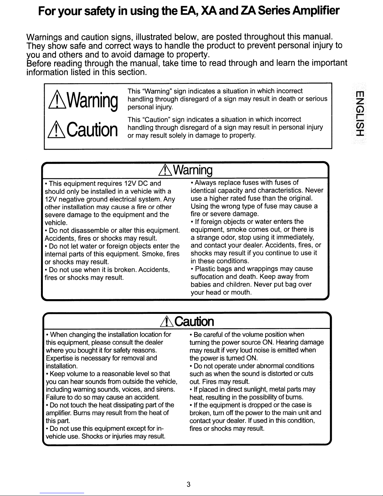
Warnings and caution signs, illustrated below, are posted throughout this manual.
They show safe and correct ways to handle the product to prevent personal injury to
you and others and to avoid damage to property.
Before reading through the manual, take time to read through and learn the important
in
information listed
&Warning
~Caution
this section.
This "Warning" sign indicates a situationinwhich incorrect
handling through disregard
personal injury.
This "Caution" sign indicates a situation in which incorrect
handling through disregard
or may result solely in damage to property.
of
a sign may result in death or serious
of
a sign may result in personal injury
&Warning
may
of
or
cause
• This equipment requires 12V DC and
should only be installed in a vehicle with a
12V negative ground electrical system. Any
may
other installation
severe damage to the equipment and the
vehicle.
• Do not disassemble
Accidents, fires
• Do not let water
may
of
result.
internal parts
or shocks
• Do not use when it is broken. Accidents,
fires or shocks may result.
cause a fire or other
or
alter this equipment.
or
shocks may result.
or
foreign objects enter the
this equipment. Smoke, fires
• Always replace fuses with fuses
identical capacity and characteristics. Never
use a higher rated fuse than the original.
of
Using the wrong type
or
fire
•
equipment, smoke comes out, or there is
a strange odor, stop using it immediately,
and contact your dealer. Accidents, fires,
shocks
in these conditions.
• Plastic bags and wrappings
suffocation and death. Keep away from
babies and children. Never put bag over
your
severe damage.
If
foreign objects or water enters the
may
resultifyou continue to use it
headormouth.
fuse may cause a
• When changing the installation location for
this equipment, please consult the dealer
where you bought it for safety reasons.
is
Expertise
installation.
• Keep volume to a reasonable level so that
you can hear sounds from outside the vehicle,
including warning sounds, voices, and sirens.
Failure to do so may cause
• Do not touch the heat dissipating part
amplifier. Bums may result from the heat
this part.
• Do not use this equipment except for in-
vehicle use. Shocks or injuries may result.
necessary for removal and
an
accident.
LhCaution
• Be careful
turning the power source ON. Hearing damage
may result
the power is turned ON.
Do
not operate under abnormal conditions
•
such as when the soundisdistorted or cuts
out. Fires may result.
• If placed
heat, resulting
of
the
of
• Ifthe equipment is dropped orthe case
broken, turn off the power to the main unit and
contact your dealer. If used in this condition,
fires or shocks may result.
3
of
the volume position when
if
very loud noiseisemitted when
in
direct sunlight, metal parts may
in
the possibilityofburns.
is
Page 4
About Your Amplifier
Thank
Your Eclipse Power Amplifier was Designed and Engineered
performance and Manufactured with the best components possible.
the best performance
authorized Eclipse Dealer. If you decidetodo your own installation itiscritical that
you read this Manual to help understand the steps necessary to get the maximum
J:
performance from your new product. These Power Amplifiers are designed with the
~
appearance similartoa Beautiful set of polished wheels and should
<:5
respect to protect the Beauty and Integrity ofthe Product.
You
for Your Purchaseofthis Eclipse Mobile Power Amplifier.
in
your system we recommend a professional installation
in
the USA for the best
In
order to realize
be
treated with
Z
W
Planning the Installation
Before installing this Amplifier
and tune the controls for proper matching between the Source Unit, the Amplifier and
the Speaker System.
1.
Amplifier
enough space for mounting hardware to be applied to the Four notches
in
the baseofthe product. Find a location for the Amplifier that will allow
adequate ventilation for cooling. Even though this product
is a power product and will require some air flow for the best cooling. Make
sure the installation location is
contamination. Never install this product
2.
Wiring: Make sure the wiring to and from the Amplifier is protected from possible
short circuit by sharp metal components or metal parts that can damage wiring
when the car
walls or metal sections of the car should have grommets installed
protection against short circuits due
Location:
is
reassembled after the installation. Wiring passing through fire
The Amplifier should be mounted to a flat surface with
be
sure you understand the features and how to adjust
is
very efficient it
in
a dry area away from possible water or liquid
in
the engine compartment.
on
them for
to
vibration and age.
by
in
an
Installing the Amplifier
1.
Before You
safe installation by eliminating the risk of having shorted power wiring while working
on the car.
Note:
You
start:
may refertoCrossover Frequency Selection before Mounting
Disconnect the negative battery terminal. This will ensure a
the
Amplifiers.
4
Page 5

Installing the Amplifier
2.
Mounting the Amplifier:After a suitable location has been selected and the
wires routed, the Amplifier can be attached to the Vehicle. Start out by removing
of
the Polished Aluminum Trim Covers from the top
Hardware and the Wire Connections can be made. Set these aside
so they can be reinstalled after the Amplifier installation
location space is limited the Polished end covers may all
overall size
Lt
Caution
of
the Product.
Never use a power tool to drive the mounting hardware while
mounting this product. The Drill Chuck will damage the Heat Sink and Possibly
the Connectors! The wiring can be connected to the Amplifier before or after it is
attached to the Vehicle. Dressing the wiring is easier to do after all connections are
made.
3.
Power Connections: Pay attention to the polarity of the wires as
them to this product. We recommend at least 8 AWG Wire for connection between
anyone
of
the Amplifiers Battery Connectors and the Vehicle. The Power connectors
will accept wire as large as 4 AWG. For the best performance and lowest voltage
drop the
wire should
be
as large as possible. It is also recommended that a Fuse
B+
be placed within 18 inches of the positive Battery Terminal to protect the Car from
possible short circuits between the Amplifier locations and the Battery. The ground
B+
wire will carry the same current as the
The ground wire does not have to run all
in
because the Car Chassis
most cases is the same ground as the negative battery
wire so it should
of
the way to the Negative Battery terminal,
terminal. A good ground screwed or bolted to the chassis where the paint has been
carefully removed and conductive grease applied will provide a lasting reliable
connection.
the Amplifier so the Mounting
in
a safe location
is
complete. Ifthe Amplifier
be
removed reducing the
You
connect
be
at least the same size.
m
z
G)
r-
-
(J)
:c
+BATT.
REMOTE
GND
LtCaution
000
---
----
-------
._,,"
..
-
_._---_
..
__
---
-
000
._-----------
---
_.~_.-
Be Sure
--
._-----~
---------
1---
--------
---'_.
- -
ATTENTION
To
Check Polarity
Before Connecting.
(Connections may Vary)
o
Note:
Alternator Stand and the Vehicle Chassis to make sure that it
current
Strip about 5/8 inch (16mm)
connected to the Amplifier.
Optional: For that clean install you may wish to "tin" the bare ends
soldering iron before connecting to the amplifier.
With the Allen (Hex Key) wrenches provided back the hardware out enough to insert the wires
into the Power and Speaker Connectors and connect the wiring to the Amplifier being careful
to not overtighten and possibly strip out the Mounting Screws. Connect the RCA Connectors to
the Amplifier.
You
should check the Ground Wire between the Battery and the Vehicle Chassis and the
is
large enough to carry heavy
in
the case that multiple Amplifiers are installed.
of
insulation from the Power and Speaker wires that need to be
of
the wiring with a
5
Page 6
Adjusting the Amplifier
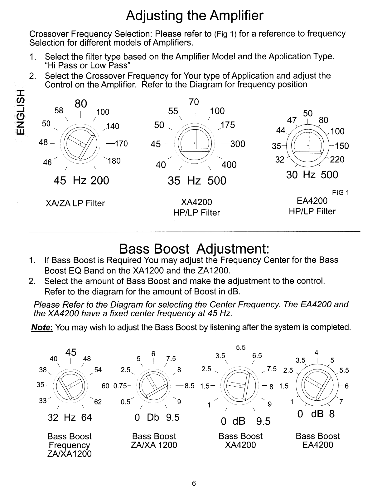
Crossover Frequency Selection: Please refer to (Fig1)for a reference to frequency
of
Selection for different models
1.
Select the filter type based on the Amplifier Model and the Application Type.
or
"Hi Pass
2.
Select the Crossover Frequency for Your typeofApplication and adjust the
Low Pass"
Control on the Amplifier. Refer to the Diagram for frequency position
J:
(J)
-
-I
C>
Z
W
58 I 100
50 "
48 - (
46 /
80
\ I
~~-~\
+\;
\ '
\ /
'https://manualmachine.com/
I \
/140
-170
"180
Amplifiers.
55 I
\ I
-'
/
,I
..
~
/
\
\,
"--_/
I \
50"
45
40
70
. !
100
'.
..
\.
;'
//
)75
-300
"
400
45 Hz 200
XAlZA LP Filter
35 Hz 500
XA4200
HP/LP Filter
FIG 1
EA4200
HP/LP Filter
Bass Boost Adjustment:
1.
If Bass Boost is Required
Boost EO Band on the XA1200 and the ZA1200.
2.
Select the amountofBass Boost and make the adjustment to the control.
Refer to the diagram for the amount
Please Refertothe Diagram for selecting the CenterFrequency. The EA4200 and
the XA4200 have
Note:
You
may wishtoadjust the Bass Boost by listening after the systemiscompleted.
a fixed center frequency at 45
45
40
\
38,~-~
48
I
I
/54
2.5,
You
may adjust the Frequency Center for the Bass
6
5
I
\
//--~,
I
7.5
/8
of
BoostindB.
Hz.
3.5 6.5
4
5
35-
(~\
/'
33
32
"'--'/
I
Hz
-60
/,
62 0.5
\
64
0.75-'~
Bass Boost
Frequency ZAlXA 1200
ZAlXA1200
-8.5
/'
"'---~/
I
0
Db
/-.......
\
9.5
9
dB
0
Bass Boost Bass Boost
XA4200
6
9.5
dB
0
8
Bass Boost
EA4200
6
Page 7

Amplifier
*Ifa subwoofer level control is used with this application at this time Turn the Control
full Clockwise (up all the way).
1.
Adjust the sensitivity controls full counterclockwise C8 V setting
Use a CD or DVD with High Energy Music and adjust the Gain to about 80%
of
the Source Units Maximum output. Make sure the Balance and Fader are
Center Positions. Make sure the Bass and Treble are boosted on the Source Unit.
2.
While playing Music increase the Amplifier Gain to a Point
in
distortion
Amp Gain Controls You May Fine Tune them individually with the entire system
running at a lower overall level. It is recommended that while tuning from this
point, Individual Amplifier Gains can be Attenuated to compensate for System
Balance.
the Music. Adjust eachofthe amplifiers individually. After setting the
Gain
Adjustment:
just
3 2.25 1.75
\ I /
4
"i/:?'~,
).
below audible
/"
1.35
in
m
Z
G)
r
-
(j)
:c
7
7.5 1.5
8 V 1.2
Gain Settings
EA4200
( \
7 - ( ) - 1.3
/
\~!J!"
7.5
/ \ 1.25
8 V
Gain Settings
XAand
1.2
ZA
7
Page 8

Troubleshooting
Ifa problem occurs after your system is installed, please refer to this troubleshooting
section for solutions.
J:
en
-
~
(!)
.:z
UJ
1.
2.
Problem Possible
Amp
wont
Amp
Blows Fuses Power Cables in Reverse Make sure B+ and PWR GND
power
on No fuse installed in the Install new fuse
amplifierorfuse is blown.
Ground Cable is not con- Check for 12V between B+
nected
Remote line
powering on measure for voltage Between
Polarity cables connected to the correct
Wrong size fuse installed in
amplifier
Cause
in
is not After turning Source on
Possible Solution
amp connector and Amp
Ground Connector: Make sure
ground Cableisconnected to
both amp and car Ground
amp power ground and remote
terminal. Make sure remote
wire is connected to the
Correct remote output from the
source unit. Check connections
and power at source unit
terminals: Connect correctly
Make sure fuse size
Check spec Sheet ( back
this book ) for correct size
is
correct:
of
3.
Amp
from one
is on but no sound RCA cables not connected Make sure RCA cables are
or
more channels
Defective
Speaker wires
Speaker wires connected to
wrong terminals
Input Gain Controls turned
down
RCA
Cable Test RCA Cable for Signal:
not
connected
connected on both ends: Make
connections
Replace if necessary
Make sure speaker wires are
connected on Both ends:
Make connections
Make sure speaker wires
are connected
terminals
Make sure gains are adjusted
to source unit:
To
the correct
8
Page 9

Troubleshooting
Problem Possible
4.
Amplifier goes into protect
mode
5.
Amp
has
engine noise
One
or more speakers
shorted
Input Gains turned
with
a low Impedance
Speaker ground
car body
is
Cause Possible Solution
are
uptofar,
Load
shorted
Make
speaker
With
disconnect
and
test
Speaker.
Test
speaker
the
car.
With
and
amp
short
output
of
the
Turn
Down.
to
Test
Make
leadisnot
chassisorbody.
sure
shorts:
the
amplifier
for a
for a
short
and
the
speakers
turned
between
And
car.
Input
for
negative
sure
there
the
Sensitivity
negative
shortedtocar
are
no
turned
speaker
short
chassisorbody
from
across
between
connected
off
Test
the
amplifier
chassisorbody
Control
speaker
speaker
off
amp
the
for a
short:
the
-
of
m
Z
G')
h
...
~
.:J:
6.
Distorted Output
Outer barrel of
torisshortingtothe Amplifier
chassis
Amplifier gain
Too
much
Damaged Speaker
Source Unit output
distorted
RCA
is
too
input signal
is
connec-
high
With
amp
off,
RCA
Cables
impedance
of
the
RCA
ground.Ifno
lead
short,
nearly
Call
Turn
so
audible
Source
then8Volts
at
Check
Source:
Test
system
function
Replace
shorted
Eclipse
amplifier
Audio
distortion.
unit
Source
Speaker
Replace
Source
likeaDisplay
verification
levelisjust below
Unit
Source
disconnect
And
test for
between
and
the
negative
the
impedance
(low
Technical
gain
output
RMS:
with
Speaker
Unit
with
Unit.
the
the
Barrel
amp
power
speaker
Is
resistance).
support.
down
levelismore
Reduce
alternative
unit.
gain
alternate
or
7.
Unit Pumps
on
and
off
Speaker
Poor connection
wires or Poor Battery
connection Power Cable connections.
is
shorted
Test
for shorted speaker:
Remove short
or replace shorted Speaker.
to
Power
9
Test
connections at
and
Power Ground: Repair
from
speaker,
B+
cable
Page 10

Troubleshooting
8.
Poor Bass Output
J:
(J)
-
-J
(!)
Z
W
Poor Bass Output
Problem Possible Cause
Gain Control for Subwoofer is
too low
Crossover is set up
incorrectly
Subwoofers are wired out
phase
Acoustical misalignment
subwoofer
Tone Controls on Source Set
Incorrectly
of
of
Possible Solution
Check Source Unit settings
and Input Gain Control:
Adjust gain control on Source
unitorat amplifier Input.
Check crossover freguency
settings: Adjust Crossover
Check subwoofer wiring
and phase: Correct wiring of
subwoofer to beinphase.
Check to be sure the
box is not to small for
the Subwoofer operating
parameters: Correct box size
Check to make sure the
tone controls are set
flat position and not to cut
position: Set tone controls to
flatorby pass position.
To
a
9.
Speaker pops when unit
turned on or off
10. Bass Boost Distorted
Source unit is sending pop
is
noise to amplifier
Possible ground loop noise
DC offset at amplifier output
Input gain set too high or
remote sub level control is
turned all the way up
Bass Boost Level Too High
Disconnect RCA inputs then
turn source unit
Ifpop noiseisgone try a
different Source Unit.
Check to make sure grounds
are correct so
can exist: If poor grounds
Correct the grounding.
Measure the amount of
voltage across The speaker
connectors at the output
the Amplifier: Ifthe
voltage at the amplifier output
Is
greaterthen 70mVitwill
cause a turn
the amplifier.
Check gain settings: readjust
gain settings with remote sub
control at center position
Readjust Bass Boost Level
and Amplifier Input Sensitivity
with Bass Boost Gain at the
Boosted Level.
on
and off:
No
ground loops
DC
offset
on
sound. Change
DC
of
10
Page 11

11.
Amp runs hot
T
rou
Inadequate ventilation
bleshooti
ng
Make sure unit has proper
ventilation:
Load impedance
12. Amp wont shut off
Note: If after carefully following these instructions you still have a problem, please
contact Eclipse Technical Support at 1-800-233-2216
Remote on wire
high or at 12V
is
too low
is
staying
Check load impedance
against the specifications:
Connect the proper load
impedance.
Measure voltage between
Remote on terminal and the
power ground terminal:
Ifthe voltage is high
disconnect the Source Unit
And see if the amp shuts off.
If it does try a different source
unit.
m
z
G)
r-
-
en
:c
11
Page 12

Specifications
EA4200 / XA4200
Power Output: RMS Power at 14.4 Volt Power Supply @
EA4200
40
@ 20 Hz to 20 KHz Stereo
I
~
...J
C)
20
40
@ 20 Hz to
@ 20 Hz to 20 KHz Bridged
20
KHz Stereo
XA4200
Z
W
40
@ 20 Hz to 20 KHz Stereo
20
40
Max Power Output: Peak Music Power at 14.4 Volt Power Supply
40
40
@ 20 Hz to 20 KHz Stereo
@ 20 Hz to 20 KHz Bridged
EA4200
Stereo @ 1 KHz
Bridged @ 1 KHz
XA4200
CEA
2006
60WX4
70WX4
140W X 2
100W X 4
200W X 4
400W X 2
100W X 4
170W X 2
40
Stereo @ 1 KHz
40
Bridged @ 1 KHz
Input Sensitivity
Low / High Pass Frequency Selection Variable (EA4200)
Low / High Pass Frequency Selection Variable (XA4200)
Bass Boost
Subsonic Filter
Signal to Noise
Frequency Response
Frequency Response
Channel Separation
Damping Factor
Quiescent Current
Maximum Current (EA4200)
(CEA 2006)
20Hz - 20KHz (EA4200)
20Hz - 20KHz (XA4200)
(CEA 2006) >80
( Idle Current) - 1.2Amp
30A Maximum Current (XA4200) 100A
250W X 4
600W X 2
1.2V- 8V
32
Hz-
500 Hz
40 Hz - 500 Hz
@45
8dB
18dB / octave @ 20Hz
>
80
+0, - 3
+0, - 0.5 dB
<
70
Hz
dB
dB
dB
Amp Protect Temperature
Dimensions (EA4200)
Dimensions (XA4200)
NOTE: Specifications are subject to change without notice.
( Heat
Sink)
90° C
7.5" (190mm) X 2.36" (60mm) X 10.1" (256mm)
12.2" (310mm) X 2.36" (60mm) X 10.1" (256mm)
12
Page 13

Specifications
XA1200 / ZA1200
Power Output: RMS Power at 14.4 Volt Power Supply @ CEA 2006
XA1200
40
@ 20 Hz to 20 KHz Mono
500W X 1
20
40
20
@ 20 Hz to 20 KHz Mono
@ 20 Hz to 20 KHz Mono
@ 20 Hz to 20 KHz Mono
ZA1200
1000W
1000W
Max Power Output: Peak Music Power at 14.4 Volt Power Supply
XA1200
40
Mono @ 1 KHz
ZA1200
40
Mono @ 1 KHz 1200W X 1
Input Sensitivity
Low Pass Frequency Selection Variable (Linkwitz Riley 18dB/Octave)
Bass Boost
Bass Boost Frequency Selection
o- 8dB Cont. Variable
32Hz - 64Hz Cont. Variable
40 Hz - 500 Hz
500W
X 1
X 1
X 1
700W X 1
1.2V-8V
m
z
G)'
.
r-~
-
CJ)
.,..,..'
....
Subsonic Filter
Signal to Noise
Frequency Response
Damping Factor
Damping Factor
Quiescent Current
Maximum Current (XA1200)
Maximum Current (ZA1200)
Amp Protect Temperature
Dimensions (XA1200)
Dimensions (ZA1200)
18dB
(CEA2006)
20Hz - 20KHz
(CEA 2006) (XA1200)
(CEA2006)
(Idle Current)
(Heat Sink) 90° C
(ZA1200)
10.2" (260mm) X 2.36" (60mm) X 10.1" (256mm)
12.2" (310mm) X 2.36" (60mm) X 10.1" (256mm)
I octave @ 20Hz
>
80
dB
+0,
-.5
dB
>90
>100
-1.2Amp
100A
160A
NOTE: Specifications are subject to change without notice.
13
Page 14

Controls
EA4200
I
en
-
.....J
.(9
Z
W
FILTER
LON, rHI OFF,
! • J
BASS
BOOST
5G{Q}
o dB 8
9G
8 V
--
2
MONO
rON
lOW,
i.
!
CROSSOVER
~[CJ
BASS
7G8
30
Hz 500 0 dB 8 30Hz500
-INPUT
12
FRONT--
10G
--
8 V 1.2
3
FILTER
BOOST
rHI
MONO
OfF,
CROSSOVER
g
-INPUT
REAR--
~
rON
l~==============
1-3 Hi / Lo Pass Filter Selection Switch
(Front and Rear)
2-4 Mono Selection (Front / Rear)
5-7 Bass Boost (Front / Rear)
6-8 Crossover adjustment (Front / Rear)
9-10 Input Level (Front / Rear)
r
LINEIN1
FRONT
1
REAR
XA4200
2 3 4 5 6 7 8 9
INPUT LEVEL
,I,
"8)'"
-.
. ; - !\ ) -
,
,,~-~,
I \ I \ I \ I \ I \ I \
8 V
1.2
+BAn
REMOTE
70-FILTER
,I/~
'(~"~"'\'
''''--.--:/"'
40 Hz
500
FRONT
-,
BASS BOOST INPUT LEVEL
,'I
~
HI
';sn~\'
LOW - " ) - \ .
,
~.,
a dB 8 8 V
,I,
'(e~'"
",=./'
1 LineIn(Front and Rear)
2-6 Input Level (Front and Rear)
3-7 Filter Frequency adjustment
4-8 High or Low Pass Filter switch
5-9 Bass Boost Adjustment
RIGHT
FRONT
GND
FUSE
-+-+-+-+
LEFT
70
- FILTER
\1/~
':~/~\'
.I
- " ) -
,\.~.,
1.2
40Hz500
REAR
RIGHT
REAR
LEFT
-,
~
HI
LOW - . -
BASS
BOOST
,II
'·sn---=-·"·'
,\,._/
a
dB
'
8
~:
l=~=:~
000
- - ..
o
·BRIDGED--
14
+ 0 -
.-
BRIDGED
- +
Page 15

Controls
XA1200
1~-_O_~
FRONT
€)
OJ OJ
~~
~
1 Line Input
2 Input Level
3 Bass Level Control
40A
FUSE
40A
8 V 1.2
INPUT
LEVEL
DoD
2 3
rffiffIl
~
LEVEL
CONTROL
+BATT
".--~"
,~_/'
.'
"
REMOTE
,,-,
----'
0
6
, I ,
'.~'-""
•.
\ \
,\.~/,
, ,
o
Db
8
'
"-
45Hz200
LOW PASS
-,/
32Hz64
FREQ LEVEL
BASS BOOST
4 Low Pass Filter Frequency Selector.
5 Bass Boost Frequency Selector
6 Bass Boost Level Control
SPfAKER
GND
/---
........
\_---~
OUT
I
'~'~~I
W
~
0
IT
2
G:
r
-
CJ.
::I
~
1
FRONT
@
OJ OJ
@
1 Line Input
2 Input Level
3 Bass Level Control
, , , ,
, '
"e2'
-,
<,,--_.://
,
8
INPUT
LEVEL
2
I
....
-
,
V
12
ZA1200
__
3
~
LEVEL LOW PASS
CONTROL
C)_~
4
80
I
- (
\ \
'eJ'
...
\'''::~-
~./
,
45Hz200
5
45
, I ,
'~-="'--"
\-
- I
\ '
....
,
,
-"'-~'
, ,
32
Hz
64
FREQ LEVEL
BASS BOOST
4 Low Pass Filter Frequency Selector,
5 Bass Boost Frequency Selector
6 Bass Boost Level Control
SPEAKER
-
J-
OUT
6
, I ,
, ,
'~-~'
'-
\ \
'\~-'~
, ,
o
Db
,
8
o
15
Page 16

(ECLIPSE
.
SN
29344722
Fujitsu
Contact: Fujitsu
19600 So. Vermont Avenue, Torrance, CA90502
Call:
Fujitsu
Communiquez
19600 So. Avenue Vermont, Torrance, CA90502
Telephonez
Fujitsu
Contacto : Fujitsu
19600 So. Vermont Avenue, Torrance, CA 90502
L1ame: (800) 233-2216 www.eclipse-web.com
Ten
Limited
Ten
Corp.ofAmerica
(800) 233-2216 www.eclipse-web.com
Ten
Limited
Ten
avec:
au
: (800) 233-2216 www.eclipse-web.com
Limited
Fujitsu
Ten
Corp. d'Amerique
Ten
Corp. d'Amerique
Page 17

Fujitsu
Ten
Corp.ofAmerica
LECLIPSE
i
Garantie limitee
du
consommateur
Garantie valable uniquement aux
E.U.
et au Canada
Cette garantie limitee fournie par Fujitsu Ten Corp.ofAmerica ("Eclipse") couvre, sous utilisation normale, toutes defectuosites materielle et main
d'ceuvre de votre nouveau produit Eclipse achete chez
detaillant agree Eclipse aux E.U.ouau
Canada, pendant une duree de une (1)
an
nee a
un
compter deladate d'achat d'origine. Cette garantie limitee est valable seulement pour I'acheteur consommateur initial du produit Eclipse qui doit resider
aux E.U.
Les rel;us
pourrait
ouauCanada, elleNEpeut PAS etre transferee.
ou
autres preuves
vous
facturerourefuserdevous
admissibles
d'achat
rendre Ie
service
montrant
pourIeproduit
la datedeI'achat
Eclipse
initial
sans
sont
preuve
requis
d'achat
pour
la garantiedece
valable.
produit.
Eclipse
CE QUI EST COUVERT
SiIeproduit devient defectueuxaupoint de vue materiel
de la date d'achat initiale, Eclipse reparera votre produit Eclipse,
ou
remplaceraIeproduit parunproduit recycle identiqueouun modele fonctionnellement equivalent. Eclipse conservesapropriete sur toutes les
pieces engagees ou produits remplaces sur
la
base d'une substitution. Eclipse vous reexpediera I'element et couvrira les frais d'expedition.
ou
main d'ceuvre ala suite d'une utilisation norma
a
sa
discretion etcesans frais, avec des composantesoupieces neuves ou recyclees
Ieaucours de la periode d'un (1)
an
apartir
CE QUI N'EST PAS COUVERT
1.
Cette garantie limiteenecouvre aucun produit repare par un individu,undetaillantouun
centre de service non agree,niaucun produit achete aupres
d'un detaillant non agree.
2.
Cette garantie limitee ne couvre aucun produit ayant fait I'objet de mauvais traitement, d'un mauvais usage, de negligence, d'un accident, de
modifications, de mauvaise connexion avec des peripheriques, d'une tentative de vol, de surtension electrique, de dommages par
ou
d'inondation, de dommages par la foudre
ouendehors des limites de specificationsouayantunnumero de serie altere, degradeouenleve.
Eclipse
3.
Cette garantie limitee ne couvre pas I'elimination de I'electricite statique delavoiture,Iebruit du moteuroules autres interferences electriques, les
corrections de problemes decoulant de media inappropries tels que CD, DVD
la
defectueuse et
4.
Cette garantie limitee ne couvre pas les dommages cosmetiques y compris aux panneaux frontaux et aux affichages de type LCDouTFT, I'usure
normale,
Ie
desactivationducode de securite pour les produits contenant la fonction Numero de serie electronique (NSE).
remplacement delabatterieoula
5. Cette garantie limitee ne couvre pas les dommages causes par les produits Eclipse aux media tels que CD, DVD
6.
Cette garantie limitee ne couvre aucune de vos depenses acquitteesoucontracteesenrapport avec cette garantie. Vous etes, par exemple,
autres actes delanature, qui ont ete utilises de maniere autre que selon les instructions fournies par
ou
carte memoire,Iesysteme d'antenneduvehicule et son installation
maintenance reguliere.
ou
autres, y compris leur contenu.
un
liquide,
responsable de I'enlevement et de I'installation du produit ain5i que I'expedition vers Eclipse, les frais d'expeditions et tout dommage pendant
I'expedition.
7.
Cette garantie limiteenes'applique pas lorsque les produits sont utilises dansuncommerce, une entreprise ou toute application industrielle
ou
commerciale.
A
LA
COMMENT OBTENIR LE SERVICE ASSOCIE
Certaines instructions de produits Eclipse fournissent des procedures de diagnostic pour
GARANTIE
determinersivotre
produit
necessite Ie service.Lasolution
la plus rapide peut etre trouvee dans les instructions. Veuillez d'abords regarder ici.
Si
vos HAUT·PARLEURSDEVOITURE Eclipse requiert un service, veuillez contacter, pourIeservice,Iedetaillantouvous avez acheteceproduit.
Pour d'autres produits Eclipse, contactez votre detaillant
besoindeservice, veuillez appelerouvisiter
instructions de reexpedition fournies sur obtention du numero de reclamation.
notre
ou
vous avez acheteceproduit pour verifier queIeproduit requiertunservice. En cas
site
Web
ci-dessous
pour
Eclipse
obtenirunnumerodereclamation. Vous devez suivre les
N'ACCEPTERA
aucun
produit
sans
numerodereclamation.
de
Centre agree de service apres-vente de Eclipse
1-800-233-2216 pour les consommateurs des E.U. SEULEMENT /1-888-557-8278 pour les consommateurs du Canada SEULEMENT
ou
www.eclipsediamondservice.com
DE
AVIS
Tout logiciel de systeme de navigation fourni avec les produits Eclipse est fourni
logiciels de systeme de navigation peuvent contenir des bogues
n'auront aucune responsabilite envers vous
Eclipse ne sera responsable d'aucun logiciel, d'aucune donnee
soit, dansIecadre de la garantie, y compris les
du service de
NON-RESPONSABILITE POUR LOGICIELDESYSTEMEDENAVIGATION ET DE STOCKAGEDEDONNEES
ou
en
rapport avec I'utilisationouIe
coUts
la
garantie du produit,Iecontenududisque duroutout autre media de stockage de donnees est altere, efface, modifieouegare, Eclipse
de retablissement de tels programmes informatiquesoude telles donnees.Sipendantlaperiode
erreurs et peuvent donner des directions erronees. Eclipseouses marchands
ou
autre information stockee
« tel quel
mauvais usageoude la dependanceaulogiciel de systeme de navigation.
»,
avec tous ses defauts et sans garantie quelconque. Les
ou
utilisee sur quelque produit retourne a Eclipse que
n'est pas responsable.
NON-RESPONSABILlTfETLIMITATIONDERESPONSABILlTfDELA
CEnE
DECLARATIONDEGARANTIE POUR LE PRODUIT ET LE LOGICIEL VAUT POUR TOUTES LES
GARANTIES FORMELLES, TACITES OU LEGALES, Y COMPRIS MAIS NON
TACITES
DU
NE
FORMELLE TELLE QUE PRESENTEE CI-DESSUS.
MATERIEL
REMPLACEMENT TEL QUE STIPULE CI-DESSUS. CEPENDANT,SICE RECOURS NE REMPLIT PAS SON
OBJECTIF ESSENTIEL, ECLIPSE SE RESERVE LE DROIT
PRODUIT AL'ACHETEURENECHANGEDURETOURDUPRODUIT. ECLIPSENESERA PAS PASSIBLE
DOMMAGES ET INTERE:TS Y COMPRIS MAtS NON
ACCESSOIRES
INTERRUPTION
PREJUDICE (Y COMPRIS LA NEGLIGENCE ET LA RESPONSABILITE ABSOLUE, MAIS EXCLUANT
L'AnEINTE
LES DROITS DANS VOTRE
CERTAINS ETATS N'AUTORISANT PASDELIMITATIONSDEDUREE POUR UNE GARANTIE TACITE
L'EXCLUSIONOULA LIMITATIONDEDOMMAGES ACCESSOIRES
LIMITATION OU D'EXCLUSION PEUTNEPAS S'APPLIQUER A
DES DROITS LEGAUX PRECIS, VOUS POUVEZ AUSSI DISPOSER D'AUTRES DROITS QUI VARIENT D'UN
ETAT
DE
PRODUIT ECLIPSE. TOUTES LES GARANTIES TACITESOULEGALES, DANS LA MESUREOUELLES
PEUVENT PAS
QUALITE MARCHANDEOUD'APTITUDE POUR LA REALISATION D'UN BUT PARTICULIER
E:TRE
OU
MAIN D'OEUVRE, VOTRE RECOURS UNIQUEETEXCLUSIF SERA LA REPARATION OU
ALA PERSONNEl,
A
UN
AUTRE
EXCLUES, SONT
OU
CONSECUTIFS, PERTE D'UTILISATIONDEDONNEES, PERTE
DE
L'EXPLOITATION, QUE CES DOMMAGES SOIENT BASES SUR LA GARANTlE, LE
LE
CONTRATOUL'INDEMNITE.
fTAT
L1MITEES
A LA DUREE EFFECTIVE
SILEPRODUIT EST DEFECTUEUX AU POINT DE VUE
L1MITES
GARANTIE
L1MITEES
DE
REMBOURSER LE PRIX D'ACHAT
AUX DOMMAGES DIRECTS, INDIRECTS,
OU
vous.
CONSECUTIFS,CETYPE
CEnE
GARANTIE VOUS ACCORDE
AUX GARANTIES
DE
LA GARANTIE
DE
PROFITS OU
LE
DU
DE
1111I111111111111111111111I1111111111111
EA4200
NI
DE
ce
LEG002; Veri 4.1 29365133
Page 18

Fujitsu Ten Corp.ofAmerica
Consumer Limited Warranty
Warranty valid onlyinthe U.S.A. and Canada
This limited warranty provided by Fujitsu Ten Corp.ofAmerica ("Eclipse") covers all defectsinmaterials or workmanship under normal use in your new
Eclipse Product purchased from an authorized Eclipse retailer in the U.S.A. or Canada for a period
purchase. This limited warranty is valid only for the original consumer purchaser
and is NOT transferable.
Sales
receiptorother
may
charge
youorrefuse
WHAT
IS COVERED
If the Product becomes defective
consumer purchase, Eclipse will, at its option and without charge, repair your Eclipse Product with new
the Product with a reconditioned product
is replaced on an exchange basis. Eclipse will return ship the unit to you and cover shipping charges.
WHAT
IS NOT COVERED
1.
This limited warranty does not cover any Product which is repaired by any non-authorized individual, retailer or service center, or any Product
purchased from a non-authorized retailer.
2.
This limited warranty does not cover any Product which has been subject to abuse, misuse, neglect, accident, Product modifications, improper
connection with peripherals, attempted theft, electrical power surge, liquid damage, flood, lightening, or other acts of nature, which has been used
other than in accordance with the instructions furnished by Eclipse or over the specification range, or which its serial number has been altered,
defaced or removed.
3.
This limited warranty does not cover eliminationofcar static, motor noise or other electrical interference, correctionofproblems resulting from
improper media such as CD, DVD or memory stick, vehicle's antenna system, and faulty installation, and de-activation
Products containing ESN function.
4. This limited warranty does not cover cosmetic damage including face panels and displays such as LCD
replacement
5.
This limited warranty does not cover any CD, DVD or other media damage including its contents caused by Eclipse products.
6.
This limited warranty does not cover any expenses paid or incurred by youinrelation to this warranty. For example, you are responsible for removal
and installation
7.
This limited warranty does not apply when Product is usedina trade or business orinany industrialorcommercial application.
or
valid
proofofpurchase
service
periodic maintenance.
of
the Product as well as shipping to Eclipse, shipping charges and any damage during shipping.
for
the
in
material or workmanship that may arise under normal use during the periodofone (1) year from the dateoforiginal
of
showing
Eclipse
the same or functionally equivalent model. Eclipse retains as its property any retained parts or product that
Product
the
dateoforiginal
without
valid
of
Eclipse Product who must reside in either the U.S.A. or Canada
purchaseisrequired
proofofpurchase.
of
one (1) year from the dateoforiginal consumer
for
warranty
or
reconditioned components or parts, or replace
serviceofthis
or
TFT, normal wear and tear, battery
Product.
of
security code for the
Eclipse
HOW
TO OBTAIN
Some Eclipse Product instructions provide troubleshooting procedures
found in the instructions. Please look here first.
Should your Eclipse CAR SPEAKER require service, please contact the retailer where you purchased this Product for service. For other Eclipse
Products, please contact your retailer where you purchased this Product to verify that the Product requires service.
or
visit
Eclipse
DISCLAIMER FOR NAVIGATION SYSTEM SOFTWARE
Any navigation system software provided with the Eclipse Product is provided "as is", with all faults and with no warranties whatsoever. Navigation
system software may have bugs and errors, and may provide incorrect directions. Under no circumstances shall Eclipse or its LICENSORS be liable
you on accountofuse or misuse of,orreliance on, any navigation system software.
Eclipse shall not be responsible for any software programs, data or other information stored or used on any Product returned to Eclipse for warranty
service, including the costs
other data storage media are altered, deleted, modified or lost, Eclipse is not responsible.
WARRANTY
THIS WARRANTY STATEMENT FOR THE PRODUCT AND THE SOFTWARE IS
WARRANTIES, EXPRESS, IMPLIED OR STATUTORY INCLUDING BUT NOT LIMITED TO ANY
IMPLIED WARRANTIES OF MERCHANTABILITY OR FITNESS FOR A PARTICULAR PURPOSE
ON
THAT THEY CANNOT BE EXCLUDED, ARE LIMITED TO THE EFFECTIVE PERIOD OF THE
EXPRESS WARRANTY SET FORTH HEREIN. IF THE PRODUCT
OR WORKMANSHIP, YOUR SOLE AND EXCLUSIVE REMEDY SHALL BE REPAIR OR
REPLACEMENT AS PROVIDED ABOVE. HOWEVER IF THAT REMEDY FAILS OF ITS
ESSENTIAL PURPOSE, ECLIPSE RESERVES THE RIGHT TO REFUND THE PURCHASE PRICE
OF THE PRODUCT TO THE PURCHASER
ECLIPSE SHALL NOT BE LIABLE FOR ANY DAMAGES INCLUDING, BUT NOT LIMITED TO,
DIRECT, INDIRECT, INCIDENTAL OR CONSEQUENTIAL DAMAGES, LOSS OF USE OR DATA,
LOSS OF PROFITS OR INTERRUPTION OF BUSINESS, WHETHER SUCH ALLEGED DAMAGES
ARE BASED
EXCLUDING PERSONAL INJURY), CONTRACT, OR INDEMNITY.
YOUR STATE
SOME STATES DO NOT ALLOW LIMITATIONS ON HOW LONG AN IMPLIED WARRANTY LASTS
OR
SUCH LIMITATIONS OR EXCLUSIONS MAY NOT APPLY TO YOU. THIS WARRANTY GIVES
YOU SPECIFIC LEGAL RIGHTS, AND YOU MAY ALSO HAVE OTHER RIGHTS WHICH VARY
FROM STATE TO STATE.
our
will
THE ECLIPSE PRODUCT. ALL IMPLIED OR STATUTORY WARRANTIES, TO THE EXTENT
THE EXCLUSION OR LIMITATION OF INCIDENTAL OR CONSEQUENTIAL DAMAGES, SO
WARRANTY
website
NOT ACCEPT
belowtoobtainaclaim
DISCLAIMER AND LIMITATION
IN
WARRANTY, TORT (INCLUDING NEGLIGENCE AND STRICT LIABILITY, BUT
LAW
RIGHTS
SERVICE
any
Product
1-800-233-2216 For U.S.A. Consumers ONLY / 1-888-557-8278 For Canada Consumers ONLY
of
recovering such programs or data. If during the warranty serviceofthe Product, the contentsofthe hard drive or any
number.
withoutaclaim
IN
EXCHANGE FOR THE RETURN OF THE PRODUCT.
You must follow the return shipping instructions provided when you obtain the claim number.
number.
Eclipse Authorized Service Center:
or
www.eclipsediamondservice.com
AND
DATA
to
determineifyour
STORAGE
IN
LIEU OF ALL
IS
DEFECTIVEINMATERIALS
Product
needs
service.
The fastest solution may be
If
serviceisneeded, please
1111111111111111111111111111111I11111111
call
EA4200
to
LEG002; Ver.
4.1
29365133
 Loading...