

Page 1
Design Guide 540
3/9/2009
Eclipse Extern-A-Therm
Recuperators
Models 300 MA - 2500 MA
Page 2
Copyright
Copyright 2007 by Eclipse, Inc. All rights reserved
worldwide. This publication is protected by federal
regulation and shall not be copied, distributed,
transmitted, transcribed or translated into any human or
computer language, in any form or by any means, to any
third parties, without the express written consent of
Eclipse, Inc.
It must be understood that Eclipse’s liability for its product,
whether due to breach of warranty, negligence, strict
liability, or otherwise is limited to the furnishing of
replacement parts and Eclipse will not be liable for any
other injury, loss, damage or expenses, whether direct or
consequential, including but not limited to loss of use,
income, or damage to material arising in connection with
the sale, installation, use of, inability to use, or the repair
or replacement of Eclipse’s products.
Disclaimer Notice
In accordance with the manufacture’s policy of continual
product improvement, the product presented in this
brochure is subject to change without notice or obligation.
The material in this manual is believed adequate for the
intended use of the product. If the product is used for
purposes other than those specified herein, confirmation
of validity and suitability must be obtained. Eclipse
warrants that the product itself does not infringe upon any
United States patents. No further warranty is expressed or
implied.
Liability and Warranty
We have made every effort to make this manual as
accurate and complete as possible. Should you find errors
or omissions, please bring them to our attention so that we
may correct them. In this way we hope to improve our
product documentation for the benefit of our customers.
Please send your corrections and comments to our
Marketing Communications Manager.
Any operation expressly prohibited in this Guide, any
adjustment, or assembly procedures not recommended or
authorized in these instructions shall void the warranty.
Document Conventions
There are several special symbols in this document. You
must know their meaning and importance.
The explanation of these symbols follows below. Please
read it thoroughly.
How To Get Help
If you need help, contact your local Eclipse representative
2011 Williamsburg Road
Richmond, Virginia 23231 U.S.A.
Phone: 804-236-3800
Fax: 804-236-3882
http://www.peconet.com
WARNING
CAUTION
NOTICE
NOTE
This is the safety alert symbol. It is used to alert you to potential personal
injury hazards. Obey all safety messages that follow this symbol to avoid
possible injury or death.
Indicates a hazardous situation which, if not avoided, will result in death
or serious injury.
Indicates a hazardous situation which, if not avoided, could result in
death or serious injury.
Indicates a hazardous situation which, if not avoided, could result in
minor or m
Is used to address practices not related to personal injury.
Indicates an important part of text. Read thoroughly.
oderate injury.
2
Eclipse Extern-A-Therm Recuperators, Design Guide 540, 3/9/2009
Page 3

Table of Contents
Introduction............................................................................................................................... 4
Product Description.............................................................................................................. 4
Safety......................................................................................................................................... 5
Safety Warnings................................................................................................................... 5
Capabilities .......................................................................................................................... 5
Operator Training................................................................................................................. 5
Replacement Parts .............................................................................................................. 5
System Design.......................................................................................................................... 6
Furnace Temperature Limits................................................................................................ 6
Flue Gas Restrictions .......................................................................................................... 6
Recuperator Sizing ..............................................................................................................7
Dilution Air ........................................................................................................................... 7
Number of Recuperators ..................................................................................................... 7
Mounting the Recuperator ................................................................................................... 7
Mounting the Eductor........................................................................................................... 7
Typical Air Pipe Work .......................................................................................................... 8
Eductor Air Flow .................................................................................................................. 8
Cleaning the Recuperator.................................................................................................... 8
Eclipse Extern-A-Therm Recuperators, Design Guide 540, 3/9/2009
3
Page 4
Introduction
1
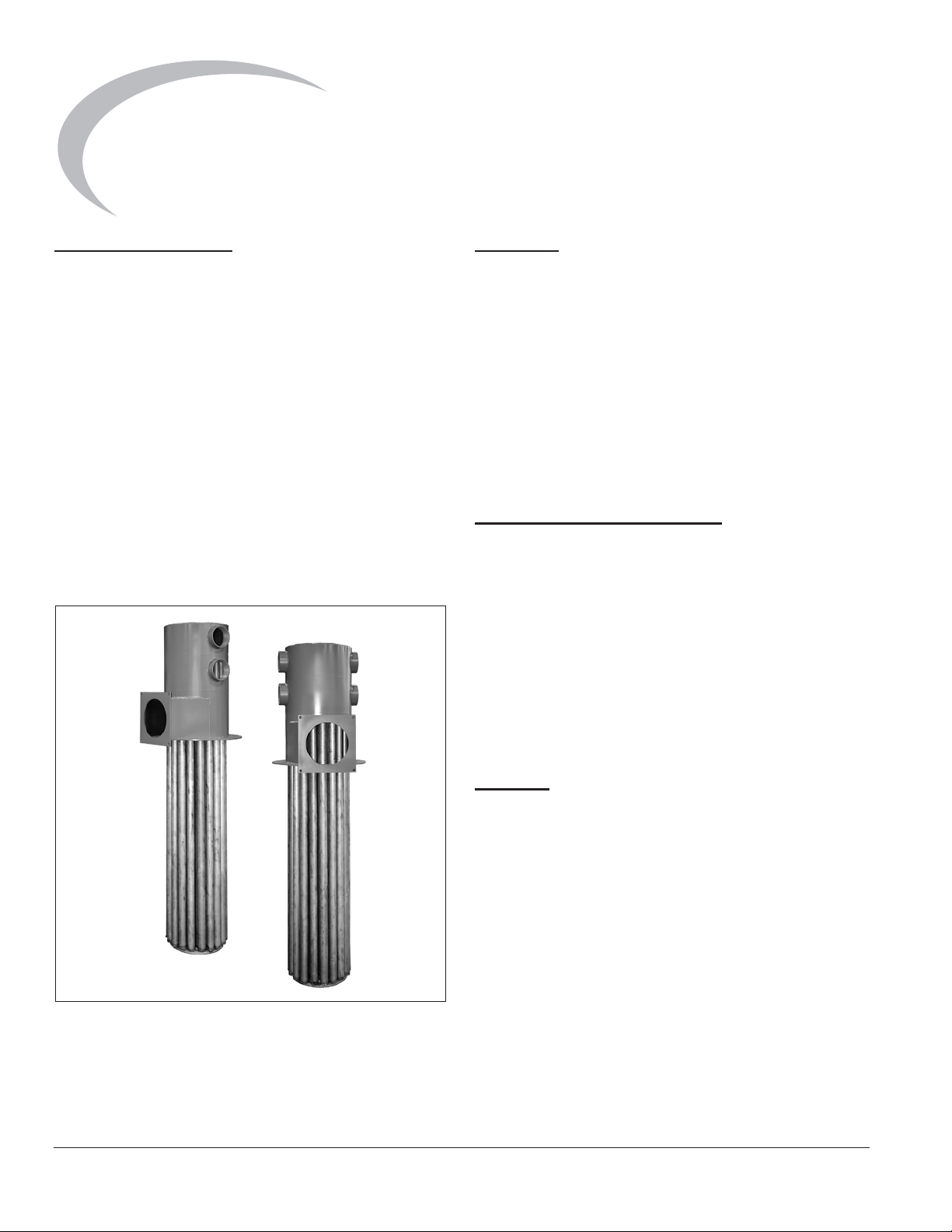
Product Description
The Extern-A-Therm recuperators are compact tubular
air-to-air heat exchangers designed to recover the waste
heat in industrial exhaust gases. The recovered heat is
used to preheat the combustion air for the system’s
burners, thereby increasing the thermal efficiency. To
ensure that all the wasted heat is drawn across the
recuperator tubes, the recuperator is typically mated with
an Eclipse eductor.
The single-ended design of the Extern-A-Therm
recuperator allows for free expansion of the recuperator
tubes; no expansion joints are required.
The design of the Extern-A-Therm, housing and eductor
ensure ease of installation and efficient use of existing
pipe work. The housings are internally insulated; there is
no need for additional external insulation.
Audience
This manual has been written for people who are already
familiar with all aspects of industrial heating equipment
design.
These aspects are:
• Design/Selection
• Use
• Maintenance
The audience is expected to have previous experience
with this type of equipment.
Extern-A-Therm Documents
Design Guide No. 540
• This document
Datasheet, Series No. 540-1 through 540-4
• Available for individual Extern-A-Therm models
• Required to complete design calculations in this
guide
Related Documents
• EFE 825 (Combustion Engineering Guide)
• Eclipse Bulletins and Info Guides: 610, 710, 720,
730, 742, 744, 760, 930
Purpose
The purpose of this manual is to ensure that the design of
a safe, effective, and trouble free system is carried out.
Figure 1.1. Extern-A-Therm Recuperator
4
Eclipse Extern-A-Therm Recuperators, Design Guide 540, 3/9/2009
Page 5

Safety
2
Important notices about safe burner operation will be
found in this section. Read this entire manual before
attempting to start the system. If any part of the
information in this manual is not understood, contact
Eclipse before continuing.
Safety Warnings
WARNING
Ŷ The burner might have HOT surfaces. Always wear
protective clothing when approaching the burner.
NOTICE
Ŷ This manual provides information in the use of
these burners for their specific design purpose. Do
not deviate from any instructions or application
limits described herein without written advice from
Eclipse.
Capabilities
Adjustment, maintenance and troubleshooting of the
mechanical and the electrical parts of this system should
be done by qualified personnel with good mechanical
aptitude and experience with combustion equipment.
Operator Training
The best safety precaution is an alert and trained
operator. Train new operators thoroughly and have them
demonstrate an adequate understanding of the
equipment and its operation. A regular retraining schedule
should be administered to ensure operators maintain a
high degree of proficiency.
Replacement Parts
Order replacement parts from Eclipse only. All Eclipse
approved, customer supplied valves or switches should
carry UL, FM, CSA, CGA, and/or CE approval, where
applicable.
Eclipse Extern-A-Therm Recuperators, Design Guide 540, 3/9/2009
5
Page 6

r
System Design
3
Design
Furnace Temperature Limits
Up to 1800°F - No special safeguards are required to
protect the recuperator. See “Special Precautions for
Aluminum Melting or Holding” on this page, for aluminum
applications.
1800°F - 2100°F - To ensure that the safe operating
temperature of the recuperator tubes is not exceeded, air
flow must not fall below the following limits:
• Model 300 MA - 90 scfh
• Model 600 MA - 180 scfh
• Model 1500 MA - 450 scfh
• Model 2500 MA - 750 scfh
The recuperator must be positioned so that it will not be
exposed to direct radiation from the furnace. This is to
protect the recuperator during shut down or power failure.
CAUTION
Ŷ When shutting a process down, air must be
supplied to the exchanger until the exhaust inlet
temperature falls below 1800°F.
Flue Gas Restrictions
The recuperator must not be used with any chloride,
sulfide, potassium, sodium or lithium salts in the flue gas.
Special Precautions for Aluminum Melting or
Holding
If the recuperator is to be used on aluminum melting
furnaces where flux is used, special precautions must be
taken to protect the recuperator during the fluxing cycle.
When flux is being used, the exit of the eductor should be
closed off and a by-pass duct opened until the fluxing is
complete and no fluxing agents are present in the
exhaust. Closing the damper on the eductor will force the
eductor air back through the recuperator ensuring that no
contaminated exhaust gases enter the recuperator. See
Figure 3.1.
Eductor damper
to be closed
when fluxing
2100°F - 2400°F - Dilution air must be introduced to the air
stream to maintain exhaust temperature below 2100°F.
(See Figure 3.4.) The amount of dilution air can be
determined from the “Dilution Air” section, page 7. When
using dilution air do not operate with excess fuel, either
gas or oil. The resulting fire would destroy the recuperator.
A high temperature protection limit switch must be fitted to
ensure flue temperatures do not exceed 2100°F.
The recuperator must be positioned so that it will not be
exposed to direct radiation from the furnace. This is to
protect the recuperator during shutdown or power failure.
The low flow air requirements listed above must be
observed.
CAUTION
Ŷ When shutting a process down, air must be
supplied to the exchanger until the exhaust inlet
temperature falls below 1800°F.
6
Bypass dampe
to be open
when fluxing
Figure 3.1.
Eclipse Extern-A-Therm Recuperators, Design Guide 540, 3/9/2009
Page 7

In addition when using the recuperators on aluminum
melting or holding furnaces, the exhaust temperature
must be diluted to less than 1300°F (704°C). This will
ensure that any aluminum in the exhaust will condense
out before entering the recuperator. Aluminum
condensing on the recuperator tubes will cause damage.
When in doubt consult Eclipse.
CAUTION
Ŷ Failure to observe these conditions can destroy
the recuperator and will void the warranty.
Determine the Size of Recuperator Required
It is assumed that the net BTU requirement is known. The
table below is an approximate guide for the efficiency with
an Extern-A-Therm recuperator at various furnace
temperatures with 10% excess combustion air. This is
sufficiently accurate to determine the size of recuperator
to use; it should not be used to determine actual gas
usage.
Furnace Temperature
°F (°C)
1500 (815) 70%
1600 (817) 68.5%
1700 (926) 67%
1800 (982) 65.7%
1900 (1037) 64.4%
2000 (1093) 63%
2100 (1148) 60.6%
2200 (1204) 59.3%
2300 (1260) 58%
Calculate the gross BTU requirement using this efficiency,
then check the Extern-A-Therm recuperator capacities in
the datasheet to determine the size of recuperator.
Example:
Net required 1.0 mm BTU/hr with furnace temperature of
1700°F. Using the table above, the efficiency = 67%.
Therefore, the gross input = 1.0mm BTU/hr ÷ 0.67 =
1.49mm BTU/hr. From the datasheets, a 1500 MA
Extern-A-Therm with a capacity of 0.4mm BTU/hr to
1.6mm BTU/hr must be used. If a higher preheated air
temperature is required the 2500 MA should be used.
Extern-A-Therm Recuperator
Dilution Air
If the furnace temperature is above 2100°F dilution air
must be introduced to cool the exhaust gases to 2100°F
before they enter the recuperator.
As a guide, the following chart can be used to determine
the amount of dilution air required.
Efficiency with
Furnace
Temp
°F (°C)
2200
(1204)75(2.1)
2300
(1260)
2400
(1315)
100,000
(29.3)
Burner Capacity BTU/hr (kW)
200,000
(58.6)
(4.3)
150
(4.2)
220
(6.2)
Volume scfh (m
(8.5)
(12.4)
500,000
(146.5)
150
300
440
Table Values for
375
(10.6)
750
(21.2)
1,100
(31.1)
3
/hr) Cooling Air
1,000,000
(293.1)
730
(20.7)
1,500
(42.4)
2,200
(62.3)
2,000,000
(586.1)
1,460
(41.3)
3,000
(84.9)
4,400
(124.6)
Number of Extern-A-Therm Recuperators
It is recommended that one recuperator be used for each
zone of control. This has the advantage that the
combustion air flow is controlled on the cold side of the
recuperator. All the subsequent instructions and
descriptions are written with this assumption. If it is
required that a single Extern-A-Therm recuperator will
pre-heat the combustion air for multiple zones, consult
Eclipse.
Mounting the Recuperator
The Extern-A-Therm recuperators are designed for
vertical mounting with the recuperator tubes hanging
vertically down. If an alternative mounting arrangement is
required, contact Eclipse.
The recuperator and exhaust housings have sufficient
strength to be self supporting from the mounting flange,
and can support the eductor if fitted. Eclipse recommends
the use of flexible piping at the air inlet/outlet and
entrainment air connections to accommodate expansion
and contraction. See Figure 3.2 for a typical arrangement.
Do not add additional insulation to the outside of the
recuperator, as this will damage the unit.
Mounting the Eductor
The eductor can be mounted directly to the recuperator.
The outlet flange on the recuperator is of sufficient
strength to support the weight of the eductor; no additional
support is required for the eductor.
The standard eductor is designed for vertical mounting, if
horizontal mounting is required, consult Eclipse. No
additional exhaust ducting should be connected directly to
the eductor.
There should be no restrictions at the eductor outlet; this
would affect the eductor performance. See Figure 3.3.
The outside of the eductor should not be insulated.
Eclipse Extern-A-Therm Recuperators, Design Guide 540, 3/9/2009
7
Page 8

Eductor
Typical Air Pipe Work
The schematic, Figure 3.4, shows a typical air control
scheme. This uses one control valve to control the
combustion air, eductor air and dilution air. As the burners
turn down, the eductor air lowers to reduce the suction
and keep the furnace at the desired pressure. If dilution air
is necessary, this will also be reduced, so as not to
excessively cool the exhaust gas. A more sophisticated
control, Figure 3.5. This assumes that greater furnace
pressure control is required. The eductor air has a
separate control valve driven by the furnace pressure
control.
Recuperator &
Insulated Housing
Exhaust
Dilution
Air
Figure 3.2.
Flue
Flue
Break
Thermocouple
Support
Structure
By Customer
Eductor
Air
Over -
temperature
More details of the combustion circuits and methods of
controlling the air and gas can be found in Design Guide
206 covering ThermJet Burners for Preheated
Combustion Air.
Eductor Air Flow
Eductors are designed to overcome the exhaust gas
pressure drop through the recuperator. The eductor
airflows given in the datasheet are the flows required to
overcome the exhaust pressure drop at the maximum
rating of the recuperator and an inlet exhaust temperature
of 1900°F (1037°C). The entrainment air flow required will
be different at other capacities or exhaust temperatures.
Cleaning the Recuperator
Dirt or other substances in the exhaust can accumulate on
the outside of the recuperator tubes. Units can be cleaned
with steam, compressed air, or any other method that
accomplishes the task without damaging the insulation.
Eductor
Eductor
Air
Figure 3.3.
8
Eclipse Extern-A-Therm Recuperators, Design Guide 540, 3/9/2009
Page 9

Eductor Air
Combustion Air
Dilution Air
(if Required)
Exhaust Gas
Preheated
Combustion
Air to
Burners
Preheated
Combustion
Air to
Burners
Figure 3.4. P & ID of Typical Piping
Eductor Air
Combustion Air
Dilution Air
(if Required)
Exhaust Gas
Figure 3.5. P & ID of Typical Piping for Greater Furnace Pressure Control
Preheated
Combustion
Air to
Burners
Preheated
Combustion
Air to
Burners
Eclipse Extern-A-Therm Recuperators, Design Guide 540, 3/9/2009
9
Page 10

Appendix
Conversion Factors
Metric to English
From To Multiply By
cubic meter (m³) cubic foot (ft³) 35.31
cubic meter/hr (m³/h) cubic foot/hr (cfh) 35.31
degrees Celsius (°C) degrees Fahrenheit (°F) (°C x 9/5) + 32
kilogram (kg) pound (lb) 2.205
kilowatt (kW) BTU/hr 3414
meter (m) foot (ft) 3.28
millibar (mbar) inches water column ("w.c.) 0.401
millibar (mbar) pounds/sq in (psi) 14.5 x 10
millimeter (mm) inch (in) 3.94 x 10
MJ/Nm³ BTU/ft³ (standard) 2.491 x 10
Metric to Metric
kiloPascals (kPa) millibar (mbar) 10
meter (m) millimeter (mm) 1000
millibar (mbar) kiloPascals (kPa) 0.1
millimeter (mm) meter (m) 0.001
-3
-2
-2
From To Multiply By
English to Metric
cubic foot (ft3) cubic meter (m3)
cubic foot/hour (cfh) cubic meter/hour (m3/h)
degrees Fahrenheit (°F) degrees Celsius (°C) (°F - 32) ÷ 5/9
inches water column ("w.c.) millibar (mbar) 2.49
pounds/sq in (psi) millibar (mbar) 68.95
BTU/ft³ (standard) MJ/Nm³ 40.14
Design Guide 540 3/9/2009
From To Multiply By
BTU/hr kilowatt (kW)
foot (ft) meter (m) 0.3048
inch (in) millimeter (mm) 25.4
pound (lb) kilogram (kg) 0.454
0.293 x 10
2.832 x 10
2.832 x 10
-3
-2
-2
Page 11

Offered By:
Power Equipment Company
2011 Williamsburg Road
Richmond, Virginia 23231
Phone (804) 236-3800
Fax (804) 236-3882
www.peconet.com
 Loading...