

Page 1

USER MANUAL
MANUAL DE INSTRUCCIONES
NOTICE D’EMPLOI
BEDIENUNGSANLEITUNG
MPA4-80
MPA6-80
C
L
E
R
AUDIO CREATIVE POWER
Page 2

2
Page 3

3
MPA4-80 / MPA6-80 USER MANUAL
1. IMPORTANT REMARK 04
2. INTRODUCTION 04
3. INSTALLATION 05
3.1. Placement and mounting 05
3.2. Mains connection 06
3.3. Ground Link switch 06
3.4. Multi-function 06
3.5. Input connections 07
3.6. Output connections 08
4. OPERATION AND USAGE 08
4.1. Start up 08
4.2. Input attenuation 08
4.3. Indicators 09
5. CLEANING 09
6. DIAGRAMS 31
6.1. Technical characteristics 31
6.2. MPA4-80 input options 32
6.3. MPA6-80 input options 34
6.4. MPA4-80 output options 36
6.5. MPA6-80 output options 37
6.6. Function list 38
6.7. Function diagram 40
6.8. Block diagram 41
All numbers subject to variation due to production tolerances. ECLER S.A. reserves the right to make
changes or improvements in manufacturing or design which may affect specifications.
Page 4

4
1. IMPORTANT REMARK
Congratulations! You are the owner of a carefully designed and manufactured
equipment. We thank you for having purchased our MPA4-80 or MPA6-80 power amplifier.
It is VERY IMPORTANT that you read this manual before connecting the amplifier in
order to obtain its maximum performance.
We recommend our authorised Technical Services whenever any maintenance task
should be needed so that optimum operation shall be achieved.
2. INTRODUCTION
The MPA4-80 amplifier station consists of four 77W/4Ω amplifiers, which can be
configured through a set of switches found on the rear panel. This allows multiple amplification
setups useful in many situations, for example:
Four mono amplifiers for four different mono inputs.
When setup this way, the MPA4-80 is able to amplify four different audio signals, each one
having a dedicated volume control.
Four mono amplifiers for one common mono input.
The amplifier operates now with just one input signal for all amplifiers, but preserves the ability
to control each channels volume independently. This setup is useful when distributing signals to
different zones.
Four mono amplifiers for one common stereo input.
This setup is similar to the previous example but the input is now a stereo signal. The amplifier
adds both stereo channels together converting them into a mono signal.
Two stereo amplifiers for two different stereo inputs.
Each stereo channel offers a dedicated volume control. Useful for addressing two zones with
two different stereo signals.
Two stereo amplifiers for one common stereo input.
This setup is similar to the previous example but the input is now a single stereo signal which is
fed to both amplifiers.
Two bridged amplifiers for two different mono inputs.
Now you get a typical stereo amplifier configuration. With a bridged amplifier you obtain
doubled output power with a load of at least 8Ω.
Two bridged amplifiers for a common mono input.
The MPA operates now with a single mono signal for two mono amplifiers, each one with its
own volume control
Two bridged amplifiers for a common stereo input.
This setup is similar to the previous example but the input is now a stereo signal. The amplifier
adds both stereo channels together converting them into a mono signal.
Two mono amplifiers and one bridged amplifier for one common mono input.
Useful for bi-amplified setups, with two amplifiers for mid-range speakers and tweeters and a
third (bridged) amplifier for a subwoofer. (This amplifier does not include any filtering)
Page 5

5
The MPA6-80 amplifier station consists of six 75W/4Ω amplifiers, which can be
configured through a set of switches found on the rear panel. This allows multiple amplification
setups useful in many situations, for example:
Six mono amplifiers for six different mono inputs.
When setup this way, the MPA is able to amplify six different audio signals, each one having a
dedicated volume control.
Six mono amplifiers for one common mono input.
The amplifier operates now with just one input signal for all amplifiers, but preserves the ability
to control each channel volume independently. This setup is useful when distributing signals to
different zones.
Six mono amplifiers for one common stereo input.
This setup is similar to the previous example but the input is now a stereo signal. The amplifier
adds both stereo channels together converting them into a mono signal.
Three stereo amplifiers for three different stereo inputs.
Each stereo channel offers a dedicated volume control. Useful for addressing three zones with
three different stereo signals.
Three stereo amplifiers for one common stereo input.
This setup is similar to the previous example but the input is now a single stereo signal which is
fed to both amplifiers.
Three bridged amplifiers for three different mono inputs.
Now you get a typical stereo amplifier configuration. With a bridged amplifier you obtain
doubled output power with a load of at least 8Ω.
Three bridged amplifiers for a common mono input.
The MPA operates now with a single mono signal for three mono amplifiers, each one with its
own volume control
Three bridged amplifiers for a common stereo input.
This setup is similar to the previous example but the input is now a stereo signal. The amplifier
adds both stereo channels together converting them into a mono signal.
Four mono amplifiers and one bridged amplifier for one common mono input.
Useful for setups with four amplifiers for mid-range speakers and tweeters and an extra
(bridged) amplifier for a subwoofer. (This amplifier does not include any filtering)
3. INSTALLATION
3.1. Placement and mounting
The amplifier is a 2 RU high 19'' rack module. It is supplied with plastic washers in
order not to damage the unit when tightening the screws.
It is important that the amplifier, as a heat source, is not placed next to other
equipment nor exposed to high temperatures.
Page 6

6
3.2. Mains connection
The MPA amplifiers are fed with alternate currents, depending on the country, of
110-120, 220-240V 50/60Hz (see characteristics in the back of the unit). The power
consumption at maximum performance is 370 VA for the MPA4-80 and 520 VA for the
MPA6-80. It's important that your mains installation is adequately scaled to these power
demands.
You should provide the device with a suitable earth connection, Rg= 30Ω or less
The environment should be dry and completely dust-free
When connecting / disconnecting cables or doing other manipulation always pull out
the mains supply cable
You should avoid that the supply cable twists with the shielded signal cables, as this
could lead to unwanted hum.
In order to protect the units from an eventual electrical overload or momentary power
peaks from the internal circuits they carry a T4 A or T6.3 A fuse (34) (MPA4-80 and
MPA6-80 respectively). Should it ever blow up, unplug the unit from mains and
replace it with an identical one. If the new fuse blows again contact immediately with our
Authorized Technical Service. YOU MUST NEVER USE A HIGHER VALUE FUSE.
3.3 Ground Link switch
The “GND LINK” switch (35) purpose is to avoid ground loops caused when several
devices in the same amplification chain are connected to earth simultaneously. This switch
disconnects the electrical ground from the mechanical ground on the housing. In case of a
ground loop (humming noise) operate this switch or alternatively the corresponding switches on
the other devices connected to the chain.
3.4 Multi-function
Depending on the input switches on the MPA4-80 (39, 40, 41, 42, 43, 44), located on the rear
panel, four different amplification configurations can be achieved:
- Four mono amplifiers with following possibilities:
Four different mono inputs
One common mono input for all
One common stereo input for all
- Two stereo amplifiers with following possibilities:
Two different stereo inputs
One single stereo input for both
- Two bridged amplifiers with following possibilities:
Two different mono inputs
One common mono input
One common stereo input
- Combinations between mono, stereo and bridged amplifiers
Page 7

7
Depending on the input switches on the MPA6-80 (36, 37, 38, 39, 40, 41, 42, 43, 44),
located on the rear panel, four different amplification configurations can be achieved:
- Six mono amplifiers with following possibilities:
Six different mono inputs
One common mono input for all
One common stereo input for all
- Three stereo amplifiers with following possibilities:
Three different stereo inputs
One single stereo input for both
- Three bridged amplifiers with following possibilities:
Three different mono inputs
One common mono input
One common stereo input
- Combinations between mono, stereo and bridged amplifiers
3.5. Input connections
The signal input connections on the MPA4-80 (29, 30, 31, 32) and MPA6-80
(27, 28, 29, 30, 31, 32) are electronically balanced XLR-3 sockets, with an input impedance
higher than 20kΩ and a nominal sensitivity of 0dBV(1V). Pin assignment:
1. GROUND
2. PHASE (in phase with the output)
3. NON PHASE (inverted phase)
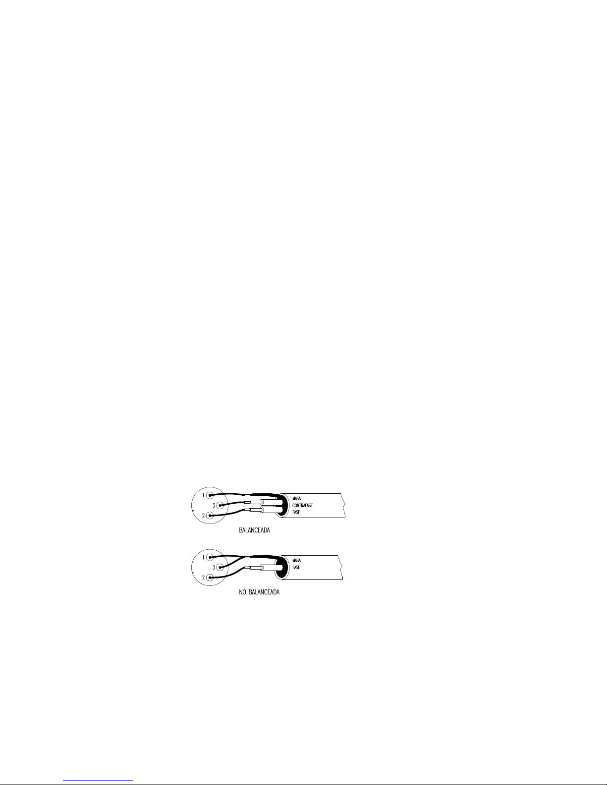
The following diagram shows the connection of balanced and non-balanced audio
sources:
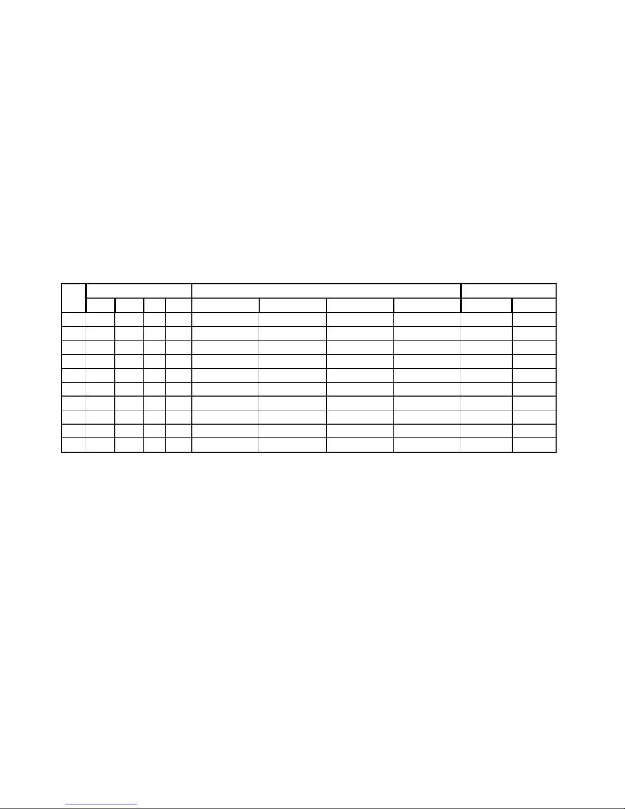
Some of the connection options for the MPA4-80 and the corresponding switch
settings are described later in paragraph 6.2. (paragraph 6.3. for MPA6-80)
Depending on the chosen option, the SP indicators will only light for the active
channels.
Page 8

8
3.6. Output connections
The output section on the MPA4-80 rear panel holds 8 screw-type speaker terminals
(23, 24, 25, 26), two for each amplifier.
The attenuation controls and the output configurations are described later in
paragraph 6.4.
The output section on the MPA6-80 rear panel holds 12 screw-type speaker terminals
(21, 22, 23, 24, 25, 26), two for each amplifier.
The attenuation controls and the output configurations are described later in
paragraph 6.5.
The cable which connects the speakers to the amplifier should be high quality and as
short and thick as possible. This is important when covering long distances; for up to 10m we
recommend a cable section not smaller than 2.5mm². For longer distances we recommend
4mm².
Remember that the minimum load impedance for stereo or mono amplifiers is 4Ω. In
bridged mode the impedance must be not less than 8Ω. For a reliable operation under any
circumstance connect lower load impedances than just specified.
Attention: In bridged mode, use only the red terminals.
4. OPERATION AND USAGE
4.1. Start up
To switch the unit on just push the switch labelled POWER (19) and the integrated
green pilot light will light up. We highly recommend the "safe power up sequence": First the
sound sources, then mixer, equalizers and active filters and, finally, power amplifiers. Powering
off should be done by following the exact reverse sequence in order to avoid any possible
peaks reaching the next device, and consequently protecting the loudspeakers, which are
specially sensitive to these peaks.
4.2. Input attenuation
These are rotary potentiometers located on the front panel (1, 4, 7, 10 on the
MPA4-80 and 1, 4, 7, 10, 13, 16 on the MPA6-80).
These attenuators allow the connection of different mixers, an independent volume
control and the connection of speakers not able to handle the amplifiers maximum output
power, thus avoiding the risk of damaging them with the mixers or preamps volume control.
Inside the device's packaging you will find a little plastic bag containing 4/6
transparent caps which protect the input attenuation settings from unwanted manipulation.
These caps are transparent in order to let you visualize the current settings.
Once inserted, they cannot be removed with bare fingers, for this purpose, a small screwdriver
is needed.
Page 9

9
4.3. Indicators
The “SP” signal presence indicators (2, 5, 8, 11 on the MPA4-80 and 2, 5, 8, 11, 14, 17 on
the MPA6-80) light up when the input signal reaches approximately -40dBV.
The “CLIP” indicators (3, 6, 9, 12 on the MPA4-80 and 3, 6, 9, 12, 15, 18 on the
MPA6-80) light up when the output signal for the speakers is -1.5 dB below the actual clipping
threshold. This clipping system watches for eventual supply voltage variations, thus giving
always an accurate clipping indication, regardless of mains voltage deviations. It is normal that
when operating at high output power, the CLIP indicators light up in synchronisation with the
low frequencies, which carry the most energy. Nevertheless, you should avoid that the CLIP
indicators are lit continuously
5. CLEANING
The control panel must not be cleaned with any dissolvent, abrasive or petroleum
derivate substance else paint and silk printing could be damaged.
Whenever cleaning should be necessary use a soft cloth slightly wet with water and
neutral liquid soap or with a solution of water and alcohol at 50%. Be careful that no liquid gets
into the mixer. Never use sharp or erosive objects to scratch the control panel.
Should any liquid get into the amplifier, do not use any cleaning sprays; send the unit
to the nearest ECLER Technical Service.
Page 10

10
MANUAL DE INSTRUCCIONES MPA4-80 / MPA6-80
1. NOTA IMPORTANTE 11
2. INTRODUCCIÓN 11
3. INSTALACIÓN 12
3.1. Ubicación y montaje 12
3.2. Conexión a red 13
3.3. Conmutador “Ground Link” 13
3.4. Multifunción 13
3.5. Conexiones de entrada 14
3.6. Conexiones de salida 15
4. OPERACIÓN Y USO 15
4.1. Puesta en funcionamiento 15
4.2. Atenuadores de entrada 15
4.3. Indicadores 16
5. LIMPIEZA 16
6. DIAGRAMAS 31
6.1. Características técnicas 31
6.2. Opciones de entrada MPA4-80 32
6.3. Opciones de entrada MPA6-80 34
6.4. Opciones de salida MPA4-80 36
6.5. Opciones de salida MPA6-80 37
6.6. Lista de funciones 38
6.7. Diagrama de funcionamiento 40
6.8. Diagrama de bloques 41
Todos los datos están sujetos a variación debida a tolerancias de producción. ECLER S.A. se reserva el
derecho de realizar cambios o mejoras en la fabricación o diseño que pudieran afectar las especificaciones.
Page 11

11
1. NOTA IMPORTANTE
¡Enhorabuena!. Vd. posee el resultado de un cuidadoso diseño y una esmerada
fabricación. Agradecemos su confianza por haber elegido nuestra etapa de potencia
MPA4-80 / MPA6-80.
Para conseguir la máxima operatividad del aparato y su máximo rendimiento, es MUY
IMPORTANTE antes de su conexión, leer detenidamente y tener muy presentes las
consideraciones que en este manual se especifican.
Para garantizar el óptimo funcionamiento de este aparato, recomendamos que su
mantenimiento sea llevado a cabo por nuestros Servicios Técnicos autorizados.
2. INTRODUCCIÓN
La estación de amplificación MPA4-80 está formada por cuatro amplificadores de
77W/4Ω configurables mediante los conmutadores situados en el panel posterior, permitiendo
múltiples posibilidades de trabajo de entre las que destacamos:
4 Amplificadores en mono para 4 señales mono diferentes.
De esta forma el MPA está preparado para trabajar con cuatro señales distintas disponiendo
cada una de ellas de su propio control de volumen.
4 Amplificadores en mono con una entrada en común.
El amplificador trabaja solamente con una señal de entrada pero conserva la posibilidad de
ajustar de forma independiente el nivel de cada uno de los cuatro canales, es una aplicación
ideal para realizar una distribución de sonido a distintas zonas.
4 Amplificadores en mono con una entrada en estéreo común.
Aplicación idéntica a la anterior pero teniendo como entrada una fuente de sonido estéreo, el
amplificador realiza la suma de los dos canales de la fuente para convertirla en una señal mono.
2 Amplificadores estéreo con dos entradas estéreo diferentes.
Disponiendo cada una de ellas del control de volumen de cada canal estéreo. Útil para sonorizar
dos zonas con dos señales estéreo diferentes.
2 Amplificadores estéreo con entrada estéreo común.
Aplicación idéntica a la anterior pero con la misma señal estéreo de entrada en los dos
amplificadores.
2 Amplificadores en puente con dos señales mono diferentes.
Disponemos de un amplificador estéreo convencional. Con un amplificador trabajando en puente
obtendremos el doble de potencia con una impedancia de carga mínima de 8Ω.
2 Amplificadores en puente con una señal mono en común.
El MPA trabaja con una sola señal de entrada para dos amplificadores mono con posibilidad de
controlar los volúmenes de forma independiente.
2 Amplificadores en puente con una entrada estéreo común.
Aplicación idéntica a la anterior pero teniendo como entrada una fuente de sonido estéreo, el
amplificador realiza la suma de los dos canales de la fuente para convertirla en una señal mono.
2 Amplificadores mono y 1 amplificador en puente con una entrada mono común.
Útil para instalaciones con dos amplificadores con cajas de medios y agudos y el tercer
amplificador en puente para una caja de subgraves. (Este amplificador no incorpora ningún tipo
de filtro).
Page 12

12
En cambio, la estación de amplificación MPA6-80 está formada por seis
amplificadores de 75W/4Ω configurables mediante los conmutadores situados en el panel
posterior, permitiendo múltiples posibilidades de trabajo de entre las que destacamos:
6 Amplificadores en mono para 6 señales mono diferentes.
De esta forma el MPA está preparado para trabajar con seis señales distintas disponiendo cada
una de ellas de su propio control de volumen.
6 Amplificadores en mono con una entrada en común.
El amplificador trabaja solamente con una señal de entrada pero conserva la posibilidad de
ajustar de forma independiente el nivel de cada uno de los seis canales, es una aplicación ideal
para realizar una distribución de sonido a distintas zonas.
6 Amplificadores en mono con una entrada en estéreo común.
Aplicación idéntica a la anterior pero teniendo como entrada una fuente de sonido estéreo, el
amplificador realiza la suma de los dos canales de la fuente para convertirla en una señal mono.
3 Amplificadores estéreo con tres entradas estéreo diferentes.
Disponiendo cada una de ellas el control de volumen de cada canal del estéreo. Útil para
sonorizar tres zonas con tres señales estéreo diferentes.
3 Amplificadores estéreo con entrada estéreo común.
Aplicación idéntica a la anterior pero con la misma señal estéreo de entrada en los tres
amplificadores.
3 Amplificadores en puente con tres señales mono diferentes.
Podremos disponer de tres zonas con tres señales mono diferentes y con posibilidad de ajustar
el volumen de forma independiente en cada una de ellas. Con un amplificador trabajando en
puente obtendremos el doble de potencia con una impedancia de carga mínima de 8Ω.
3 Amplificadores en puente con una señal mono en común.
El MPA trabaja con una sola señal de entrada para tres amplificadores mono con posibilidad de
controlar los volúmenes de forma independiente.
3 Amplificadores en puente con un entrada estéreo común.
Aplicación idéntica a la anterior pero teniendo como entrada una fuente de sonido estéreo, el
amplificador realiza la suma de los dos canales de la fuente para convertirla en una señal mono.
4 Amplificadores mono y 1 amplificador en puente con una entrada mono común.
Útil para instalaciones donde se necesiten 4 amplificadores de una potencia determinada (para
cajas de medios y agudos) y un amplificador en puente con más potencia de salida (para caja
de subgraves, este amplificador no incorpora ningún tipo de filtro).
3. INSTALACIÓN
3.1. Ubicación y montaje
El amplificador se presenta en módulo rack de 19" y dos unidades de altura, se
suministra con arandelas de plástico con el fin de poderlo montar en un rack sin dañar el aparato.
Es muy importante que, como elemento generador de calor que es, el amplificador no
esté completamente encerrado ni expuesto a temperaturas extremas.
Page 13

13
3.2. Conexión a red
El amplificador se alimenta con corriente alterna, según el país, de 110-120, 220-240V
50/60Hz. (ver placa de características en el aparato), su consumo a plena potencia es de 370VA
en el caso del MPA4-80 y de 520VA en el caso del MPA6-80, por ello es importante que la
instalación de red sea la adecuada a tal consumo.
Debe conectarse a una toma de tierra en condiciones (Resistencia de tierra, Rg=30Ω o
menos).
El ambiente de trabajo deberá ser seco y estar totalmente libre de polvo.
En caso de requerir alguna intervención y / o conexión - desconexión del amplificador
debe desconectarse previamente la alimentación.
Debe evitarse que el cable de red se entremezcle con los cables blindados que
transportan la señal de audio, ya que ello podría ocasionar zumbidos.
Para proteger al amplificador de eventuales sobrecargas en la línea de red o bien excesos
ocasionales en el consumo de los circuitos internos, está provisto de un fusible de red de
T4 A en el caso del MPA4-80 y de T6.3 A en el caso del MPA6-80 (34). En caso de que
éste se fundiera se desconectaría el aparato y se sustituiría por otro de idénticas características. Si
éste último se volviera a fundir, consulte con nuestro Servicio Técnico. EN NINGÚN CASO DEBE
PONERSE UN FUSIBLE DE VALOR MÁS ELEVADO.
3.3. Conmutador Ground Link
El conmutador “GND LINK” (35) tiene por misión evitar la creación de bucles de masa,
originados cuando se conectan a tierra varios aparatos integrantes de una misma cadena de forma
simultánea. Este conmutador permite la desconexión de la masa eléctrica del circuito de la masa
del chasis. En caso de producirse zumbidos actuar alternativamente sobre el conmutador del
amplificador y demás elementos de la cadena de audio.
3.4. Multifunción
En el MPA4-80 según la posición de los conmutadores de entrada
(39, 40, 41, 42, 43, 44) situados en el panel posterior dispondremos de 4 funciones diferentes de
amplificación:
- Cuatro amplificadores en mono, con posibilidad de:
Cuatro entradas en mono distintas.
Una misma entrada en mono para todos.
Una señal en estéreo común para todos.
- Dos amplificadores en estéreo, con posibilidad de:
Dos entradas en estéreo diferentes.
Una sola entrada en estéreo común para los dos.
- Dos amplificadores en puente, con posibilidad de:
Dos entradas en mono diferentes.
Una entrada en mono en común.
Una entrada en estéreo común.
- Combinación entre amplificadores mono, estéreo y puente.
Page 14
14
Tratándose del MPA6-80 según la posición de los conmutadores de entrada
(36, 37, 38, 39, 40, 41, 42, 43, 44) situados en el panel posterior dispondremos de la posibilidad
de 4 funciones diferentes de amplificación:
- Seis amplificadores en mono, con posibilidad de:
Seis entradas en mono distintas.
Una misma entrada en mono para todos.
Una señal en estéreo común para todos.
- Tres amplificadores en estéreo, con posibilidad de:
Tres entradas en estéreo diferentes.
Una sola entrada en estéreo común para los tres.
- Tres amplificadores en puente, con posibilidad de:
Tres entradas en mono diferentes.
Una entrada en mono en común
Una entrada en estéreo común.
- Combinación entre amplificadores mono, estéreo y puente.
3.5. Conexiones de entrada
Las entradas de señal en la MPA4-80 (29, 30, 31, 32) y en la MPA6-80 (27, 28, 29,
30, 31, 32) son del tipo XLR-3 balanceadas electrónicamente, con una impedancia de entrada
superior a 20kΩ y una sensibilidad nominal de 0dBV(1V). La asignación es la siguiente:
1.- GROUND (masa)
2.- PHASE (señal en fase con la salida)
3.- NON PHASE ( señal en contrafase con la salida)
Se esquematiza a continuación la conexión de las entradas, según se trate de atacarlas
con una fuente de sonido con línea balanceada o no balanceada:
Algunas de las opciones de conexionado de la MPA4-80 y la posición de los
conmutadores de cada una de ellas se detallan en el apartado 6.2. y para la MPA6-80 en el
apartado 6.3.
Dependiendo de la opción escogida, los indicadores de señal “SP” lucirán solamente en
los canales que estén activos.
Page 15

15
3.6. Conexiones de salida
La sección “OUTPUT” del panel posterior del MPA4-80 está provista de 8 terminales
atornillables (23, 24, 25, 26), dos por amplificador.
Los controles de atenuación y conexionado de las salidas se detallan en el apartado 6.4.
En el caso del MPA6-80 la sección “OUTPUT” del panel posterior está provista de 12
terminales atornillables (21,22, 23, 24, 25, 26), dos por amplificador.
Los controles de atenuación y conexionado de las salidas se detallan en el apartado 6.5.
El cable de conexión que une las salidas del amplificador y los altavoces deberá ser de
buena calidad, de suficiente sección y lo más corto posible. Esto tiene especial importancia
cuando las distancias a cubrir son grandes; hasta 10m se recomienda una sección no inferior a
2.5mm2 y para distancias superiores 4mm2.
Recuerde que la impedancia mínima de trabajo para los amplificadores en mono o
estéreo es de 4Ω, y trabajando en modo puente será de 8Ω. Para un buen funcionamiento del
aparato bajo ningún motivo se ha de trabajar con impedancias menores a las especificadas
anteriormente.
Atención: en modo puente solo debe utilizar los terminales rojos.
4. OPERACIÓN Y USO
4.1. Puesta en funcionamiento
Esta se realizará mediante el interruptor de red POWER (19) e inmediatamente se
iluminará el piloto verde integrado en el propio interruptor. Siempre resulta muy recomendable
poner en marcha todos los aparatos siguiendo la secuencia siguiente: Fuentes de sonido, unidad
de mezclas, ecualizadores, filtros activos y finalmente amplificadores de potencia. El paro de los
aparatos debe realizarse en la secuencia inversa. Siguiendo este orden los picos o transitorios
producidos por el encendido o apagado de los aparatos no afecta a los siguientes, y por
consiguiente tampoco llegan a los altavoces, elementos extremadamente susceptibles de averiarse
en estos casos.
4.2. Atenuadores de entrada
Están constituidos por sendos potenciómetros rotativos, situados en el panel frontal
(1, 4, 7, 10 para el MPA4-80 y 1, 4, 7, 10, 13, 16 en el caso del MPA6-80).
Estos atenuadores posibilitan la conexión a distintos tipos de mesas, regulación de nivel
independiente y conexión de altavoces que soporten una potencia inferior a la suministrada por el
amplificador a pleno rendimiento, sin peligro de dañarlos por un descuido al manejar el volumen
del preamplificador-mezclador.
En la caja del aparato encontrará una bolsita con 4/6 tapones transparentes que tienen
como cometido proteger los ajustes de atenuación de entrada de maniobras no deseadas. Estos
tapones son transparentes con el fin de poder visualizar el ajuste realizado.
Una vez insertados no pueden ser retirados con los dedos, siendo necesario utilizar un
pequeño destornillador para este cometido.
Page 16

16
4.3. Indicadores
Indicador de presencia de señal “SP” (2, 5, 8 y 11 en el caso del MPA4-80 y
2, 5, 8, 11, 14 y 17 para el MPA6-80), advierten de la presencia de señal en las entradas del
amplificador. Se encienden cuando el nivel a la entrada es mayor de -40dBV aproximadamente.
Indicadores “CLlP” (3, 6, 9 y 12 para el MPA4-80 y 3, 6, 9, 12, 15 y 18 para el
MPA6-80), se iluminan cuando la señal entregada a los altavoces está a -1.5dB del recorte real.
Este sistema de CLIP tiene en cuenta las posibles variaciones en la tensión de alimentación, dando
siempre una indicación real aunque la red eléctrica varíe. Es normal que trabajando a niveles
elevados de potencia los indicadores de CLIP se iluminen al ritmo de las frecuencias graves, que
son las que poseen mayor contenido energético. Debe procurarse que estos indicadores no
queden iluminados de una forma permanente.
5. LIMPIEZA
El panel de mandos no deberá limpiarse con ninguna sustancia disolvente, abrasiva, o
derivada del petróleo; ya que se corre el riesgo de deteriorar la pintura y serigrafía.
Para su limpieza emplearemos un paño ligeramente humedecido en agua y un poco de
jabón líquido, o bien con una disolución de agua y alcohol a partes iguales. Debe tenerse siempre
la precaución de que no caiga líquido por ninguno de los orificios del aparato. Nunca utilizaremos
para “rascar” la placa de mandos objetos punzantes o erosivos.
Si en algún caso entrase algún líquido por los orificios del aparato evitaremos la
utilización de “sprays” limpiadores y acudiremos al Servicio Técnico ECLER más próximo.
Page 17

17
NOTICE D'EMPLOI MPA4-80 / MPA6-80
1. NOTE IMPORTANTE 18
2. INTRODUCTION 18
3. INSTALLATION 19
3.1. Situation et montage 19
3.2. Branchement 20
3.3. Commutateur “Ground link” 20
3.4. Multifonction 20
3.5. Branchement de l'entrée du signal 21
3.6. Branchement de sortie 22
4. MISE EN MARCHE ET UTILISATION, FONCTIONNEMENT 22
4.1. Mise en marche 22
4.2. Atténuateurs d'entrée 22
4.3. Indicateurs 23
5. ENTRETIEN 23
6. SCHÉMAS 31
6.1. Caractéristiques techniques 31
6.2. Options d’entrée MPA4-80 32
6.3. Options d’entrée MPA6-80 34
6.4. Options de sortie MPA4-80 36
6.5. Options de sortie MPA6-80 37
6.6. Liste de fonctions 39
6.7. Schéma de fonctionnement 40
6.8. Blocs de diagrammes 41
ECLER se réserve le droit d’apporter des modifications de toute sorte sur ses produits qui peuvent altérer
leurs spécifications.
Page 18

18
1. NOTE IMPORTANTE
Félicitations ! Vous avez en votre possession le résultat d’un design et d’une fabrication
particulièrement soignée. Nous vous remercions de la confiance que vous nous portez en
choisissant notre amplificateur MPA4-80 / MPA6-80.
Pour obtenir le meilleur résultat de cet appareil, il est important de lire attentivement les
instructions ci-dessous avant de le brancher.
Pour obtenir le meilleur rendement de cet appareil, il est important que l’entretien soit
réalisé par notre Service Technique Ecler.
2. INTRODUCTION
L’unité d’amplification MPA4-80 comprend quatre amplificateurs de 77W/4Ω,
configurables par les commutateurs situés sur la façade arrière de l’amplificateur, et permet de
travailler de multiples façons :
4 amplificateurs mono avec 4 entrées mono différentes
De cette façon, le MPA peut amplifier 4 signaux audio différents qui auront chacun leur réglage
de volume.
4 amplificateurs mono avec une entrée commune
Le MPA ici fonctionne avec une seule entrée pour tous les amplificateurs mais préserve toujours
la possibilité de contrôler chaque volume indépendamment. Cette configuration est intéressante
pour la distribution de signaux à des zones différentes.
4 amplificateurs mono avec une entrée stéréo commune
Le fonctionnement est identique au précédent mais l’entrée est un signal stéréo. L’amplificateur
prend les deux canaux pour les convertir en signal mono.
2 amplificateurs stéréo avec deux entrées stéréo différentes
Chaque voie stéréo a son propre contrôle de volume. Ceci est très pratique pour adresser deux
signaux différents à deux zones.
2 amplificateurs stéréo avec une entrée stéréo commune
Le fonctionnement est identique au précédent mais avec un seul signal stéréo en entrée pour
les deux amplificateurs.
2 amplificateurs bridgés avec deux entrées mono différentes
Vous obtenez ici un amplificateur stéréo conventionnel. Avec un amplificateur bridgé, on double
la puissance avec une impédance de charge minimale de 8Ω.
2 amplificateurs bridgés avec une entrée mono commune
L’amplificateur MPA travaille maintenant avec un seul signal mono pour deux amplificateurs,
chacun avec son propre contrôle de volume.
2 amplificateurs bridgés avec une entrée stéréo commune
Application identique à la précédente mais l’entrée est maintenant un signal stéréo.
L’amplificateur prend les deux canaux pour les convertir en signal mono.
2 amplificateurs mono et un bridgé avec une entrée mono commune
Intéressant pour les bi-amplifications, avec deux amplificateurs pour les médiums et les aigus et
un troisième amplificateur (bridgé) pour les basses. (Cet amplificateur n’incorpore aucun type de
filtre).
Page 19

19
L’unité d’amplification MPA6-80 comprend six amplificateurs de 75W/4Ω,
configurables par les commutateurs situés sur la façade arrière de l’amplificateur, et permet de
travailler de multiples façons :
6 amplificateurs mono avec 6 entrées mono différentes
De cette façon, le MPA peut amplifier 6 signaux audio différents qui auront chacun leur réglage
de volume.
6 amplificateurs mono avec une entrée commune
Le MPA ici fonctionne avec une seule entrée pour tous les amplificateurs mais préserve toujours
la possibilité de contrôler chaque volume indépendamment. Cette configuration est intéressante
pour la distribution de signaux à des zones différentes.
6 amplificateurs mono avec une entrée stéréo commune
Le fonctionnement est identique au précédent mais l’entrée est un signal stéréo. L’amplificateur
prend les deux canaux pour les convertir en signal mono.
3 amplificateurs stéréo avec trois entrées stéréo différentes
Chaque voie stéréo a son propre contrôle de volume. Ceci est très pratique pour adresser trois
signaux différents à trois zones.
3 amplificateurs stéréo avec une entrée stéréo commune
Le fonctionnement est identique au précédent mais avec un seul signal stéréo en entrée pour
les trois amplificateurs.
3 amplificateurs bridgés avec trois entrées mono différentes
On peut travailler sur 3 zones avec 3 signaux mono différents et chacun avec son propre
contrôle de volume. Avec un amplificateur bridgé, on double la puissance avec une impédance
de charge minimale de 8Ω.
3 amplificateurs bridgés avec une entrée mono commune
L’amplificateur MPA travaille maintenant avec un seul signal pour trois amplificateurs mono
bridgés, chacun avec son propre contrôle de volume.
3 amplificateurs bridgés avec une entrée stéréo commune
Application identique à la précédente mais l’entrée est maintenant un signal stéréo.
L’amplificateur prend les trois canaux pour les convertir en signal mono.
4 amplificateurs mono et un bridgé avec une entrée mono commune
Très utile pour les installations qui requièrent 4 amplificateurs d’une puissance déterminée (pour
les médiums et les aigus) et un troisième amplificateur mono bridgé, avec une puissance de
sortie plus importante (pour les basses). (Cet amplificateur n’incorpore aucun type de filtre).
3. INSTALLATION
3.1. Situation et montage
L’amplificateur est présenté en rack 19" de deux unités de hauteur. Pour éviter de
marquer les oreilles de l’amplificateur lors de la mise en rack, des rondelles en plastique sont
fournies avec l’amplificateur.
Compte tenu qu’un amplificateur est générateur de chaleur, il est très important que
l’amplificateur ne soit pas complètement enfermé, ni exposé à des températures extrêmes.
Page 20

20
3.2. Branchement
Le MPA fonctionne avec du courant alternatif selon le pays, de 110-120, 220-240V
50/60Hz. (voir la plaque des caractéristiques de l’appareil), et une consommation à pleine
puissance de 370VA pour le modèle MPA4-80 et de 520 VA pour le MPA6-80. Il est important
que l'installation secteur sur laquelle sera raccordée cet amplificateur soit adéquate.
L'amplificateur doit être raccordé à la terre dans les conditions suivantes : résistance de
Terre, Rg=30Ω ou moins.
Il est préférable que l'atmosphère dans laquelle il doit fonctionner soit sèche et exempte
de poussière.
Débrancher l'alimentation avant d'intervenir d'une façon ou d'une autre sur
l'amplificateur.
Éviter de mêler les cordons secteur et les cordons audio, ceci peut provoquer des
ronflements.
Le MPA est protégé contre les surcharges de courant par un fusible T4A (MPA4-80) et
un T6.3A (MPA6-80). Si celui-ci venait à fondre, débrancher l’appareil et changer le
fusible par un autre de même valeur. En cas de fontes successives du fusible, veuillez
prendre contact avec notre Service Technique. NE JAMAIS LE REMPLACER PAR UN FUSIBLE DE
VALEUR SUPÉRIEURE.
3.3. Commutateur Ground Link
Le commutateur “GND LINK” (35) a pour but de séparer la masse électrique de la masse
mécanique, de façon à éviter les boucles de masse, problème souvent rencontré dans les
installations audio. En cas de ronflements, agir alternativement sur les commutateurs de
l'amplificateur et des autres éléments de la chaîne audio.
3.4. Multifonction
Grâce au commutateur d’entrée sur le MPA4-80 (39, 40, 41, 42, 43, 44), situé sur la
façade arrière, nous avons 4 possibilités différentes d’amplification :
- Quatre amplificateurs mono avec les possibilités suivantes:
Quatre entrées mono différentes
Une entrée mono commune pour tous
Une entrée stéréo commune pour tous
- Deux amplificateurs stéréo avec les possibilités suivantes:
Deux entrées stéréo différentes
Une seule entrée stéréo pour les deux
- Deux amplificateurs bridgés avec les possibilités suivantes:
Deux entrées mono différentes
Une entrée mono commune
Une entrée stéréo commune
- Combinaisons entre les amplificateurs mono, stéréo et bridgés.
Page 21
21
Grâce au commutateur d’entrée sur le MPA6-80 (36, 37, 38, 39, 40, 41, 42, 43, 44),
situé sur la façade arrière, nous avons 4 possibilités différentes d’amplification :
- Six amplificateurs mono avec les possibilités suivantes:
Six entrées mono différentes
Une entrée mono commune pour tous
Une entrée stéréo commune pour tous
- Trois amplificateurs stéréo avec les possibilités suivantes:
Trois entrées stéréo différentes
Une seule entrée stéréo pour les trois
- Trois amplificateurs bridgés avec les possibilités suivantes:
Trois entrées mono différentes
Une entrée mono commune
Une entrée stéréo commune
- Combinaisons entre les amplificateurs mono, stéréo et bridgés.
3.5. Branchement de l'entrée du signal
Les entrées du signal pour le MPA4-80 (29, 30, 31, 32) et pour le MPA6-80 (27, 28,
29, 30, 31, 32) sont de type symétriques XLR-3 avec une impédance d’entrée supérieure à 20kΩ
et une sensibilité nominale de 0dBV(1V). L’assignation est la suivante:
1.- MASSE (Ground)
2.- PHASE ou Point chaud (signal en phase avec la sortie)
3.- HORS PHASE ou Point Froid (phase inversée)
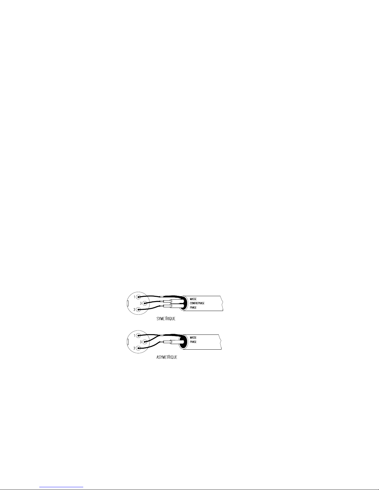
Le schéma suivant montre le branchement des sources audio symétriques ou asymétriques.
Quelques options du MPA4-80 et les positions des commutateurs correspondants sont
décrites plus loin dans le paragraphe 6.2. Pour le MPA6-80 dans le paragraphe 6.3.
Selon l’option choisie, les indicateurs SP s’allumeront seulement pour les canaux actifs.
Page 22

22
3.6. Branchement de sortie
La partie OUTPUT du panneau arrière du MPA4-80 est équipée de 8 borniers dévissables
(23, 24, 25, 26), 2 par amplificateur.
Les contrôles d’atténuation et les branchements de sortie sont décrits plus loin dans le
paragraphe 6.4.
La partie OUTPUT du panneau arrière du MPA6-80 est équipée de 12 borniers
dévissables (21, 22, 23, 24, 25, 26), 2 par amplificateur.
Les contrôles d’atténuation et les branchements de sortie sont décrits plus loin dans le
paragraphe 6.5.
Le câble de raccordement de l'amplificateur sur les enceintes doit être de bonne qualité
et de section suffisante surtout s'il existe une distance importante entre les amplificateurs et les
haut-parleurs. Il est recommandé d'utiliser du câble d'une section minimum de 2.5mm2 pour des
distances allant jusqu'à 10m et de 4mm2 pour les distances supérieures.
Souvenez-vous que la charge d’impédance minimum pour des amplificateurs mono ou
stéréo est de 4Ω. En mode bridgé, l’impédance doit être de 8Ω. Pour un bon fonctionnement de
l’appareil, vous devrez toujours respecter ces impédances.
Attention: en mode bridgé, utilisez uniquement les borniers rouges.
4. MISE EN MARCHE ET UTILISATION, FONCTIONNEMENT
4.1. Mise en marche
Appuyer sur l’interrupteur POWER (19), le voyant vert s’allume. Nous vous
recommandons vivement de suivre la séquence suivante : allumer tout d’abord les sources de son,
puis, la console de mixage, les égaliseurs, les filtres actifs et enfin les amplificateurs. Pour éteindre
procéder de la façon inverse. De cette façon, vos appareils s’abîmeront moins.
4.2. Atténuateurs d'entrée
Ils se présentent sous la forme d'un potentiomètre rotatif situés sur le panneau de
commandes (1, 4, 7, 10 pour le MPA4-80 et 1, 4, 7, 10, 13, 16 pour le MPA6-80).
Ces atténuateurs permettent de connecter différentes consoles de mixage, de régler le
volume de façon indépendante et de brancher des HP pouvant supporter une puissance inférieure
à celle administrée par l'amplificateur à plein rendement, sans aucun danger de les endommager
par une manipulation exagérée du volume de la console de mixage.
A l’intérieur du carton, contenant votre appareil, vous trouverez aussi un sachet
contenant 4/6 protections transparentes. Elles ont pour but de protéger les réglages d’atténuation
d’entrée des manipulations indésirables. Ces protections sont transparentes pour que l’on puisse
visualiser le réglage effectué.
Une fois insérées, elles ne peuvent être enlevés q’avec l’aide d’un tournevis non fourni.
Page 23

23
4.3. Indicateurs
Les indicateurs de présence du signal “SP” (2, 5, 8, 11 pour le MPA4-80 et 2, 5, 8, 11,
14, 17 pour le MPA6-80) s’allument quand le niveau en entrée est supérieur à -40dBV environ.
Les indicateurs de CLIP (3, 6, 9, et 12 pour le MPA4-80 et 3, 6, 9, 12, 15, 18 pour le
MPA6-80), s'allument quand le signal de sortie commence à écrêter (-1,5dB avant l'écrêtage réel).
Ce système de CLIP tient compte des variations possibles de la tension d'alimentation donnant
toujours une indication réelle tandis que la tension électrique varie. Il est normal qu'en travaillant à
des niveaux élevés, les indicateurs de CLIP s'allument au rythme des fréquences des graves, qui
sont celles qui ont le plus fort potentiel énergétique. Il faut éviter que ces voyants s'allument de
manière permanente.
5. ENTRETIEN
Le panneau de commandes ne devra jamais être nettoyé avec une substance
dissolvante, abrasive ou dérivée du pétrole car cela pourrait entraîner la décomposition de la
peinture.
Il est conseillé de nettoyer l’amplificateur avec un chiffon humecté d’eau avec un peu de
savon liquide, ou bien avec une solution d’eau et d’alcool à quantité égale. Ne jamais utiliser
d’objets pointus ou abrasifs pour nettoyer le panneau de commandes.
Si un liquide venait à couler sur les potentiomètres, veuillez faire réparer le MPA par
notre Service Technique ECLER.
Page 24

24
BEDIENUNGSANLEITUNG MPA4-80 / MPA6-80
1.WICHTIGE VORBEMERKUNG 25
2. EINFÜHRUNG 25
3. INSTALLATION 26
3.1. Aufstellungsort und Montage 26
3.2. Anschluss an das Netz 27
3.3. Ground Link-Schalter 27
3.4. Multifunktion 27
3.5. Eingangsanschlüsse 28
3.6. Ausgangsanschlüsse 29
4. BEDIENUNG 29
4.1. Inbetriebnahme 29
4.2. Eingangs-Trimmer 29
4.3. Anzeigen 30
5. REINIGUNG 30
6. DIAGRAMME 31
6.1. Technische Daten 31
6.2. Eingangsmöglichkeiten MPA4-80 32
6.3. Eingangsmöglichkeiten MPA6-80 34
6.4. Ausgangsmöglichkeiten MPA4-80 36
6.5. Ausgangsmöglichkeiten MPA6-80 37
6.6. Funktionsliste 39
6.7. Funktionsdiagramm 40
6.8. Blockschaltbild 41
Alle Angaben sind ohne Gewähr. Messwerte können produktionsbedingten Schwankungen unterliegen.
ECLER S.A. nimmt sich das Recht heraus Veränderungen am Gerät vorzunehmen, die zur Verbesserung des
Produktes beitragen.
Page 25

25
1. WICHTIGE VORBEMERKUNG
Herzlichen Glückwunsch! Sie besitzen hiermit ein hochwertiges Gerät als Ergebnis
eines großen Entwicklungsaufwandes und sorgfältiger Fertigungsplanung. Wir bedanken uns für
Ihr Vertrauen, einen ECLER MPA4-80 / MPA6-80 gewählt zu haben.
Bitte lesen Sie alle Erläuterungen in dieser Bedienungsanleitung sorgfältig durch, bevor
Sie das Gerät anschließen, um eine optimale Funktionalität und Leistung sicherzustellen.
Eventuelle Reparaturen sollten nur von unserer technischen Service-Abteilung
vorgenommen werden, um einen zuverlässigen Betrieb sicherzustellen.
2. EINFÜHRUNG
Die Verstärkungsstation MPA4-80 besteht aus vier 77W/4Ω Verstärkern, die durch
Wahlschalter an der Rückseite des Geräts konfiguriert werden können. Dies ermöglicht
verschiedenste Arbeitsmöglichkeiten, wie zum Beispiel:
Vier Mono-Verstärker für vier verschiedene Mono-Signale.
Der MPA4-80 ist bereit, mit vier verschiedenen Signalen zu arbeiten. Dabei hat jedes eine
eigene Pegelregelung.
Vier Mono-Verstärker für ein gemeinsames Eingangssignal.
Der Verstärker arbeitet jetzt nur mit einem Eingangssignal, behält jedoch die Möglichkeit, die
Pegel der vier Kanäle unabhängig zu regeln. Diese Konfiguration ist besonders nützlich, wenn es
sich um die Verteilung eines Audiosignals an verschiedene Zonen handelt.
Vier Mono-Verstärker für einen gemeinsamen Stereo-Eingang.
Diese Anwendung gleicht der vorigen, der Eingang ist jedoch ein Stereo-Signal. Der Verstärker
addiert beide Eingangskanäle zu einem einzigen Mono-Signal.
Zwei Stereo-Verstärker für zwei verschiedene Stereo-Eingänge.
Jeder Stereo-Kanal verfügt über eine eigene Pegelregelung. Nützlich, um zwei Zonen mit zwei
verschiedenen Stereo-Signalen zu beschallen.
Zwei Stereo-Verstärker für einen gemeinsamen Stereo-Eingang.
Diese Anwendung gleicht der vorigen, der Eingang der beiden Verstärker ist jedoch das gleiche
Stereo-Signal.
Zwei Verstärker im Brückenbetrieb für zwei verschiedene Mono-Signale.
Diese konfiguration ergibt einen herkömmlichen Stereo-Verstärker. Mit einem überbrückten
Versärker erhalten Sie eine verdoppelte Ausgangsleistung mit einer midest- Lastimpedanz von
8Ω.
Zwei Verstärker im Brückenbetrieb für einen gemeinsamen Mono-Eingang
Der Verstärker arbeitet mit einem einzigem Mono-Signal für beide Verstärker, behält jedoch die
Möglichkeit, die Pegel der beiden Kanäle unabhängig zu regeln.
Zwei Verstärker im Brückenbetrieb für einen gemeinsamen Stereo-Eingang
Diese Anwendung gleicht der vorigen, der Eingang ist aber jetzt ein Stereo-Signal. Der
Verstärker addiert beide Kanäle und verwandelt sie in ein Mono-Signal.
Zwei Mono-Verstärker und ein Verstärker im Brückenbetrieb für einen gemeinsamen
Mono-Eingang.
Nützlich in Anlagen mit zwei Verstärkern für Mitten- und Höhenboxen. Der dritte (überbrückte)
Verstärker dient für einen Subwoofer. (Dieser Verstärker verfügt über keine Art Filter)
Page 26

26
Die MPA6-80 Verstärkerstation hingegen, besteht aus sechs 75W/4Ω Verstärkern, die
durch Wahlschalter an der Rückseite des Geräts konfiguriert weden können. Dies ermöglicht
verschiedenste Arbeitsmöglichkeiten, wie zum Beispiel:
Sechs Mono-Verstärker für sechs verschiedene Mono-Signale.
Der MPA6-80 ist bereit, mit sechs verschiedenen Signalen zu arbeiten. Dabei hat jedes eine
eigene Pegelregelung.
Sechs Mono-Verstärker für ein gemeinsames Eingangssignal.
Der Verstärker arbeitet jetzt nur mit einem Eingangssignal, behält jedoch die Möglichkeit, die
Pegel der sechs Kanäle unabhängig zu regeln. Diese Konfiguration ist besonders nützlich, wenn
es sich um die Verteilung eines Audiosignals an verschiedene Zonen handelt.
Sechs Mono-Verstärker für einen gemeinsamen Stereo-Eingang.
Diese Anwendung gleicht der vorigen, der Eingang ist jedoch ein Stereo-Signal. Der Verstärker
addiert beide Eingangskanäle zu einem einzigen Mono-Signal.
Drei Stereo-Verstärker für zwei verschiedene Stereo-Eingänge.
Jeder Stereo-Kanal verfügt über eine eigene Pegelregelung. Nützlich, um zwei Zonen mit zwei
verschiedenen Stereo-Signalen zu beschallen.
Drei Stereo-Verstärker für einen gemeinsamen Stereo-Eingang.
Diese Anwendung gleicht der vorigen, der Eingang der beiden Verstärker ist jedoch das gleiche
Stereo-Signal.
Drei Verstärker im Brückenbetrieb für drei verschiedene Mono-Signale.
Diese konfiguration ergibt einen herkömmlichen Stereo-Verstärker. Mit einem überbrückten
Verstärker erhalten Sie eine verdoppelte Ausgangsleistung mit einer midest- Lastimpedanz von
8Ω.
Drei Verstärker im Brückenbetrieb für einen gemeinsamen Mono-Eingang
Der MPA6-80 ist bereit, mit einem einzigen Mono-Signal für alle drei Verstärker zu arbeiten.
Dabei hat jeder Kanal eine eigene Pegelregelung.
Drei Verstärker im Brückenbetrieb für einen gemeinsamen Stereo-Eingang
Diese Anwendung gleicht der vorigen, der Eingang ist aber jetzt ein Stereo-Signal. Der
Verstärker addiert beide Kanäle und verwandelt sie in ein Mono-Signal.
Vier Mono-Verstärker und ein Verstärker im Brückenbetrieb für einen gemeinsamen
Mono-Eingang. Nützlich in Anlagen mit zwei Verstärkern für Mitten- und Höhenboxen. Der dritte
(überbrückte) Verstärker dient für einen Subwoofer. (Dieser Verstärker verfügt über keine Art
Filter)
3. INSTALLATION
3.1. Aufstellungsort und Montage
Der Verstärker ist im 19'' Rackformat konzipiert und ist zwei HE hoch. Es werden für
den Einbau in ein Rack Plastikringe mitgeliefert, um das Gerät nicht zu beschädigen.
Wegen der Hitze-erzeugenden Natur des Verstärkers ist es nicht empfehlenswert, das
Gerät in extremen Temperaturen zu betreiben.
Es sollte mit genügend Abstand zu anderen Geräten in das Rack eingebaut werden.
Page 27

27
3.2. Anschluss an das Netz
Der Verstärker kann mit Wechselstrom von 110-120, 220-240 V, 50/60Hz betrieben
werden, (siehe Aufkleber auf dem Gerät). Der Stromverbrauch bei Höchstleistung beträgt im
Fall des MPA4-80 370 VA und beim MPA6-80 520VA. Vergewissern sie sich, daß Ihr
Verstärker den Stromverhältinissen Ihres Landes entspricht.
Es sollte ein angemessener Erdungsanschluss vorhanden sein (Erdungswiederstand
maximal 30Ω)
Die Betriebsatmosphäre sollte trocken und vollkommen Staubfrei sein.
Jeder Anschluss oder sonstige Manipulation sollte mit ausgeschaltetem Gerät
vorgenommen werden.
Es sollte verhindert werden, das Netzkabel mit den geschirmten, signalführenden
Kablen zu verdrehen, da dies zu Störgeräuschen führen kann.
Um den Verstärker vor eventuellen Stromschwankungen oder momentanen
Leistungsspitzen der internen Schaltungen zu schützen, verwendet der MPA4-80 eine
T4A Sicherung und der MPA6-80 eine T6.3A Sicherung (34). Sollte sie durchbrennen,
muß das Gerät von der Stromversorgung getrennt und die Sicherung gegen eine neue mit
identischen Werten ausgetauscht werden. Falls auch diese durchbrennt, wenden Sie sich bitte
an unsere technische Service Abteilung. NIEMALS DARF EINE SICHERUNG MIT HÖHEREM
WERT EINGESETZT WERDEN.
3.3. Grund Link-Schalter
Der Ground Link-Schalter (35) hat als Aufgabe, Erdungsschleifen zu verhindern, wenn
verschiedene Geräte im selben System gleichzeitig an Masse angeschlossen sind. Dieser
Schalter ermöglicht das Abschalten der elektischen Masse von der Masse des Gehäuses. Im Fall
von Störgeräuschen benutzen Sie entweder diesen oder den entsprechenden Schalter an den
angeschlossenen Geräten.
3.4. Multifunktion
Bei dem MPA4-80 verfügen Sie über vier verschiedene Verstärkungskonfigurationen,
je nachdem wie die Eingangswahlschalter an der Rückseite des Geräts (39, 40, 41, 42, 43, 44)
eingestellt sind.
- Vier Mono-Verstärker mit folgenden Möglichkeiten
Vier verschiedene Mono-Eingänge
Ein gemeinsamer Mono-Eingang für alle Verstärker
Ein gemeinsamer Stereo-Eingang für alle Verstärker
- Zwei Stereo-Verstärker mit folgenden Möglichkeiten:
Zwei verschiedene Stereo-Eingänge
Ein einziger Stereo-Eingang für beide Verstärker
- Zwei Verstärker im Brückenbetrieb mit folgenden Möglichkeiten:
Zwei verschiedene Mono-Eingänge
Ein gemeinsamer Mono-Eingang
Ein gemeinsamer Stereo-Eingang
- Kombinationen zwischen Mono- Stereo- und überbrückten Verstärkern
Page 28
28
Bei dem MPA6-80 verfügen Sie über vier verschiedene Verstärkungskonfigurationen,
je nachdem wie die Eingangswahlschalter an der Rückseite des Geräts (36, 37, 38, 39, 40, 41,
42, 43, 44) eingestellt sind.
- Sechs Mono-Verstärker mit folgenden Möglichkeiten
Sechs verschiedene Mono-Eingänge
Ein gemeinsamer Mono-Eingang für alle Verstärker
Ein gemeinsamer Stereo-Eingang für alle Verstärker
- Drei Stereo-Verstärker mit folgenden Möglichkeiten:
Drei verschiedene Stereo-Eingänge
Ein einziger Stereo-Eingang für alle drei Verstärker
- Drei Verstärker im Brückenbetrieb mit folgenden Möglichkeiten:
Drei verschiedene Mono-Eingänge
Ein gemeinsamer Mono-Eingang
Ein gemeinsamer Stereo-Eingang
- Kombinationen zwischen Mono- Stereo- und überbrückten Verstärkern
3.5 Eingangsanschlüsse
Die Eingangsbuchsen des MPA4-80 (29, 30, 31, 32) und des MPA6-80
(27, 28, 29, 30, 31, 32) sind elektronisch symmetrierte XLR-Buchsen mit einer
Eingangsimpedanz von >20kΩ und einer Nennempfindlichkeit von 0dBV(1V) Die Pinbesetzung
ist:
1. GROUND (Masse)
2. PHASE (Phasengleich bezüglich Ausgang)
3. NON PHASE (Phasenverkehrt bezüglich Ausgang)
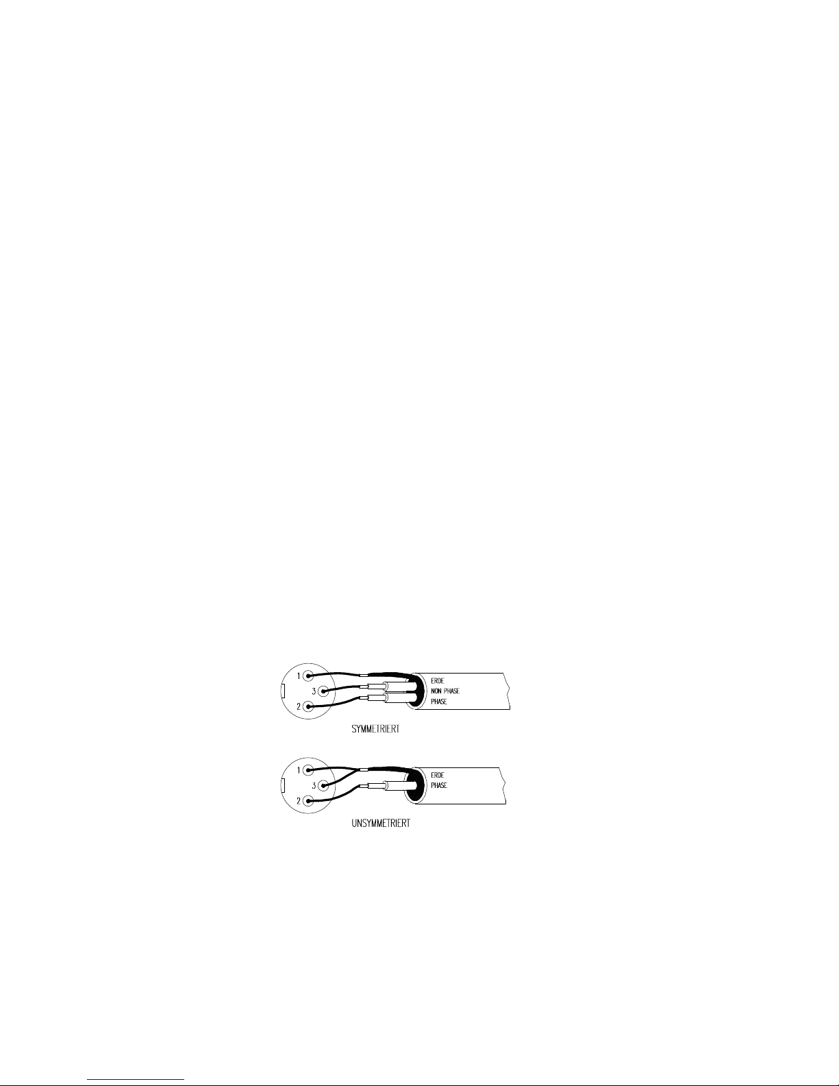
Folgende Abbildung zeigt den Anschluss der Eingänge bei symmetrierten oder nicht
symmetrierten Audioquellen:
Einige der Anschlussmöglichkeiten des MPA4-80 und die zugehörigen Wahlschalter-Positionen
werden im Paragraph 6.2. beschrieben (MPA6-80: Paragraph 6.3.)
Je nachdem, welche Konfiguration Sie benutzen, leuchten nur die SPAnzeigen der aktiven
Kanäle.
Page 29

29
3.6 Ausgangsanschlüsse
Im OUTPUT-Bereich auf der Rückseite des MPA4-80 befinden sich 8 Schraubklemmen
(23, 24, 25, 26), ein Paar pro Verstärker. Die Verschiedenen Ausgangskonfigurationen werden
in Paragraph 6.4. beschrieben.
Im OUTPUT-Bereich auf der Rückseite des MPA6-80 befinden sich 12
Schraubklemmen (21, 22, 23, 24, 25, 26), ein Paar pro Verstärker. Die Verschiedenen
Ausgangskonfigurationen werden in Paragraph 6.5. beschrieben.
Das Kabel, welches den Verstärker mit den Lautsprechern verbindet, sollte hochwerig
und so kurz und stark wie möglich sein. Dies hat eine grössere Bedeutung wenn lange Strecken
zu verkabelten sind. Für bis zu 10m empfehlen wir Kabel der Stärke 2.5mm², für längere
Strecken 4mm².
Beachten Sie, daß die Lastimpedanz an den Verstärkern (Mono oder Stereo)
mindestens 4Ω beträgt. Im Brückenbetrieb muss die Lastimpedanz mindestens 8Ω betragen.
Um einen sicheren Betrieb der Verstärker zu gewährleisten, schliessen Sie in keinem Fall
niedrigere Impedanzen an.
Achtung: Benutzen sie im Brückenbetrieb nur die roten Schraubklemmen.
4. BEDIENUNG
4.1. Inbetriebnahme
Dieses Gerät wird durch den Netzschalter POWER (19) eingeschaltet, wobei eine
integrierte Kontroll-Leuchte den Betriebszustand anzeigt.Es ist höchst zu empfehlen, Geräte in
folgender, "sicherer'' Reihenfolge einzuschalten: Zuerst die Signalquellen, dann Mischpult,
Equalizer, aktive Fliter und schließlich die Endstufen (Verstärker). Um die Geräte auszuschalten,
verfahren Sie in umgekehrter Reihenfolge. Wenn Sie dies beachten, werden die beim
Einschalten erzeugten Spannungsspitzen keines der angeschlossenen Geräte in irgendeiner
Weise beeinträchtigen und daher auch nicht die besonders empfindlichen Lautsprecher
erreichen, die dadurch beschädigt werden könnten.
4.2. Eingangs-Trimmer
Es handelt sich um drehbare Potentiometer, welche an der Vorderseite des Gerätes
angebracht sind. (1, 4, 7, 10 beim MPA4-80 und 1, 4, 7, 10, 13, 16 beim MPA6-80)
Diese Trimmer ermöglichen den Anschluss verschiedener Mischpulte oder
Vorverstärker, unabhängige Volume-Regelug pro Kanal und den Anschluss von Lautsprechern,
die die Höchstleistung des Verstärkers nicht bestehen würden. Damit wird die Gefahr, die
Lautsprecher durch eine Fehlmanipulation am Mischpult oder Vorverstärker zu beschädigen
beseitigt.
Im Inneren der Gerätverpackung finden Sie eine kleine Plastiktüte mit 4/6
transparenten Deckeln, die dazu dienen, unerwünschte Manipulationen der EingangspegelRegler zu verhindern. Diese Deckel sind transparent, um den aktuellen Zustand der
Einstellungen visualisieren zu können.
Wenn Sie die Deckel gesteckt haben, können sie nicht mehr mit bloßen Fingern entfernt
werden, dazu benötigen Sie jediglich einen kleinen Schraubendreher.
Page 30

30
4.3. Anzeigen
Die SP-Anzeigen (Signal Present) weisen auf Anwesenheit eines Audiosignals am
Eingang des Verstärkers hin (2, 5, 8, 11 beim MPA4-80 und 2, 5, 8, 11, 14, 17 beim
MPA6-80). Diese Kontroll-LEDs leuchten auf, wenn das Eingangssignal ca. 40dBV erreicht oder
überschreitet.
Die CLIP-Anzeigen (3, 6, 9 und 12 beim MPA4-80 und 3, 6, 9, 12, 15, 18 beim
MPA6-80) leuchten auf, wenn das Ausgangssignal für die Lautsprecher 1.5dB unter der
eigentlichen Clip-Grenze liegt. Dieses Clip-System betrachtet die eventuellen
Spannungsschwankungen, gibt also immer eine gültige Anzeige. Es ist normal, das im Betrieb
bei voller Leistung die CLIP-Anzeige im Rhythmus der Tieffrequenzen aufleuchtet, da diese die
größte Energie besitzen. Es sollte nur beachtet werden, daß die CLIP-Anzeigen nicht permanent
leuchten.
5 REINIGUNG
Die Frontplatte darf weder mit scheuernden Substanzen noch mit
lösungsmittelhaltigen Reinigern behandelt werden, da sonst die Oberfläche beschädigt würde.
Um das Gerät zu reinigen verwenden Sie ein angefeuchtetes Tuch mit schwacher Seifenlösung
oder ein Gemisch aus Wasser und Alkohol zu gleichen Teilen. Bitte achten Sie darauf, daß keine
Flüssigkeiten ins Innere des Geräts gelangen können. Verwenden Sie niemals spitze oder
scharfe Gegen-stände. Sollte Flüssigkeit ins Gerät gedrungen sein, verwenden Sie keine Sprays
und benachrichtigen Sie umgehend die nächste ECLER Service Abteilung.
Page 31

31
6. DIAGRAMS 6. DIAGRAMAS
6. SCHÉMAS 6. DIAGRAMME
6.1. Technical characteristics 6.1. Características técnicas
6.1. Caractéristiques techniques 6.1. Technische Daten
MPA4-80 MPA6-80
POWER 20-20kHz 1% THD
1 Channel @ 4Ω 77 WRMS 75 WRMS
1 Channel @ 8Ω 48 WRMS 48 WRMS
All Channels @ 4Ω 52 WRMS 56 WRMS
All Channels @ 8Ω 39 WRMS 40 WRMS
1 Bridged channel @ 8Ω (all channels driven) 104 WRMS 112 WRMS
Frequency response (-1dB) 20Hz - 90kHz 20Hz - 90kHz
THD+Noise @ 1kHz Full Pwr. <0.01% <0.01%
Intermodulation distortion 50Hz & 7kHz, 4:1 <0.02% <0.02%
TIM 100 <0.05% <0.05%
S+N/N 20Hz -20kHz @ 1W/4Ω >90dB >90dB
Damping factor 1kHz @ 8Ω >160 >160
Slew Rate ±10V/µs ±10V/µs
Channel crosstalk >60dB >60dB
Input connector XLR3 balanced XLR3 balanced
Input Sensitivity / Impedance 0dB / >20kΩ 0dB / >20kΩ
Signal Present indicator -40dBV -40dBV
Output connector Screw terminal Screw terminal
Clip indicators -1.5dB real clip -1.5dB real clip
Mains Depending on your country See characteristics in the back of the unit.
Power consumption (max. Out) 370VA 520VA
Dimensions Panel 482.6x88
Depth 342.5
Weight 9.3kg 11.2kg
Page 32

32
6.2. MPA4-80 input options 6.2. Opciones de entrada MPA4-80
- Option 1. (mono) 4 mono amplifiers for four
different mono signal
- Opción 1. (mono) 4 amplificadores en mono para
cuatro señales mono diferentes
- Option 2. (mono) 4 mono amplifiers for a common
mono input
- Opción 2. (mono) 4 amplificadores en mono con
una entrada en común
- Option 3. (mono) 4 mono amplifiers for a common
stereo input
- Opción 3. (mono) 4 amplificadores en mono con
una entrada estéreo en común
- Option 4. (stereo) 2 stereo amplifiers for two
different stereo inputs
- Opción 4. (estéreo) 2 amplificadores estéreo con
dos entradas estéreo diferentes
- Option 5. (stereo) 2 stereo amplifiers for a common
stereo input
- Opción 5.(estéreo) 2 amplificadores estéreo con
entrada estéreo común
- Option 6. (bridged) 2 bridged amplifiers for two
different mono signals
- Opción 6. (puente) 2 amplificadores en puente con
dos señales mono diferentes
- Option 7. (bridged) 2 bridged amplifiers for a
common mono signal
- Opción 7. (puente) 2 amplificadores en puente con
una señal mono en común
- Option 8. (bridged) 2 bridged amplifiers for a
common stereo signal
- Opción 8. (puente) 2 amplificadores en puente con
una entrada estéreo común
- Option 9. (combination) 1 bridged amplifier and 2
mono amplifiers for a common mono input
- Opción 9. (combinado) 1 amplificador en puente y 2
amplificadores mono con una entrada mono común
- Option 10. (combination) 1 bridged amplifier and 1
stereo amplifier for two different stereo inputs
- Opción 10. (combinado) 1 amplificador en puente y
1 amplificador estéreo con dos entradas estéreo
diferentes
6.2. Options d’entrée MPA4-80
6.2. Eingangsmöglichkeiten MPA4-80
- Option 1. (mono) 4 amplificateurs mono pour 4
signaux mono différents
- Option 1. (mono) 4 Mono-Verstärker für vier
verschiedene Mono-Signale
- Option 2. (mono) 4 amplificateurs mono pour 1
entrée mono commune
- Option 2. (mono) 4 Mono-Verstärker für ein
gemeisames Mono-Signal
- Option 3. (mono) 4 amplificateurs mono pour 1
entrée stéréo commune
- Option 3. (mono) 4 Mono-Verstärker für ein
gemeisames Stereo-Signal
- Option 4. (stéréo) 2 amplificateurs stéréo pour 2
entrées stéréo différentes
- Option 4. (stereo) 2 Stereo-Verstärker für zwei
verschiedene Stereo-Signale
- Option 5. (stéréo) 2 amplificateurs stéréo pour 1
entrée stéréo commune
- Option 5. (stereo) 2 Stereo-Verstärker für ein
gemeisames Stereo-Signal
- Option 6. (bridgé) 2 amplificateurs bridgés pour 2
signaux mono différents
- Option 6. (überbrückt) 2 Verstärker im
Brückenbetrieb für zwei verschiedene Mono-Signale
- Option 7. (bridgé) 2 amplificateurs bridgés pour 1
signal mono commun
- Option 7. (überbrückt) 2 Verstärker im
Brückenbetrieb für ein gemeisames Mono-Signal
- Option 8. (bridgé) 2 amplificateurs bridgés pour 1
signal stéréo commun
- Option 8. (überbrückt) 2 Verstärker im
Brückenbetrieb für ein gemeisames Stereo-Signal
- Option 9. (combinaison) 1 amplificateur bridgé et 2
amplificateurs mono pour 1 entrée mono commune
- Option 9. (Kombination) 1Verstärker im
Brückenbetrieb und 2 Mono-Verstärker für ein
gemeisames Mono-Signal
- Option 10. (combinaison) 1 amplificateur bridgé et un
amplificateur stéréo pour 2 entrées stéréo différentes
- Option 10. (Kombination) 1 Verstärker im
Brückenbetrieb und 1 Stereo-Verstärker für zwei
verschiedene Stereo-Signale
Page 33
33
INPUTS INPUTS SELECTORS MODE ST-BR
N.
1 2 3 4 CH1 CH2 CH3 CH4 CH1-2 CH3-4
1 I1 I2 I3 I4 IN1 IN2 IN3 IN4 ST ST
2 I - - - IN1 LINK CH1 LINK CH1 LINK CH2 ST ST
3 L R - - IN1+IN2 LINK CH1 LINK CH1 LINK CH2 ST ST
4 L1 R1 L2 R2
IN1 IN2 IN3 IN4 ST ST
5 L R - - IN1 IN2 LINK CH1 LINK CH2 ST ST
6 L - R - IN1 - IN3 - BR BR
7 I - - - IN1 - LINK CH1 - BR BR
8 L R - - IN1+IN2 - LINK CH1 - BR BR
9 I - - - IN1 LINK CH1 LINK CH1 LINK CH2 BR ST
10 L1 R1 L2 R2 IN1+IN2 - IN3 IN4 BR ST
Page 34

34
6.3. MPA6-80 input options 6.3. Opciones de entrada MPA6-80
- Option 1. (mono) 6 mono amplifiers for six different
mono signal
- Opción 1. (mono) 6 amplificadores en mono para seis
entradas mono diferentes
- Option 2. (mono) 6 mono amplifiers for a common
mono input
- Opción 2. (mono) 6 amplificadores en mono con una
entrada común
- Option 3. (mono) 6 mono amplifiers for a common
stereo input
- Opción 3. (mono) 6 amplificadores en mono con una
entrada estéreo común
- Option 4. (stereo) 3 stereo amplifiers for three
different stereo inputs
- Opción 4. (estéreo) 3 amplificadores estéreo con tres
entradas estéreo diferentes
- Option 5. (stereo) 3 stereo amplifiers for a common
stereo input
- Opción 5. (estéreo) 3 amplificadores estéreo con
entrada estéreo común
- Option 6. (bridged) 3 bridged amplifiers for three
different mono signals
- Opción 6. (puente) 3 amplificadores en puente con
tres entradas mono diferentes
- Option 7. (bridged) 3 bridged amplifiers for a common
mono signal
- Opción 7. (puente) 3 amplificadores en puente con
una entrada mono en común
- Option 8. (bridged) 3 bridged amplifiers for a common
stereo signal
- Opción 8. (puente) 3 amplificadores en puente con
una entrada estéreo en común
- Option 9. (combination) 1 bridged amplifier and 4
mono amplifiers for a common mono input
- Opción 9. (combinado) 1 amplificador en puente y 4
amplificadores mono con una entrada mono común
- Option 10. (combination) 1 bridged amplifier and 2
stereo amplifier for three different stereo inputs
- Opción 10. (combinado) 1 amplificador en puente y 2
amplificadores estéreo con tres entradas estéreo
diferentes
- Option 11. (combination) 2 bridged amplifiers and 2
mono amplifiers for a common mono input
- Opción 11. (combinado) 2 amplificadores en puente y
2 amplificadores en mono con una entrada mono en
común
6.3. Options d’entrée MPA6-80 6.3. Eingangsmöglichkeiten MPA6-80
- Option 1. (mono) 6 amplificateurs mono pour 6
signaux mono différents
- Option 1. (mono) 6 Mono-Verstärker für sechs
verschiedene Mono-Signale
- Option 2. (mono) 6 amplificateurs mono pour 1
entrée mono commune
- Option 2. (mono) 6 Mono-Verstärker für ein
gemeisames Mono-Signal
- Option 3. (mono) 6 amplificateurs mono pour 1
entrée stéréo commune
- Option 3. (mono) 6 Mono-Verstärker für ein
gemeisames Stereo-Signal
- Option 4. (stéréo) 3 amplificateurs stéréo pour 3
entrées stéréo différentes
- Option 4. (stereo) 3 Stereo-Verstärker für drei
verschiedene Stereo-Signale
- Option 5. (stéréo) 3 amplificateurs stéréo pour 1
entrée stéréo commune
- Option 5. (stereo) 3 Stereo-Verstärker für ein
gemeisames Stereo-Signal
- Option 6. (bridgé) 3 amplificateurs bridgés pour 3
signaux mono différents
- Option 6. (überbrückt) 3 Verstärker im Brückenbetrieb
für drei verschiedene Mono-Signale
- Option 7. (bridgé) 3 amplificateurs bridgés pour 1
signal mono commun
- Option 7. (überbrückt) 3 Verstärker im Brückenbetrieb
für ein gemeisames Mono-Signal
- Option 8. (bridgé) 3 amplificateurs bridgés pour 1
signal stéréo commun
- Option 8. (überbrückt) 3 Verstärker im Brückenbetrieb
für ein gemeisames Stereo-Signal
- Option 9. (combinaison) 1 amplificateur bridgé et 4
amplificateurs mono pour 1 entrée mono commune
- Option 9. (Kombination) 1Verstärker im
Brückenbetrieb und 4 Mono-Verstärker für ein
gemeisames Mono-Signal
- Option 10. (combinaison) 1 amplificateur bridgé et 2
amplificateurs stéréo pour 3 entrées stéréo différentes
- Option 10. (Kombination) 1 Verstärker im
Brückenbetrieb und 2 Stereo-Verstärker für drei
verschiedene Stereo-Signale
- Option 11. (combinaison) 2 amplificateurs bridgés et
2 amplificateurs mono pour 1 entrée mono commune
- Option 11. (Kombination) 2 Verstärker im
Brückenbetrieb und 2 Mono-Verstärker für ein
gemeisames Mono-Signal
Page 35

35
INPUTS INPUTS SELECTORS MODE ST-BR
N.
1 2 3 4 5 6 CH1 CH2 CH3 CH4 CH5 CH6 CH1-2 CH3-4 CH5-6
1 I1 I2 I3 I4 I5 I6 IN1 IN2 IN3 IN4 IN5 IN6 ST ST ST
2 I - - - - - IN1
LINK
CH1
LINK
CH1
LINK
CH2
LINK
CH3
LINK
CH4
ST ST ST
3 L R - - - - IN1+IN2
LINK
CH1
LINK
CH1
LINK
CH2
LINK
CH3
LINK
CH4
ST ST ST
4 L1 R1 L2 R2 L3 R3 IN1 IN2 IN3 IN4 IN5 IN6 ST ST ST
5 L R - - - - IN1 IN2
LINK
CH1
LINK
CH2
LINK
CH3
LINK
CH4
ST ST ST
6 I1 - I2 - I3 - IN1 - IN3 - IN5 - BR BR BR
7 I - - - - - IN1 -
LINK
CH1
-
LINK
CH3
- BR BR BR
8 L R - - - - IN1+IN2
-
LINK
CH1
-
LINK
CH3
- BR BR BR
9 I - - - - - IN1
LINK
CH1
LINK
CH1
LINK
CH2
LINK
CH3
LINK
CH4
BR ST ST
10 L1 R1 L2 R2 L3 R3 IN1+IN2
- IN3 IN4 IN5 IN6 BR ST ST
11 I - - - - - IN1
LINK
CH1
LINK
CH1
LINK
CH2
LINK
CH3
LINK
CH4
BR BR ST
Page 36

36
6.4. MPA4-80 output options 6.4. Opciones de salida MPA4-80
- Option 1. 4 mono amplifiers - Opción 1. 4 Amplificadores en mono
- Option 2. 2 stereo amplifiers - Opción 2. 2 Amplificadores en estéreo
- Option 3. 2 bridged amplifiers - Opción 3. 2 Amplificadores en puente
- Option 4. 1 bridged amplifier and 2 mono amplifiers
for a common mono input
- Opción 4. 1 Amplificador en puente y 2
amplificadores mono con una entrada mono común
- Option 5. 1 bridged amplifier and 1 stereo amplifier
for two different stereo amplifiers
- Opción 5. 1 Amplificador en puente y 1
amplificador estéreo con dos entradas estéreo
diferentes
6.4. Options de sortie MPA4-80 6.4. Ausgangsmöglichkeiten MPA4-80
- Option 1. 4 amplificateurs mono
- Option 1. 4 Mono-Verstärker
- Option 2. 2 amplificateurs stéréo
- Option 2. 2 Stereo-Verstärker
- Option 3. 2 amplificateurs bridgés
- Option 3. 2 Verstärker im Brückenbetrieb
- Option 4. 1 amplificateur bridgé et 2 amplificateurs
mono pour 1 entrée mono commune
- Option 4. 1 Verstärker im Brückenbetrieb und 2
Mono-Verstärker für ein gemeinsames Mono-Signal
- Option 5. 1 amplificateur bridgé et 1 amplificateur
stéréo pour 2 entrées stéréo différentes
- Option 5. 1 Verstärker im Brückenbetrieb und 1
Stereo-Verstärker für zwei verschiedene StereoSignale
N. ACTIVE VOL CH 1 CH 2 CH 3 CH 4
1 CH1,2,3,4 + - + - + - + 2 CH1,2,3,4 + - + - + - + 3 CH1,3 + BRIDGED - + BRIDGED 4 CH1,3,4 + BRIDGED - + - + 5 CH1,3,4 + BRIDGED - + - + -
Page 37

37
6.5. MPA6-80 output options 6.5. Opciones de salida MPA6-80
- Option 1. 6 mono amplifiers - Opción 1. 6 Amplificadores en mono
- Option 2. 3 stereo amplifiers - Opción 2. 3 Amplificadores estéreo
- Option 3. 3 bridged amplifiers - Opción 3. 3 Amplificadores en puente
- Option 4. 1 bridged amplifier and 4 mono amplifiers
for a common mono input
- Opción 4. 1 Amplificador en puente y 4
amplificadores mono con una entrada mono común
- Option 5. 1 bridged amplifier and 2 stereo amplifiers
for three different stereo amplifiers
- Opción 5. 1 Amplificador en puente y 2
amplificadores estéreo con tres entradas en estéreo
diferentes
- Option 6. 2 bridged amplifiers and 2 mono
amplifiers for a common mono input
- Opción 6. 2 Amplificadores en puente y 2
amplificadores en mono con una entrada mono
común
6.5. Options de sortie MPA6-80 6.5. Ausgangsmöglichkeiten MPA6-80
- Option 1. 6 amplificateurs mono
- Option 1. 6 Mono-Verstärker
- Option 2. 3 amplificateurs stéréo
- Option 2. 3 Stereo-Verstärker
- Option 3. 3 amplificateurs bridgés
- Option 3. 3 Verstärker im Brückenbetrieb
- Option 4. 1 amplificateur bridgé et 4 amplificateurs
mono pour une 1 entrée mono commune
- Option 4. 1 Verstärker im Brückenbetrieb und 4
Mono-Verstärker für ein gemeinsames Mono-Signal
- Option 5. 1 amplificateur bridgé et 2 amplificateurs
stéréo pour 3 entrées stéréo différentes
- Option 5. 1 Verstärker im Brückenbetrieb und 2
Stereo-Verstärker für drei verschiedene StereoSignale
- Option 6. 2 amplificateurs bridgés et 2 amplificateurs
mono pour 1 entrée mono commune
- Option 6. 2 Verstärker im Brückenbetrieb und 2
Mono-Verstärker für ein gemeinsames Mono-Signal
N. VOL ACTIVO CH 1 CH 2 CH 3 CH 4 CH 5 CH 6
1 CH1,2,3,4,5,6 + - + - + - + - + - + 2 CH1,2,3,4,5,6 + - + - + - + - + - + 3 CH1,3,5 + BRIDGED - + BRIDGED - + BRIDGED 4 CH1,3,4,5,6 + BRIDGED - + - + - + - + 5 CH1,3,4,5,6 + BRIDGED - + - + - + - + 6 CH1,3,5,6 + BRIDGED - + BRIDGED - + - + -
Page 38

38
6.6. Function list 6.6. Lista de funciones
1. Channel 1 volume, VOL
1. Volumen canal 1, VOL
2. Input 1 Signal presence, SP
2. Indicador de presencia de señal en entrada 1, SP
3. Channel 1 Clip indication, CLIP
3. Indicador de recorte canal 1, CLIP
4. Channel 2 volume, VOL
4. Volumen canal 2, VOL
5. Input 2 Signal presence, SP
5. Indicador de presencia de señal en entrada 2, SP
6. Channel 2 Clip indication, CLIP
6. Indicador de recorte canal 2, CLIP
7. Channel 3 volume, VOL
7. Volumen canal 3, VOL
8. Input 3 Signal presence, SP
8. Indicador de presencia de señal en entrada 3, SP
9. Channel 3 Clip indication, CLIP
9. Indicador de recorte canal 3, CLIP
10. Channel 4 volume, VOL
10. Volumen canal 4, VOL
11. Input 4 Signal presence, SP
11. Indicador de presencia de señal en entrada 4, SP
12. Channel 4 Clip indication, CLIP
12. Indicador de recorte canal 4, CLIP
13. Channel 5 volume, VOL
13. Volumen canal 5, VOL
14. Input 5 Signal presence, SP
14. Indicador de presencia de señal en entrada 5, SP
15. Channel 5 Clip indication, CLIP
15. Indicador de recorte canal 5, CLIP
16. Channel 6 volume, VOL
16. Volumen canal 6, VOL
17. Input 6 Signal presence, SP
17. Indicador de presencia de señal en entrada 6, SP
18. Channel 6 Clip indication, CLIP
18. Indicador de recorte canal 6, CLIP
19. Power switch and pilot light, POWER
19. Interruptor y piloto de puesta en marcha, POWER
20. Mains socket
20. Base de red
21. Output terminals channel 6, CH6
21. Terminales atornillables salida 6, CH 6
22. Output terminals channel 5, CH5
22. Terminales atornillables salida 5, CH 5
23. Output terminals channel 4, CH4
23. Terminales atornillables salida 4, CH 4
24. Output terminals channel 3, CH3
24. Terminales atornillables salida 3, CH 3
25. Output terminals channel 2, CH2
25. Terminales atornillables salida 2, CH 2
26. Output terminals channel 1, CH1
26. Terminales atornillables salida 1, CH 1
27. XLR input connector 6, IN6
27. Conector XLR entrada 6, IN6
28. XLR input connector 5, IN5
28. Conector XLR entrada 5, IN5
29. XLR input connector 4, IN4
29. Conector XLR entrada 4, IN4
30. XLR input connector 3, IN3
30. Conector XLR entrada 3, IN3
31. XLR input connector 2, IN2
31. Conector XLR entrada 2, IN2
32. XLR input connector 1, IN1
32. Conector XLR entrada 1, IN1
33. Ground terminal, GND
33. Terminal de masa, GND
34. Fuse holder
34. Portafusible
35. Electrical ground / mechanical ground
35. Conmutador de desconexión masa eléctrica/masa
disconnection switch, GND LINK
mecánica, GND LINK
36. Stereo / bridge channel 5/6 switch, ST/BRIDGE
36. Conmutador stereo bridge canal 5/6, ST/BRIDGE
37. Channel 6 / link channel 4 switch, IN6/LINK CH4 37. Conmutador canal 6 / link canal 4, IN6/LINK CH4
38. Channel 5 / link channel 3 switch, IN5/LINK CH3 38. Conmutador canal 5 / link canal 3, IN5/LINK CH3
39. Stereo / bridge channel 3/4 switch, ST/BRIDGE
39. Conmutador stereo bridge canal 3/4, ST/BRIDGE
40. Channel 4 / link channel 2 switch, IN4/LINK CH2 40. Conmutador canal 4 / link canal 2, IN4/LINK CH2
41. Channel 3 / link channel 1 switch, IN3/LINK CH1 41. Conmutador canal 3 / link canal 1, IN3/LINK CH1
42. Stereo / bridge channel 1/2 switch, ST/BRIDGE 42. Conmutador stereo bridge canal 1/2, ST/BRIDGE
43. Channel 2 / link channel 1 switch, IN2/LINK CH1 43. Conmutador canal 2 / link canal 1, IN2/LINK CH1
44. Channel 1 / channel 1 + channel 2 switch, 44. Conmutador canal 1/ canal1+ canal 2,
IN1/IN1+IN2 IN1/IN1+IN2
Page 39

39
6.6. Liste de fonctions 6.6. Funktionsliste
1. Volume canal 1, VOL
1. Volume Kanal 1, VOL
2. Indicateur de présence du signal en entrée 1, SP
2. Anwesenheit des Eingangssignals 1, SP
3. Indicateur de clip canal 1, CLIP
3. CLIP-Anzeige Kanal 1, CLIP
4. Volume canal 2, VOL
4. Volume Kanal 2, VOL
5. Indicateur de présence du signal en entrée 2, SP
5. Anwesenheit des Eingangssignals 2, SP
6. Indicateur de clip canal 2, CLIP
6. CLIP-Anzeige Kanal 2, CLIP
7. Volume canal 3, VOL
7. Volume Kanal 3, VOL
8. Indicateur de présence du signal en entrée 3, SP
8. Anwesenheit des Eingangssignals 3, SP
9. Indicateur de clip canal 3, CLIP
9. CLIP-Anzeige Kanal 3, CLIP
10. Volume canal 4, VOL
10. Volume Kanal 4, VOL
11. Indicateur de présence du signal en entrée 4, SP 11. Anwesenheit des Eingangssignals 4, SP
12. Indicateur de clip canal 4, CLIP
12. CLIP-Anzeige Kanal 4, CLIP
13. Volume canal 5, VOL
13. Volume Kanal 5, VOL
14. Indicateur de présence du signal en entrée 5, SP 14. Anwesenheit des Eingangssignals 5, SP
15. Indicateur de clip canal 5, CLIP
15. CLIP-Anzeige Kanal 5, CLIP
16. Volume canal 6, VOL
16. Volume Kanal 6, VOL
17. Indicateur de présence du signal en entrée 6, SP 17. Anwesenheit des Eingangssignals 6, SP
18. Indicateur de clip canal 6, CLIP
18. CLIP-Anzeige Kanal 6, CLIP
19. Interrupteur de courant allumé, POWER
19. Netzschalter und Kontrollleuchte, POWER
20. Embase secteur
20. Netzanschlußbuchse
21. Bornier dévissable de sortie 6, CH 6
21. Schraubklemmen für Ausgang 6, CH 6
22. Bornier dévissable de sortie 5, CH 5
22. Schraubklemmen für Ausgang 5, CH 5
23. Bornier dévissable de sortie 4, CH 4
23. Schraubklemmen für Ausgang 4, CH 4
24. Bornier dévissable de sortie 3, CH 3
24. Schraubklemmen für Ausgang 3, CH 3
25. Bornier dévissable de sortie 2, CH 2
25. Schraubklemmen für Ausgang 2, CH 2
26. Bornier dévissable de sortie 1, CH 1
26. Schraubklemmen für Ausgang 1, CH 1
27. Connecteur XLR entrée 6, IN6
27. XLR-Anschluss Eingang 6, IN 6
28. Connecteur XLR entrée 5, IN5
28. XLR-Anschluss Eingang 5, IN 5
29. Connecteur XLR entrée 4, IN4
29. XLR-Anschluss Eingang 4, IN 4
30. Connecteur XLR entrée 3, IN3
30. XLR-Anschluss Eingang 3, IN 3
31. Connecteur XLR entrée 2, IN2
31. XLR-Anschluss Eingang 2, IN 2
32. Connecteur XLR entrée 1, IN1
32. XLR-Anschluss Eingang 1, IN 1
33. Bornier de masse, GND
33. Masseanschluss, GND
34. Porte-fusible
34. Sicherungshalter
35. Commutateur de déconnexion de la masse
35. Schalter zum Anschliessen der elektrischen und
électrique/masse mécanique, GND LINK
mechanischen Masse, GND LINK
36. Commutateur stéréo bridgé canal 5/6, ST/BRIDGE 36. Stereo / Bridge-Schalter Kanal 5/6, ST/BRIDGE
37. Commutateur canal 6 / link canal 4, IN6/LINK CH4 37. Kanal 6 / Link Kanal 4 Schalter, IN6/LINK CH4
38. Commutateur canal 5 / link canal 3, IN5/LINK CH3 38. Kanal 5 / Link Kanal 3 Schalter, IN5/LINK CH3
39. Commutateur stéréo bridgé canal 3/4, ST/BRIDGE 39. Stereo / Bridge-Schalter Kanal 3/4, ST/BRIDGE
40. Commutateur canal 4 / link canal 2, IN4/LINK CH2 40. Kanal 4 / Link Kanal 2 Schalter, IN4/LINK CH2
41. Commutateur canal 3 / link canal 1, IN3/LINK CH1 41. Kanal 3 / Link Kanal 1 Schalter, IN3/LINK CH1
42. Commutateur stéréo bridgé canal 1/2, ST/BRIDGE 42. Stereo / Bridge-Schalter Kanal 1/2, ST/BRIDGE
43. Commutateur canal 2 / link canal 1, IN2/LINK CH1 43. Kanal 2 / Link Kanal 1 Schalter, IN2/LINK CH1
44. Commutateur canal 1/
canal1 + canal2,
44. Kanal 1 / Kanal 1 + Kanal 2 Schalter,
IN1/IN1+IN2 IN1/IN1+IN2
Page 40
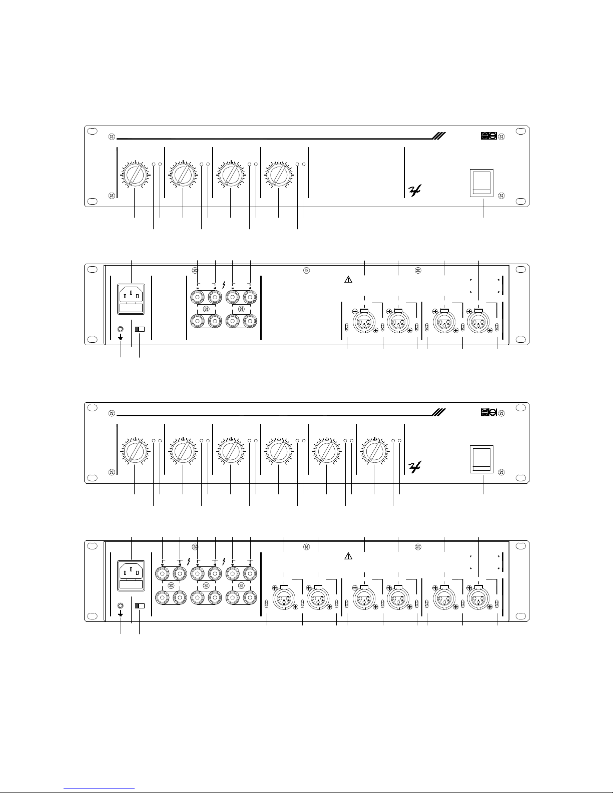
40
6.7. Function diagram
6.7. Diagrama de funcionamiento
6.7. Schéma de fonctionnement
6.7. Funktionsdiagramm
CLIP
4
0
1
2
3
SP CLIP
64
CLIPSP
6
010
9
8
7
1
2
3
9
7
10
1
8 2
3
CHANNEL 1
5
CHANNEL 2
5
SP
64
SP CLIP
64
2
0 10
9
8
7
0
1
3
10
9
8
7
CHANNEL 3
5
CHANNEL 4
5
POWER
4-80AMP
POWER AMPLIFIER
MULTICHANNEL
ON
OFF
CE EL R
VOL VOL VOL VOL
TO PREVENT FIRE OR SHOCK
FUSE: T 4 A 5x20
MAINS INPUT
GND
OFFON
GND LINK
CH 4 - CH 3 -
BRIDGED
OUTPUT
CH 2 - CH 1 -
BRIDGED
WARNING:
CHANNEL 1
MUST BE 4 OHM FOR STEREO AND 8 OHM FOR BRIDGE OPERATION.
REFER SERVICING TO QUALIFIED SERVICE PERSONNEL ONLY.
REPLACE FUSE WITH SPECIFIED TYPE ONLY.
MINIMUM NOMINAL LOAD IMPEDANCE
CHANNEL 3
DO NOT REMOVE COVERS. NO USER SERVICEABLE PARTS INSIDE.
BRIDGESTIN 4 LINK CH 2
IN 4
IMPORTANT:
CHANNEL 4
CAUTION:
CHANNEL 2
LINK CH 1
IN 3
IN 3 BRIDGE
ST
LINK CH 1IN 2 IN 1
IN 2
XLR CONNECTIONS
PIN 3 - NON PHASE
PIN 2 - PHASE
PIN 1 - GROUND
IN 1+IN 2
IN 1
THIS APPARATUS MUST BE EARTHED.
HAZARD, DO NOT EXPOSE THIS APPARATUS
TO RAIN OR MOISTURE TO AVOID RISK OF
ELECTRIC SHOCK DO NOT REMOVE COVERS.
CH 3 +CH 4 + CH 2 + CH 1 +
MINIMUM LOAD: 4 OHM STEREO, 8 OHM BRIDGE FOR BRIDGED OUTPUT USE RED POSTS ONLY.
CLIP
4
0
1
2
3
SP CLIP
64
CLIPSP
6
010
9
8
7
1
2
3
9
7
10
1
8 2
3
CHANNEL 1
5
CHANNEL 2
5
SP
64
SP CLIP
64
2
0 10
9
8
7
0
1
3
10
9
8
7
CHANNEL 3
5
CHANNEL 4
5
POWER
SP
64
SP CLIP
64
1
0
2
3
10
9
8
7
1
0
3
2
10
9
8
7
CHANNEL 5
5
CHANNEL 6
5
6-80A
CLIP
MP
POWER AMPLIFIER
MULTICHANNEL
ON
OFF
CE EL R
VOL VOL VOL VOL VOL VOL
TO PREVENT FIRE OR SHOCK
LINK CH 4
FUSE: T 6.3 A 5x20
MAINS INPUT
GND
BRIDGED
OFFON
GND LINK
CH 6 - CH 4 -CH 5 - CH 3 -
BRIDGED
OUTPUT
BRIDGE
CH 2 - CH 1 -
BRIDGED
IN 6
ST IN 6
CHANNEL 6
WARNING:
CHANNEL 1
MUST BE 4 OHM FOR STEREO AND 8 OHM FOR BRIDGE OPERATION.
REFER SERVICING TO QUALIFIED SERVICE PERSONNEL ONLY.
REPLACE FUSE WITH SPECIFIED TYPE ONLY.
MINIMUM NOMINAL LOAD IMPEDANCE
CHANNEL 3
DO NOT REMOVE COVERS. NO USER SERVICEABLE PARTS INSIDE.
BRIDGEIN 5 LINK CH 3
IN 5 ST
CHANNEL 5
IN 4 LINK CH 2
IN 4
IMPORTANT:
CHANNEL 4
CAUTION:
CHANNEL 2
LINK CH 1
IN 3
IN 3 BRIDGE
ST
LINK CH 1IN 2 IN 1
IN 2
XLR CONNECTIONS
PIN 3 - NON PHASE
PIN 2 - PHASE
PIN 1 - GROUND
IN 1+IN 2
IN 1
THIS APPARATUS MUST BE EARTHED.
HAZARD, DO NOT EXPOSE THIS APPARATUS
TO RAIN OR MOISTURE TO AVOID RISK OF
ELECTRIC SHOCK DO NOT REMOVE COVERS.
CH 3 +CH 6 + CH 4 +CH 5 + CH 2 + CH 1 +
MINIMUM LOAD: 4 OHM STEREO, 8 OHM BRIDGE (RED POSTS ONLY)
1 4 7 10 13 16
21
3 6
5
9
8
12
11
15
14
18
17
19
22 23 24 25 26 27 28 29 30 31 32
20
34
33 35
36 37 38 39 40 41 42 43 44
2
20 23 24 25 26
333435
32313029
39 40 41 42 43 44
1031
2
456 7 9
8 11
12 19
Page 41
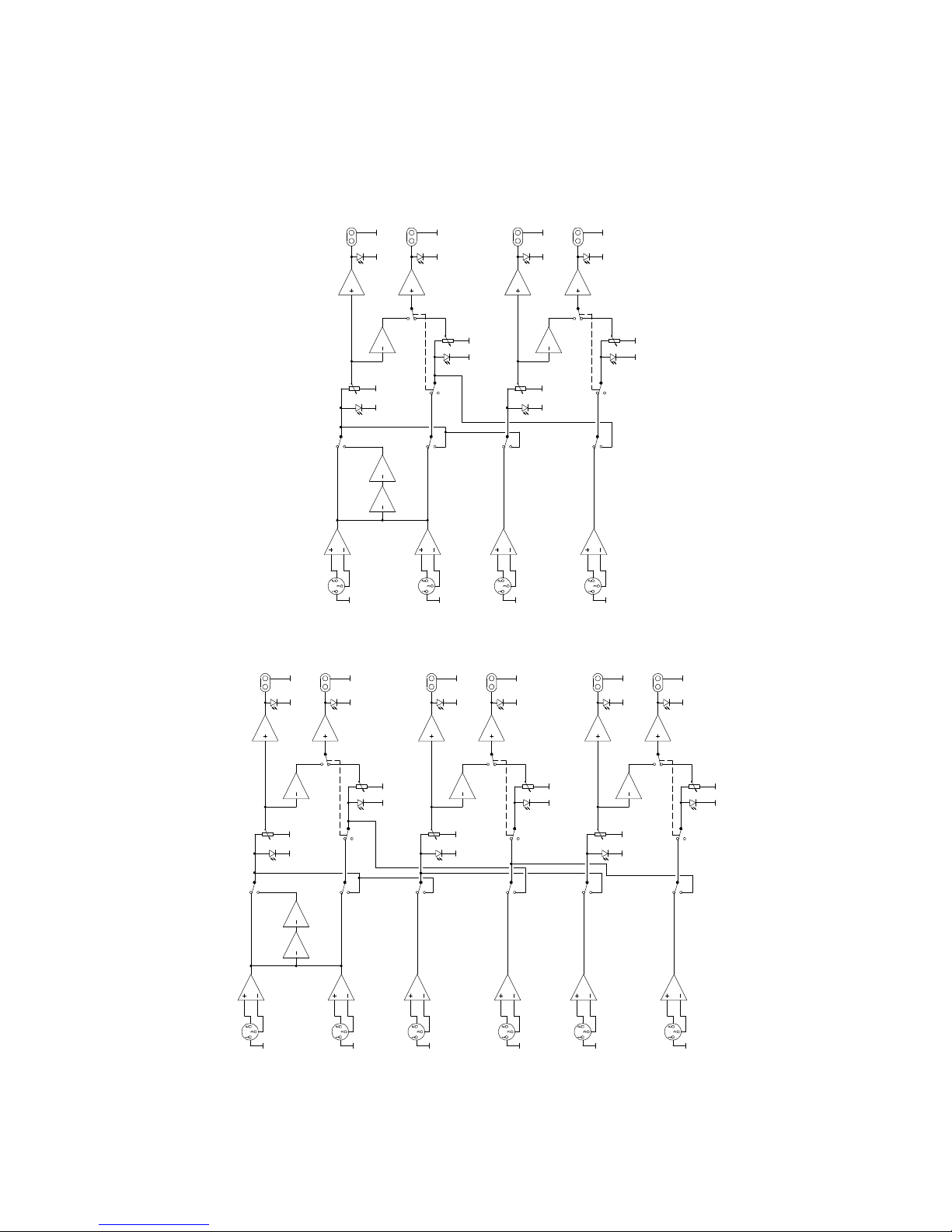
41
6.8. Block diagram
6.8. Diagrama de bloques
6.8. Blocs de diagrammes
6.8 Blockschaltbild
IN 1
IN 2
OUT 1
OUT 2
CLIP
CLIP
S.P.
VOL 1
VOL 2
IN 1
IN 1+IN 2
IN 2
LINK IN 1
STEREO
BRIDGE
BRIDGE
STEREO
IN 4
IN 4
LINK IN 2
BRIDGE
STEREO
IN 3
LINK IN 1
IN 3
VOL 3
VOL 4
STEREO
BRIDGE
CLIP
OUT 4
CLIP
OUT 3
IN 5
IN 6
IN 6
LINK IN 4
LINK IN 3
STEREO
BRIDGE
VOL 5
IN 5
VOL 6
BRIDGE
STEREO
CLIP
CLIP
OUT 6
OUT 5
MPA6-80
MPA4-80
S.P.
S.P.
S.P.
S.P.
S.P.
IN 1
IN 2
OUT 1
OUT 2
CLIP
CLIP
S.P.
S.P.
VOL 1
VOL 2
IN 1
IN 1+IN 2
IN 2
LINK IN 1
STEREO
BRIDGE
BRIDGE
STEREO
IN 4
IN 4
LINK IN 2
S.P.
BRIDGE
STEREO
IN 3
LINK IN 1
IN 3
S.P.
VOL 3
VOL 4
STEREO
BRIDGE
CLIP
OUT 4
CLIP
OUT 3
Page 42

42
ECLER Laboratorio de electro-acústica S.A.
Motors 166-168, 08038 Barcelona, Spain
INTERNET http://www.ecler.es E-mail: [email protected]
50.0012.0100
 Loading...