

Page 1

USER MANUAL
MANUAL DE INSTRUCCIONES
NOTICE D’EMPLOI
BEDIENUNGSANLEITUNG
Page 2

Page 3

3
LIST OF CONTENTS
1. IMPORTANT NOTE 04
1.1. Precautions 04
2. INTRODUCTION 04
3. INSTALLATION 05
3.1. Location, assembly, ventilation 05
3.2. Mains connection 06
3.3. Signal input connections 06
3.4. Subsonic filter 06
3.5. Limiter circuit 06
3.6. Output connections 07
4. OPERATION AND USAGE 07
4.1. Start up 07
4.2. Input attenuators 07
4.3. Indicators 07
5. CLEANING 08
6. FUNCTION LIST 09
7. FUNCTION DIAGRAM 09
8. TECHNICAL CHARACTERISTICS 31
9. DIAGRAMS 32
9.1. Figures 32
9.2. Block diagram 34
All numbers subject to variation due to production tolerances. ECLER S.A. reserves the right to make changes or
improvements in manufacturing or design which may affect specifications.
Page 4

4
1. IMPORTANT NOTE
Congratulations! You are the owner of a carefully designed and manufactured equipment. We thank you for
trusting on us and choosing our amplifier DPA SPM (All purpose) (Switching Power Mosfet).
In order to obtain maximum operativity and perfect functioning order, it is most important to carefully read
all considerations taken into account in this manual before connecting this amplifier.
We recommend our authorised Technical Services if any maintenance task should be needed so that
optimum operation shall be achieved.
DPA series amplifiers come with a 3-year warranty.
1.1. Precautions
The DPA600/1000/1400/2000 consumes a maximum power of 830VA / 1250VA / 1720VA / 3115VA, we
therefore recommend a mains wire not inferior to 2,5mm
2
and a (circuit breaker) superior to 10A/220VAC
(15A/220VAC DPA2000) (data for one amplifier).
The amplifier should have an earth connection in good conditions (earth resistance, Rg=30 or less).
The environment must be dry and dustless. Do not expose the unit to rain or water splashes, and do not
place liquid containers or incandescent objects like candles on top of the unit. Do not obstruct the
ventilation grilles with any kind of material.
In case there is some type of intervention and/or connection-disconnection of the amplifier, it is most
important to previously disconnect the mains power supply.
Do not manipulate the output terminals to the loudspeakers when the amplifier is switched on, there are
voltages up to 400Vpp. The output cabling should be connected by a qualified technician. Otherwise only use premade flexible cables. There are no user serviceable parts inside the amplifier.
2. INTRODUCTION
With the PAM amplification series, ECLER introduced a new concept to the world of professional audio:
The use of switching field effect transistors. The integration of these parts for audio applications represents a firm
and spectacular enhancement comparing to conventional amplifiers. These advantages can be outlined as follows:
a) Lower internal resistance than bipolar transistors, which leads to less heating of the amplifier and more
powerful and controlled bass.
Conventional Mosfets have a 4 to 7 times higher internal resistance than switching Mosfets.
b) The extremely high speed of these devices gives a transparency to the upper frequencies till now only
achieved by tube amplifiers. This fact also reduces TIM (transitory intermodulation) to very low levels.
The SPM-Technology (Switching Power Mosfet) has been developed and patented by ECLER Laboratorio
de Electro-Acústica, S.A.
The DPA power amplifier line is yet another step forward in the evolution of the SPM technology.
DPA amplifiers introduce innovations which probably make them one of the most reliable amplification lines
of its class.
SOA Contour following protection
The SOA is the safe operating area of transistors. A good protection system should respect this area and
its shiftings, as the SOA changes as a function of the operating temperature. So, at 80°C it is considerably
narrower than a 25°C, the start-up temperature. Some manufacturers decide to use protection systems which
compromise on the performance of the components. You get a fair protection, but the performance remains
mediocre. Others prefer to leave "dark" areas between the safe operating area and the activation of protection,
which is very risky indeed.
The new SOA contour following protection systems built into the DPA amplifiers guarantees total protection
of the amplifier at any output power, load or operating temperature, as the intelligent electronic circuitry
permanently watches for changes in the safety area, adapting itself to any situation.
The best Damping in an amplifier of its class. In the DPA series, the typical output relays have been
substituted with an electronic CROW BAR system. This device shunts to ground any signal in case of high voltages
which could damage the connected speakers. Any kind of relay introduces a mechanical contact in the path of the
audio signal to the loudspeakers. This contact implies a certain degree of wearing and an important reduction of the
amplifier's damping factor.
Page 5

5
Ecler DPA2000 makes use of N-channel mosfets. This technology, which has been successfully implemented
in the industrial product line "enviro", allows for very high output power without the use of bridge configurations. The
DPA2000 keeps its “All the Power All the Time” philosophy, even when driving 4 ohm speakers with a musical
programme at maximum level.
The DPA power amplifiers feature an expansion slot at the rear panel which is specially designed for the
installation of the UCM or AMIC processor modules.
The stereo processor module UCM20 “Universal Crossover Module” is a card that has been specially
designed to fit into ECLERs DPA Series SPM Technology power amplifiers. A power amplifier with built-in UCM20
may reproduce either the low or high frequencies, as required. The two outputs additionally allow feeding the
filtered signal to an external amplifier.
The stereo digital processor module AMIC is a card that has been specially designed to fit into ECLERs
DPA Series SPM Technology power amplifiers and can be totally configured through Eclers “amic:lab” software. Its
exceptional audio processing features make it a particularly versatile tool:
- Equalizer with 10 filters
- Crossover with variable filter slopes
- Delay
- Phase inversion
- Signal generator
- Remote level control
Please refer to your Ecler distributor if you need to install a UCM or AMIC processor module inside a DPA
power amplifier.
3. INSTALLATION
3.1. Location, assembly, ventilation
The DPA600/1000/1400/2000 amplifiers are 2 RU high 19'' rack modules.
It is important that the amplifier, as a heat source, is not placed next to other equipment nor exposed to
high temperatures. Therefore, the ventilation path should be kept free to allow fresh air entering the forced
ventilation tunnel. This system takes air from the unit's backside, bringing it directly to the power amp modules and
distributing it to the transformer and capacitors and then obliging it to pass trough the MOSFET cooling tunnel to
finally blow out of the front panel. In case of rack mounting, this system avoids heat accumulation inside the unit
and thus increases lifetime of electrolytic capacitors. It is recommended to place power amplifiers on top of other
equipment and not underneath.
All DPA amplifiers are supplied with plastic washers in order not to damage the rack ears when tightening
the screws.
Page 6

6
3.2. Mains connection
The DPA amplifiers are fed with alternate currents, depending on the country, of 110-120, 220-240V
47-63Hz. (see characteristics in the back of the unit) consuming:
MODEL DPA600 DPA1000 DPA1400 DPA2000
CONSUMPTION 830VA 1250VA 1720VA 3115VA
The mains cables must not be near the shielded cables carrying the audio signal, as this could cause
humming.
3.3. Signal input connections
The signal input connectors are of XLR-3 type (10), electronically balanced. The pin assignment is as
follows:
HOT or direct signal > Pin 2
COLD or inverted signal > Pin 3
GROUND > Pin 1
For unbalanced connection short-circuit pin 3 to pin 1.
The “STK OUTPUT” (9) are in parallel with the inputs and are used to supply the same input signal to other
amplifiers or sound systems. This signal output connectors are of jack 1/4" type. The pin assignment is as follows:
HOT or direct signal > Tip
COLD or inverted signal > Ring
GROUND > Body
The input impedance is 22K (balanced) with a nominal input sensitivity of 0dBV(1V). This impedance
makes possible to parallel several amplifiers without loosing audio quality.
3.4. Subsonic filter
This filter cuts off inaudible frequency components which when amplified suppose a risk of damage to the
low frequency speakers as they generate excessive excursions of the woofer's diaphragm. The DPAs feature a
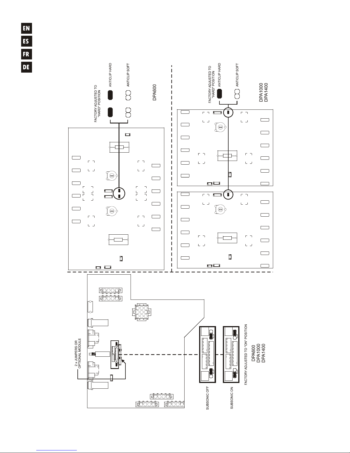
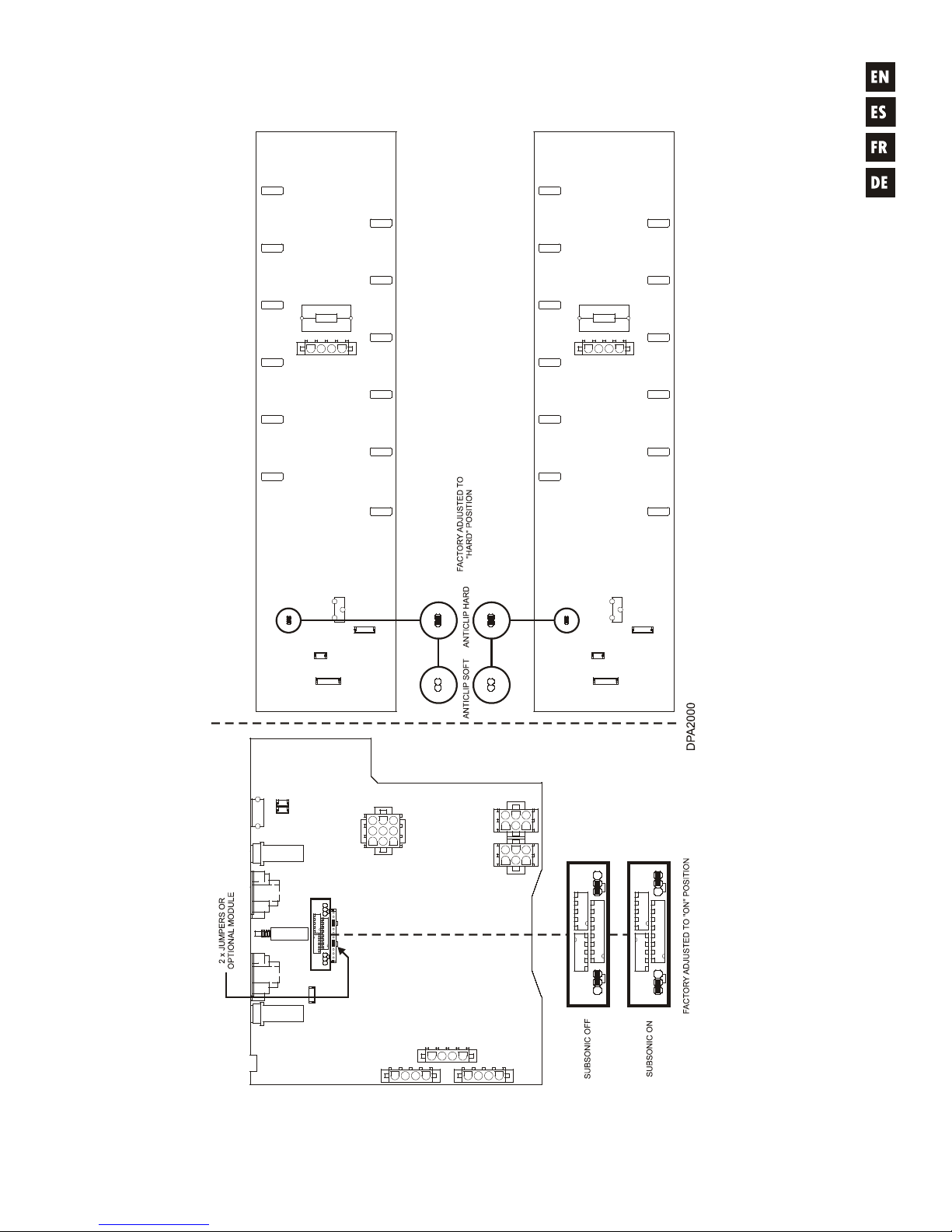
switchable, Butterworth shaped Subsonic Filter located inside the unit (see fig.) with a 25Hz cut-off frequency and
18dB/oct slope.
Subsonic filters are very important when playing back vinyl records because the phono cartridges are
specially sensitive to feedback and acoustic coupling at very low frequencies.
DPA amplifiers are delivered with switched ON Subsonic Filter.
CAUTION: Changes on the Subsonic Filter have to be performed by a qualified technician.
3.5. Limiter circuit
This system is an always active protection inside the DPA series of amplifiers. The ANTICLIP circuitry
constantly analyses harmonic distortion caused by excessive signal excursion at the power amplifier's output and
automatically reduces the input level in order never to exceed 1% total harmonic distortion. The DPA range of
amplifiers are delivered with the anticlip system adjusted at a threshold of 1% THD (hard limiting). However, this
value can be switched to a softer limiting (5% THD) via an internal jumper (see fig.).
The great convenience of such a circuit in any kind of installation has to be remarked: The clear advantage
of a limiting system in front of conventional compressors is that the former does practically not alter the dynamic
range, acting only when the distortion threshold is reached.
CAUTION: Changes on the ANTICLIP configuration have to be performed by a qualified technician.
Page 7

7
3.6. Output connections
The OUTPUT section on the rear panel features Speakon connectors (12).
Whenever you need to operate the amplifier in BRIDGED mode (mono or bridged), you must set the
“STEREO BRIDGED" Switch (11) to BRIDGED. The input signal is taken from the CHANNEL 1 connector and the
signal output to the loudspeaker is on pins 2+ and 2- of the Speakon connector “CH1”. The same contacts (2+ and 2-)
of the Speakon connector of CH2 also carry the bridged signal in order to facilitate the parallel connection of
loudspeakers.
ATTENTION: Terminals 1+, 1- must only be used in STEREO operation and terminals 2+, 2- in BRIDGED
operation. Other combinations would lead to poor output quality.
Please make sure that the resulting impedance of your installation, when the amplifier is operating in BRIDGE
mode, is never lower than 4 Ohm (8 Ohm recommended).
The connection cable that joins the amplifiers outputs and the loudspeakers must be of good quality,
sufficient section and as short as possible. This is most important when the distances to cover are long ones i.e. up
to 10 meters it is recommended to use a section not inferior to 2.5mm
2
and for superior distances 4mm2.
4. OPERATION AND USAGE
4.1. Start up
Pushing the POWER (5) button lights up the integrated pilot light and both red CLIP PROT (2) LEDs during
the approximately 10 seconds needed to stabilize all voltages. The CLIP PROT LEDs will then turn off meaning
that the amplifier is now operative.
In a complete audio installation, it is important to start up the equipment in the following sequence: sound
sources, mixer, equalizers, active filters and finally power amplifiers. To turn them off the sequence should follow
an inverse pattern.
4.2. Input attenuators
This consists of rotative potentiometers, situated on the front panel (1).
These attenuators enable the connection of different types of mixing tables, independent regulation level
and loudspeaker connections that allow an inferior power level that the level already supplied by the power
amplifier at its maximum power, with no danger of damaging, by careless handling, the volume of the pre-amplified
mixer.
Inside the device's packaging you will find a little plastic bag containing 2 transparent caps which protect the
input attenuation settings from unwanted manipulation. These caps are transparent in order to let you visualize the
current settings.
Once inserted, they cannot be removed with bare fingers, for this purpose, a small screwdriver is needed.
4.3. Indicators
The DPA amplifiers are equipped with a simple but efficient combined indicators system.
Indicator CLIP/PROT (2) function as PROTECTION indicator.
They point to the lack of signal at the speaker outputs. These indicators may light up due to following reasons:
1. From the moment the machine is switched on, until stand by period finalise that is necessary for the
stability of the internal tensions of the power amplifier.
2. Because the amplifier output has short circuited.
3. If the amplifier is giving a continuous voltage or is of very low frequency, this could damage the
loudspeakers.
In any case, should these indicators permanently light up, it is a sign of malfunctioning and its cause should
be investigated.
Page 8

8
CLIP/PROT indicators functioning as CLIP indicator.
These illuminate when the signal given to the loudspeakers is 1.5dB before the real clip. This CLIP system
takes into account the possible variations in the mains voltage always giving a real indication even if the electric
mains varies. It is normal that working at high power levels, the CLIP indicators illuminate at the rhythm of the low
frequencies which are the ones that passes major energetic contents. Make sure these indicators are not
permanently illuminated.
THERMAL protection indicator (3)
Alerts of the tunnel cooling temperature when it has risen above 90 centigrade degrees. The amplifier will
then start up automatically when the temperature descends to 75 centigrade degrees.
The DPA power amplifiers feature separate thermal protection systems per channel. They operate
independently, meaning that if one channel triggers its protection system, the other one can perfectly continue its
normal operation.
SP Signal Presence indicator (4)
It points to the existence of signal at the amplifier input. These indicators light up when the input signal
surpasses -40dB.
5. CLEANING
The front panel should not be cleaned with dissolvent or abrasive substances because silk-printing could be
damaged. To clean it, use a soft cloth slightly wet with water and neutral liquid soap; dry it with a clean cloth. Be
careful that water never gets into the amplifier through the holes of the front panel.
Page 9
9
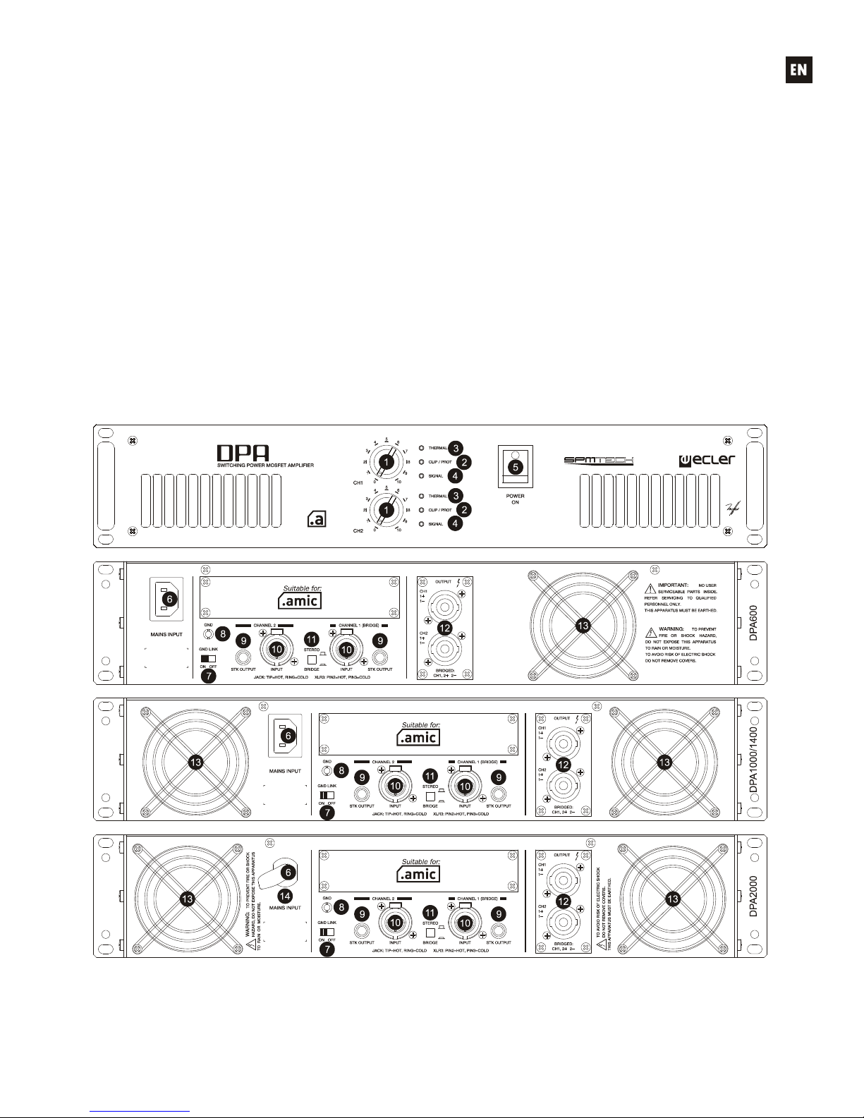
6. FUNCTION LIST
1. Input attenuator
2. Combined clip and protection indicator, CLIP/PROT
3. Thermal protection indicator, TH
4. Signal present indicator, SP
5. Illuminated mains switch
6. Mains socket
7. Switch to disconnect chassis earth/electrical Ground, GND LINK
8. Earth terminal, GND
9. Jack output connector to other amplifiers, STK OUTPUT
10. Input XLR connector, CHANNEL
11. Bridge/mono selector switch
12. Speakon connectors to the loudspeakers
13. Fan
14. Mains cable
7. FUNCTION DIAGRAM
Page 10

31
8. TECHNICAL CHARACTERISTICS 8. CARACTERÍSTICAS TÉCNICAS
8. CARACTERISTIQUES TECHNIQUES 8. TECHNISCHE DATEN
DPA600 DPA1000 DPA1400 DPA2000
POWER 20-20kHz 1% THD
2 Stereo 410 WRMS 682 WRMS 990 WRMS 1420 WRMS
4 Stereo 275 WRMS 440 WRMS 635 WRMS 940 WRMS
8 Stereo 180 WRMS 275 WRMS 395 WRMS 550 WRMS
8 Bridged 550 WRMS 882 WRMS 1270 WRMS 1880 WRMS
Peak Power 2/1kHz 0.98Kw 1.5Kw 2Kw 2.95Kw
Frequency response (-1dB) 7Hz-50kHz 7Hz-50kHz 7Hz-50kHz 6Hz-50kHz
High pass filter (-3dB) 25Hz/Butt./18dB/oct.
THD+Noise @ 1kHz Full Pwr. <0.03% <0.03% <0.03% <0.07%
Imd. Dist. 50Hz & 7kHz, 4:1 <0.05% <0.08% <0.08% <0.08%
TIM 100 <0.01% <0.01% <0.01% <0.01%
S+N/N 20Hz-20kHz @ 1W/4 >85dB >85dB >85dB >85dB
Damping factor 1kHz @ 8 >300 >300 >300 >300
Slew Rate ±60V/µs ±65V/µs ±75V/µs ±80Vµs
Channel crosstalk @ 1kHz >75dB >75dB >75dB >75dB
Input connector XLR3 balanced
Input CMRR/ref. Max. PWR) >60dB @ 1kHz
Input Sensitivity / Impedance 0dBV/>22k
Signal present indicator -40dB
Output connectors Speakon
Clip indicators -1.5dB real clip
Anticlip limiter 1% & 5% aprox.
Mains Depending on your country. See characteristics in the back of the unit.
Power consumption:
(pink noise, 1/8 power @ 4ohm) 479VA 746VA 1023VA 1426VA
(pink noise, 1/3 power @ 4ohm) 728VA 1122VA 1548VA 2160VA
(max. Out) 830VA 1250VA 1720VA 3115VA
Dimensions
Panel 482.6x88 mm
Depth 420 mm 420 mm 420 mm 470 mm
Weight 12.7kg 16.6kg 19.3kg 22.7kg
Page 11
32
9. DIAGRAMS 9. DIAGRAMAS
9. SCHÉMAS 9. DIAGRAMME
9.1. Figures 9.1. Figuras
9.1. Schémas 9.1. Abbildungen
Page 12
33
Page 13
34
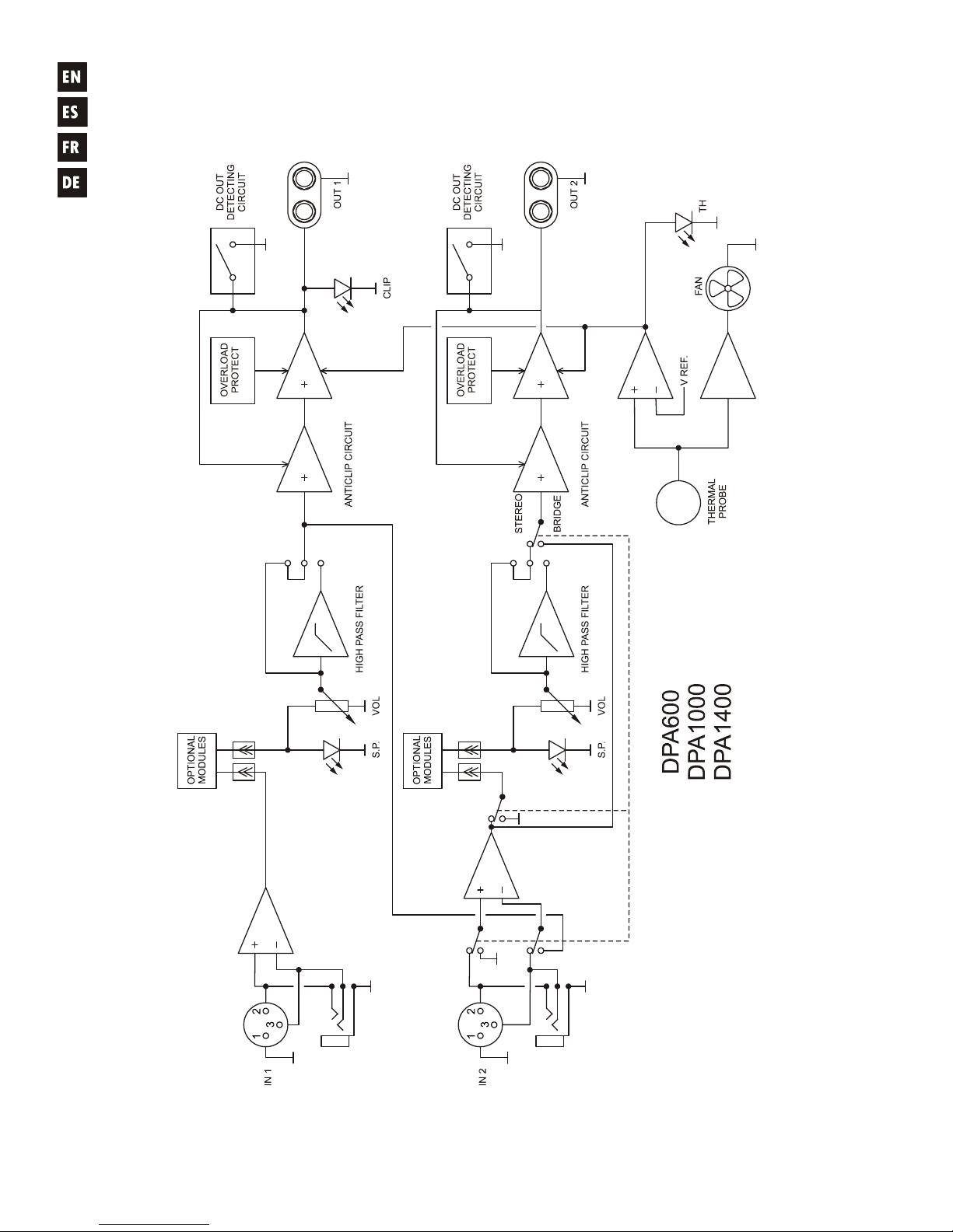
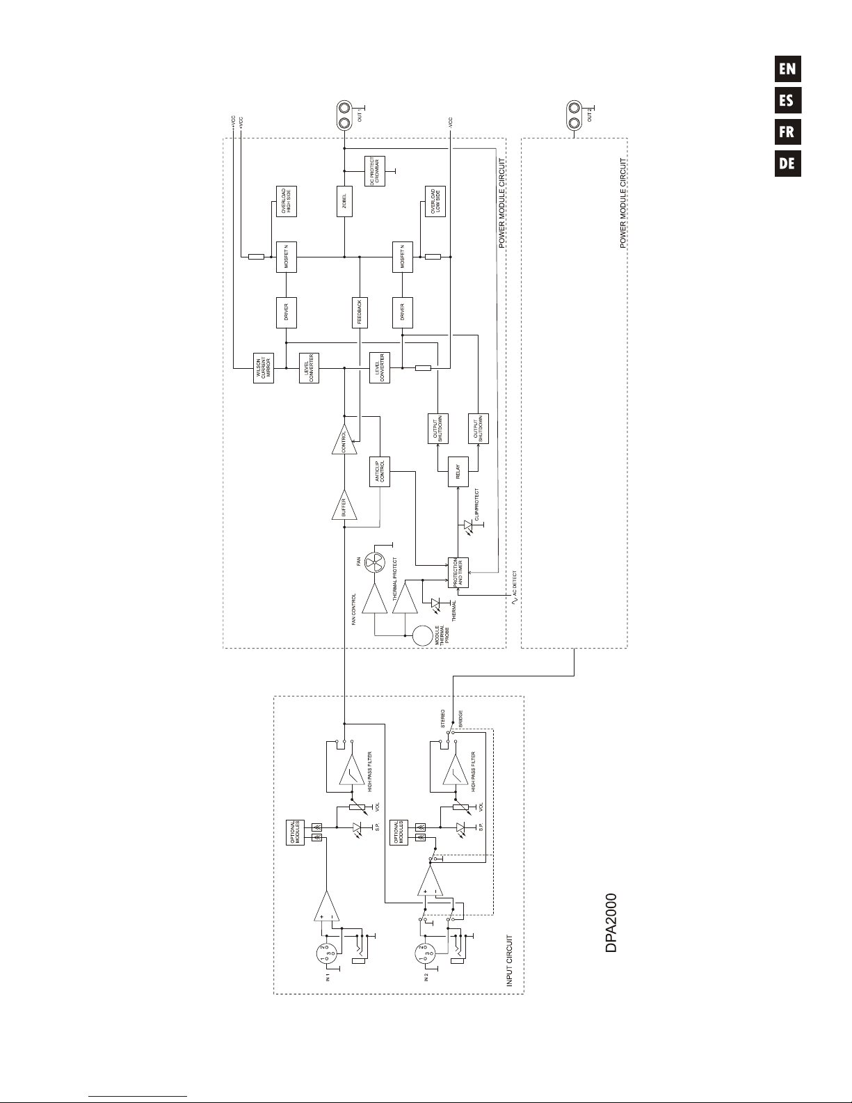
9.2. Block diagram
9.2. Diagrama de bloques
9.2. Diagramme de blocs
9.2. Blockschatbild
Page 14
35
Page 15

ECLER Laboratorio de electro-acústica S.A.
Motors 166-168, 08038 Barcelona, Spain
INTERNET http://www.ecler.com e-mail: [email protected]
50.0093.01.04
 Loading...