

Page 1
USER MANUAL
MANUAL DE INSTRUCCIONES
MANUEL UTILISATEUR
BEDIENUNGSANLEITUNG
Page 2

Page 3

3
User Manual Contents
1. IMPORTANT REMARK 4
2. INSTALLATION 5
3. INTRODUCTION 5
4. FRONT PANEL 6
5. REAR PANEL 8
6. SETUP MODE 9
7. INPUTS 20
8. OUTPUTS 23
9. PROGRAMMING EXAMPLE 33
10. SOFTWARE 41
11. TECHNICAL CHARACTERISTICS 207
All numbers subject to variation due to production tolerances. ECLER S.A. reserves the right to make changes or
improvements in manufacturing or design which may affect specifications.
Page 4
4
1. IMPORTANT REMARK
Congratulations! You are the owner of a carefully designed and manufactured equipment. We
thank you for trusting in us and choosing our DP300 processor.
In order to get the optimum operation and efficiency from this unit, it is VERY IMPORTANT
- before you plug anything - to read this manual very carefully and bear in mind all considerations
specified within it.
We strongly recommend that its maintenance be carried out by our Authorised Technical
services.
Precautions
This apparatus must be earthed through its mains cable.
Do not expose the unit to rain or water splashes, and do not place liquid containers or
incandescent objects like candles on top of the unit.
Should any connection / disconnection task be done, always disconnect the unit from the mains
supply.
There are no user serviceable parts inside the unit.
Ground Loops
Care should be taken, so that the different mechanical and electrical grounds, as well as the
chassis and ground connections arriving to the device, to be independent from each other.
Ground loops can be easily detected through a low frequency hum noise (50Hz). Depending
on the level of this noise, it can interfere on the music quality.
Audio connections
Usually, many people do not care enough about the quality of cables. Many times, because of a
bad connection or bad quality cables, there can be important problems during the music reproduction.
Cleaning
The control panel must not be cleaned with any dissolvent, abrasive or petroleum derived
substance else paint and silk-printing could be damaged. Whenever cleaning should be necessary use
a soft cloth slightly wet with water and neutral liquid soap. Be careful that no liquid gets into the unit
through its orifices. Never use sharp or erosive objects to scratch the control panel.
Page 5

5
2. INSTALLATION
The DP300 can be mounted in a standard 19” rack (482.6 mm) taking up one height unit
(44 mm). The plastic washers which are provided can be used to protect the unit from damage during
rack-mounting.
For professional use it is recommended to place the processor in the same rack as the power
amplifiers.
Given the small power consumption of the unit, no ventilation is required. Nevertheless, it is
advisable not to expose the unit to extreme temperatures as well as ensure a dry and dust-free
operating environment.
It is important not to place the processor next to electrical noise sources such as transformers,
voltage dimmers, motors, etc. or their mains supply cables. The metal cover of the device should never
be removed under any circumstance for that same reason.
The DP300 operates with alternate current (AC) between 90 and 264V at 47 to 63Hz. This
device features an oversized power supply which adapts itself to any mains voltage around the world,
without the need of manual adjustment.
Even though the noise produced by powering up is minimum, it is always advisable to follow this
power up sequence: signal sources, mixing unit, processor and, finally, power amplifiers. The power
down sequence must follow exactly a reverse order. By closely following this sequences, all peaks or
transients produced by switching on and off devices do not affect the next devices in the chain and, of
course, never reach the loudspeakers, which are extremely sensitive about this.
3. INTRODUCTION
DIGITAL LOUDSPEAKER SYSTEM PROCESSOR DP300
The ultimate solution for comprehensive adjustment and control of complex loudspeaker systems
with remote control using the dp:lab software. Excellent audio quality and dynamics. The DP300 uses
high quality S-? type AD/DA converters, 48kHz sampling rate and 2 x 24bit DSP processing.
Main features:
• Superb audio quality thanks to its 24-bit DSP and 48kHz sampling rate.
• 2 inputs and 6 outputs. Operating modes: Mono, 2x3 way and 3x2 way.
• Selectable Crossover slopes of 6,12,18,24 or 48dB per octave and filter types: Butterworth,
Linkwitz-Riley or Bessel.
• Parametric or shelving equalizer for smooth system frequency response up to 38 bands.
• Digital gain adjustment range from -15dB to +15dB.
• Limiter and compressor. Compressor output with adjustable threshold.
• Phase Invert option per output.
• Electronically balanced inputs and outputs.
• Up to 635ms signal delay per signal path.
• 60 memory bank locations for user programs. With the use of the dp:lab software included with
the DP300, virtually unlimited programs can be stored in the computer hard drive.
• 3-Level Locking system. 2 protection mechanisms with password.
• 2x16 character blue backlit LCD.
• MIDI and RS-232 control.
• dp:lab software for remote control and programming of all parameters of the DP300 unit.
Page 6
6
4. FRONT PANEL
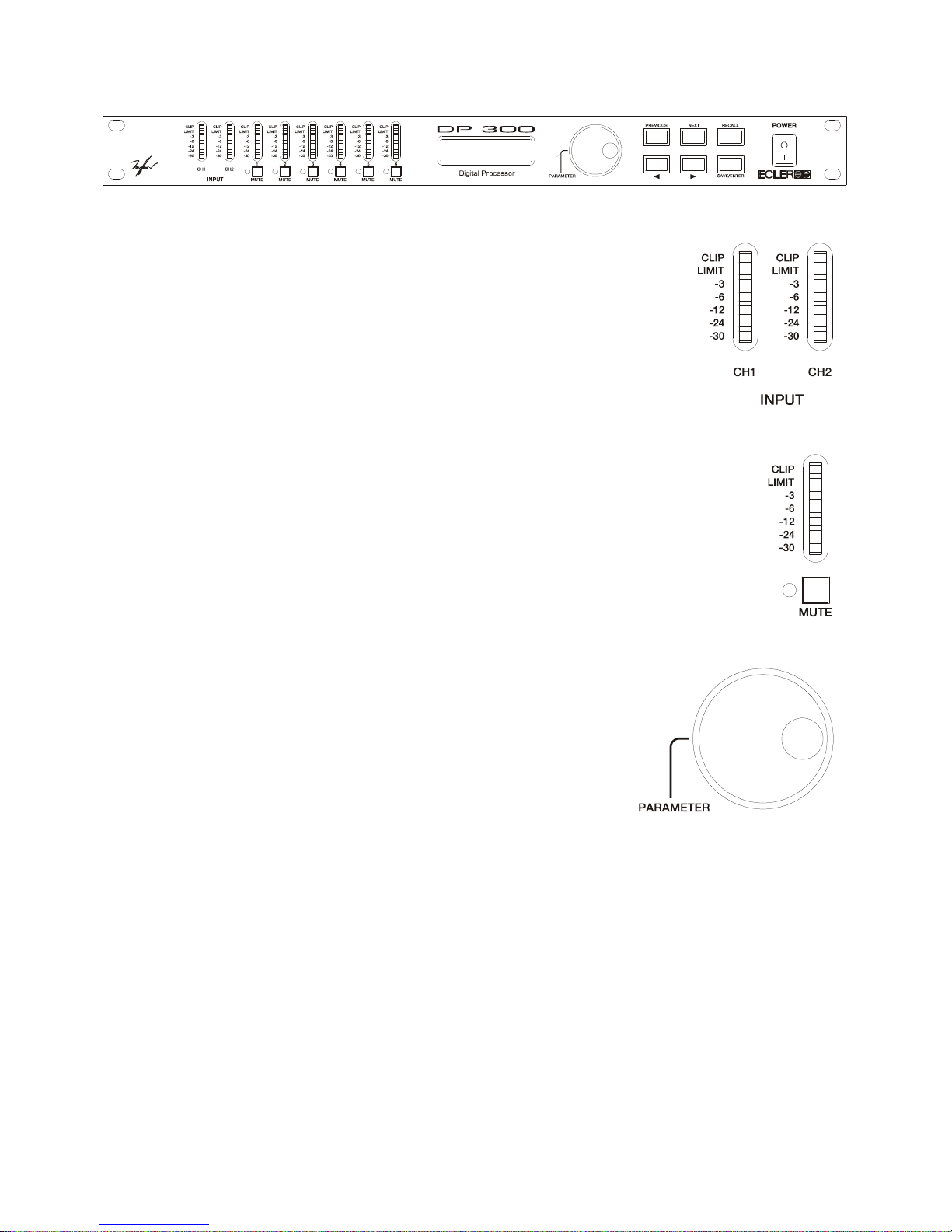
Input VU-meter
The input VU-meter lets you visually monitor the input signal level, having
indications for –30dB, -24dB, -12dB, -6dB and –3dB. Furthermore, LIMIT and
CLIP indicators are provided. Apart from normal operation for input level
monitoring, digital clipping is also shown here. If the CLIP led lights up but the
LEDs below do not, this means that the digital audio signal is clipping (DSP) and
not the analogue input stage. This may happen if inadequate EQ or excessive
gain is applied to any of the outputs.
Output VU-meter
The output VU-meter lets you visually monitor the output signal level relative to a
trigger threshold adjustment. If a +4dB signal is sent to an output with a trigger threshold of
0dB, the –6dB led will light up.
MUTE Buttons
By pressing these buttons (one for each output channel) the selected channel is
muted. If the output is muted, the associated led next to the button is lit.
Rotary encoder wheel
By turning the encoder wheel clockwise or counter-clockwise,
parameters and values shown on the display can be incremented or
decremented. The encoder wheel also features a push-button function.
At each press, the parameters for the next input or output channel are
accessed cyclically. By pressing and simultaneously turning the wheel,
inputs and outputs can be accessed more quickly.
Page 7
7
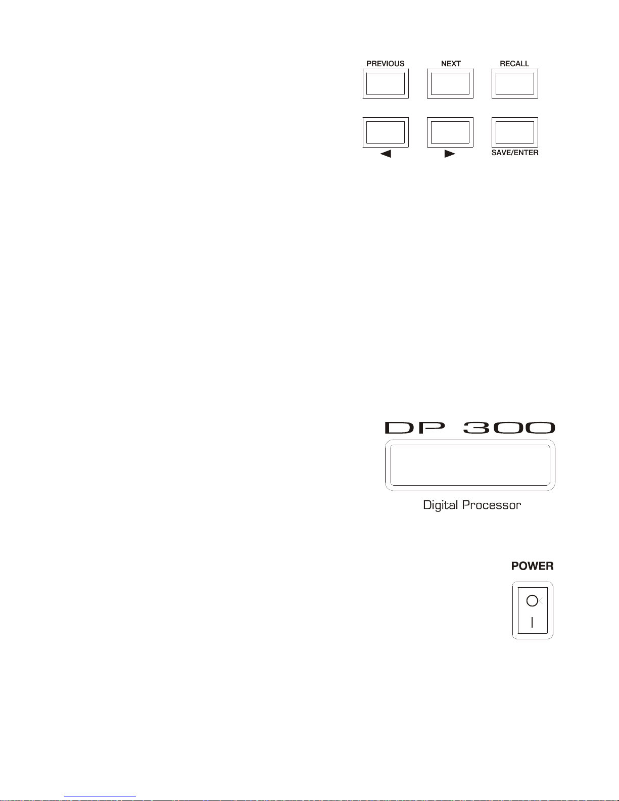
PREVIOUS and NEXT keys
By pressing these keys, individual settings of a certain
menu item chosen by pressing the encoder can be accessed.
Example: If you are in the SETUP screen, PREVIOUS and
NEXT will lead you to the individual adjustable parameters
inside the SETUP menu.
? and ? keys
These buttons can be used to perform adjustments on the selected parameter that is shown in
the LCD display. Numeric parameters will increase or decrease their value, while in other cases, an
option list will be offered. Pushing these buttons is equivalent to turning the encoder wheel.
SAVE/ENTER key
This key is used to store new programs to the internal memory of the device. The ENTER key is
also used to confirm certain actions.
RECALL Key
Press this button whenever you wish to recall a previously saved program from the internal
memory of the DP300. If the device is new, no programs are found in memory. To recall a program
stored in memory, first press RECALL, then select the desired program using PREVIOUS and NEXT
and once selected, press RECALL again.
LCD Display
The blue backlit LCD features two rows of 16 characters.
Four different information areas an be found:
1. The upper left part shows the input (IN) or output (OUT)
channel currently being edited.
2. The lower left part shows the currently selected parameter
of the currently selected input or output.
3. The lower right part shows the parameter value.
4. The upper right portion shows information relative to the current status of the DP300. If any
modification to the current program has been done, an asterisk appears.
ON-OFF switch
Simply turns on or off the unit. Please ensure the correct electrical installation before
switching ON the system.
Page 8
8
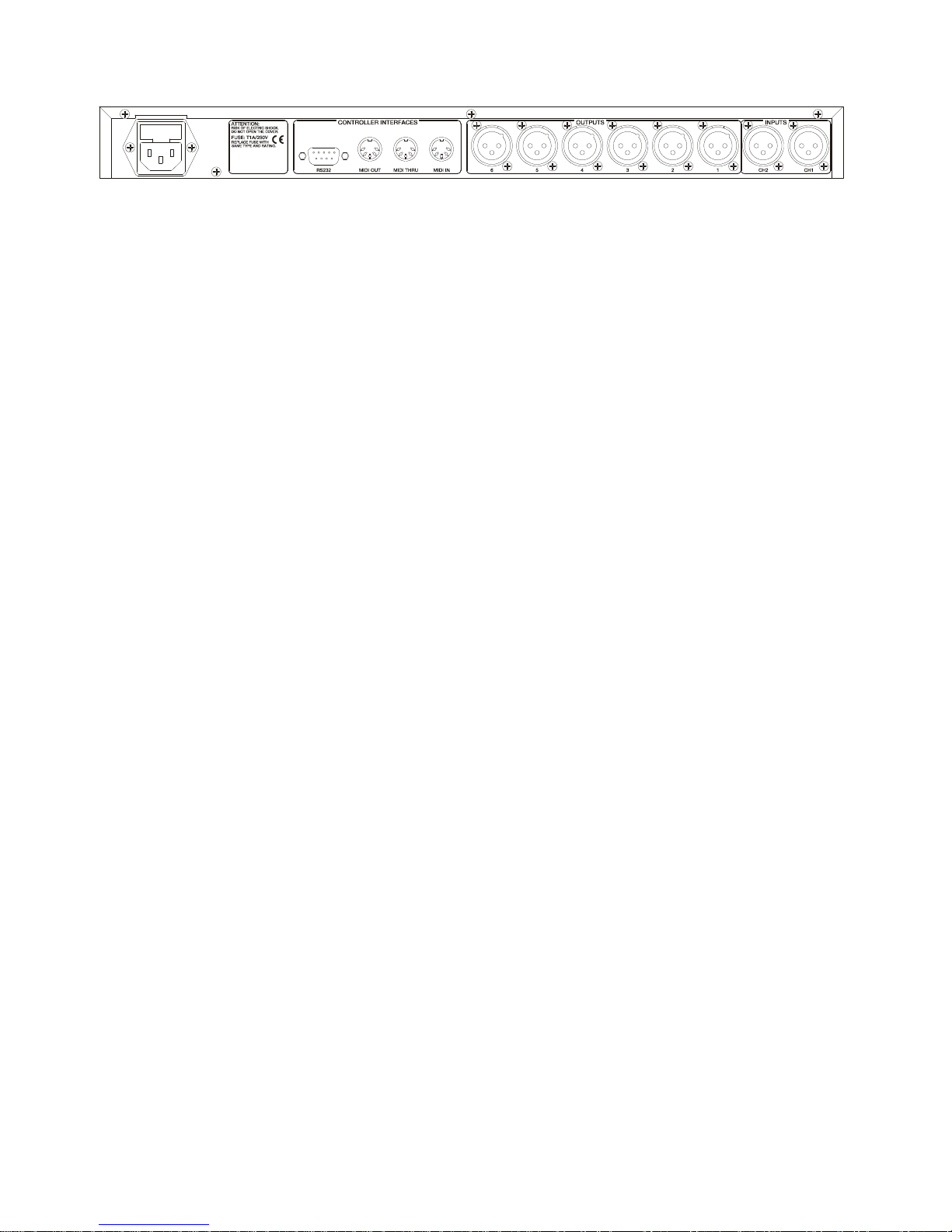
5. REAR PANEL
The rear panel features following connections:
Mains socket
The DP300 features a 3-pin IEC socket for mains supply. The fact of having a switched mode
power supply, allows the use of a wide range of mains specifications: from 90 to 264 VAC at frequencies
between 47 and 63 Hz. Before switching on the unit, please ensure that the DP300 is connected to earth
and that the electrical installation fulfils the local safety regulations.
RS-232 socket
A 9-pin SUB-D connector for serial RS-232 communication is provided at the rear panel. This
connector allows bi-directional communication between the DP300 and a PC in order to remotely control
the parameters of the processor via software.
MIDI Sockets
Three 5-pin DIN connectors provide MIDI communication. MIDI IN, MIDI OUT and MIDI THRU
are provided.
Input Connectors (CH1, CH2) and Output Connectors (Output 1-6)
The DP300 has two inputs (CH1 and CH2) on three-pin female XLR sockets. The pin layout is
following: Pin 1 is Ground, Pin 2 is +signal (hot) and Pin 3 is –signal (cold). The six outputs of the DP300
(OUTPUT 1-6) are on three-pin male XLR sockets. As in the input connectors, Pin 1 is Ground, Pin 2 is
+signal (hot) and Pin 3 is –signal (cold).
Page 9
9
6. SETUP MODE
Once installed and switched on, the unit should be configured in order to choose the operating mode.
Starting from the welcome screen and pushing the PREVIOUS key once, the SETUP menu pages,
which configure the unit, can be accessed.
Following parameters can be adjusted from within the SETUP menu:
1. Operating mode: Mono, 2x3 ways, and 3x2 ways (LCR 2way). Stereo Link
2. Filter operating mode (Xover mode)
3. Delay units setting (Delay)
4. LCD contrast adjustment
5. Security Locks
6. MIDI operation
7. Delete Program
1. Operating Mode: Mono, 2x3 ways, and 3x2 ways (LCR 2way). Stereo Link
The 2-way LCR Mode (Left, Centre, Right) means that a third auxiliary channel called “centre” exists
apart from the standard left and right channels.
Starting from the welcome screen and pushing the PREVIOUS key will display following screen:
SETUP
CONFIG MONO
If the encoder wheel is turned to the right or the ? key is pressed, the screens indicating all operation
modes will appear successively, and the MONO configuration can be changed to 2 or 3-way. The
processor is delivered in MONO mode by default.
Change to 3 way?
Enter to confirm
or
Change to 2 way?
Enter to confirm
Press the ENTER key to confirm the selection.
If 2-way is selected, following screen appears:
SETUP
CONFIG LCR 2 way
If 3-way is selected, following screen appears:
SETUP
CONFIG 2ch 3 way
Page 10

10
When either the 2-way or 3-way mode are selected a new screen will appear automatically.
SETUP
Stereo Link ON
or
SETUP
Stereo Link OFF
The Stereo Link menu item allows linking various parameters of an input or output stereo pair and its
operation mode can be reached from within the SETUP. When modifying a certain parameter of a linked
channel, the same parameter of the adjacent channel will be changed automatically.
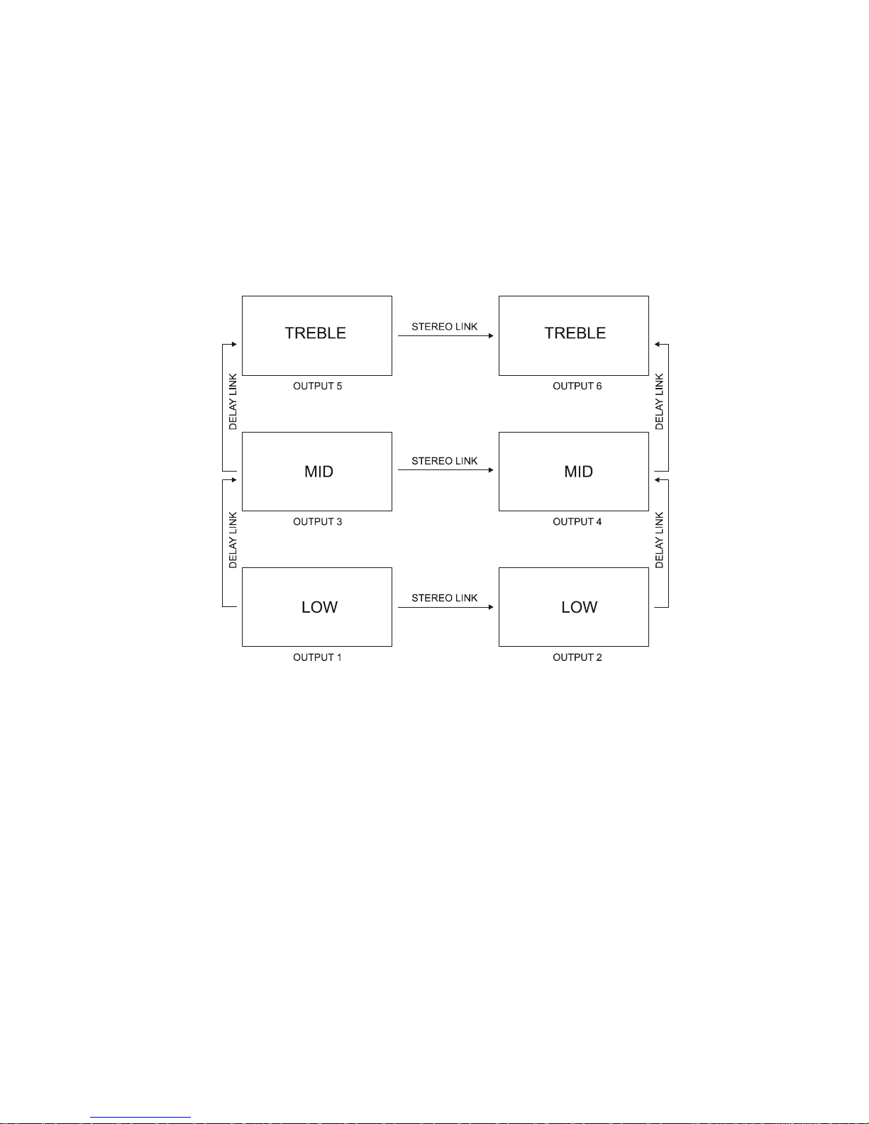
In 2x3-way mode, following channels will be paired:
OUT 1 with OUT 2
OUT 3 with OUT 4
OUT 5 with OUT 6
In 3x2-way mode (LCR), following channels will be paired:
OUT 1 with OUT 2
OUT 4 with OUT 6
OUT 3
OUT 5
STEP and OFFSET functions
In order to define the stereo link parameters either STEP or OFFSET mode must be selected.
• In STEP mode, processor parameters such as filter type, high-pass filter slope, output polarity,
etc. can be linked between channels. If STEP mode is selected, changing a parameter of one
linked channel will cause the value of the same parameter of the pair channel to change
automatically.
• In OFFSET mode, no selection options are offered. Instead, a list of numeric values for
frequency, gain, delay, etc. are presented. When linking two channels, these parameters may be
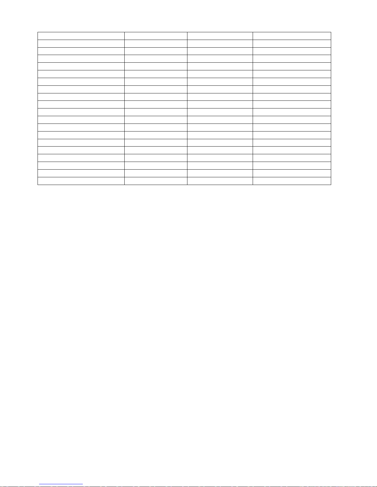
compensated. Following table shows the linking options for all parameters.
Page 11
11
PARAMETER LINK MODE 2X3 WAYS 3X2 WAYS (LCR 2WAY)
Input Delay Offset A(CH1)-B(CH2) A(CH1)-B(CH2)
Input EQ type Step A(CH1)-B(CH2) A(CH1)-B(CH2)
Input EQ frequency Offset A(CH1)-B(CH2) A(CH1)-B(CH2)
Input EQ gain (+/-) Offset A(CH1)-B(CH2) A(CH1)-B(CH2)
Output Name Offset 1-2, 3-4, 5-6 1-3, 4-6
Output Source Offset A(1,3&5) & B(2,4&6) A(1&4)/B(2&6)/A+B(3&5)
Output Gain Offset 1-2, 3-4, 5-6 1-3, 4-6
Output Limiter Offset 1-2, 3-4, 5-6 1-3, 4-6
Output Delay Offset 1-3, 3-5, 2-4, 4-6 1-4, 2-5, 3-6
Output Delay link Offset 1-3, 3-5, 2-4, 4-6 1-4, 2-5, 3-6
Output Polarity Step 1-2, 3-4, 5-6 1-3, 4-6
Output bass curve Step 1-2, 3-4, 5-6 1-3, 4-6
Output bass frequency Offset 1-2, 3-4, 5-6 1-3, 4-6
Output treble curve Step 1-2, 3-4, 5-6 1-3, 4-6
Output treble frequency Offset 1-2, 3-4, 5-6 1-3, 4-6
Output EQ type Step 1-2, 3-4, 5-6 1-3, 4-6
Output EQ frequency Offset 1-2, 3-4, 5-6 1-3, 4-6
Output EQ gain (+/-) Offset 1-2, 3-4, 5-6 1-3, 4-6
Output EQ width Offset 1-2, 3-4, 5-6 1-3, 4-6
MONO mode
In mono mode, the processor is configured as follows:
- All outputs (1-6) are connected to input CH1 (A).
- Crossover frequencies are set up to cover the entire audio frequency range. (Full range
operation).
- The default Delay link is set to OFF.
- No stereo linking is allowed.
- The names of the outputs are set to “Band 1” to “Band 6” for Outputs “OUT 1” to “OUT6”
respectively.
Page 12
12
2 x 3 way Mode
In this mode, 2 channels and 3 ways, the processor is configured as follows:
- Outputs 1, 3 and 5 are connected to input channel CH1 (A).
- Outputs 2, 4 and 6 are connected to input channel CH2 (B).
- The default Delay link is set to OFF.
- The stereo link is activated (ON).
- The names assigned to each output are:
OUT 1 and OUT 2 – Low (Bass)
OUT 3 and OUT 4 – Mid
OUT 5 and OUT 6 – High (Treble)
3 x 2 way Mode (LCR 2 way)
In LCR 2 way mode (Left, Centre, Right), the processor is configured as follows:
- Outputs 1 and 4 are connected to input channel CH1 (A).
- Outputs 3 and 6 are connected to input channel CH2 (B).
- Outputs 2 and 5 are connected to input SUM CH1(A)+CH2(B).
- The default Delay link is set to OFF.
- The stereo link is activated (ON).
- The names assigned to each output are:
OUT 1 and OUT 3 – Low (Bass)
OUT 2 – C Low (Centre Bass)
OUT 4 and OUT 6 – High (Treble)
OUT 5 – C High (Centre Treble)
Page 13
13
Once the basic operation mode has been chosen, all relevant processor parameters can be modified in
order to match the desired specifications.
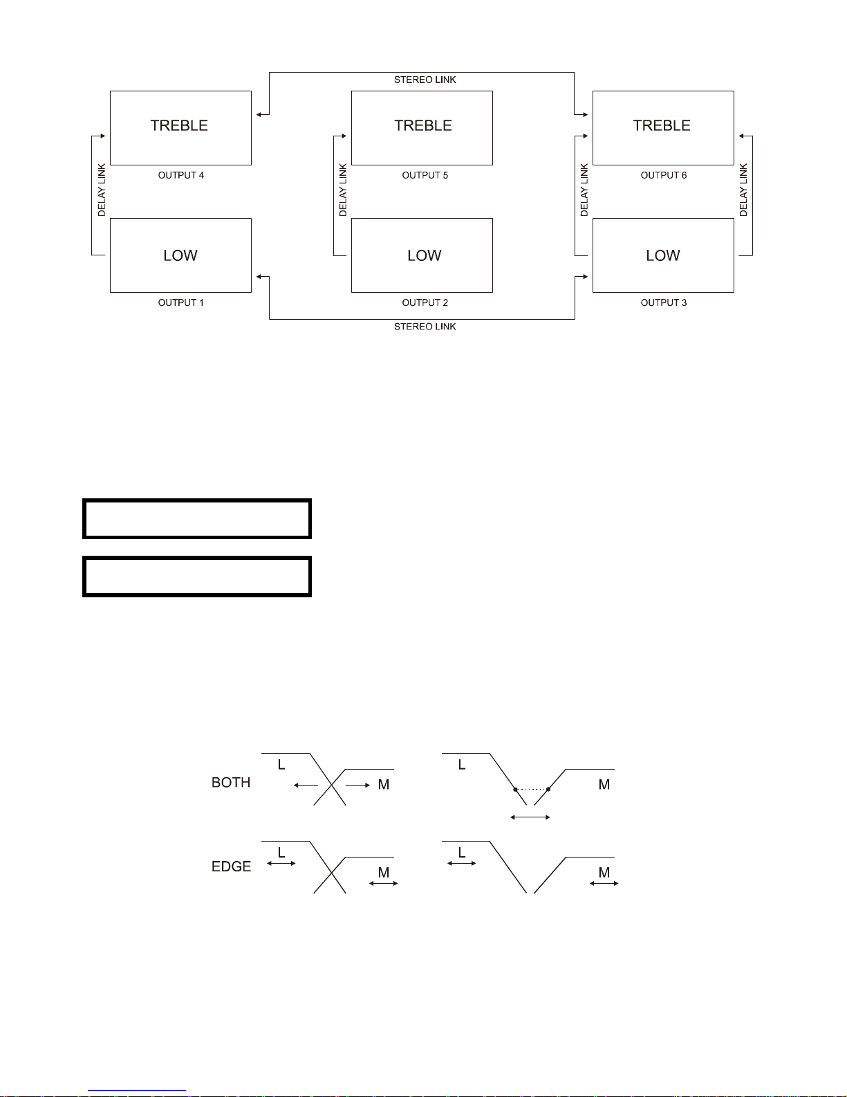
2. Crossover operation modes (Xover mode)
From this screen, the way in which the crossover filters of each output are modified can be configured.
Two operation modes are available: BOTH and EDGE.
SETUP
Xover Mode Both
or
SETUP
Xover Mode Edge
If BOTH mode is chosen, modifying e.g. the upper cut-off frequency of the bass channel will drag the
lower cut-off frequency of the neighbouring filter, i.e. the mid filter. This crossover frequency needs not
be the same for both filters, as a certain “offset” can be put in between them. When e.g. the upper filter
slope of one channel configured as LOW way is changed in BOTH mode, the lower filter slope of the
adjacent channel configured as MID way is changed, too.
In EDGE mode, all crossover frequencies and slopes may be adjusted independently, without one way
affecting the adjacent one.
Page 14
14
3. Adjusting the delay measurement units
From this screen, the measurement units for the delay parameter can be chosen to suit the application.
The delay parameter can be adjusted in the range from 0 to 635 ms in steps of 21µs.
SETUP
Delay Units ms
Following units are available:
- Milliseconds (ms)
- Metres (m)
- Feet (ft)
- Frames (24, 25 or 30 frames per second)
To chose one or another measurement unit, use the ? and ? keys or the encoder wheel.
4. LCD Display contrast adjustment
This screen allows changing the contrast of the LCD display.
SETUP
Contrast /
Chose the preferred setting using the encoder wheel or the ? and ? keys
5. Safety lock
The DP300 offers 3 levels of safety locking designed to protect the system, the programs and the
parameters stored in the processor from unwanted or accidental manipulation. These levels are called
“Lock Out”, “Owner Lock” and “OEM Lock”.
- Lock Out
This is the first locking screen that appears, being the most basic locking level of all three.
SETUP
Lock Out Off
Lock Out can be set to “Off” (deactivated) or “On” (activated). If it’s set to “On”, following parameters
and functions are affected:
- No parameter can be modified, except Lock Out and Display contrast.
- The “Mute” pushbuttons are disabled.
- Programs cannot be stored or recalled.
In order to unlock the unit again, simply access the Lock Out menu item and set it to “Off”.
Page 15
15
- OEM Lock
Attention! Keep your password in a save location. The unit cannot be unlocked without this
password.
The OEM Lock level lets you lock all or some edited parameters in a program. The locking information
will be saved to the program itself.
Following screen appears:
SETUP
OEM Lock Off
If the ? key is pressed or the encoder wheel is turned right, a new screen appears asking for a
password.
OEM PASSWORD
-
The password should be introduced using the PREVIOUS and NEXT keys or the encoder wheel to
chose the character and the ? and ? keys to move the cursor left or right. The default password for the
DP300 is ECLER. If a wrong password is entered, an error message appears, and the initial OEM Lock
screen will reappear.
WARNING!
Password wrong
Once the password is introduced, press ENTER to confirm. Following message will appear briefly:
Lock Setup OEM
Enter when done
Then, the processor takes you to the “Lock all” screen automatically.
Lock Setup OEM
Lock all? No
Once in “Lock All” mode, all processor parameters can be locked, so that later, individual parameters
can be unlocked selectively. In order to lock all parameters, turn the encoder wheel or press the
? and ? keys so that “Yes” appears. At this point, the processor will ask for the new password. You
can enter the same or a different one.
In case a previous locking needs to be unlocked, select “Yes” first and then “No”.
In order not to execute this action, press SAVE/ENTER.
Once the program is locked, a rhombus appears at the lower right corner of the display, indicating the
Locked status.
Page 16
16
“Lock Setup” mode
At this point, if either PREVIOUS or NEXT keys are pressed, the processor enters “Lock Setup” mode.
This mode gives access to all input and output configuration screens, with following limitations:
- The parameter values cannot be altered.
- The SAVE and RECALL menus cannot be accessed.
- Only the SETUP and Stereo Link parameters can be locked.
- Each parameter must be locked or unlocked individually, no matter if the stereo link is activated
or not.
If a certain parameter is unlocked, a screen with its name, value and input or output correspondence is
shown. If now the ? key is pressed or the encoder wheel is turned clockwise, the locking status will
change and a tick appears as a sign that this alteration has been made. You should select all
parameters that must be locked and check that the tick is placed next to each one.
In case all parameters are locked (“Lock All”) you can now unlock specific parameters in the same way.
For example, following screen appears:
IN A OEM
Delay v
All unassigned EQ blocks will not show up in “Lock Setup” mode. This allows that the user cannot
assign additional EQs. If you try to lock a new EQ, following screen appears,
No more Eqs own
Lock unused? v
So that you can choose whether the end user can or cannot add new EQ blocks.
Confirming the locking selection
Once all parameters that need to be locked have been ticked, the selection must be confirmed by
pressing the SAVE/ENTER key. At this point, the screen asking for the password is presented again.
The password must be entered as explained above, pressing ENTER at the end. Once accepted, the
DP300 will return to the SETUP menu.
The DP300 is now locked, although no symbol appears indicating this status. Only the unlocked
parameters can be accessed, while the locked ones do not even be displayed. If an unlocked parameter
of a locked program is changed, the adjustments must be stored to a new program. If the same program
location must be retained, you should first delete the program that occupies that memory location with
the “Delete Prog” function of the SETUP menu.
Page 17
17
Owner Lock
Attention! Keep your password in a save location. The unit cannot be unlocked without this
password.
The “Owner Lock” locking mode is the second security level of the DP300 and operates in exactly the
same way as the “OEM Lock” mode, except the term Own is used instead of OEM and a different
locking symbol is shown. Both locking levels may be used simultaneously. The default password for
“Owner Lock” in the DP300 is USER.
6. MIDI Operation
The DP300 is specified to use MIDI commands. Several screens allow the adjustment of the MIDI
parameters to best suit your system set-up.
Besides this MIDI communication, the DP300 features a RS-323 port for serial connection to a PC. With
the dp:lab editing and control software provided with the processor, all adjustments and program
management can be easily performed remotely from the PC.
Choosing the MIDI Channel (1-16)
From this screen, the channel used to transmit and receive MIDI commands to and from a remote
device can be chosen. Select one channel between 1 and 16 by turning the encoder wheel or pressing
the ? and ? keys.
Keep in mind that for a correct MIDI communication, both receiving and transmitting devices must be set
ot the same MIDI channel.
SETUP
Midi channel 1
Adjusting the MIDI mode
From this screen you can chose which type of information the DP300 can transmit via its MIDI OUT
socket. This will depend on the usage of the DP300 inside your system. Following MIDI modes are
available:
- Off
- Program (Prog)
- Thru
- Master
- PCPort
Off
No type of MIDI messages are transmitted to the OUT port except “MIDI Sysex” (system exclusive)
messages.
SETUP
Midi Mode Off
Page 18
18
Program (Prog)
Allows the transmission of “Program Change” MIDI messages
SETUP
Midi Mode Prog
Thru
The MIDI signal received at the MIDI IN port is replicated and transmitted to the MIDI OUT port.
SETUP
Midi Mode Thru
Master
Allows the transmission of all parameter changes to another unit with the same MIDI channel. This
option is useful if two DP300 processors should operate in parallel with the same settings for stereo
applications.
SETUP
Midi Mode Master
PC Port
Allows the use of the RS-232 port of the DP300 for serial communication with a PC with the dp:lab
software (included with the DP300). This mode also permits the DP300 to be included in MIDI set-ups,
do system exclusive dumps and control other DP300 units.
SETUP
Midi Mode PCPort
MIDI System Exclusive information Dump
From this screen, information stored in the DP300 can be transmitted via a SysEx Dump to other DP300
units or to computer sequencers or software supporting this type of MIDI messages. Connect a MIDI
cable between the MIDI OUT of the transmitting device and the MIDI IN of the receiving device.
Following screen appears first:
SETUP
Midi Dump No
If the ? key is pressed or the encoder wheel is turned right, following screen shows up:
Midi Dump?
Enter to confirm
Page 19
19
At this point, a MIDI SysEx message is sent and the receiving device knows that a MIDI SysEx Dump is
about to be transmitted. The receiving device will show a message informing about that fact.
If the memory of the receiving device should not be overwritten, the ? key must be pressed, so that the
“Allow Dump” setting is changed to “No”. The receiving device will go back to normal operation and
ignore incoming information.
To abandon the MIDI Dump mode, press either PREVIOUS or NEXT keys.
Pressing the SAVE/ENTER key on the transmitting device starts the SysEx transmission process and
following screen appears,
Midi Dump?
Preparing…
Shortly after, the same screen with an ascending percentage counter informs about the progress. At
100% all information has been sent.
Midi Dump?
XX%
Keep in mind that MIDI SysEx Dumps may alter or damage memory contents of different or
incompatible receiving devices. When executing the SysEx Dump, ensure that the different or
incompatible devices are switched off or are set to a different MIDI channel in order to avoid damage to
their memories.
7. Deleting programs
From this screen, programs stored in the processor can be deleted. The first screen shows:
SETUP
Delete Prog No
Pressing the ? key or turning the encoder wheel right enters the Delete Program mode and following
screen appears,
Enter to Delete
6DIGITAL6
where you can chose the program to be deleted by turning the encoder wheel or pressing the ? and ?
keys. Once the program has been found, press SAVE/ENTER to delete the program. Keep in mind that
the locked programs must be first unlocked before they can be deleted.
Page 20
20
7. INPUTS
The DP300 features two physical inputs A (CH1), B (CH2) and the mix of both channels SUM A+B.
Depending on the selected operation mode, the inputs are grouped in different configurations.
In mono mode, they operate independently,
IN A(CH1)
IN B(CH2)
IN A + IN B
In both 2x3 way mode (2 channels, 3 ways) and in LCR 2 way mode (3x2 ways), following grouping is
valid:
IN A & IN B
IN SUM A+B
If the stereo link option should not be used (Stereo Link = Off) the inputs can be set up independently,
without being grouped.
For the inputs A(CH1) and B(CH2), Equalization (Eq) and Delay parameters can be adjusted, but for the
SUM A+B input, only Delay parameters can be modified.
You can switch from one input to the next by pressing the encoder wheel.
In any of the input configuration screens, parameters can be altered by turning the encoder wheel or by
pressing the ? and ? keys. To access the following parameter inside the current input configuration,
press NEXT or PREVIOUS.
Delay
The first configurable parameter for inputs A (CH1) and B (CH2) is the delay amount, which can be
adjusted up to a maximum of 635ms.
IN A
Delay 0.000ms
Equalization (Eq)
One or several equalizer blocks can be assigned to each input A (CH1) and B (CH2). Either Low or high
frequency shelving filters with 6 or 12 dB/oct slopes or fully parametric bell-type filters can be used. In
order to assign these EQ blocks, several parameters which determine the filter characteristics must be
adjusted first.
Following parameters appear on successive presses of the PREVIOUS key:
1. Equalizer type
2. Equalizer frequency
3. Equalizer gain
4. Equalizer width
1. Equalizer type
Pressing the PREVIOUS key brings up the first equalizer configuration screen. This screen refers to the
filter type selection:
IN A & IN B
Eq1S Bel Sp8
Page 21
21
In the previous example screen, the “S” in the Eq1S string indicates that this channel is stereo linked,
meaning that the parameter values changed here affect the other channel as well. If a mono channel is
being configured, the screen looks as follows:
IN A
Eq1 Bel Sp8
As can be seen, the string has been replaced with Eq1, and no “S” appears.
Following filter types can be selected:
Bell
Lo12 – Low Shelf, 12 dB/oct
Lo6 – Low Shelf, 6 dB/oct
Hi12 – High Shelf, 12 dB/oct
Hi6 – High Shelf, 6 dB/oct
The upper left corner of the display shows the input to which the current EQ is being applied. In this
case, input IN A (CH1) is affected.
The Sp indication informs about the number of DSP filters still available. If Sp0 is shown, no more filters
can be applied, as the DSP resources are used up.
2. Equalizer frequency
The equalizer frequency is situated in the centre of the equalizer curve. It’s the so-called “resonant
frequency”. The frequency can be adjusted from 15 Hz to 16 kHz in steps of approximately 1/6 octave.
IN A
Eq1 Fq 1.00kHz
The frequency can be moved by turning the encoder wheel or by using the ? and ? keys.
3. Equalizer Gain
Any equalization applied to an input should have either a positive or a negative gain setting.
IN A
Eq 1 + - +15.0dB
This gain can be adjusted from –15 to +15dB by turning the encoder wheel or by using the ? and ?
keys. If no gain is applied, that equalizer block is not activated. The moment a gain value is given, that
EQ block, e.g. Eq1, becomes active and the parameters of the next EQ block on that input channel, in
this case Eq2, become accessible.
As more EQ blocks are added, the DSP resources are reduced and the Sp indication counts down. The
exact number of available filters may vary depending on certain usage restrictions and the employed
assignments.
To know these restrictions, please refer to the “DSP resources” section of this manual.
Page 22

22
4. Equalizer width
The Wd parameter sets the filter bandwidth for the bell-type filters. It is only available for this type of
equalizer.
IN A
Eq1 Wd 0.300ct
The filter width can be adjusted from 0.05 octaves to 3 octaves in 0.05 octave steps.
The Width setting establishes the filter amount around the centre frequency. The smaller the Wd value,
the narrower the filter bell shape, so that a certain frequency can be affected more selectively. As the
Wd value is increased, the bell shape widens and a smoother filter response is obtained which affects
the adjacent frequencies increasingly.
It’s usual to employ values around Wd=0.3 (1/3 octave)
At this point, a first equalization for this input has been created.
If the current channel has more than one active equalizers, pressing the PREVIOUS button brings you
to initial screen (equalizer type) of the second equalizer. This repeats successively until all input
equalization blocks have passed.
Page 23
23
8. OUTPUTS
The DP300 has 6 outputs (OUTPUT 1-6), which are differently grouped depending on the operating
mode that has been chosen.
In Mono mode, all 6 outputs operate independently.
In 2 x 3 way mode (2 channels, 3 ways), outputs can be linked together. For that reason, they are
grouped as follows:
Output 1 and 2 (OUT1 &OUT2)
Output 3 and 4 (OUT3 &OUT4)
Output 5 and 6 (OUT5 &OUT6)
In 3 x 2 way mode (Left Centre Right, 2 ways) outputs are grouped as follows:
Output 1 and 3 (OUT1 & OUT3)
Output 2 (OUT2)
Output 4 and 6 (OUT4 & OUT6)
Output 5 (OUT5)
If stereo linking is not desired, set the “Stereo Link” option to Off, so that the parameters of each
channel can be modified independently.
When the outputs are linked together, modifying a certain parameter of one channel automatically
updates the same parameter on the linked channel.
To access the parameters of each output, press the encoder wheel. Once in the screen corresponding
to the output to be configured, NEXT and PREVIOUS brings you to the individual parameters of this
output.
Once the desired parameter has been reached, its value can be modified by turning the encoder wheel
or by using the ? and ? keys.
Each one of the outputs offers following configuration options:
1. Output name.
2. Signal Source.
3. Gain.
4. Limiter.
5. Delay.
6. Delay Link.
7. Polarity.
8. Lower filter slope shape (Lo shape).
9. Lower cut-off frequency (Hi pass).
10. Upper filter slope shape (Hi shape).
11. Upper cut-off frequency (Lo pass).
12. Equalizer.
1. Output Name
Depending on the operation mode, each output is assigned a default name. In general, the outputs 1 to
6 are named Band 1 to Band 6 respectively.
OUT 1&3 Band 1
Name Band 1
Page 24
24
If the name should be changed, the DP300 features a collection of pre-programmed names which can
be assigned to any output, depending on its use in the sound system.
Band 1-6
L Low, L Mid, L High
R Low, R Mid, R High
C Low, C Mid, C High
Subs, Low, Lo Mid, Mid, Hi Mid, High
Mid+High
2"Horn, 1"Horn
Bullet
Flat
Unused
Bar, BStage
Delay
Centre
Mono
Aux
10", 12", 15", 18", 21", 24"
1.5"Hn
Delay1, Delay2, Delay3, Delay4, Delay5, Delay6
L Subs, C Subs, R Subs
To select the desired name, use the encoder wheel or the ? and ? keys.
2. Signal Source
Each output must have an assigned input, which represents the source signal for all consequent
processing tasks. Each output can have one of following assigned inputs:
Input INA (CH1)
Input INB (CH2)
Input IN SUM A+B
OUT 1 Band 1
Srce IN A
In this example the unit is in Mono mode and the Output 1 (OUT1) has INA (CH1) assigned as its input.
In general, Input A&B should be selected in the modes which allow stereo linking. In Mono mode or in
the stereo modes without linking, inputs can be freely assigned to each output.
Page 25
25
3. Gain
The gain of each output can be adjusted from –15 to +15 dB in 0,2dB steps. The default gain setting for
all outputs is 0dB.
OUT 1 Band 1
Gain 0.0dB
Attention: Please take care that this gain setting, together with other parameters that represent a
signal gain increase, such as input or output equalization with positive gain, could imply an
output level that saturates the power amplifier input. This circumstance could damage the
speakers.
To adjust the gain setting, use the encoder wheel or the ? and ? keys.
4. Limiter
Each output features a limiter which can be adjusted to any value between –10,0dBV to +20 dBV, in
0,2dB steps.
OUT 1 Band 1
Limit 0.4dBV
The accurate adjustment of the limiter can become very important if loudspeaker systems should be
protected against signal clipping or excessive power.
When a power amplifier receives an input level higher than its nominal input level, the input stage can
get saturated, resulting in an amplified clipped output signal. This clipped signal has a strong DC voltage
component, which can easily damage the loudspeakers. To avoid this, the limiter should be adjusted so
that the saturation of the amplifier input is avoided.
On the other hand, if the power amplifier has a lager power output than the loudspeakers can handle, or
the system must operate during long periods at full power, the limiter must be adjusted so that the signal
delivered by the power amplifier does not damage the speakers.
The limiter threshold level also serves as the reference for the output VU-meter, so that the levels
displayed always stay in relation to the adjusted limiter threshold. If e.g the limiter is set to 2,0dBV, the
LIMIT indication on the output VU-meter corresponds to +2dBV, and the values below are:
VU-meter OUTPUT LEVEL
Limit +2dBV
-3dB -1dB
-6dB -4dB
-12dB -8dB
-20dB -18dB
To adjust the Limit threshold, use the encoder wheel or the ? and ? keys.
Page 26
26
5. Delay
The delay of each output can be adjusted between 0 and 635ms in 0,021ms steps.
OUT 1 Band 1
Delay 0.000ms
The delay units shown on the right of the display (milliseconds in this case) depend on the "Delay
measurement units adjustment" in the SETUP menu.
These units should be chosen to best suit the applications.
To adjust the Delay amount, use the encoder wheel or the ? and ? keys.
6. Delay Link
The Delay Link can be used to keep the same delay offset between channels that have the same delay
amount.
If, e.g. you configure a certain amount of delay to a channel that is stereo linked, the pair channel will
automatically have the same delay assigned.
OUT 1 Band 1
Delay Link Off
Depending on the operating mode, only certain preset delay links can be assigned, as following table
shows:
Mono Mode
Output OUT1 with OUT2
Output OUT2 with OUT3
Output OUT3 with OUT4
Output OUT4 with OUT5
Output OUT5 with None (Off)
2 channel 3 way mode
Output OUT1 with OUT3
Output OUT2 with OUT4
Output OUT3 with OUT5
Output OUT4 with OUT6
Output OUT5 with None (Off)
Output OUT6 with None (Off)
3 channel 2 way mode (LCR)
Output OUT1 with OUT4
Output OUT2 with OUT5
Output OUT3 with OUT6
Output OUT4 with None (Off)
Output OUT5 with None (Off)
Output OUT6 with None (Off)
To change the Delay link setting, use the encoder wheel or the ? and ? keys.
Page 27
27
7. Polarity
The polarity of each output can be set to either "Normal" or "Invert".
OUT 1 Band 1
Polarity Normal
If a certain output is stereo linked, modifying the polarity of one output will also change the polarity of the
paired output.
To change the polarity setting, use the encoder wheel or the ? and ? keys.
8. Lower filter slope shape (Lo shape)
The DP300 offers the possibility to apply band-pass filters to each output. Each filter has a lower and an
upper cut-off frequency, with a specific filter slope shape which determines the filter shape.
Depending on the application, each user can choose the filter type and slope shape which best suits the
particular specifications of the sound system.
In this screen, the lower filter slope shape can be chosen. Following options are available:
Butterworth 6dB/octave (But 6)
Butterworth 12dB/octave (But 12)
Butterworth 18dB/octave (But 18)
Butterworth 24dB/octave (But 24)
Linkwitz-Riley 12dB/octave (L-R 12)
Linkwitz-Riley 24dB/octave (L-R 24)
Linkwitz-Riley 48dB/octave (L-R 48)
Bessel 12dB/octave (Bes 12)
Bessel 24dB/octave (Bes 24)
OUT 1 Band 1
Lo Shape L-R 24
In this example a Linkwitz-Riley filter with a slope of 24dB/oct is applied to OUT 1.
To select the desired filter shape, use the encoder wheel or the ? and ? keys.
9. Lower cut-off frequency (Hi pass)
From this screen, the lower cut-off frequency of the high-pass filter can be adjusted.
OUT 1 Band 1
Hi pass 15.0Hz
Page 28
28
The adjustment range goes from 15Hz to 16kHz, in 1/6 octave steps. If you try to introduce a value
above 16kHz, the text "Off" will appear, while if you try to set i below 15Hz, the text shown is "OUT".
You should consider that if you set the high-pass cut-off frequency above 16kHz, the output of this
channel will be muted, as this frequency is too high.
To adjust the cut-off frequency of the filter, use the encoder wheel or the ? and ? keys.
10. Upper filter slope shape (Hi shape)
From this screen, the upper filter slope shape can be chosen. Following options are available:
Butterworth 6dB/octave (But 6)
Butterworth 12dB/octave (But 12)
Butterworth 18dB/octave (But 18)
Butterworth 24dB/octave (But 24)
Linkwitz-Riley 12dB/octave (L-R 12)
Linkwitz-Riley 24dB/octave (L-R 24)
Linkwitz-Riley 48dB/octave (L-R 48)
Bessel 12dB/octave (Bes 12)
Bessel 24dB/octave (Bes 24)
OUT 1 Band 1
Hi Shape L-R 24
In this example a Linkwitz-Riley filter with a slope of 24dB/oct is applied to OUT1.
To select the desired filter shape, use the encoder wheel or the ? and ? keys.
11. Upper cut-off frequency (Lo pass)
From this screen, the upper cut-off frequency of the low-pass filter can be adjusted.
OUT 1 Band 1
Hi pass 16.0kHz
The adjustment range goes from 15Hz to 16kHz, in 1/6 octave steps. If you try to introduce a value
above 16kHz, the text "OUT" will appear.
To adjust the cut-off frequency of the filter, use the encoder wheel or the ? and ? keys.
Page 29
29
When performing any adjustment to the filter parameters, keep in mind how the "Filter operating mode
(Xover mode)" in the SETUP menu is set. Remember that in BOTH mode, changing one cut-off
frequency will drag the adjacent cut-off frequency. In EDGE mode, modifying one cut-off frequency does
not affect the adjacent band.
If the current output is stereo linked, modifying the filter parameters of one output affects the parameters
of the paired output.
12. Equalizer
One or several equalizer blocks can be assigned to each output. Either Low or high frequency shelving
filters with 6 or 12 dB/oct slopes or fully parametric bell-type filters can be used. In order to assign these
EQ blocks, several parameters which determine the filter characteristics must be adjusted first.
Following parameters appear on successive presses of the PREVIOUS key:
1. Equalizer type
2. Equalizer frequency
3. Equalizer gain
4. Equalizer width
1. Equalizer type
Pressing the PREVIOUS key brings up the first equalizer configuration screen. This screen refers to the
filter type selection:
OUT 1&2 Band 1
Eq1S Bell Sp8
In the previous example screen, the “S” in the Eq1S string indicates that this channel is stereo linked,
meaning that the parameter values changed here affect the other channel as well. If a mono channel is
being configured, the screen looks as follows:
OUT 1 Band 1
Eq1 Bell Sp8
As can be seen, the string has been replaced with Eq1, and no “S” appears.
Following filter types can be selected:
Bell
Lo12 – Low Shelf, 12dB/oct
Lo6 – Low Shelf, 6dB/oct
Hi12 – High Shelf, 12dB/oct
Hi6 – High Shelf, 6dB/oct
The upper left corner of the display shows the input to which the current EQ is being applied. In this
case, output OUT1 is affected.
The Sp indication informs about the number of DSP filters still available. If Sp0 is shown, no more filters
can be applied, as the DSP resources are used up.
Page 30
30
2. Equalizer frequency
The equalizer frequency is located in the centre of the equalizer curve. It’s the so-called “resonant
frequency”. The frequency can be adjusted from 15Hz to 16kHz in steps of approximately 1/6 octave.
OUT 1 Band 1
Eq 1 Fq 1.00kHz
The frequency can be moved by turning the encoder wheel or by using the ? and ? keys.
3. Equalizer Gain
Any equalization applied to an input should have either a positive or a negative gain setting.
OUT 1 Band 1
Eq + - +15.0dB
This gain can be adjusted from –15 to +15 dB by turning the encoder wheel or by using the ? and ?
keys. If no gain is applied, that equalizer block is not activated. The moment a gain value is given, that
EQ block, e.g. Eq1, becomes active and the parameters of the next EQ block on that input channel, in
this case Eq2, become accessible.
As more EQ blocks are added, the DSP resources are reduced and the Sp indication counts down. The
exact number of available filters may vary depending on certain usage restrictions and the employed
assignments.
To know these restrictions, please refer to the “DSP resources” section of this manual.
4. Equalizer width
The Wd parameter sets the filter bandwidth for the bell-type filters. It is only available for this type of
equalizer.
OUT 1 Band 1
Eq 1 Wd 0.300ct
The filter width can be adjusted from 0.05 octaves to 3 octaves in 0.05 octave steps.
The Width setting establishes the filter amount around the centre frequency. The smaller the Wd value,
the narrower the filter bell shape, so that a certain frequency can be affected more selectively. As the
Wd value is increased, the bell shape widens and a smoother filter response is obtained which affects
the adjacent frequencies increasingly.
It’s usual to employ values around Wd=0.3 (1/3 octave)
At this point, a first equalization for this output has been created.
If the current channel has more than one active equalizers, pressing the PREVIOUS button brings you
to the initial screen (equalizer type) of the second equalizer. This repeats successively until all output
equalization blocks have passed.
Page 31

31
DSP Resources
The DP300 employs 2 DSP chips. The equalizers and crossover filters share the resources of both
DSPs, so that certain assignment limitations must be considered, as following table shows:
DSP Total nr.
of filters
Xover
OUT1&2
Xover
OUT3-6
Input Eq Eq
OUT1&2
Eq*
OUT3-6
DSP 1 18 All None All All DSP 2
DSP 2 20 None All None None DSP 1
* The equalizer of the outputs 3 to 6 (OUT3-OUT6) can either be executed by DSP1 or DSP2.
Nevertheless, first all resources of DSP2 are used up before using DSP1.
As a summary, consider following facts:
- DSP1 features 18 filters.
- DSP2 features 20 filters.
- The Xover filters for outputs OUT1&OUT2 are executed by DSP1.
- The Xover filters for outputs OUT3-6 are executed by DSP1.
- All input equalizers are executed by DSP1.
- All output equalizers for outputs OUT1&OUT2 are executed by DSP1.
- The equalizers for output 3-6 are executed by either DSP.
Page 32
32
PROGRAM MANAGEMENT
The DP300 allows 60 different programs to be stored in its internal memory. With the use of the dp:lab
software included with the DP300, programs can be stored in the computer hard drive. Programs can be
stored, recalled, modified, protected, etc. The basic program management functions are:
1. Storing programs
2. Recalling programs
3. Deleting programs
1. Storing programs
The DP300 has a SAVE/ENTER key that allows saving programs to its internal memory. Pressing this
key brings you to following screen:
SAVE
10 ECLER
where 10 is the program number and "ECLER" is the program name. The characters at the cursor
position can be changed by using the PREVIOUS and NEXT keys or the encoder wheel. The cursor can
be moved left and right by pressing the ? and ? keys. The name can be made up of up to 8
characters.
To exit the "SAVE" mode, press the RECALL key.
The program gets stored by pressing the SAVE/ENTER key again. At that point, following screen
appears, asking if the program should be locked.
Store Locked?
Locked
The word "Locked" and the symbol of a key are shown. If the program should be stored and locked,
press the SAVE/ENTER key again. Otherwise, turn the encoder or press the ? key so that the word
"Unlocked" appears, indicating that the program will be stored unlocked.
In case you attempt to store previously locked program, following screen will appear during several
seconds,
Program Locked!
10 ECLER
Indicating that the program is already locked. It can be unlocked by turning the encoder wheel or by
pressing the ? key and saved as explained above.
2. Recalling programs
By pressing the RECALL key, programs stored in the processor internal memory can be recalled. The
first program to appear is always the last one used.
RECALL
10 ECLER
Page 33
33
The program to be recalled must be selected by pressing the PREVIOUS and NEXT keys or by turning
the encoder wheel. A key symbol next to the program name indicates that that program is locked.
By pressing the RECALL key again, the program is recalled from memory.
3. Deleting programs
In order to delete a program, the "Delete Program" screen of the SETUP menu must be accessed.
From this screen, individual programs can be deleted from memory. The first screen to appear is:
SETUP
Delete Prog No
If the ? key is pressed or the encoder wheel is turned right, the Delete Program mode is entered. and
following screen is shown:
Enter to Delete
6DIGITAL6
From here, the program to be deleted can be selected by turning the encoder wheel or by pressing the
? and ? keys. Once the program is selected, press the SAVE/ENTER key to delete it.
Keep in mind that locked programs must be unlocked prior to deletion.
9. PROGRAMMING EXAMPLE
This chapter explains the practical process involved in programming the processor for a standard stereo
3-way system (Bass, Mids, Treble).
Following specifications should be considered:
- Stereo 3-way system.
- Band-pass filter for bass way from 15Hz to 164Hz.
- Band-pass filter for mid frequency way from 164Hz to 1,68kHz.
- High-pass filter for treble way at 1,68kHz.
- All filters should be Linkwitz-Riley type with 24dB/oct slopes.
- The high-pass filter shall include an equalizer at 14,9kHz with +5dB gain.
- Inputs and outputs shall not be delayed.
Start the device and wait until the display stops blinking. Once the processor has booted, the set-up
process can begin.
The first step always consists in specifying the general operation mode. Press the PREVIOUS key to
access the operating mode configuration screen, and select the 2 channel 3 way mode (2 ch 3 way).
SETUP
CONFIG MONO
Turning the encoder wheel right or pressing the ? keys scrolls through all options, letting you change
the default operating mode (MONO) to 2 or 3 ways.
Page 34
34
Chose the 3 way mode and press the ENTER key to confirm the selection.
Change to 3 way?
Enter to confirm
The screen will change according to the new 2 channel 3 way mode.
SETUP
CONFIG 2ch 3 way
In this example, it would be wise to activate the Stereo Link option between channels, although it is not
indispensable. If no stereo linking is specified, all parameters must be configured channel by channel,
otherwise only one of the channel pairs must be set up. In this example it is recommended to activate
the stereo link (Stereo Link = On). Press the NEXT key and following screen appears.
SETUP
Stereo Link ON
Once the operation mode has been selected, let’s now configure the inputs.
Press the encoder to access the Input INA & INB. Press the PREVIOUS and NEXT keys to access the
individual input configuration parameters.
The first screen refers to the delay. Leave this setting at 0,000 ms (no delay)
IN A & IN B
Delay 0.000ms
Next come the screens referring to the input equalizer. Given the circumstance that no input EQ is
needed in this case, these screens will be abandoned to configure the outputs next.
Press the encoder wheel twice gives access to the configuration of the linked outputs OUT1&2. These
two outputs are used to drive the low-frequency way of the speaker system.
Following screen will appear by default.
OUT 1&2 Band 1
Name Band 1
For clarity, it is advisable to change the name of this output pair for clarity to “Low”. Turn the encoder or
use the ? and ? keys to select this name.
OUT 1&2 Low
Name Low
Page 35
35
Now press the PREVIOUS key and the audio source selection will appear. Leave this setting in its
default selection, OUT 1- INA and OUT 2-INB
OUT 1&2 Low
Srce IN a & IN B
Press the PREVIOUS key and the gain screen appears. Leave this setting at 0,0dB gain.
On the following press of the PREVIOUS key, the limiter screen appears. The default value is +4dBV.
Change this value to +0,4 to give a little emphasis to this band without causing too much signal level.
Should you want a stronger limiting, please set up the threshold here. In this example this is not the
case.
As explained in the above paragraphs, pressing PREVIOUS brings you to the configuration of the delay
and delay link parameters. Leave this parameters in their default settings (delay = 0,000ms, Delay Link
= Off).
Next, leave the Polarity setting in Normal position.
At this point, the filter characteristics screens appear consecutively.
The desired filter has a Linkwitz-Riley characteristic with lower and upper cut-off frequencies of 15Hz
and 164Hz.
Press the PREVIOUS key to access the Lo Shape parameter. Chose the “L-R 24” option, i.e. LinkwitzRiley filter with 24 dB/oct slope.
OUT 1&2 Low
Lo Shape L-R 24
Press PREVIOUS again, so that the screen where the lower cut-off frequency can be adjusted, shows
up. Turn the encoder or use the ? and ? keys and adjust 15Hz.
OUT 1&2 Low
Hi pass 15.0Hz
Press the PREVIOUS key to access the Hi Shape parameter. Chose the “L-R 24” option, i.e. LinkwitzRiley filter with 24 dB/oct slope.
OUT 1&2 Low
Hi Shape L-R 24
Page 36
36
Press PREVIOUS again, so that the screen where the upper cut-off frequency can be adjusted, shows
up. Turn the encoder or use the ? and ? keys and adjust 164Hz.
OUT 1&2 Low
Hi pass 164Hz
On the next press of the PREVIUOS key, the screens referring to the equalization appear. As no
equalization should be applied to this band, exit the configuration of the outputs 1 and 2 by pressing the
encoder wheel, giving access to the outputs 3 and 4.
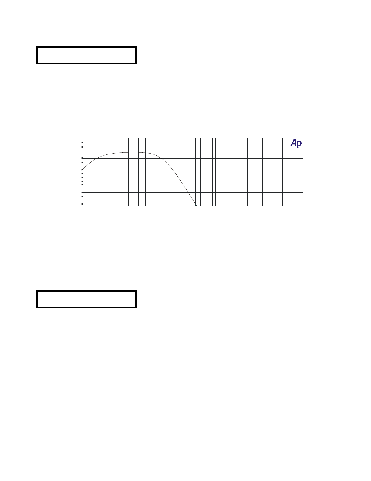
The parameters used to set up the outputs 1 and 2 give place to following frequency response curve,
corresponding to the low frequency way.
Let’s now adjust the parameters of outputs 3 and 4, which are assigned to the mid frequency way in our
system. The adjustment procedure for this output is identical to the previously explained one for outputs
1 and 2. For this reason, the settings common to outputs 1 and 2 are explained more briefly.
In this case, a Linkwitz-Riley filter with 24dB/oct slopes and cut-off frequencies of 164Hz and 1,68kHz
shall be set up.
First, press the NEXT key as necessary until the output renaming screen is reached. Change the output
name to “Mid”, as these outputs will drive the mid-range frequency way.
OUT 3&4 Mid
Name Mid
Press the PREVIOUS key and adjust the audio source, gain, limiter, delay, delay link and polarity as
explained in the set up procedure for outputs 1 and 2.
ECLER S.A.
01/31/05 15:35:31
-40
+10
-35
-30
-25
-20
-15
-10
-5
+0
+5
d
B
r
A
10
20k2050
100
200
5001k2k5k10k
Page 37
37
Press the PREVIOUS key to access the Lo Shape parameter. Chose the “L-R 24” option, i.e. LinkwitzRiley filter with 24 dB/oct slope using the encoder wheel or by pressing the ? and ? keys.
OUT 3&4 Mid
Lo Shape L-R 24
Press PREVIOUS again, so that the screen where the lower cut-off frequency can be adjusted, shows
up. Turn the encoder or use the ? and ? keys and adjust 164Hz.
OUT 3&4 Mid
Hi pass 164Hz
Press the PREVIOUS key to access the Hi Shape parameter. Chose the “L-R 24” option, i.e.
Linkwitz-Riley filter with 24 dB/oct slope using the encoder wheel or by pressing the ? and ? keys.
OUT 3&4 Mid
Hi Shape L-R 24
Press PREVIOUS again, so that the screen where the upper cut-off frequency can be adjusted, shows
up. Turn the encoder or use the ? and ? keys and adjust 1,68kHz.
OUT 3&4 Mid
Hi pass 1.68kHz
On the next press of the PREVIUOS key, the screens referring to the equalization appear. As no
equalization should be applied to this band, exit the configuration of the outputs 3 and 4 by pressing the
encoder wheel, giving access to the outputs 5 and 6.
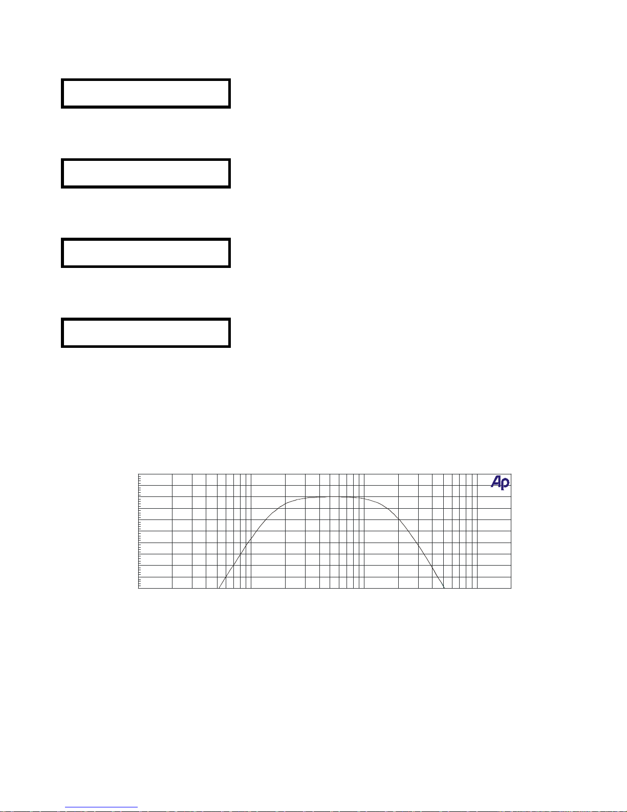
The parameters used to set up the outputs 3 and 4 give place to following frequency response curve,
corresponding to the mid frequency way.
Let’s now adjust the parameters of outputs 5 and 6, which are assigned to the high frequency way in our
system. The adjustment procedure for these outputs is identical to the previously explained one for
outputs 1/2 and 3/4.
ECLER S.A.
01/31/05 15:38:35
-40
+10
-35
-30
-25
-20
-15
-10
-5
+0
+5
d
B
r
A
10 20k20 50 100 200 500 1k 2k 5k 10k
Hz
Page 38
38
In this case, a Linkwitz-Riley high-pass filter with 24dB/oct slopes and cut-off frequency of 1,68kHz shall
be set up.
First, press the NEXT key as necessary until the output renaming screen is reached. Change the output
name to “High”, as these outputs will drive the high frequency way.
OUT 5&6 High
Name High
Press the PREVIOUS key and adjust the audio source, gain, limiter, delay, delay link and polarity as
explained in the set up procedure for outputs 1&2 and 3&4.
Press the PREVIOUS key to access the Lo Shape parameter. Chose the “L-R 24” option, i.e.
Linkwitz-Riley filter with 24dB/oct slope using the encoder wheel or by pressing the ? and ? keys.
OUT 5&6 High
Lo Shape L-R 24
Press PREVIOUS again, so that the screen where the lower cut-off frequency can be adjusted, shows
up. Turn the encoder or use the ? and ? keys and adjust 1,68kHz.
OUT 5&6 High
Hi pass 1.68kHz
Press the PREVIOUS key to access the Hi Shape parameter. Chose the “L-R 24” option, i.e.
Linkwitz-Riley filter with 24dB/oct slope using the encoder wheel or by pressing the ? and ? keys.
OUT 5&6 High
Hi Shape L-R 24
Press PREVIOUS again, so that the screen where the upper cut-off frequency can be adjusted, shows
up. Turn the encoder or use the ? and ? keys and adjust the value OUT. This means that a high-pass
filter with no upper slope is set up.
OUT 5&6 High
Hi pass OUT
On the next press of the PREVIOUS key, the screens referring to the equalization appear. In this case a
boost o 5dB shall be applied at 14,9kHz.
The fist screen to appear is used to select the filter curve type. Choose a bell-type filter.
OUT 5&6 High
Eq1S Bell Sp14
Page 39
39
Press the PREVIOUS key to adjust the centre frequency of the filter.
OUT 5&6 High
Eq1S Fq 14.9kHz
Pressing PREVIOUS again, adjust now the amount of EQ boost. Set it to +5dB.
OUT 5&6 High
Eq1S +- +5dB
The next screen that appears refers to the bandwidth (Wd) of the EQ filter. Leave the value at the
default setting, i.e. 0,3 octaves.
OUT 5&6 High
Eq1S Wd 0.3Oct
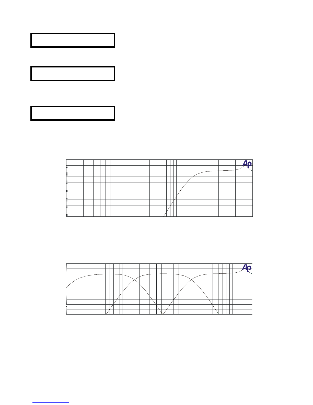
The parameters used to set up the outputs 5 and 6 give place to following frequency response curve,
corresponding to the high frequency way.
Once all three outputs have been configured, the frequency response curve of the DP300 has following
appearance:
After this procedure, a stereo 3 way system with filters for low, mid and high frequencies has been set
up.
ECLER S.A.
01/31/05 15:40:14
-40
+10
-35
-30
-25
-20
-15
-10
-5
+0
+5
d
B
r
A
10 20k20 50 100 200 500 1k 2k 5k 10k
Hz
ECLER S.A.
01/31/05 15:41:52
-40
+10
-35
-30
-25
-20
-15
-10
-5
+0
+5
d
B
r
A
10 20k20 50 100 200 500 1k 2k 5k 10k
Hz
Page 40
40
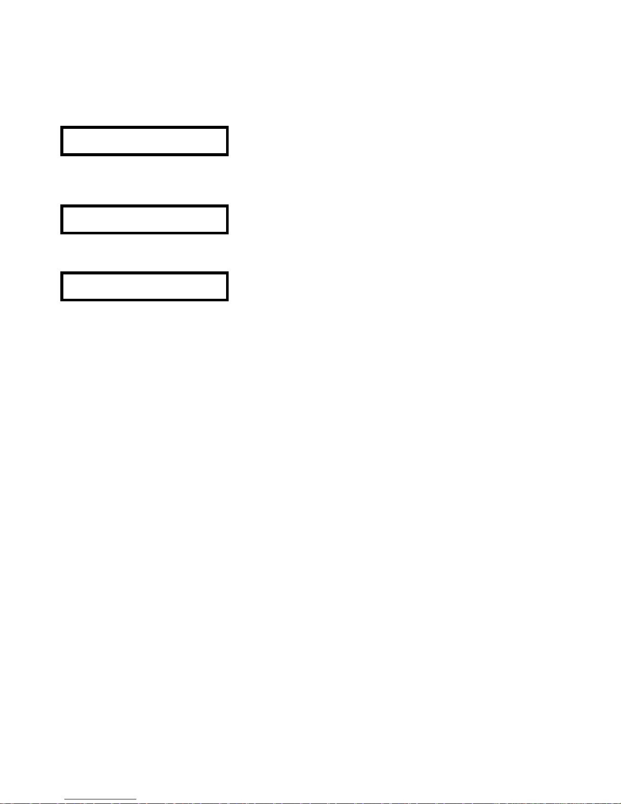
Once all operating parameters have been successfully set up, they should be saved to the DP300
internal memory. Press the SAVE key to enter save mode.
A screen appears asking for the memory location and program name. Use the ? and ? keys to move
the cursor to the desired position (including the characters for the program number) and change the
characters one by one using the encoder wheel or by pressing the PREVIOUS and NEXT keys.
SAVE
1 ECLER
A name with up to 8 characters can be introduced. Press the SAVE key again and a screen appears
asking whether the program should be saved locked or unlocked.
Store Locked?
Locked
Using the encoder wheel or the ? and ? keys, select either “Locked” or “Unlocked”
Store Locked?
Unlocked
Press the SAVE key again to finalize the saving process.
Page 41
41
10. SOFTWARE
dp:lab software
The DP300 processor works together with the dp:lab software which allows
the remote configuration of all device parameters from a standard PC or
laptop with following specifications:
- Intel P3 processor or equivalent at 600 MHz.
- 128 Mbytes of RAM memory.
- Windows 98 SE, Me, XP Home, XP Professional or Windows 2000 operating system.
With the use of this software application, the operating mode, the crossover filters and the input and
output equalizations can be configured in the same aspects as would be done from the unit itself.
The communication between the PC and the DP300 unit is done with a serial RS-232 cable (included
with the DP300).
Attention! In order to achieve a successful communication between the dp:lab software and the DP300,
the “MIDI mode” configuration on the DP300 must be set to “PCPort”, and the selected MIDI channel
should be number 1.
Once the unit has been configured on the PC screen, the program can be directly uploaded to the
DP300 via serial communication.
Installing the dp:lab software
The first step consists in installing the application software on the PC which will serve as programming
platform. For this purpose, the software setup program version 1.32 (V132) is available. Future
improvements or changes may alter this version number.
Page 42
42
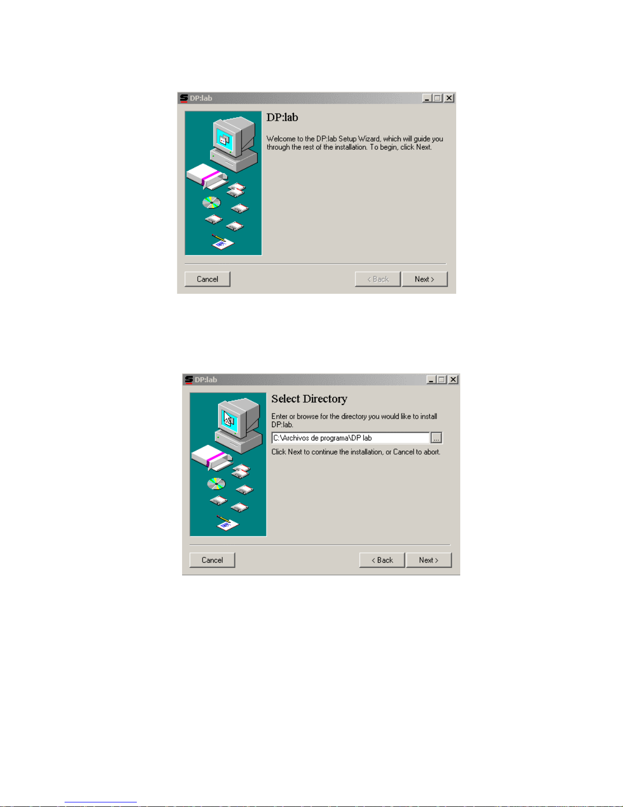
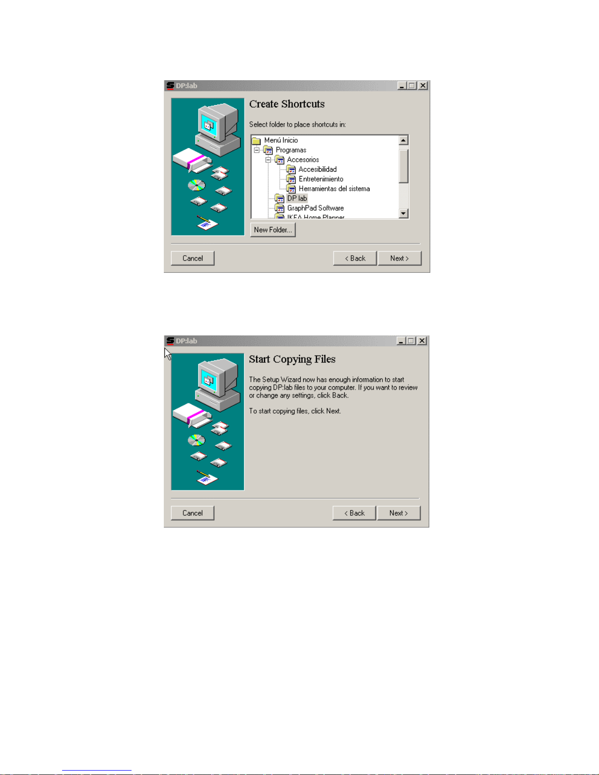
Execute this setup program to start the installation process by double-clicking on the icon.
Following screen welcomes the installation process and invites you to continue.
Click on the Next > button. The following screen now asks you for the application installation directory.
Page 43
43
Once the path has been selected (in case the default path is not used), press the Next > button so that
the next screen appears.
Here, the position of the direct access icon for dp:lab can be chosen. Normally, the default position is a
good choice. Pressing the Next > button again leads you to the following installation screen:
Immediately after the Next > button is clicked on this screen, the copying process will begin.
Page 44
44
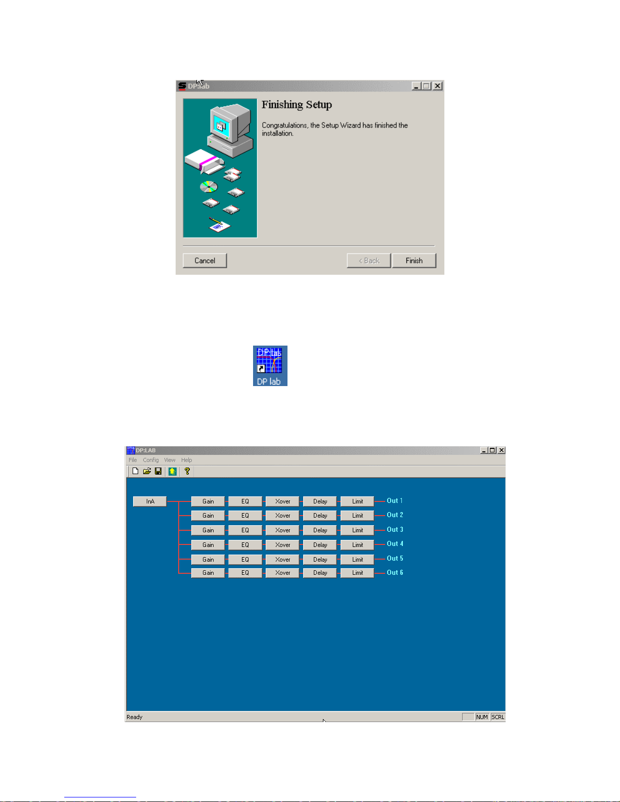
After all files have been copied to the hard drive, the last screen informs about the success of the
installation process.
Press Finish to exit the installation.
Once the software is installed, the desktop will show following shortcut icon.
Double-clicking on this icon executes the application, so that all parameters can be adjusted. Following
main screen appears:
Page 45
45
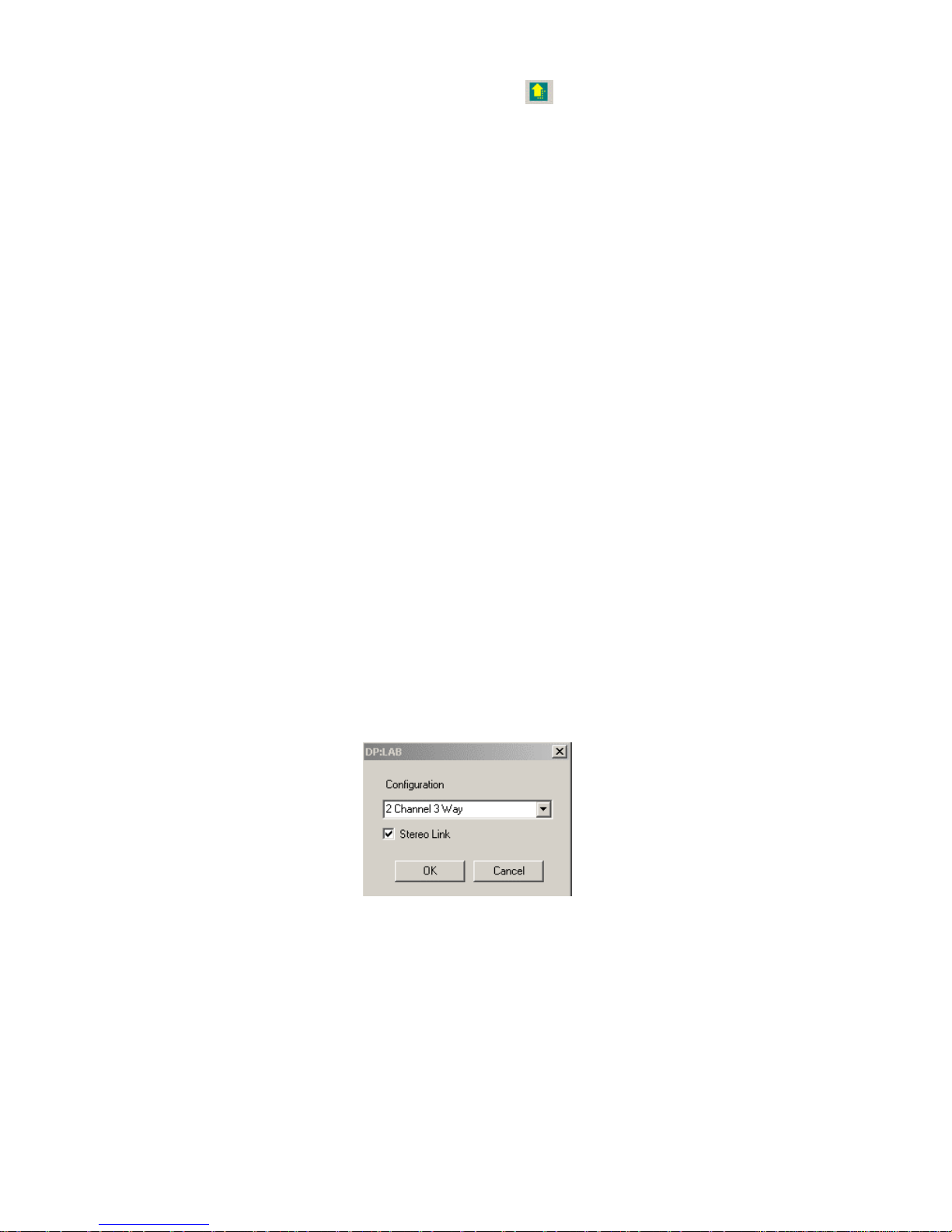
Here, you can directly access the input/output configuration mode and the standard “New File”, “Open
File”, “Save File” and “Help” buttons. An additional button lets you check the serial communication
between the dp:lab and the DP300 and automatically download the current program in the DP300 to the
dp:lab software.
If the communication fails (damaged cable, wrong COM port assignment, wrong MIDI channel) an error
message will appear.
The main screen also gives access to the menus File, Config, View, Help and Exit
The File menu includes following commands:
- New, creates a new file.
- Open, opens an existing file.
- Save, saves the current program.
- Save As, saves the current program wit a different name.
- Exit, leaves the dp:lab application.
The Config Menu has following items:
- Configuration, to selct the desired operation mode (mono, …).
- RS232, to assign the serial communication port.
- Memory, to remotely manage the programs stored in the DP300 and in the PC.
From the View menu, you can show or hide the Toolbar and the Status Bar
The Help Menu informs about the dp:lab software version.
This manual concentrates on the options in the Config menu, which allows remote control of all DP300
parameters.
CONFIG MENU
Configuration
This menu item lets you choose the general operating mode of the DP300. Following screen appears
when this item is selected,
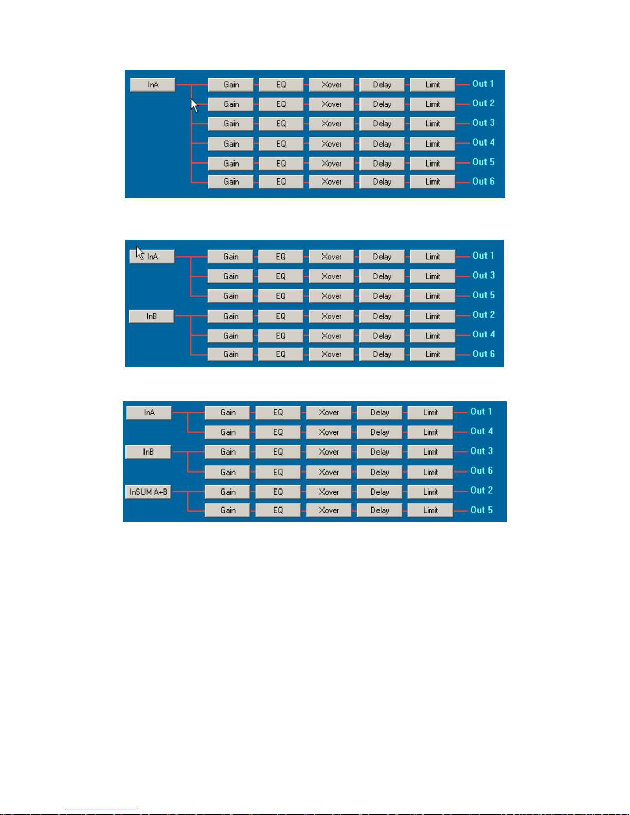
Following modes are available:
Page 46
46
Mono Mode
2 channel 3 way mode
3 channel 2 way mode
In the stereo modes, you can choose wether the Stereo Link should be activated or not. In Mono Mode,
this option is not available.
Page 47
47
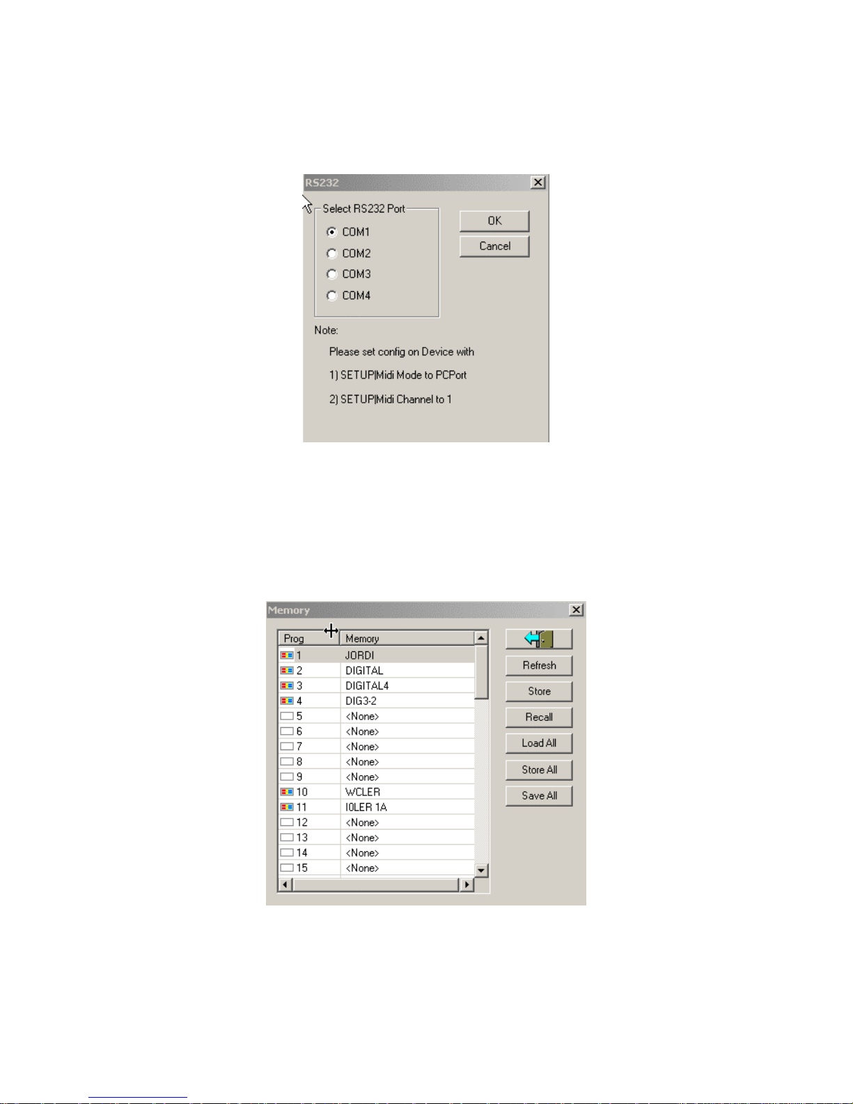
RS232
This options allows you to choose one of the serial communication port (COM1-4) which is used to
establish communication with the DP300. The included serial cable with male/female D-SUB9
connectors should be connected between both devices. This menu item also informs about the required
settings on the DP300 so that a successful communication can be established.
The DP300 should be configured in PCPort MIDI mode and MIDI channel number 1.
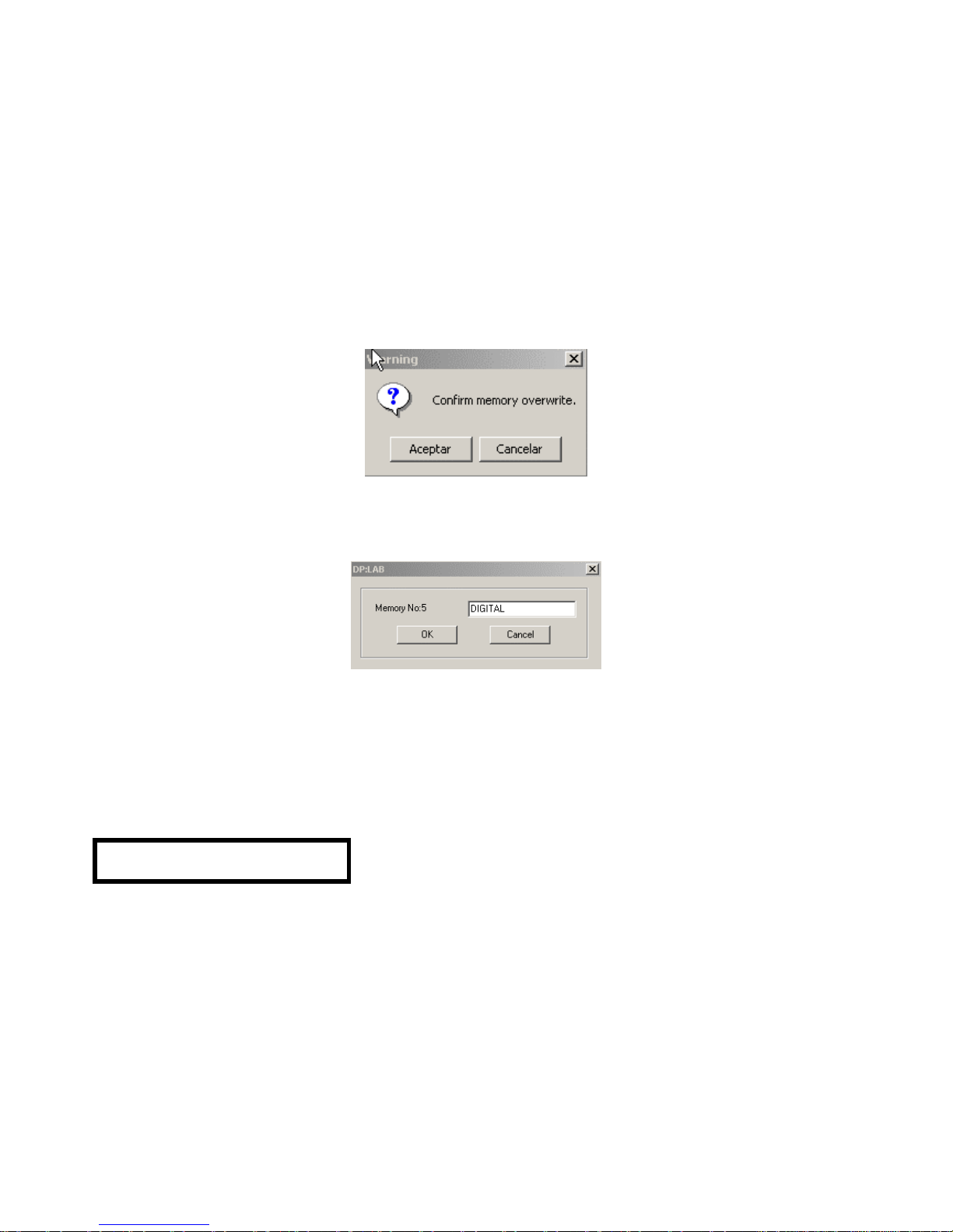
Memory
This menu option allows remote management of the programs stored in the DP300 internal memory,
with the ease of the PC interface.
Page 48
48
This window includes following commands:
Refresh
This command refreshes and displays the all the programs currently stored in the DP300 in the
application window. The programs are displayed in the same order, the same position and name as in
the DP300 itself.
Store
With this command, the currently active set-up in the dp:lab software can be uploaded to the selected
memory location (in the “Memory” window) on the DP300.
Before this action is executed, the software will ask for confirmation before overwriting the DP300
memory position.
Once the action has been confirmed, dp:lab will ask for the program name to be stored on the DP300.
The program will be stored to the currently selected memory location of the “Memory” window.
After clicking OK, the current settings in the dp:lab software will be uploaded and stored to the DP300
Recall
This command executes the same command as the previously explained Recall command in the
DP300. When the dp:lab Recall button is clicked, (e.g. to recall the program DIGITAL in memory
position 2), the DP300 display will show following message,
RECALLING 00
2 DIGITAL
and program 2 DIGITAL will be recalled from memory.
Load All
This command is used to download the entire memory contents of the DP300 to the PC hard drive.
These files have a “name.ay” format and contain the whole memory structure and program contents of
the DP300.
Page 49

49
Store ALL
This command is used to upload all programs to the DP300 at once. Each program retains its memory
position and parameter configuration.
The DP300 will show following message, indicating that an incoming memory dump from the dp:lab is
arriving.
WARNING!
Incoming Dump
Save All
This command is used to save the files in memory to the PC hard drive. These files have a “name.ay”
format and contain the whole memory structure and program contents of the DP300.
Page 50
50
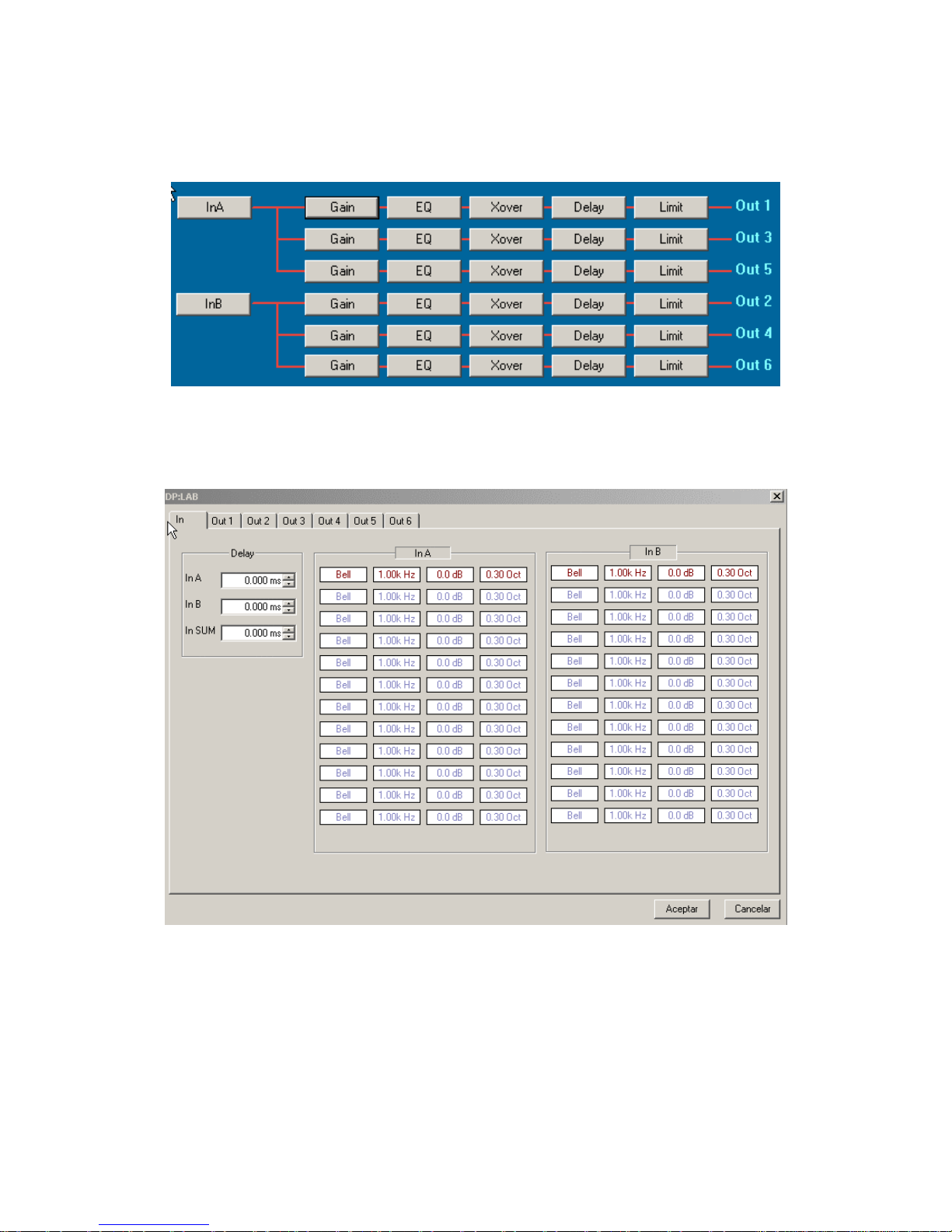
Configuring the filters and the equalizers
All filter and equalizer configuration parameters can be easily adjusted from the dp:lab software for later
uploading to the DP300 unit.
The process is started from the dp:lab main screen:
To access the configuration screen, click on the input or output to be set up and following tabbed screen
appears, giving access to all individual settings of that input or output. Clicking on InA or InB shows
following window:
Clicking on the corresponding tab, access is given to all parameters of that particular input or output.
Page 51
51
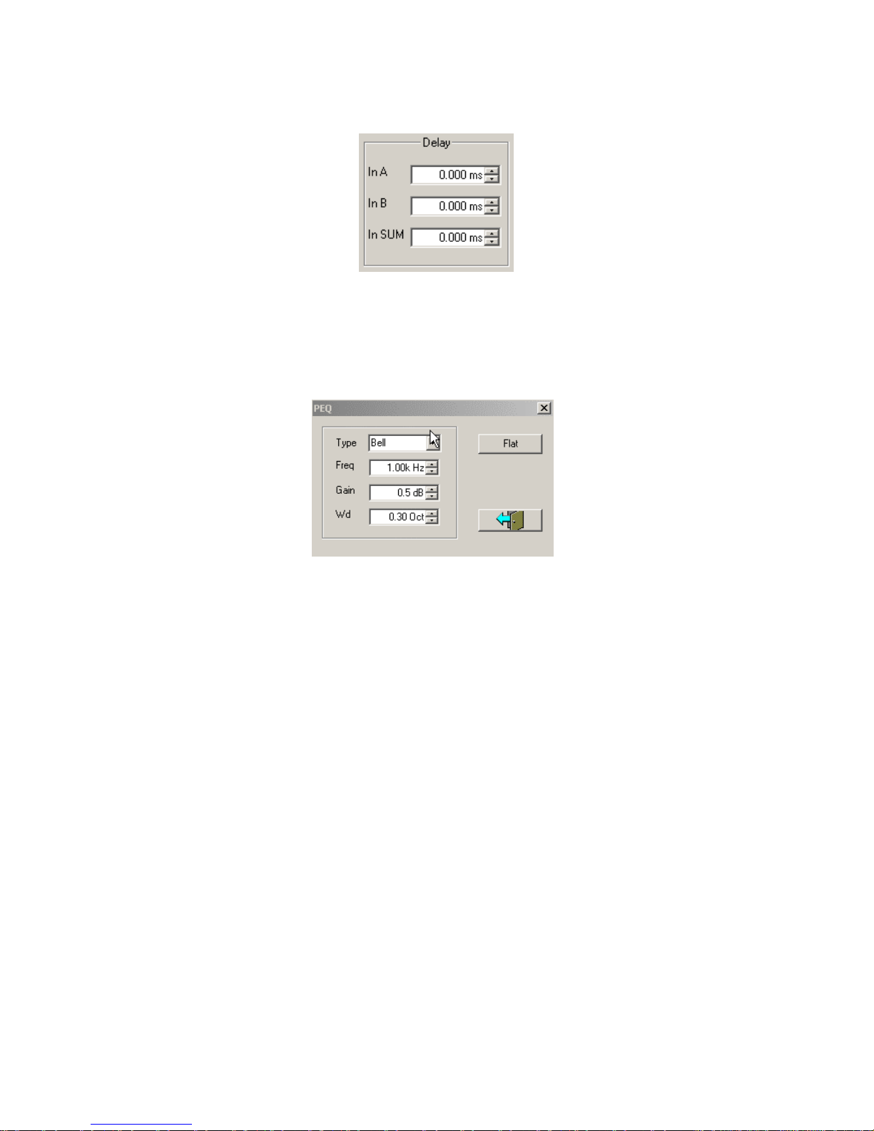
Inputs InA (CH1) and InB (CH2)
For each input, the delay amount and equalizers can be configured:
The value can be modified by clicking on the up and down arrows to increase or decrease the delay
amount.
If one or more equalizers should be included, click with the left mouse button on the desired equalizer
type button. Following EQ adjustment window appears:
From this window, the equalizer type, centre frequency, gain and bandwidth can be adjusted. The
parameters correspond exactly with the previously explained ones in the DP300 unit.
Page 52
52
Outputs
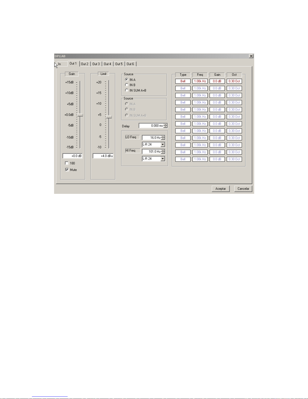
Clicking on an output tab, brings up the output configuration window. Please consider that in stereo link
configurations, outputs will appear as pairs, according to the link options:
From this window, output gain, limiter, source, delay, crossover filters and equalizers can be easily
configured. The meaning of these parameters is exactly the same as previously explained for the DP300
unit.
The crossover filters can be configured in exactly the same way as in the DP300 unit. Filter type
(Butterworth, Bessel, Linkwitz-Riley), filter slope and upper and lower cut-off frequencies can be
adjusted here.
The output equalizers can be set up in the same way as previously explained for the inputs. Always
keep in mind that the DSP imposes a limitation in the number of available filters. Refer to the “DSP
resources” section in this manual for further information.
Page 53
53
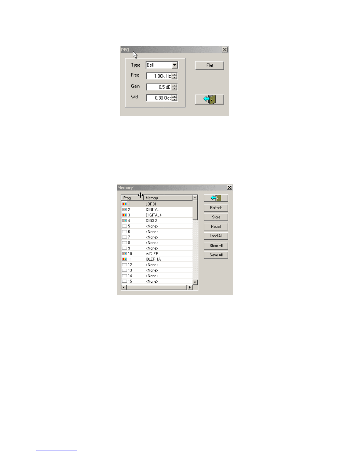
If one or more equalizers should be included, click with the left mouse button on the desired equalizer
type button. Following EQ adjustment window appears:
From this window, the equalizer type, centre frequency, gain and bandwidth can be adjusted. The
parameters correspond exactly with the previously explained ones in the DP300 unit.
Once all parameters have been adjusted, this window can be closed by clicking the “Accept” button.
If the information should be transferred to the DP300, open the Memory window from the Config menu.
Ensure that the PC is correctly connected to the DP300 and that the communication is successful.
Once this window is open, select the memory position to be overwritten and click the Store Button.
Execute the transfer to the DP300 as previously explained.
Once the transfer has ended, the process is finished. You can close the Memory window and optionally
save the current program to the PC hard drive with the Save command in the File Menu. dp:lab can be
closed by clicking on the Exit button.
Page 54

54
Contenido del manual
1. NOTA IMPORTANTE 55
2. INSTALACIÓN 56
3. INTRODUCCIÓN 56
4. PANEL FRONTAL 57
5. PANEL POSTERIOR 59
6. MODO CONFIGURACIÓN (SETUP) 60
7. ENTRADAS 71
8. SALIDAS 74
9. EJEMPLO DE PROGRAMACIÓN 84
10. SOFTWARE 92
11. CARACTERÍSTICAS TÉCNICAS 207
Todos los datos están sujetos a variación debida a tolerancias de producción. ECLER S.A. se reserva el derecho de realizar
cambios o mejoras en la fabricación o diseño que pudieran afectar las especificaciones.
Page 55
55
1. NOTA IMPORTANTE
Enhorabuena. Vd posee el resultado de un cuidado diseño y de una esmerada fabricación.
Agradecemos su confianza por haber elegido nuestro procesador DP300.
Para conseguir la máxima operatividad del aparato y su máximo rendimiento, es MUY
IMPORTANTE antes de su conexión, leer detenidamente y tener presentes las consideraciones que en
este manual se especifican.
Para garantizar el óptimo funcionamiento de este aparato, recomendamos que su
mantenimiento debe ser realizado por nuestros Servicios Técnicos.
Precauciones
Este aparato debe ser conectado a tierra mediante su cable de alimentación.
No exponga el aparato a la caída de agua o salpicaduras, no ponga encima objetos con líquido ni
fuentes de llama desnuda, como velas.
En caso de requerir alguna intervención y/o conexión desconexión del aparato debe
desconectarse previamente de la alimentación.
En el interior del aparato no existen elementos manipulables por el usuario.
Bucles de masa
Procuraremos que las masas mecánicas y eléctricas, chasis y conexiones, que llegan al aparato
sean independientes.
La formación de bucles de masa se detecta por un zumbido de baja frecuencia (50Hz). Estos
zumbidos según nivel pueden llegar a interferir en la calidad de la reproducción sonora.
Conexiones de audio
Normalmente a los cables y conectores no se les presta el interés merecido. En muchas ocasiones
y debido a una mala conexión o por el uso de cables de baja calidad, pueden aparecer importantes
problemas en la reproducción sonora.
Limpieza
El panel de mandos no deberá limpiarse con ninguna sustancia disolvente, abrasiva o derivada del
petróleo, ya que se corre el riesgo de deteriorar la pintura y serigrafía. Para su limpieza emplearemos un
paño ligeramente humedecido en agua y con un poco de jabón líquido. Debe tenerse siempre la
precaución de que no caiga líquido por ninguno de los orificios del aparato. Nunca utilizaremos para
"rascar" la placa de mandos objetos punzantes o erosivos.
Page 56

56
2. INSTALACIÓN
El DP300 puede montarse en un rack standard de 19" (482.6mm) ocupando una unidad rack de
altura (44mm). Se suministran arandelas de plástico para que pueda montarse sin dañarlo.
En instalaciones profesionales se ubicará preferentemente en el mismo rack donde estén
situados los amplificadores de potencia.
Ya que el consumo es muy bajo, no precisa ventilación, sin embargo, debe evitarse que esté
expuesto a una temperatura extrema y debe procurarse que la atmósfera en que esté emplazado sea lo
más seca y limpia de polvo posible.
Es importante no situarlo cerca de fuentes de ruido, tales como transformadores, variadores de
tensión, motores, etc..., así como de los cables de alimentación de estos. Por esta misma razón y bajo
ninguna circunstancia deben quitarse las tapas metálicas del aparato.
El DP300 funciona con tensión alterna de 90 a 264V y 47 a 63Hz. Este aparato equipa una
fuente de alimentación sobredimensionada capaz de adaptarse sin ningún tipo de ajuste a la tensión de
red de cualquier país del mundo.
Aunque el ruido producido por la puesta en funcionamiento es mínimo, siempre resulta muy
recomendable poner en marcha los aparatos siguiendo el recorrido de la señal, fuentes de sonido, unidad
de mezclas, procesador y finalmente amplificadores de potencia. El paro de los aparatos debe realizarse
en la secuencia inversa. Siguiendo este orden los picos o transitorios producidos por el encendido o
apagado de los aparatos no afecta a los siguientes, y por consiguiente tampoco llegan a los altavoces,
elementos extremadamente susceptibles de averiarse en estos casos.
3. INTRODUCCIÓN
PROCESADOR DIGITAL PARA SISTEMAS DE ALTAVOCES DP300
La solución definitiva para realizar un ajuste y control exhaustivo de complejos sistemas de
sonido profesional mediante el software específico Ecler dp:lab. Excelente calidad de sonido y amplia
dinámica. El DP300 utiliza convertidores tipo S-? AD/DA de alta calidad, 48kHz de frecuencia de
muestreo y un DSP de 2x24 bit.
Características principales
• Alta calidad de sonido gracias a su procesador DSP de 24 bits y “sampling rate” de 48kHz.
• Dispone de 2 entradas y 6 salidas. Posibilidad de funcionar en modo Mono, 2x3 vías o 3x2 vías.
• Pendientes del crossover seleccionables entre 6, 12, 18, 24 o 48dB por octava así como el tipo
de filtro: Butterworth, Linkwitz-Riley o Bessel.
• Ecualización tipo paramétrico o shelving equalization para conseguir una suave respuesta en
frecuencia de hasta 38 bandas.
• Ajuste digital de las ganancias de –15dB a +15dB.
• Limitador compresor. Nivel umbral del compressor de salida ajustable.
• Posibilidad de invertir la polaridad en cada salida.
• Entradas y salidas electrónicamente balanceadas.
• Hasta 635ms de delay de señal por vía.
• Posibilidad de almacenar hasta 60 programaciones de usuario diferentes en cada unidad
DP300. Mediante el software de control dp:lab (suministrado con el DP300), se podrán
almacenar tantas configuraciones como quepan en el disco duro del sistema.
• Sistema de 3 niveles de bloqueo y 2 de protección de datos con contraseña.
• Display Backlit LCD en azul de 2x16 caracteres.
• Control vía MIDI y RS-232.
• Software de control y programación dp:lab para la configuración y programación de los
parámetros de la unidad DP300.
Page 57
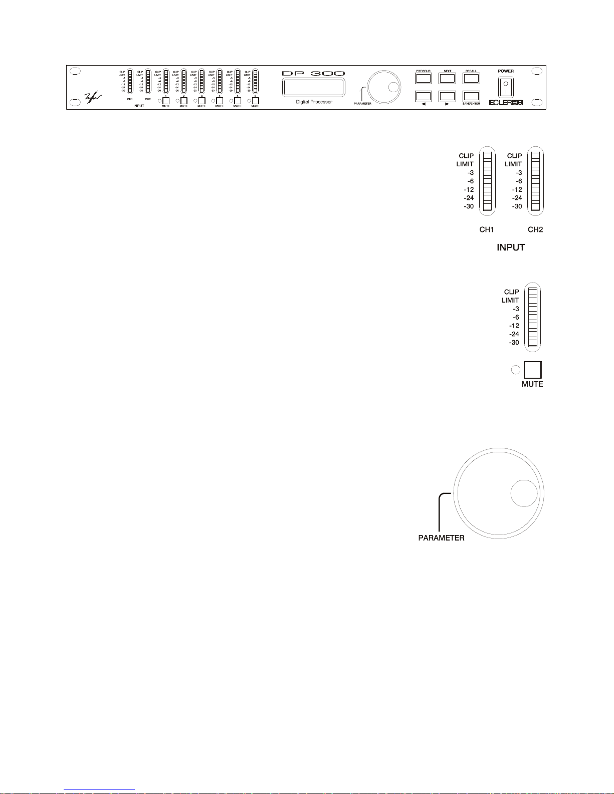
57
4. PANEL FRONTAL
Vúmetro de entrada
El vúmetro de entrada permite visualizar el nivel de la señal de entrada con
indicación de -30dB, -24dB, -12dB, -6dB y -3dB. Dispone además de indicador de
LIMIT y de CLIP. Además de funcionar como monitor de nivel de entrada, nos
informa en caso de producirse el clip de la señal digital. Si el led de CLIP se
enciende pero el inmediatamente inferior no lo hace, significa que el circuito que
está en clip es el digital (DSP), y no el circuito analógico de entrada. Esto puede
producirse si se realizan ecualizaciones erróneas o aplican ganancias excesivas a
alguna de las salidas.
Vúmetro de salida
El vúmetro de salida permite visualizar el nivel de salida relativo al ajuste del umbral
de disparo “threshold”. Si se envía, por ejemplo, una señal de +4dB a una salida ajustada a
un nivel de umbral de disparo de 0dB, el led que se encenderá será el de -6dB.
Botones de MUTE
Estos botones (uno para cada una de las salidas) permiten silenciar la salida
seleccionada mediante su pulsación. Cuando la salida esté silenciada, se encenderá el LED asociado a
cada uno de los botones.
Selector rotativo tipo "ENCODER"
El selector rotativo permite modificar los valores visualizados en la
pantalla, incrementando o disminuyendo los mismos en función del
sentido de giro. El encoder rotativo dispone, además de la función de giro,
de una función de pulsación que permite cambiar de una entrada o salida
a la siguiente cada vez que se pulsa el botón. Si se pulsa y gira el botón al
mismo tiempo, se podrá acceder a las entradas o salidas de forma rápida.
Page 58
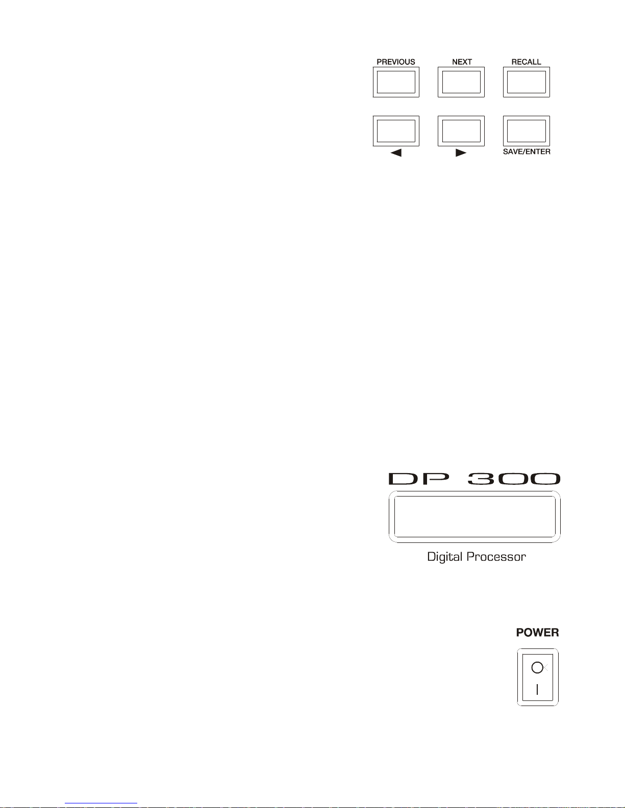
58
Botones PREVIOUS y NEXT
Estos botones permiten que el usuario pueda cambiar
de una pantalla a otra a partir de la selección realizada dentro
del menú mediante la pulsación del encoder. Si estamos, por
ejemplo, dentro de la pantalla SETUP, la pulsación de los
botones PREVIOUS y NEXT permitirá pasar de un parámetro
ajustable a otro dentro del menú SETUP.
Botones ? y ?
Se utilizan para realizar los ajustes dentro de la pantalla seleccionada mediante los botones
PREVIOUS y NEXT. Si son parámetros numéricos, se incrementará o decrecerá el valor y si son
caracteres nos permitirá acceder a una lista de opciones diferentes. Realiza la misma función que la
rotación del encoder.
Botón SAVE/ENTER
Este botón se utiliza para guardar nuevos programas en la memoria de la unidad. Se utiliza
además como función de ENTER para confirmar ciertas operaciones.
Botón RECALL
Este botón se utiliza para cargar programas ya realizados y que están almacenados en la
memoria del DP300. Si el aparato es nuevo, no dispone de ningún programa almacenado. Para cargar
un programa almacenado en la unidad, deberemos pulsar la tecla RECALL y seleccionar el programa
que se desea cargar mediante las teclas PREVIOUS y NEXT. Una vez seleccionado, pulsar de nuevo la
tecla RECALL.
Display LCD
El display LCD está retro-iluminado en azul y dispone de
dos líneas de 16 caracteres cada una de ellas.
Se puede dividir en cuatro zonas informativas diferentes:
1. La parte superior izquierda que muestra información de las
entradas (IN) o salida (OUT) sobre la que estamos
actuando.
2. La parte inferior izquierda que muestra el parámetro
actualmente seleccionado dentro de la entrada o salida sobre la que actuamos.
3. La parte inferior derecha muestra el valor asociado al parámetro seleccionado.
4. La parte superior derecha muestra información relativa al estado actual del DP300. Cuando se
ha realizado alguna modificación en el programa actual se muestra un asterisco.
Interruptor de ON-OFF
Sirve para poner en servicio y apagar la unidad. Asegurarse de que la instalación
eléctrica esté correctamente realizada antes de proceder a la conexión del sistema.
Page 59
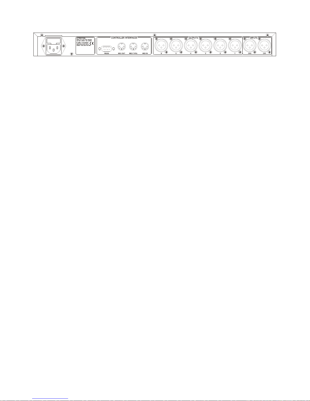
59
5. PANEL POSTERIOR
El panel posterior dispone de las conexiones siguientes:
Base de red
El DP300 dispone, para su alimentación, de una base de red IEC de 3 contactos. Al disponer de
fuente de alimentación conmutada, los márgenes de tensión de funcionamiento van de 90V a 264V AC,
a una frecuencia entre 47 a 63Hz. Antes de arrancar la unidad, deberemos asegurarnos que el DP300
esté correctamente conectado a tierra y en una instalación que cumpla con las normas locales.
Conector RS-232
Dispone de un conector D-SUB 9 para la conexión serie RS-232. Esta conexión se utiliza para
conectar el DP300 con el ordenador PC y realizar así la comunicación entre el DP300 y el software
remoto de control de parámetros del procesador.
Conectores MIDI
Dispone de tres conectores DIN de 5 contactos para las conexiones MIDI. Dispone de un
conector MIDI IN, uno MIDI THRU y otro MIDI OUT.
Conectores de Entrada (CH1 y CH2) y Salida (OUTPUT1-6)
El DP300 dispone de dos entradas (CH1 y CH2) mediante bases XLR hembra de 3 contactos.
Estas bases están configuradas con el pin 1 a masa, el pin 2 a señal + (positivo) y el pin 3 a
señal - (negativo). La salida de señal del DP300 se realiza a través de seis salidas (OUTPUT1-6)
mediante conectores XLR macho de 3 contactos. Como en las entradas, las bases están configuradas
con el pin 1 a masa, el pin 2 a señal + (positivo) y el pin 3 a señal - (negativo).
Page 60
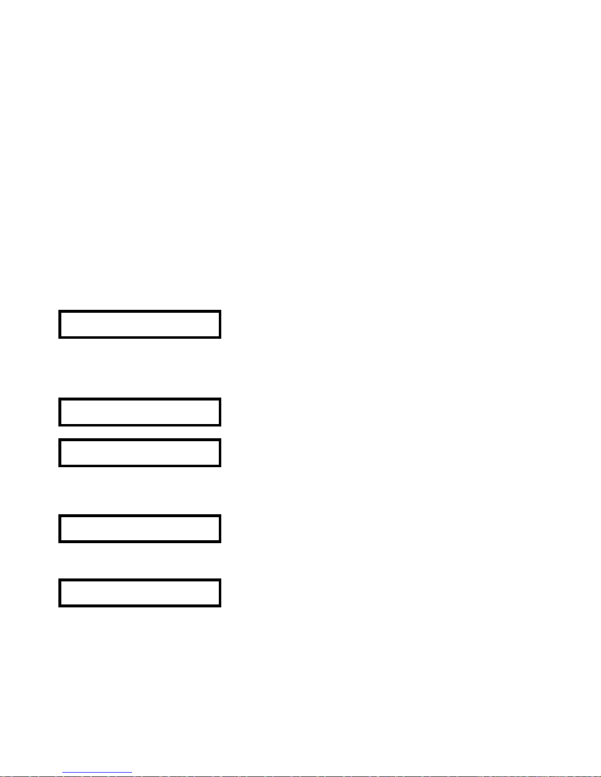
60
6. MODO CONFIGURACIÓN (SETUP)
Una vez conectado deberemos proceder a configurar el aparato para elegir el modo de funcionamiento.
Partiendo de la pantalla de inicio y pulsando la tecla PREVIOUS, accederemos a las pantallas del menú
SETUP que nos permitirán configurar la unidad.
Los parámetros que podremos ajustar desde el menú SETUP serán los siguientes:
1. Modo de funcionamiento, Mono, 2x3 vías y 3x2 vías (LCR 2 way). Stereo Link.
2. Modo de funcionamiento de los filtros (Xover mode).
3. Ajuste de las unidades de retardo (Delay).
4. Ajuste del contraste de la pantalla.
5. Bloqueos de seguridad (Lock).
6. Funcionamiento MIDI.
7. Borrado de programas "Delete Program".
1. Modo de funcionamiento Mono, 2x3 vías y 3x2 vías (LCR 2 way). Stereo Link
El modo LCR (Left, Center, Right) 2 vías, significa que además de las dos vías izquierda y derecha
existe una tercera vía auxiliar a la que denominamos “central”.
Partiendo de la pantalla de inicio, pulsaremos la tecla PREVIOUS y aparecerá la pantalla siguiente:
SETUP
CONFIG MONO
Si giramos el ENCODER hacia la derecha o pulsamos de la tecla ? irán apareciendo de forma
sucesiva las pantallas que nos permitirán cambiar la configuración de MONO a 2 o 3 VÍAS. De origen,
el aparato se suministra en modo MONO.
Change to 3 way?
Enter to confirm
o
Change to 2 way?
Enter to confirm
Pulsaremos la tecla ENTER para confirmar la selección.
Si seleccionamos 2 way (2 VÍAS) aparecerá la siguiente pantalla.
SETUP
CONFIG LCR 2 way
Si seleccionamos 3 way (3 VÍAS) aparecerá la siguiente pantalla.
SETUP
CONFIG 2ch 3 way
Page 61
61
Al seleccionar el modo 2 vías o 3 vías, aparecerá automáticamente una nueva pantalla.
SETUP
Stereo Link ON
o
SETUP
Stereo Link OFF
La pantalla de Enlace Estéreo (Stereo Link) permite realizar la unión estéreo de varios parámetros de
Entrada y Salida, y funciona unida a los ajustes de SETUP (Configuración). Al modificar un parámetro
de uno de los canales enlazados se modificará automáticamente el mismo parámetro de la "pareja".
En modo 2x3 vías, se emparejan de la siguiente forma:
OUT 1 con OUT 2
OUT 3 con OUT 4
OUT 5 con OUT 6
En modo 3x2 vías (LCR 2 Way), se emparejan de la siguiente forma:
OUT 1 con OUT 2
OUT 4 con OUT 6
OUT 3
OUT 5
Funciones STEP y OFFSET
Para definir los parámetros de enlace estéreo, deberemos elegir entre el modo STEP y el modo
OFFSET.
§ El modo STEP permite realizar conexiones tales como tipo de filtro, pendiente del filtro pasa altos,
polaridad de salida, etc. Si se trabaja en modo STEP y se modifica un parámetro en uno de los
canales enlazados, automáticamente se modificará el mismo parámetro del otro, tomando el mismo
valor.
§ En modo OFFSET no dispone de ningún tipo de selección, sólo tiene una serie de valores
numéricos como frecuencia, ganancia o retardo. Al enlazar los canales, se podrá compensar estos
parámetros entre ellos. La siguiente tabla nos informa del tipo de enlaces entre parámetros.
Page 62
62
PARÁMETRO TIPO DE ENLACE 2X3 VÍAS 3X2 VÍAS (LCR 2WAY)
"Delay" de entrada Offset A(CH1)-B(CH2) A(CH1)-B(CH2)
Tipo de EQ de entrada Step A(CH1)-B(CH2) A(CH1)-B(CH2)
Frec. de la EQ de entrada Offset A(CH1)-B(CH2) A(CH1)-B(CH2)
Gan. (+/-) EQ de entrada Offset A(CH1)-B(CH2) A(CH1)-B(CH2)
Nombre de la salida Offset 1-2, 3-4, 5-6 1-3, 4-6
Fuente de la salida Offset A(1,3y5) y B(2,4y6) A(1y4)/B(2y6)/A+B(3y5)
Ganancia de salida Offset 1-2, 3-4, 5-6 1-3, 4-6
Limitador de salida Offset 1-2, 3-4, 5-6 1-3, 4-6
"Delay" de salida Offset 1-3, 3-5, 2-4, 4-6 1-4, 2-5, 3-6
Enlace "delay" de salida Offset 1-3, 3-5, 2-4, 4-6 1-4, 2-5, 3-6
Polaridad de salida Step 1-2, 3-4, 5-6 1-3, 4-6
Curva de graves de salida Step 1-2, 3-4, 5-6 1-3, 4-6
Frec. de graves de salida Offset 1-2, 3-4, 5-6 1-3, 4-6
Curva de agudos de salida Step 1-2, 3-4, 5-6 1-3, 4-6
Frec. de agudos de salida Offset 1-2, 3-4, 5-6 1-3, 4-6
Tipo de EQ de salida Step 1-2, 3-4, 5-6 1-3, 4-6
Frec. de EQ de salida Offset 1-2, 3-4, 5-6 1-3, 4-6
Gan. (+/-) de EQ de salida Offset 1-2, 3-4, 5-6 1-3, 4-6
Ancho de EQ salida Offset 1-2, 3-4, 5-6 1-3, 4-6
Modo MONO
En modo MONO, la configuración de la unidad queda de la siguiente manera:
− Todas las salidas (1-6), quedan conectadas a la entrada CH1 (A).
− Las frecuencias de corte se ajustan a la banda de audio. Funcionamiento toda banda (full
range).
− El enlace por defecto del Delay es apagado (Off).
− No se pueden realizar enlaces estéreo (Stereo Link).
− Los nombres de cada una de las salidas irán de "Band 1" a "Band 6" para las salidas "OUT 1" a
la "OUT 6" respectivamente.
Page 63
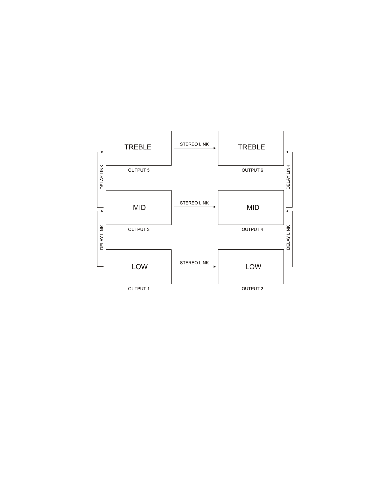
63
Modo 2 x 3 Vías (2 Channel 3 Way)
En modo 2 Canales 3 Vías, la configuración de la unidad queda de la siguiente manera:
− Las salidas 1, 3 y 5, quedan conectadas a la entrada CH1(A).
− Las salidas 2, 4 y 6, quedan conectadas a la entrada CH2(B).
− El enlace por defecto del Delay es apagado (Off).
− Se activará (On) el enlace estéreo (Stereo Link).
− Los nombres asignados a cada una de las salidas serán:
OUT 1 y OUT 2 - Low (graves)
OUT 3 y OUT 4 - Mid (medios)
OUT 5 y OUT6 - High (agudos)
Modo 3 x 2 Vías (LCR 2 Way)
En modo LCR (Left, Center, Right) y 2 Vías, la configuración de la unidad queda de la siguiente
manera:
− Las salidas 1 y 4, quedan conectadas a la entrada CH1(A).
− Las salidas 3 y 6, quedan conectadas a la entrada CH2(B).
− Las salidas 2 y 5 quedan conectadas a la entrada SUM CH1(A)+CH2(B).
− El enlace por defecto del Delay es apagado (Off).
− Se activará (On) el enlace estéreo (Stereo Link).
− Los nombres asignados a cada una de las salidas serán:
OUT 1 & 3 - Low (graves)
OUT 2 - C Low (graves central)
OUT 4 & 6 - High (agudos)
OUT 5 - C High (agudos central)
Page 64
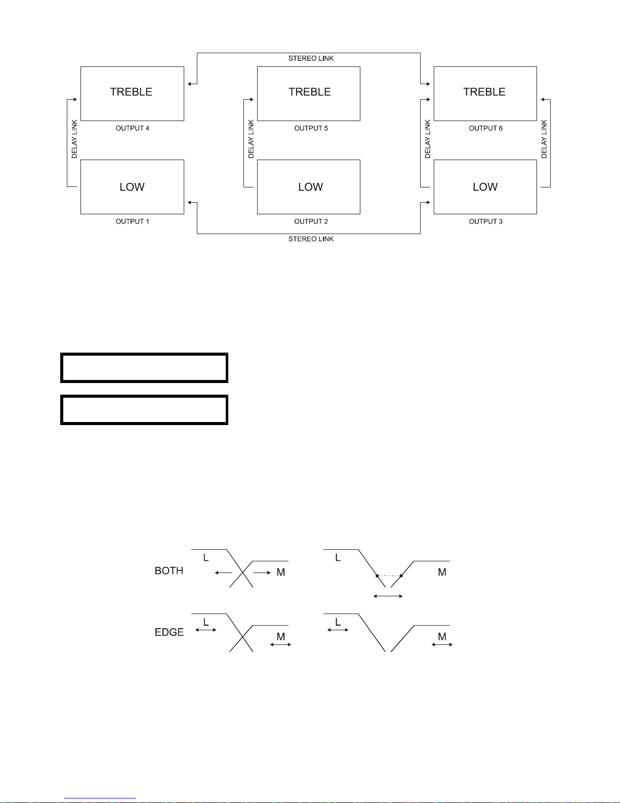
64
Una vez elegido el modo funcionamiento, podremos configurar todos los parámetros que nos permitirán
trabajar con el aparato de la manera que más nos convenga.
2. Modo de funcionamiento de los filtros (Xover mode)
Esta pantalla nos permitirá configurar el modo en que actuaremos sobre los filtros en cada una de las
entradas o las salidas. Disponemos de dos opciones de configuración, BOTH y EDGE.
SETUP
Xover Mode Both
o
SETUP
Xover Mode Edge
En modo BOTH al modificar la frecuencia de corte superior, por ejemplo un canal de graves, esta
modificación de la frecuencia arrastrará la frecuencia de corte inferior del filtro de medios adyacente,
modificándola. No es necesario que se mantenga siempre la misma relación entre ambas frecuencias,
pudiéndose ajustar un "offset" entre ellas. En modo BOTH cuando cambiamos, por ejemplo, la
pendiente superior del filtro de un canal de salida ajustada como LO (graves), también modificaremos la
pendiente inferior del filtro del canal adyacente ajustado como MID (medios).
En modo EDGE, podremos ajustar de forma separada todas las frecuencias de corte de los filtros, sin
que la variación de una de ellas, modifique la adyacente.
Page 65
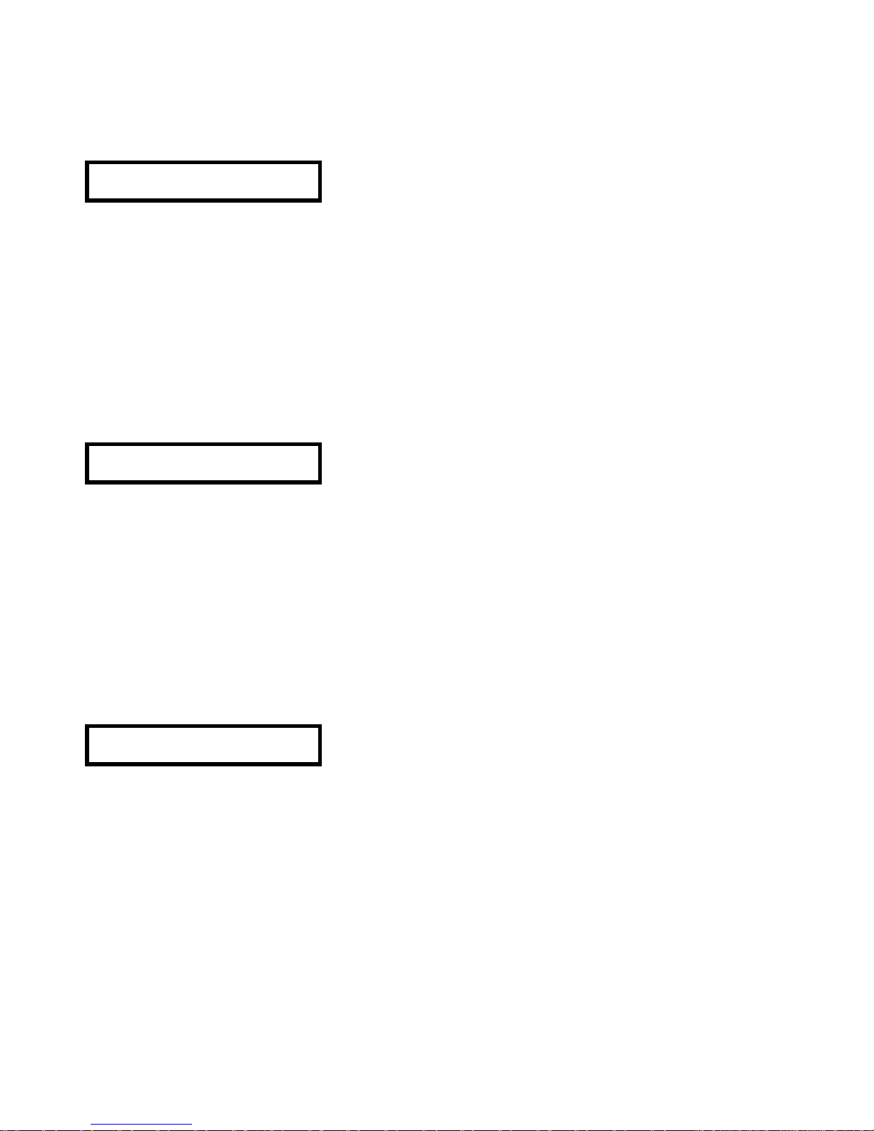
65
3. Ajuste de las unidades de retardo (Delay)
Esta pantalla nos permitirá elegir las unidades con las que trabajará el parámetro de Delay
dependiendo del tipo de aplicación. Podremos ajustar el valor de retardo de 0 a 635ms en pasos de
21µs.
SETUP
Delay Units ms
Podremos elegir entre:
- Milisegundos (ms)
- Metros (m)
- Pies (ft)
- Frames por segundo (24, 25 ó 30)
Para cambiar entre una unidad y otra deberemos utilizar la rueda del encoder o las teclas ? y ?.
4. Ajuste del contraste de la pantalla
Esta pantalla nos permitirá ajustar el contraste del visor LCD.
SETUP
Contrast /
Realizar el ajuste deseado mediante la rueda del encoder o las teclas ? y ?.
5. Bloqueos de seguridad (Lock)
El DP300 dispone de tres niveles de bloqueo de seguridad diseñados para proteger el sistema y los
programas o parámetros ajustados en la unidad contra utilizaciones erróneas o no deseadas. Se trata
de "Lock Out", "Owner Lock" y "OEM Lock".
-Lock Out
Esta es la primera pantalla de bloqueo que encontraremos. Este nivel de bloqueo es el más básico de
los tres.
SETUP
Lock Out Off
Puede estar a "Off" (desactivado) o a "On" (activado). Si está a "On", afecta los parámetros y funciones
siguientes:
-No se podrá ajustar ningún parámetro (excepto Lock Out y contraste del Display)
-Los pulsadores de "Mute" están inactivos.
-No se pueden guardar o cargar programas.
Para desbloquear de nuevo la unidad, bastará acceder a la pantalla de Lock Out y ajustar el parámetro
de bloqueo a "Off".
Page 66
66
-OEM Lock
¡Atención!: Guardar la contraseña en lugar seguro. No hay forma de desbloquear la unidad sin
esta contraseña.
El bloqueo "OEM" permitirá bloquear todos o alguno de los parámetros editados en un programa. Los
bloqueos quedarán almacenados en el propio programa.
Aparecerá la siguiente pantalla:
SETUP
OEM Lock Off
Si pulsamos la tecla ?o giramos el encoder hacia la derecha aparecerá una pantalla donde se nos
preguntará por el "PASSWORD" (contraseña).
OEM PASSWORD
-
Deberemos introducir la contraseña utilizando las teclas PREVIOUS y NEXT o la rueda del encoder
para seleccionar la letra y las teclas ? y ? para cambiar de un dígito a otro. La contraseña por defecto
en el DP300 es ECLER. Si se introduce una contraseña equivocada aparecerá un mensaje de error,
WARNING!
Password wrong
y regresará a la pantalla inicial de OEM Lock.
Una vez introducida la contraseña, pulsaremos la tecla ENTER para confirmarla.
Aparecerá brevemente el mensaje siguiente,
Lock Setup OEM
Enter when done
entrando después automáticamente en el modo "Lock All".
Lock Setup OEM
Lock all? No
Una vez en el modo "Lock All" (Bloquear Todo), podremos bloquear todos los parámetros, pudiéndolos
desbloquear posteriormente de forma selectiva. Para bloquear todos los parámetros giraremos la rueda
del encoder o las teclas ? y ?hasta que aparezca palabra "Yes" (Sí). En este momento, el sistema nos
pedirá la introducción de la nueva contraseña. Podemos introducir la misma o una nueva.
En caso de querer desbloquear algún bloqueo previo, seleccionaremos "Yes" primero y "No" después.
Para no ejecutar esta opción, pulsaremos la tecla SAVE/ENTER.
Una vez bloqueado el programa nos lo indicará con un rombo en la parte inferior derecha del display.
Page 67
67
Modo "Lock Setup" (Ajuste del Bloqueo)
Una vez en este punto si se pulsa alguna de las teclas PREVIOUS o NEXT, entraremos en el modo de
"Lock Setup" (Ajuste del Bloqueo). Este modo nos permitirá acceder a todas las pantallas de las
Entradas y las Salidas pero con restricciones:
− No se pueden variar los valores de los parámetros.
− No se puede acceder a los menús de SAVE y de RECALL.
− Sólo se podrán bloquear los parámetros de SETUP y Stereo Link.
− Se deberán bloquear o desbloquear los parámetros de forma individual, independientemente
que el enlace estéreo (stereo link) esté activado o no.
Si un parámetro está desbloqueado, se mostrará una pantalla con su nombre, su valor y a qué entrada
o salida pertenece. Si pulsamos la tecla ? o giramos el encoder en sentido horario, modificaremos el
valor de bloqueo, y aparecerá una marca para indicar que se ha modificado este valor. Se deberán
seleccionar aquellos parámetros que se deseen bloquear, apareciendo en todos ellos la marca de
modificación.
En caso de estar todos los parámetros bloqueados (Block All), desbloquearemos aquellos que
deseemos de la misma forma.
Por ejemplo aparecerá la pantalla.
IN A OEM
Delay v
Las ecualizaciones que no estén asignadas, no se mostrarán en pantalla en el modo "Lock Setup"
(Ajuste de Bloqueo). Esto evitará que el usuario asigne ecualizaciones adicionales. Si tratamos de
realizar una nueva ecualización, aparecerá la pantalla siguiente,
No more Eqs own
Lock unused? v
pudiéndose dejar activada la posibilidad de añadir nuevas ecualizaciones.
Confirmación de la selección de bloqueo
Una vez seleccionados todos los parámetros que se deseen bloquear, deberemos confirmar la
selección pulsando la tecla SAVE/ENTER. Se mostrará de nuevo la pantalla donde se pide la
introducción de la contraseña. Se deberá introducir la contraseña del modo especificado anteriormente.
Una vez introducida la contraseña deberemos pulsar de nuevo ENTER a fin de confirmarla. Una vez
confirmada, el DP300 regresará al menú SETUP.
El DP300 estará ahora bloqueado, aunque no mostrará ningún símbolo que así lo indique. Sólo serán
accesibles aquellos parámetros no bloqueados mientras que aquellos que sí lo estén, ni siquiera
aparecerán en pantalla para su reajuste. Si se modifica algún parámetro no bloqueado de un programa
que sí lo esté, deberemos guardar los ajustes en un nuevo programa. Si se desea reocupar la misma
posición de programa, se deberá borrar primero el programa que ocupe esa posición mediante la
función "Delete Prog" del menú SETUP.
Page 68
68
Owner Lock
¡Atención!: Guardar la contraseña en lugar seguro. No hay forma de desbloquear la unidad sin
esta contraseña.
El modo de bloqueo "Owner Lock" es el segundo nivel de seguridad del DP300 y funciona de la misma
manera que el modo OEM, con el cambio del término "OEM" por el de "Own", y con el cambio de
símbolo de bloqueo. Podemos utilizar ambos niveles de bloqueo a la vez para bloquear los parámetros
que deseemos. La contraseña por defecto de "Owner Lock" en el DP300 es USER.
6. Funcionamiento MIDI
El DP300 de ECLER está preparado para utilizar comandos MIDI. Disponemos de varias pantallas que
nos permitirán ajustar los parámetros de MIDI para que funcionen tal y como sea necesario para
nuestro sistema.
Aparte de la comunicación MIDI, el DP300 dispone de una conexión RS232 para establecer una
comunicación serie con un ordenador que disponga del programa de edición y control dp:lab
(suministrado con la unidad). Este programa permitirá realizar ajustes y programaciones del DP300 de
forma remota desde el ordenador.
Ajuste de canal de MIDI (1-16)
Esta pantalla permitirá ajustar el canal utilizado para transmitir y recibir comandos MIDI entre el DP300
y el sistema MIDI remoto. Podremos elegir canales entre el 1 y el 16. Realizar el ajuste deseado
mediante la rueda del encoder o las teclas ? y ?.
Tener en cuenta que, para que exista la comunicación, tanto el DP300 como el sistema MIDI remoto
deberán estar configurados en el mismo canal.
SETUP
Midi channel 1
Ajuste del modo MIDI
Esta pantalla permite ajustar el tipo de información que el DP300 podrá transmitir a través de la base
posterior MIDI OUT y dependerá de la utilización del DP300 dentro del sistema. Podremos elegir entre
los modos siguientes:
-Off (apagado)
-Program (Prog)
-Thru
-Master
-PCPort
Off
No se podrá transmitir ningún tipo de mensaje MIDI a excepción de comunicaciones "MIDI Sysex"
(systems exclusive) exclusivamente del sistema.
SETUP
Midi Mode Off
Page 69
69
Program (Prog)
Permite que la unidad pueda transmitir o recibir cambios de programación MIDI.
SETUP
Midi Mode Prog
Thru
Permite que la señal MIDI recibida por la entrada MIDI In, esté presente al mismo tiempo en la salida
MIDI Out.
SETUP
Midi Mode Thru
Master
Permite la transmisión de todas las órdenes de control de cambios con otros aparatos con el mismo
canal MIDI. Esta opción es útil, por ejemplo, para que dos unidades DP300 funcionen en paralelo para
aplicaciones estéreo.
SETUP
Midi Mode Master
PCPort
Permite la utilización del puerto RS-232 del DP300 para establecer comunicación con el ordenador que
disponga del programa dp:lab (suministrado con el DP300). Además permite al DP300 formar parte de
sistemas MIDI, realizar descargas exclusivas del sistema y controlar otras unidades DP300.
SETUP
Midi Mode PCPort
Transmisión de información "MIDI Systems Exclusive Dump"
Esta pantalla se utiliza para transferir informaciones exclusivamente del sistema MIDI Sysex entre
aparatos DP300 o entre unidades DP300 y secuenciadores u ordenadores capaces de soportar este
tipo de comunicaciones de sistema MIDI. Para realizar la comunicación deberemos conectar un cable
MIDI entre la salida MIDI Out de la unidad emisora y la entrada MIDI In de la receptora.
La primera pantalla que aparecerá será la siguiente:
SETUP
Midi Dump No
Si pulsamos la tecla ? o giramos la rueda del encoder hacia la derecha, aparecerá la pantalla
siguiente:
Midi Dump?
Enter to confirm
Page 70
70
En este momento, se enviará un mensaje MIDI Sysex que el aparato receptor interpretará como una
entrada de información MIDI de sistema. El receptor mostrará un mensaje que informará de esta
situación.
Si no queremos que en la unidad receptora se sobrescriban todas las memorias deberemos pulsar la
tecla ? del aparato receptor para modificar la pantalla de "Allow Dump" a "No". El aparato receptor
volverá a su funcionamiento normal e ignorará la información entrante.
Si en cualquier momento queremos abandonar el modo MIDI Dump, deberemos pulsar alguna de las
dos teclas PREVIOUS o NEXT.
Una vez pulsemos la tecla "SAVE/ENTER", la unidad empezará a ejecutar el procedimiento de
transmisión MIDI Dump y aparecerá la pantalla siguiente,
Midi Dump?
Preparing…
e inmediatamente después aparecerá la misma pantalla con una cuenta ascendente de 0% a 100%. Al
llegar al 100% significará que se ha transmitido toda la información.
Midi Dump?
XX%
Tener en cuenta que si se transmite una información MIDI Sysex a una unidad diferente o no
compatible se pueden dañar las memorias de la unidad receptora. Al realizar la transmisión, deberemos
tener las unidades diferentes o no compatibles apagadas o en un canal MIDI diferente con el fin de
evitar daños en la información almacenada.
7. Borrado de programas "Delete Program"
Mediante esta pantalla, podremos borrar alguno de los programas guardados en la unidad. La primera
pantalla en aparecer será:
SETUP
Delete Prog No
Si pulsamos la tecla ? o giramos la rueda del encoder hacia la derecha, entraremos en modo Borrado
de Programa (Delete Program) y aparecerá la pantalla siguiente,
Enter to Delete
6DIGITAL6
donde podremos seleccionar el programa a borrar mediante la rueda del encoder o las teclas ? y ?.
Una vez seleccionado el programa a borrar, pulsaremos la tecla SAVE/ENTER para borrar el programa.
Tener en cuenta que los programas que estén bloqueados deberán ser desbloqueados antes de
realizar el borrado.
Page 71
71
7. ENTRADAS
El DP300 dispone de las entradas A (CH1), B (CH2) y la suma de ambas, SUM A+B.
Dependiendo del modo de funcionamiento, las entradas estarán agrupadas de diferente manera.
En modo Mono, funcionarán de forma independiente,
IN A(CH1)
IN B(CH2)
IN A + IN B
y tanto en modo 2 x 3 way (2 canales y 3 vías) como LCR 2 way (3 x 2 vías), la agrupación será la
siguiente:
INA & INB
IN SUM A+B
Si no deseamos disponer del enlace estéreo, (Stereo Link = Off), las entradas se podrán ajustar de
forma independiente, sin estar agrupadas.
Tanto en la entrada A(CH1) como en la B(CH2) se pueden modificar los parámetros de ecualización
(Eq) y de Delay (retardo), mientras que en la entrada SUM A+B sólo se pueden modificar los
parámetros de Delay.
Se podrá acceder y cambiar de una pantalla a otra pulsando el encoder.
En cualquiera de las pantallas de las entradas, podremos modificar el valor de los parámetros mediante
las teclas ? y ? o la rotación del encoder. Para cambiar de un parámetro a otro dentro de la entrada
seleccionada deberemos pulsar las teclas PREVIOUS o NEXT.
Delay (retardo)
En las entradas A (CH1) y B (CH2) la primera pantalla visualizada será la de "Delay" (retardo), donde
podremos ajustar su valor hasta un máximo de 635ms.
IN A
Delay 0.000ms
Ecualización (Eq)
Se puede asignar una o varias ecualizaciones a cada una de las entradas A (CH1) y B (CH2) ya sea
tipo Shelving de graves o agudos con pendientes de 12dB/octava o 6dB/octava o tipo campana (bell)
totalmente paramétrico. Para asignar estas ecualizaciones, deberemos ajustar una serie de parámetros
que determinarán el tipo de ecualización o ecualizaciones de este canal.
Los parámetros que aparecerán cada vez que pulsemos la tecla PREVIOUS serán:
1. Tipo de ecualización.
2. Frecuencia de ecualización.
3. Ganancia de la ecualización.
4. Ancho de la ecualización Wd (Width).
1. Tipo de ecualización
Si pulsamos la tecla PREVIOUS aparecerá la primera pantalla para realizar el ajuste de los parámetros
del ecualizador. En esta pantalla podremos elegir el tipo de filtro.
IN A & IN B
Eq1S Bel Sp8
Page 72
72
En el caso de esta pantalla, la "S" del texto Eq1S indica que se trata de un canal con enlace estéreo, lo
que significa que los parámetros que modifiquemos en una entrada se modificarán también en la otra.
En el caso de que se trate de una entrada Mono, sin enlace estéreo, aparecerá una pantalla como la
siguiente,
IN A
Eq1 Bel Sp8
donde podemos ver que el texto se convierte en "Eq1", y desaparece la "S".
Podremos elegir entre los tipos de filtro siguientes:
Bell (campana)
Lo12- Graves 12dB/octava
Lo6- Graves 6dB/octava
Hi12-Agudos 12dB/octava
Hi6-Agudos 6dB/octava
La parte superior izquierda muestra a qué entrada se aplicará la ecualización. En este caso se trata de
la entrada IN A (CH1).
El parámetro Sp indica el número de filtros DSP que quedan todavía disponibles. En caso que aparezca
Sp0 significa que ya no quedan filtros disponibles en el DSP.
2. Frecuencia de ecualización
La frecuencia de ecualización es aquella que está situada en el centro de la curva del filtro. Es la
llamada “frecuencia de resonancia”. Podremos ajustar la frecuencia desde 15Hz hasta 16kHz en saltos
de aproximadamente 1/6 de octava.
IN A
Eq1 Fq 1.00kHz
Podremos modificar el valor de la frecuencia mediante la rueda del encoder o las teclas ? y ?.
3. Ganancia de la ecualización
A cualquiera de las ecualizaciones (Eq) que se asignen a una entrada se le deberá dar un valor de
ganancia positiva o negativa.
IN A
Eq 1 + - +15.0dB
Esta ganancia es ajustable entre –15dB y +15dB mediante la rotación del encoder o las teclas ? y ?.
Si no se asigna ganancia la ecualización no estará operativa. En el momento que se asigne una
ganancia a una ecualización, por ejemplo la Eq1, quedará operativa y podremos pasar
automáticamente a ajustar los parámetros de la siguiente ecualización de esta entrada, que en este
caso será Eq2.
A medida que realicemos diferentes ecualizaciones se irá reduciendo el número de recursos del DSP y
disminuyendo el valor de Sp, que nos indica la cantidad de filtros disponibles. La cantidad de filtros
disponibles puede variar, ya que existen ciertas restricciones dependiendo del uso y las asignaciones
utilizadas.
Para conocer las restricciones, consultar el punto “Recursos del DSP” en éste manual.
Page 73

73
4. Ancho de la ecualización Wd (Width)
El parámetro Wd indica la anchura del filtro en ecualizaciones tipo “Bell” (campana). Está disponible
sólo para este tipo de ecualizaciones.
IN A
Eq1 Wd 0.300ct
Se pueden seleccionar valores entre 0,05 octavas y 3 octavas en saltos de 0,05 octavas.
El valor del parámetro "Wd" indica la cantidad de octava que ocupará el filtro a partir de la frecuencia de
resonancia de la ecualización. Cuanto menor sea el valor de Wd, más estrecha será la “campana” de la
ecualización, efectuando una ecualización más selectiva sobre la frecuencia especificada. A medida
que aumentamos el valor de Wd el filtro se vuelve más ancho, la curva se suaviza y la ecualización no
afecta tan selectivamente a una frecuencia determinada sino que afecta también a las frecuencias
adyacentes a la central.
Es habitual trabajar con valores de Wd=0,3 (1/3 de octava).
En este momento ya tendremos creada una primera ecualización para esta entrada.
Si el canal tiene programadas varias ecualizaciones diferentes, al pulsar de nuevo la tecla PREVIOUS,
entraremos en la pantalla inicial (tipo de filtro) de la segunda ecualización, y así sucesivamente hasta
que terminemos con todas las ecualizaciones de la entrada.
Page 74
74
8. SALIDAS
El DP300 dispone de seis salidas (OUTPUT 1-6) agrupadas de forma diferente dependiendo de la
configuración de funcionamiento.
En modo Mono, el DP300 dispone de seis salidas que funcionan de forma independiente.
Por defecto, y debido a que en modo 2 x 3 way (2 canales y 3 vías) las salidas disponen de un "enlace
estéreo" (Stereo link = on") están agrupadas de la forma siguiente:
Salida 1 y 2 (OUT1 & OUT2)
Salida 3 y 4 (OUT3 & OUT4)
Salida 5 y 6 (OUT5 & OUT6)
En modo 3 x 2 way (Left Center Right 2 vías), están agrupadas de la forma siguiente:
Salida 1 y 3 (OUT1 & OUT3)
Salida 2 (OUT 2)
Salida 4 y 6 (OUT4 & OUT6)
Salida 5 (OUT 5)
Si no deseamos disponer del enlace estéreo, ajustaremos el valor de "Stereo Link" a Off de manera que
podremos modificar los parámetros de cada una de las salidas de forma independiente.
Cuando las salidas están enlazadas, al modificar un parámetro de una de ellas, el parámetro de la
salida asociada variará exactamente de la misma manera.
Para acceder a cada una de las salidas, se deberá realizar una pulsación en el encoder. Una vez dentro
de la pantalla de la salida que se desee ajustar se deberá pulsar la tecla PREVIOUS o NEXT para
acceder a las diferentes pantallas de ajuste de parámetros de esta salida.
Una vez en la pantalla de ajuste deseada, podremos modificar el parámetro mediante la rotación del
encoder o la pulsación de las teclas ? y ?.
En cada una de las salidas, nos encontraremos con las pantallas siguientes:
1. Nombre de la salida.
2. Fuente de la señal (Source).
3. Ganancia (Gain).
4. Limitador (Limit).
5. Retardo (Delay).
6. Enlace de retardos (Delay Link).
7. Polaridad (Polarity).
8. Tipo de pendiente inferior del filtro (Lo Shape).
9. Frecuencia inferior del filtro (Hi pass).
10. Tipo de pendiente superior del filtro (Hi Shape).
11. Frecuencia superior del filtro (Lo pass).
12. Ecualización (Eq).
1. Nombre de la salida
A cada una de las salidas y, dependiendo del modo de funcionamiento, se le asigna un nombre por
defecto. Normalmente, este nombre por defecto irá de Band 1 a Band 6 para cada una de las salidas
1 a 6.
OUT 1&3 Band 1
Name Band 1
Page 75
75
Si queremos modificar este nombre, el DP300 dispone de una serie de nombres pre-programados para
que los podamos asignar a cada salida dependiendo de la función que cumpla dentro del sistema de
sonido. Son los siguientes:
Band 1-6
L Low, L Mid, L High
R Low, R Mid, R High
C Low, C Mid, C High
Subs, Low, Lo Mid, Mid, Hi Mid, High
Mid+High
2"Horn, 1"Horn
Bullet
Flat
Unused
Bar, BStage
Delay
Centre
Mono
Aux
10", 12", 15", 18", 21", 24"
1.5"Hn
Delay1, Delay2, Delay3, Delay4, Delay5, Delay6
L Subs, C Subs, R Subs
Para seleccionar el nombre que queramos asignar, se deberá utilizar la rotación del encoder o las
teclas ? y ?.
2. Fuente de la señal (Srce)
Cada salida deberá estar asignada a una de las entradas, que es de donde va a tomar la señal a la que
afectarán todos los parámetros que se le apliquen.
A cada salida se le pueden asignar las entradas siguientes:
Entrada INA (CH1)
Entrada INB (CH2)
Entrada IN SUM A+B
OUT 1 Band 1
Srce IN A
En este caso, estamos en modo Mono con la Salida 1 (OUT1) asignada a la entrada INA (CH1).
Normalmente en los modos que dispongan de enlace estéreo, la selección normalmente utilizada es la
de Inputs A&B. En el modo Mono o los modos estéreo sin enlace estéreo, podremos asignar la entrada
que deseemos a cada una de las salidas.
Page 76
76
3. Ganancia
La ganancia (gain) de cada una de las salidas se podrá ajustar de -15dB a +15dB en pasos de 0,2dB.
El ajuste por defecto de cada una de las salidas es de 0dB.
OUT 1 Band 1
Gain 0.0dB
Atención: Se deberá tener en cuenta que el nivel de ganancia, sumado a otros parámetros que
incrementen el nivel de la señal (p. ej. ecualizaciones de entrada o salida con ganancia positiva)
no provoquen un nivel de salida que sature la entrada del amplificador. Esta situación podría
dañar los altavoces.
Para modificar el nivel de "gain" se deberá utilizar la rotación del encoder o las teclas ? y ?.
4. Limitador (Limit)
Cada una de las salidas dispone de un limitador que se puede ajustar a cualquier nivel entre -10,0dBV y
+20,0dBV, en saltos de 0,2dBV.
OUT 1 Band 1
Limit 0.4dBV
El ajuste correcto del limitador puede llegar a ser muy importante en caso de que se necesite proteger
los altavoces contra la señal recortada o el exceso de potencia.
Cuando un amplificador recibe a la entrada un nivel de señal superior a la nominal del propio
amplificador, se puede producir la saturación de la señal de entrada que puede derivar en una señal
amplificada de salida recortada. Esta señal recortada tiene una componente muy importante de tensión
continua, que puede producir daños a los altavoces con mucha facilidad. Para evitar esto, deberemos
ajustar el limitador de forma que evite la saturación de entrada del amplificador evitando así que se
produzcan daños en los altavoces.
De la misma manera, si disponemos de un amplificador que entrega más potencia de la que soportan
las cajas acústicas o si el sistema deberá funcionar durante mucho tiempo a alto nivel, se deberá
ajustar correctamente el limitador para que la potencia entregada por los amplificadores no pueda
dañar los altavoces.
El nivel del umbral del limitador servirá también como referencia al Vúmetro de salida, de manera que
marcará en función del nivel de umbral ajustado en el limitador. Si el limitador está ajustado, por
ejemplo, a 2,0dBV, el nivel de LIMIT del vúmetro de salida corresponderá a +2dBV, de la forma
siguiente:
VÚMETRO NIVEL DE SALIDA
Limit +2,0dBV
-3dB -1dBV
-6dB -4dBV
-12dB -8dBV
-20dB -18dBV
Para modificar el nivel de "Limit" se deberá utilizar la rotación del encoder o mediante la pulsación de
las teclas ? y ?.
Page 77
77
5. Retardo (Delay)
El retardo de cada una de las salidas se podrá ajustar de 0 a 635ms en pasos de 0,021ms.
OUT 1 Band 1
Delay 0.000ms
Las unidades que aparecerán a la derecha del display (milisegundos en este caso) dependerán del
ajuste realizado en "Ajuste de unidades de retardo (Delay)" del menú SETUP.
Deberemos realizar el ajuste que más se adapte al tipo de funcionamiento deseado.
Para modificar el nivel de "Delay" se deberá utilizar la rotación del encoder o la pulsación de las teclas
? y ?.
6. Enlace de retardos (Delay Link)
El enlace de los retardos se utiliza para mantener el "offset" entre canales que dispongan de retardo.
Por ejemplo, si a un canal que disponga de un enlace estéreo le asignamos un retardo, al canal
enlazado se le asignará automáticamente el mismo valor de retardo.
OUT 1 Band 1
Delay Link Off
Dependiendo del modo de funcionamiento sólo podremos asignar unos enlaces de retardo
predeterminados, tal y como se indica a continuación:
Modo Mono
Salida OUT1 con OUT2
Salida OUT2 con OUT3
Salida OUT3 con OUT4
Salida OUT4 con OUT5
Salida OUT5 con Ninguna (Off)
Modo 2 canales 3 vías
Salida OUT1 con OUT3
Salida OUT2 con OUT4
Salida OUT3 con OUT5
Salida OUT4 con OUT6
Salida OUT5 con Ninguna (Off)
Salida OUT6 con Ninguna (Off)
Modo 3 canales 2 vías (LCR)
Salida OUT1 con OUT4
Salida OUT2 con OUT5
Salida OUT3 con OUT6
Salida OUT4 con Ninguna (Off)
Salida OUT5 con Ninguna (Off)
Salida OUT6 con Ninguna (Off)
Para modificar el ajuste se deberá utilizar la rotación del encoder o la pulsación de las teclas ? y ?.
Page 78
78
7. Polaridad (Polarity)
La polaridad de cada una de las salidas puede estar ajustada en "Normal" o en "Invertida" (Invert).
OUT 1 Band 1
Polarity Normal
Si las salidas disponen de enlace estéreo, la modificación de una de ellas provocará la modificación de
la salida enlazada.
Para modificar el ajuste se deberá utilizar la rotación del encoder o la pulsación de las teclas ? y ?.
8. Tipo de pendiente inferior del filtro (Lo Shape)
El DP300 dispone de la posibilidad de disponer de filtros pasa banda en cada una de las salidas. Cada
filtro dispone de una frecuencia de corte inferior y una superior, con un tipo de pendiente asociada cada
una de ellas, lo cual determinará el tipo de filtro utilizado.
Dependiendo de la aplicación, cada usuario podrá elegir entre varias opciones de tipo de filtro e
inclinación de la pendiente a fin de se ajuste perfectamente a sus necesidades.
En esta pantalla, podremos elegir el tipo de pendiente para la frecuencia inferior del filtro. Podremos
elegir entre las siguientes:
Butterworth 6dB/octava (But 6)
Butterworth 12dB/octava (But 12)
Butterworth 18dB/octava (But 18)
Butterworth 24dB/octava (But 24)
Linkwitz-Riley 12dB/octava (L-R 12)
Linkwitz-Riley 24dB/octava (L-R 24)
Linkwitz-Riley 48dB/octava (L-R 48)
Bessel 12dB/octava (Bes 12)
Bessel 24dB/octava (Bes 24)
OUT 1 Band 1
Lo Shape L-R 24
En este caso, tenemos que la salida OUT1 tiene un filtro con pendiente inferior tipo Linkwitz-Riley de
24dB/octava.
El ajuste del tipo de filtro se deberá realizar mediante la rotación del encoder o la pulsación de las teclas
? y ?.
9. Frecuencia inferior del filtro (Hi pass)
En esta pantalla, podremos ajustar la frecuencia de corte inferior del filtro.
OUT 1 Band 1
Hi pass 15.0Hz
Page 79
79
El margen de ajuste de frecuencia va desde los 15Hz hasta los 16kHz, en pasos de 1/6 de octava. Si
intentamos ajustar un valor superior a los 16kHz, aparecerá un texto de "Off" y si intentamos ajustar
uno inferior a los 15Hz, aparecerá el texto "OUT".
Deberemos tener en cuenta que si aumentamos esta frecuencia más allá de los 16kHz, la salida de
este canal se apagará, ya que desplazaremos la curva inferior del filtro a una frecuencia demasiado
alta.
El ajuste de la frecuencia de filtro se deberá realizar mediante la rotación del encoder o la pulsación de
las teclas ? y ?.
10. Tipo de pendiente superior del filtro (Hi Shape)
En esta pantalla, podremos elegir el tipo de pendiente para la frecuencia de corte superior del filtro.
Podremos elegir entre las siguientes:
Butterworth 6dB/octava (But 6)
Butterworth 12dB/octava (But 12)
Butterworth 18dB/octava (But 18)
Butterworth 24dB/octava (But 24)
Linkwitz-Riley 12dB/octava (L-R 12)
Linkwitz-Riley 24dB/octava (L-R 24)
Linkwitz-Riley 48dB/octava (L-R 48)
Bessel 12dB/octava (Bes 12)
Bessel 24dB/octava (Bes 24)
OUT 1 Band 1
Hi Shape L-R 24
En este caso, tenemos que la salida OUT1 tiene un filtro con pendiente superior tipo Linkwitz-Riley de
24dB/octava.
El ajuste del tipo de filtro se deberá realizar mediante la rotación del encoder o la pulsación de las teclas
? y ?.
11. Frecuencia superior del filtro (Lo pass)
En esta pantalla, podremos ajustar la frecuencia de corte superior del filtro.
OUT 1 Band 1
Hi pass 16.0kHz
El margen de ajuste de frecuencia va desde los 15Hz hasta los 16kHz, en pasos de 1/6 de octava. Si
intentamos ajustar un valor superior a los 16kHz, aparecerá un texto de "OUT".
El ajuste de la frecuencia de filtro se deberá realizar mediante la rotación del encoder o la pulsación de
las teclas ? y ?.
Page 80
80
En todos los ajustes que realicemos en los parámetros de filtros deberemos tener en cuenta el ajuste
realizado en los parámetros de "Modo de funcionamiento de los filtros (Xover Mode)" del menú de
configuración SETUP. Si está en modo BOTH, al variar una frecuencia de corte modificaremos la
adyacente, arrastrándola cuando junto a la que modifiquemos. Si está ajustado en modo EDGE, la
modificación de una frecuencia de corte no afectará a la adyacente.
Si existe un enlace estéreo, la modificación del parámetro de filtro de un canal se producirá también en
el canal enlazado.
12. Ecualización
Para cada una de las salidas se puede asignar una o varias ya sea tipo Shelving de graves o agudos
con pendientes de 12dB/octava o 6dB/octava o tipo campana (bell) totalmente paramétrico. Para
asignar estas ecualizaciones, deberemos ajustar una serie de parámetros que determinarán el tipo de
ecualización o ecualizaciones de este canal.
Los parámetros que aparecerán cada vez que pulsemos la tecla PREVIOUS serán:
1. Tipo de ecualización.
2. Frecuencia de ecualización.
3. Ganancia de la ecualización.
4. Ancho de la ecualización WD (Width).
1. Tipo de ecualización
Si pulsamos la tecla PREVIOUS aparecerá la primera pantalla para realizar el ajuste de los parámetros
del ecualizador. En esta pantalla podremos elegir el tipo de pendiente.
OUT 1&2 Band 1
Eq1S Bell Sp8
En el caso de esta pantalla, la "S" del texto Eq1S indica que se trata de un canal con enlace estéreo, lo
que significa que los parámetros que modifiquemos en una salida se modificarán también en la otra.
En el caso de que se trate de una salida sin enlace estéreo aparecerá una pantalla como la siguiente,
OUT 1 Band 1
Eq1 Bell Sp8
Podremos elegir entre los tipos de pendiente siguientes:
Bell (campana)
Lo12- Graves 12dB/octava
Lo6- Graves 6dB/octava
Hi12-Agudos 12dB/octava
Hi6-Agudos 6dB/octava
La parte superior izquierda muestra a qué salida se aplicará la ecualización. En este caso se trata de la
salida OUT1.
El parámetro Sp indica el número de filtros DSP que quedan todavía disponibles. En caso que aparezca
Sp0 significa que ya no quedan filtros disponibles en el DSP.
Page 81
81
2. Frecuencia de ecualización
La frecuencia de ecualización es aquella que está situada en el centro de la curva del filtro. Podremos
ajustar la frecuencia desde 15Hz hasta 16kHz en saltos de aproximadamente 1/6 de octava.
OUT 1 Band 1
Eq 1 Fq 1.00kHz
Podremos modificar el valor de la frecuencia mediante la rueda del encoder o las teclas ? y ?.
3. Ganancia de la ecualización
A cualquiera de las ecualizaciones (Eq) que se asignen a una salida se le deberá dar un valor de
ganancia positiva o negativa.
OUT 1 Band 1
Eq + - +15.0dB
Esta ganancia es ajustable entre –15dB y +15dB mediante la rotación del encoder o las teclas ? y ?.
Si no se asigna ganancia la ecualización no estará operativa. En el momento que se asigne una
ganancia a una ecualización, por ejemplo la Eq1, quedará operativa y podremos pasar
automáticamente a ajustar los parámetros de la siguiente ecualización de esta entrada, que en este
caso será Eq2.
A medida que realicemos diferentes ecualizaciones se irá reduciendo el número de recursos del DSP y
disminuyendo el valor de Sp, que nos indica la cantidad de filtros disponibles. La cantidad de filtros
disponibles puede variar, ya que existen ciertas restricciones dependiendo del uso y las asignaciones
utilizadas.
Para disponer de más información, consultar la “Recursos del DSP” en este manual.
4. Ancho de la ecualización Wd (Width)
El parámetro Wd indica la anchura del filtro en ecualizaciones tipo “Bell” (campana). Está disponible
sólo para este tipo de ecualizaciones.
OUT 1 Band 1
Eq 1 Wd 0.300ct
Se pueden seleccionar valores entre 0,05 octavas y 3 octavas en saltos de 0,05 octavas.
El valor del parámetro "Wd" indica la cantidad de octava que ocupará el filtro a partir de la frecuencia de
resonancia de la ecualización. Cuanto menor sea el valor de Wd, más estrecha será la “campana” de la
ecualización, efectuando una ecualización más selectiva sobre la frecuencia especificada. A medida
que aumentamos el valor de Wd el filtro se vuelve más ancho, la curva se suaviza y la ecualización no
afecta tan selectivamente a una frecuencia determinada sino que afecta también a las frecuencias
adyacentes a la central.
Es habitual trabajar con valores de Wd=0,3 (1/3 de octava).
En este momento ya tendremos creada una primera ecualización para esta salida.
Si la salida tiene programadas varias ecualizaciones diferentes, al pulsar de nuevo la tecla PREVIOUS,
entraremos en la pantalla inicial (tipo de filtro) de la segunda ecualización, y así sucesivamente hasta
que terminemos con todas las ecualizaciones del canal.
Page 82

82
Recursos del DSP
El DP300 dispone de dos chips DSP. Las ecualizaciones y los filtros del crossover comparten los
recursos de ambos DSPs, de manera que hay ciertas restricciones de asignación tal y como muestra la
tabla inferior.
DSP Nº Total
de filtros
Xover
OUT1&2
Xover
OUT3-6
Eq de
entrada
Eq de
OUT1&2
Eq* de
OUT3-6
DSP 1 18 Todos Ninguno Todos Todos DSP 2
DSP 2 20 Ninguno Todos Ninguno Ninguno DSP 1
* La ecualización de las Salidas 3-6 (OUT3-6) puede provenir de ambos DSPs, pero se utilizan primero
los filtros del DSP 2 hasta que no le queden recursos.
El resumen de la tabla es la siguiente:
− El DSP 1 dispone de 18 filtros.
− El DSP 2 dispone de 20 filtros.
− Los filtros "Xover" de las Salidas OUT1&OUT2 provienen del DSP 1.
− Los filtros "Xover" de las Salidas OUT3-6 provienen del DSP 2.
− Todas las ecualizaciones de entrada provienen del DSP 1.
− Todas las ecualizaciones de las Salidas OUT1&OUT2 provienen del DSP 1.
− Las ecualizaciones de las Salidas 3-6 provienen de cualquiera de los dos DSP.
Page 83
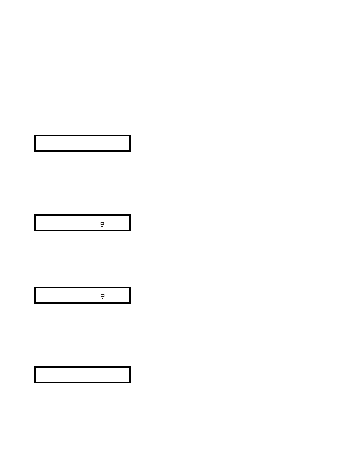
83
TRATAMIENTO DE PROGRAMAS
El DP300 permite almacenar hasta 60 programas diferentes en cada unidad DP300. Mediante el
programa dp:lab (suministrado con el DP300), se podrán almacenar tantas configuraciones como
quepan en el disco duro del sistema. Estos programas se pueden guardar, cargar, modificar, proteger,
etc. Las funciones que tenemos son:
1. Almacenamiento de programas.
2. Carga de programas.
3. Borrado de programas.
1. Almacenamiento de programas
El DP300 dispone de la tecla SAVE/ENTER que permite guardar programas en la memoria de la
unidad. Al pulsar esta tecla, aparecerá una pantalla parecida a esta,
SAVE
10 ECLER
donde 10 es el número de programa y "ECLER" el nombre del mismo. Con las teclas PREVIOUS y
NEXT o la rotación del encoder podremos modificar cada una de las letras de la posición donde se
encuentre el cursor. Para cambiar de dígito (a derecha o izquierda) se deberán utilizar las teclas
? y ?. El nombre puede estar compuesto de hasta 8 dígitos.
Para salir del modo "SAVE", deberemos pulsar la tecla RECALL.
El programa quedará almacenado al pulsar de nuevo la tecla SAVE/ENTER. En ese momento
aparecerá una pantalla preguntando si queremos bloquear el programa.
Store Locked?
Locked
En ella aparecerá la palabra "Locked" y el símbolo de una llave. Si lo queremos guardar bloqueado
pulsaremos de nuevo la tecla SAVE/ENTER, y quedará almacenado. Si no deseamos bloquear el
programa, deberemos girar el encoder o pulsar la tecla ?, y aparecerá la palabra "Unlocked", que nos
indicará que vamos a almacenar el programa sin bloquear.
En caso de querer guardar un programa ya bloqueado, aparecerá durante unos segundos la pantalla,
Program Locked!
10 ECLER
indicándonos que el programa ya está bloqueado. Podremos desbloquearlo con la rotación del encoder
o la tecla ? y almacenarlo de la manera que ya hemos visto.
2. Carga de programas
Mediante la tecla RECALL, podremos cargar los programas almacenados en memoria. El primer
programa que aparecerá será el que se haya utilizado por última vez.
RECALL
10 ECLER
Page 84
84
Se deberá seleccionar el programa que se quiera cargar mediante las teclas PREVIOUS y NEXT o la
rotación del encoder. Si a la derecha del nombre aparece una llave significará que el programa está
bloqueado.
Pulsando de nuevo la tecla RECALL, el programa quedará cargado.
3. Borrado de programas
Para realizar el borrado de programas deberemos acceder a la pantalla Delete Program del menú de
configuración SETUP.
Mediante esta pantalla, podremos borrar alguno de los programas guardados en la unidad. La primera
pantalla en aparecer será:
SETUP
Delete Prog No
Si pulsamos la tecla ? o giramos la rueda del encoder hacia la derecha, entraremos en modo Borrado
de Programa (Delete Program) y aparecerá la pantalla siguiente,
Enter to Delete
6DIGITAL6
donde podremos seleccionar el programa a borrar mediante la rueda del encoder o las teclas ? y ?.
Una vez seleccionado el programa a borrar, pulsaremos la tecla SAVE/ENTER para borrar el programa.
Tener en cuenta que los programas que estén bloqueados deberán ser desbloqueados antes de
realizar el borrado.
9. EJEMPLO DE PROGRAMACIÓN
En este capítulo vamos a explicar el proceso práctico para realizar una programación real de un sistema
estéreo de tres vías (graves-medios-agudos) estándar.
Los parámetros que deberemos cumplir son los siguientes:
-Sistema estéreo de 2 canales 3 vías.
-Filtro pasa banda para graves (Low) de 15Hz a 164Hz
-Filtro pasa banda para medios (Mid) de 164Hz a 1,68kHz
-Filtro pasa altos para agudos (Hi) de 1,68kHz.
-Todos los filtros deberán ser Linkwitz-Riley con pendiente de 24dB/oct.
-El filtro de agudos deberá tener una ecualización a 14,9kHz y ganancia (gain) de +5dB.
-Entradas y salidas sin retardo (delay=0,000ms)
Arrancaremos la unidad y esperaremos a que el display deje de parpadear. Una vez estabilizado,
iniciaremos la configuración del sistema.
Lo primero que deberemos hacer será especificar el modo de funcionamiento. Pulsaremos la tecla
PREVIOUS y accederemos a la pantalla de configuración del modo de funcionamiento para elegir el
modo 2 canales 3 vías (2 ch 3 way).
SETUP
CONFIG MONO
Si giramos el ENCODER hacia la derecha o pulsamos de la tecla ? irán apareciendo de forma
sucesiva las pantallas que nos permitirán cambiar la configuración de MONO a 2 o 3 VÍAS. De origen,
el aparato se suministra en modo MONO.
Page 85
85
Elegiremos el modo 3 way y pulsaremos la tecla ENTER para confirmar la selección.
Change to 3 way?
Enter to confirm
y aparecerá la pantalla ajustada a 2 canales 3 vías.
SETUP
CONFIG 2ch 3 way
En el caso de nuestro ejemplo podemos establecer, si queremos, un enlace estéreo (Stereo link) entre
canales, aunque no es imprescindible. Si no establecemos el enlace deberemos ajustar todos los
parámetros para cada uno de los canales de entrada y salida, mientras que si realizamos el enlace
podremos realizar los ajuste de dos en dos. En este caso recomendamos establecer el enlace estéreo
(Stereo link = On). Pulsaremos la tecla NEXT y aparecerá la siguiente pantalla.
SETUP
Stereo Link ON
Una vez ajustado el modo de funcionamiento, pasaremos a configurar las entradas. Mediante la
pulsación del encoder, accederemos a las entradas IN A & IN B. Mediante las teclas PREVIOUS y
NEXT pasaremos de una pantalla a otra de la configuración de las entradas.
La primera pantalla que encontraremos será del ajuste del retardo (delay). La dejaremos a 0,000ms (sin
retardo).
IN A & IN B
Delay 0.000ms
Inmediatamente después ya aparecerá la pantalla para establecer las ecualizaciones. Debido a que no
queremos aplicar ninguna ecualización a las entradas, abandonaremos el modo de Entradas y
pasaremos a configurar las salidas.
Pulsando de nuevo dos veces el encoder accederemos a la pantalla de configuración de las salidas
enlazadas OUT 1&2. Estas dos salidas serán utilizadas para las vías de graves (Low) del sistema.
La siguiente pantalla es la que aparecerá por defecto.
OUT 1&2 Band 1
Name Band 1
Como se tratarán de dos vías de graves, recomendamos cambiar el nombre, y pasaremos a
denominarlos Low (graves). Mediante el giro del encoder o las teclas ? y ? seleccionaremos el
nombre.
OUT 1&2 Low
Name Low
Page 86
86
Pulsaremos la tecla PREVIOUS y aparecerá la pantalla de fuente de sonido (source). Dejaremos la
selección por defecto, OUT 1-IN A y OUT 2-IN B.
OUT 1&2 Low
Srce IN a & IN B
Pulsaremos la tecla PREVIOUS y aparecerá la pantalla de ganancia (gain). Dejaremos el nivel a 0,0dB
de ganancia.
Al pulsar de nuevo PREVIOUS visualizaremos la pantalla del limitador (limit). El valor por defecto es de
+4dBV. Nosotros ajustaremos el valor a +0,4dBV para dar un pequeño énfasis a la señal sin provocar
un exceso de nivel a la salida.
Si queremos aplicar algún limitador deberemos ajustar el valor deseado. No es el caso de nuestro
ejemplo.
Igual que las dos pantallas anteriores, al pulsar PREVIOUS aparecerá la de retardo (delay) y después
la del enlace de retardo (delay link), que también dejaremos tal y como están por defecto,
delay = 0,000ms y delay link = Off.
Pulsando de nuevo aparecerá la pantalla de polaridad (polarity), que dejaremos en "normal".
A partir de este momento empezarán a aparecer las pantallas que determinarán la forma y
características del filtro.
En este caso deseamos ajustar un filtro tipo Linkwitz-Riley con pendientes de subida y bajada de
24dB/octava y frecuencia de corte inferior de 15Hz y superior de 164Hz.
Pulsaremos la tecla PREVIOUS y aparecerá la pantalla para ajustar la pendiente inferior del filtro (Lo
Shape). Mediante el giro de la rueda del encoder o las teclas ? y ? elegiremos de la lista la opción
"L-R 24" es decir, Linkwitz-Riley de 24dB/octava.
OUT 1&2 Low
Lo Shape L-R 24
Pulsaremos de nuevo PREVIOUS y aparecerá la pantalla para seleccionar la frecuencia de corte
inferior (Hi pass). Mediante el giro de la rueda del encoder o las teclas ? y ? ajustaremos el valor a
15Hz.
OUT 1&2 Low
Hi pass 15.0Hz
Al pulsar PREVIOUS de nuevo aparecerá la pantalla para ajustar la pendiente superior del filtro
(Hi shape). Mediante el giro de la rueda del encoder o las teclas ? y ? elegiremos de la lista la opción
"L-R 24" es decir, Linkwitz-Riley de 24dB/octava.
OUT 1&2 Low
Hi Shape L-R 24
Page 87
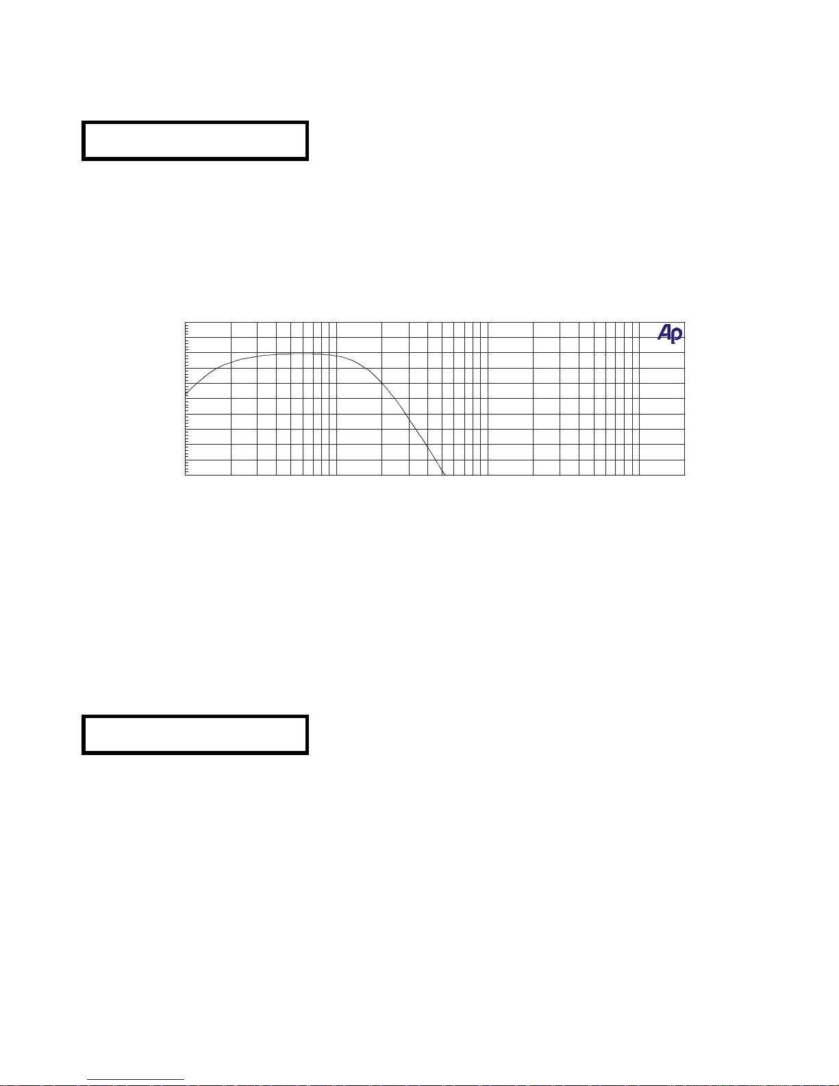
87
Pulsaremos de nuevo PREVIOUS y aparecerá la pantalla para seleccionar la frecuencia de corte
superior (Lo pass). Mediante el giro de la rueda del encoder o las teclas ? y ? ajustaremos el valor a
164Hz.
OUT 1&2 Low
Hi pass 164Hz
Si pulsamos PREVIOUS aparecerá la pantalla para ajustar las ecualizaciones. Dado que no deseamos
asignar ninguna ecualización, abandonaremos la configuración de las salidas 1 y 2 pulsando el
encoder. Esto permitirá acceder a las entradas 3 y 4.
Los ajustes realizados a los parámetros de las salidas 1 y 2 dará como resultado una curva de
respuesta de graves como la siguiente:
Procederemos ahora a efectuar el ajuste de los parámetros de los salidas 3 y 4 que hemos asignado en
nuestro ejemplo como vías de medios (Mid). El mecanismo de funcionamiento de la configuración de
los parámetros es idéntico al explicado para los parámetros de las salidas 1 y 2 de graves (Low). Por
esta razón, explicaremos de forma más resumida el ajuste de los parámetros comunes a las salidas
1 y 2.
En este caso deseamos ajustar un filtro tipo Linkwitz-Riley con pendientes de subida y bajada de
24dB/octava y frecuencia de corte inferior de 164Hz y superior de 1,68kHz.
Lo primero que deberemos hacer es pulsar la tecla NEXT las veces que sea necesario para acceder a
la pantalla de ajuste del nombre. Una vez allí y dado que se trata de vías de medios (Mid) asignaremos
este nombre a las salidas 3 y 4.
OUT 3&4 Mid
Name Mid
Pulsaremos la tecla PREVIOUS ajustando los parámetros de fuente de audio (source), ganancia (gain),
limitador (limit), retardo (delay), enlace de retardo (delay link) y polaridad (polarity) de la misma manera
que hemos ajustado las salidas 1 y 2.
ECLER S.A.
01/31/05 15:35:31
-40
+10
-35
-30
-25
-20
-15
-10
-5
+0
+5
d
B
r
A
10
20k2050
100
200
5001k2k5k10k
Page 88
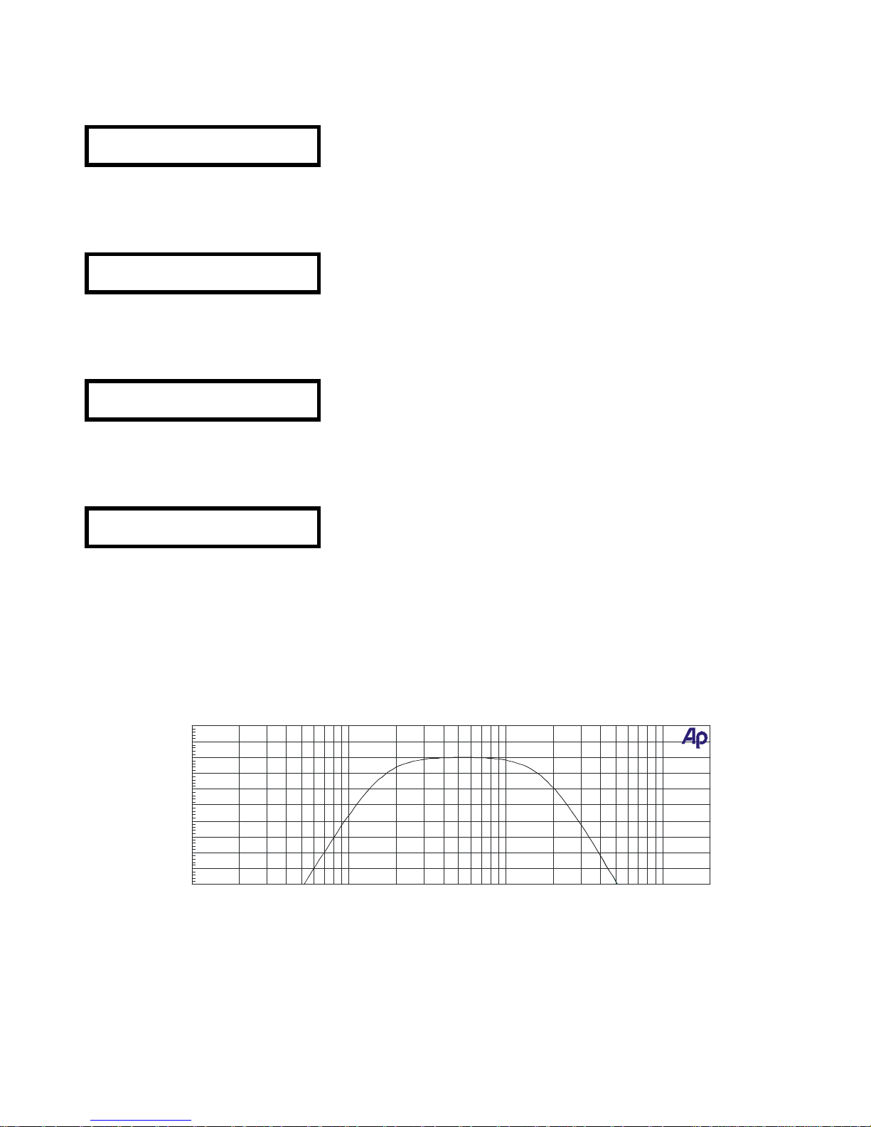
88
Pulsaremos la tecla PREVIOUS y aparecerá la pantalla para ajustar la pendiente inferior del filtro
(Lo Shape). Mediante el giro de la rueda del encoder o las teclas ? y ? elegiremos de la lista la opción
"L-R 24" es decir, Linkwitz-Riley de 24dB/octava.
OUT 3&4 Mid
Lo Shape L-R 24
Pulsaremos de nuevo PREVIOUS y aparecerá la pantalla para seleccionar la frecuencia de corte
inferior (Hi pass). Mediante el giro de la rueda del encoder o las teclas ? y ? ajustaremos el valor a
164Hz.
OUT 3&4 Mid
Hi pass 164Hz
Al pulsar PREVIOUS de nuevo aparecerá la pantalla para ajustar la pendiente superior del filtro
(Hi shape). Mediante el giro de la rueda del encoder o las teclas ? y ? elegiremos de la lista la opción
"L-R 24" es decir, Linkwitz-Riley de 24dB/octava.
OUT 3&4 Mid
Hi Shape L-R 24
Pulsaremos de nuevo PREVIOUS y aparecerá la pantalla para seleccionar la frecuencia de corte
superior (Lo pass). Mediante el giro de la rueda del encoder o las teclas ? y ? ajustaremos el valor a
1,68kHz.
OUT 3&4 Mid
Hi pass 1.68kHz
Si pulsamos PREVIOUS aparecerá la pantalla para ajustar las ecualizaciones. Dado que no deseamos
asignar ninguna ecualización, abandonaremos la configuración de las salidas 3 y 4 pulsando el
encoder. Esto permitirá acceder a las salidas 5 y 6.
Los ajustes realizados a los parámetros de las salidas 3 y 4 dará como resultado una curva de
respuesta de medios como la siguiente:
Procederemos ahora a efectuar el ajuste de los parámetros de las salidas 5 y 6 que hemos asignado en
nuestro ejemplo como vías de agudos (High). El mecanismo de funcionamiento de la configuración de
los parámetros es idéntico al explicado para los parámetros de las salidas 1/2 y 3/4.
ECLER S.A.
01/31/05 15:38:35
-40
+10
-35
-30
-25
-20
-15
-10
-5
+0
+5
d
B
r
A
10 20k20 50 100 200 500 1k 2k 5k 10k
Hz
Page 89
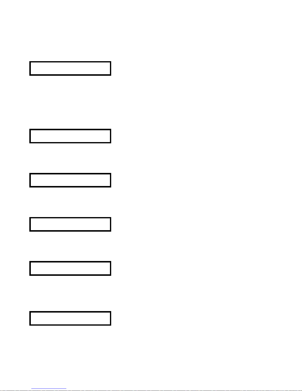
89
En este caso deseamos ajustar un filtro pasa altos tipo Linkwitz-Riley con pendiente de 24dB/octava y
frecuencia de corte inferior de 1,68kHz.
Lo primero que deberemos hacer es pulsar la tecla NEXT las veces que sea necesario para acceder a
la pantalla de ajuste del nombre. Una vez allí y dado que se trata de vías de agudos (High)
asignaremos este nombre a las salidas 5 y 6.
OUT 5&6 High
Name High
Pulsaremos la tecla PREVIOUS ajustando los parámetros de fuente de audio (source), ganancia (gain),
limitador (limit), retardo (delay), enlace de retardo (delay link) y polaridad (polarity) de la misma manera
que hemos ajustado las salidas 1&2 y 3&4.
Pulsaremos la tecla PREVIOUS y aparecerá la pantalla para ajustar la pendiente inferior del filtro
(Lo Shape). Mediante el giro de la rueda del encoder o las teclas ? y ? elegiremos de la lista la opción
"L-R 24" es decir, Linkwitz-Riley de 24dB/octava.
OUT 5&6 High
Lo Shape L-R 24
Pulsaremos de nuevo PREVIOUS y aparecerá la pantalla para seleccionar la frecuencia de corte
inferior (Hi pass). Mediante el giro de la rueda del encoder o las teclas ? y ? ajustaremos el valor a
1,68kHz.
OUT 5&6 High
Hi pass 1.68kHz
Al pulsar PREVIOUS de nuevo aparecerá la pantalla para ajustar la pendiente superior del filtro
(Hi shape). Mediante el giro de la rueda del encoder o las teclas ? y ? elegiremos de la lista la opción
"L-R 24" es decir, Linkwitz-Riley de 24dB/octava.
OUT 5&6 High
Hi Shape L-R 24
Pulsaremos de nuevo PREVIOUS y aparecerá la pantalla para seleccionar la frecuencia de corte
superior (Lo pass). Mediante el giro de la rueda del encoder o las teclas ? y ? ajustaremos el valor a
OUT. Esto significa que se trata de un filtro pasa altos sin pendiente superior.
OUT 5&6 High
Hi pass OUT
Si pulsamos PREVIOUS aparecerá la pantalla para ajustar las ecualizaciones. En este caso deseamos
ajustar un énfasis de +5dB a una frecuencia de 14,9kHz.
La primera pantalla que aparecerá será la del tipo de curva del filtro. Seleccionaremos la de tipo "bell"
(campana).
OUT 5&6 High
Eq1S Bell Sp14
Page 90
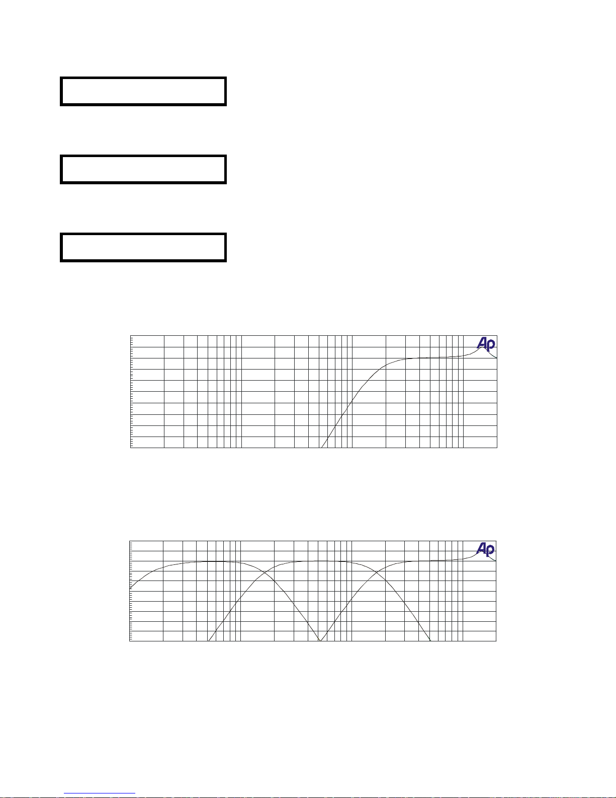
90
Pulsaremos la tecla PREVIOUS y aparecerá la pantalla para ajustar la frecuencia a la que se aplicará la
ecualización.
OUT 5&6 High
Eq1S Fq 14.9kHz
Pulsando de nuevo PREVIOUS aparecerá la pantalla para ajustar el nivel de ganancia. Ajustaremos
+5dB.
OUT 5&6 High
Eq1S +- +5dB
La próxima pantalla en aparecer será la del ancho (Wd) en el DP300 de la curva de ecualización. En
este caso la dejaremos a su valor por defecto a 0,3 octavas.
OUT 5&6 High
Eq1S Wd 0.3Oct
Los ajustes realizados a los parámetros de las salidas 5 y 6 dará como resultado una curva de
respuesta de agudos como la siguiente:
Una vez ajustados los parámetros de los tres filtros, la curva de respuesta resultante del DP300
quedará de la manera siguiente:
Con este procedimiento hemos configurado un sistema estéreo de tres vías con filtro para graves,
medios y agudos.
ECLER S.A.
01/31/05 15:40:14
-40
+10
-35
-30
-25
-20
-15
-10
-5
+0
+5
d
B
r
A
10 20k20 50 100 200 500 1k 2k 5k 10k
Hz
ECLER S.A.
01/31/05 15:41:52
-40
+10
-35
-30
-25
-20
-15
-10
-5
+0
+5
d
B
r
A
10 20k20 50 100 200 500 1k 2k 5k 10k
Hz
Page 91
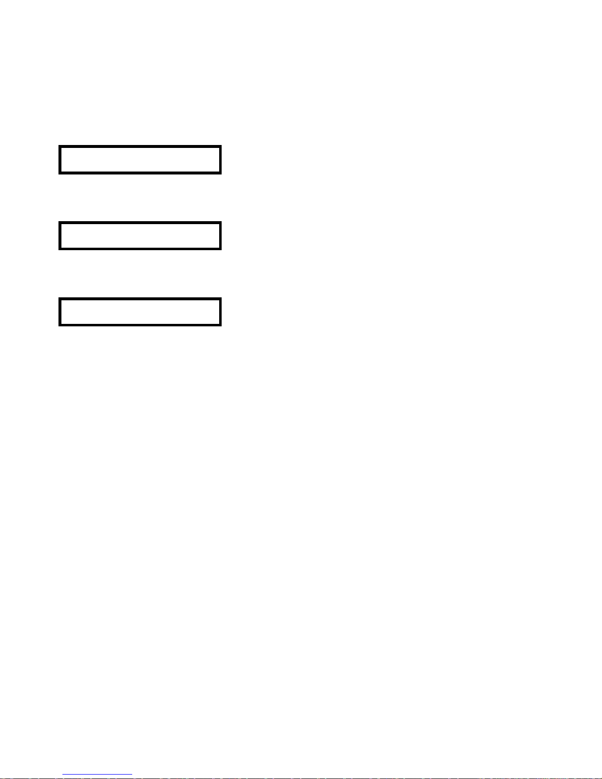
91
Una vez realizada la configuración de todos los parámetros de funcionamiento, deberemos
almacenarlos en la memoria del DP300. Para ello pulsaremos la tecla SAVE y entraremos en el modo
de guardado (save) del programa en el DP300.
Aparecerá una pantalla para introducir el nombre y la posición que ocupará dentro de la memoria.
Mediante las teclas ? y ? accederemos a cada una de las posiciones del nombre (incluido el carácter
de número de programa) y mediante la rotación del encoder y las teclas PREVIOUS y NEXT
modificaremos el carácter de cada una de las posiciones.
SAVE
1 ECLER
Podremos introducir un nombre de hasta 8 caracteres. Pulsando de nuevo la tecla SAVE aparecerá una
pantalla que nos preguntará si queremos guardar el programa con un bloqueo.
Store Locked?
Locked
Mediante la rotación del encoder o las teclas ? y ? modificaremos la selección de "Locked"
(bloqueado) a "Unlocked" (desbloqueado).
Store Locked?
Unlocked
Pulsaremos de nuevo la tecla SAVE y el programa quedará almacenado en la memoria del DP300.
Page 92
92
10. SOFTWARE
Software dp:lab
El DP300 dispone de un software asociado, el dp:lab, que permite realizar la
configuración de todos los parámetros del aparato desde un ordenador PC o
portátil que cumpla con los siguientes requisitos mínimos del sistema:
-Procesador Intel P3 a 600MHz o equivalente.
-128 Mbytes de memoria RAM.
-Sistema operativo Windows 98 SE, Me, XP Home, XP Professional o Windows 2000.
Mediante esta aplicación de software, se podrán configurar el modo de funcionamiento y los filtros del
crossover y las ecualizaciones de las entradas y salidas de la misma forma que se haría desde la propia
unidad.
La comunicación entre el ordenador y el DP300 se realizará mediante un cable serie RS-232
(suministrado con el DP300).
¡Atención:¡ Es importante remarcar que para que el DP300 se ponga en comunicación con el dp:lab, la
configuración "Midi mode" del DP300 deberá estar como "PCPort" y el canal de Midi deberá ser el
número 1.
Una vez realizada la programación, se puede descargar este programa directamente al DP300 vía
comunicación serie RS-232.
Instalación del dp:lab
Antes de nada, se deberá instalar el programa en el ordenador que utilizaremos como plataforma de
comunicación. Para ello, dispondremos del fichero de aplicación. En este caso se trata del fichero de
instalación de la versión 1.32 (V132), pero está sujeta a variaciones debido a modificación o mejoras de
software.
Page 93
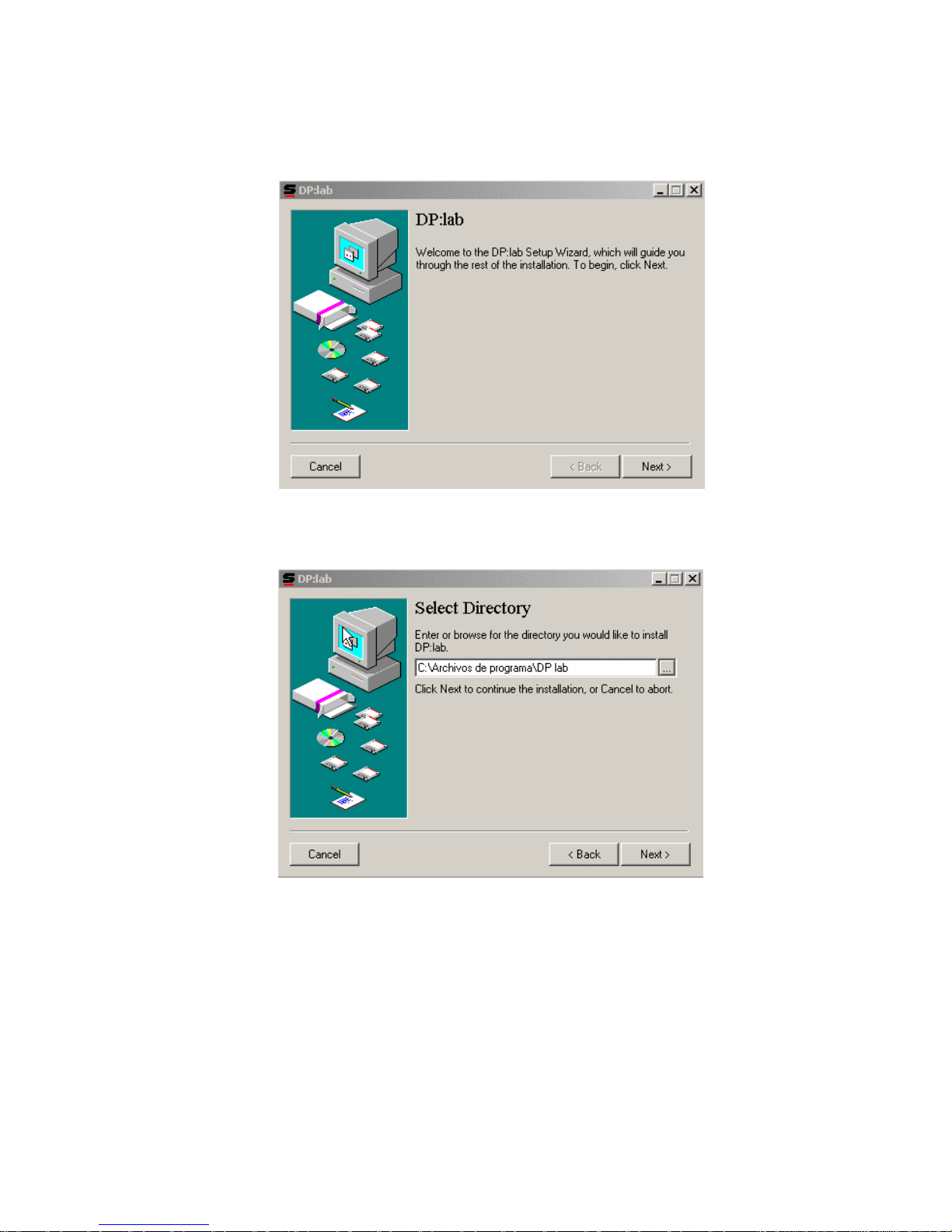
93
Este fichero se deberá ejecutar para iniciar el proceso de instalación del programa.
Haciendo doble click sobre la aplicación, se iniciará la instalación del programa dp:lab, y aparecerá la
pantalla siguiente donde nos informa sobre el proceso de instalación del programa y nos pide que
continuemos con la instalación.
Pulsaremos la tecla Next> y aparecerá la pantalla siguiente, que nos preguntará por el directorio de
instalación del programa.
Page 94
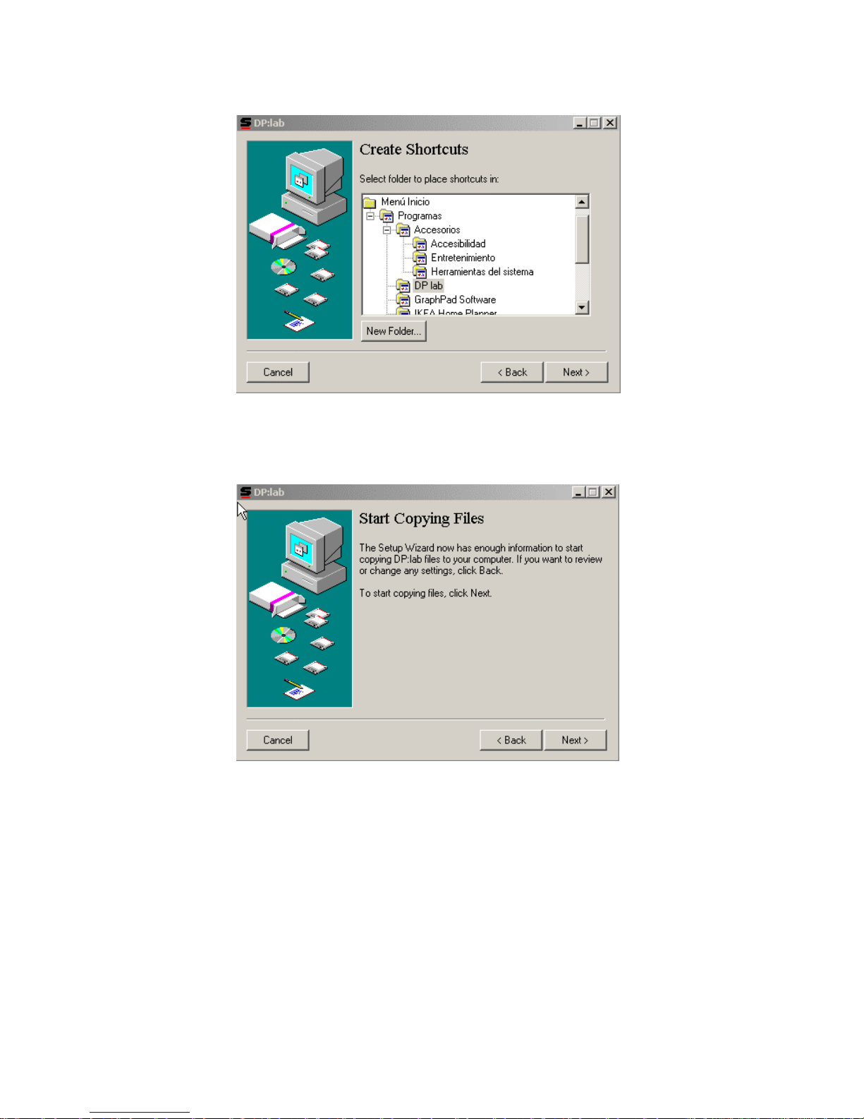
94
Una vez introducida la ruta, (si es que queremos cambiar la de por defecto), pulsaremos de nuevo la
tecla Next>, apareciendo la pantalla siguiente.
Que nos preguntará por la ubicación del icono de acceso directo al programa dp:lab. Normalmente,
elegiremos la asignación por defecto. Pulsaremos de nuevo Next> y aparecerá la siguiente pantalla de
instalación.
Esta pantalla nos informa que inmediatamente, al pulsar Next> se va iniciar el proceso de copia de
archivos. Pulsaremos Next> de nuevo.
Page 95
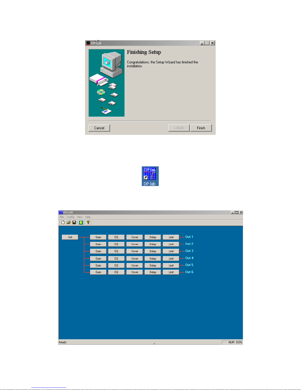
95
Realizará la copia de los ficheros hasta que aparezca la última pantalla de instalación, que nos
informará que la misma se ha realizado con éxito.
Pulsaremos Finish para terminar la instalación.
Una vez realizada la instalación, en el escritorio aparecerá un acceso directo que permitirá la ejecución
del programa dp:lab.
Una vez realizada la instalación, se podrá ejecutar el programa y realizar los ajustes de los parámetros
a configurar. Al ejecutar el programa, aparecerá la ventana principal.
Page 96
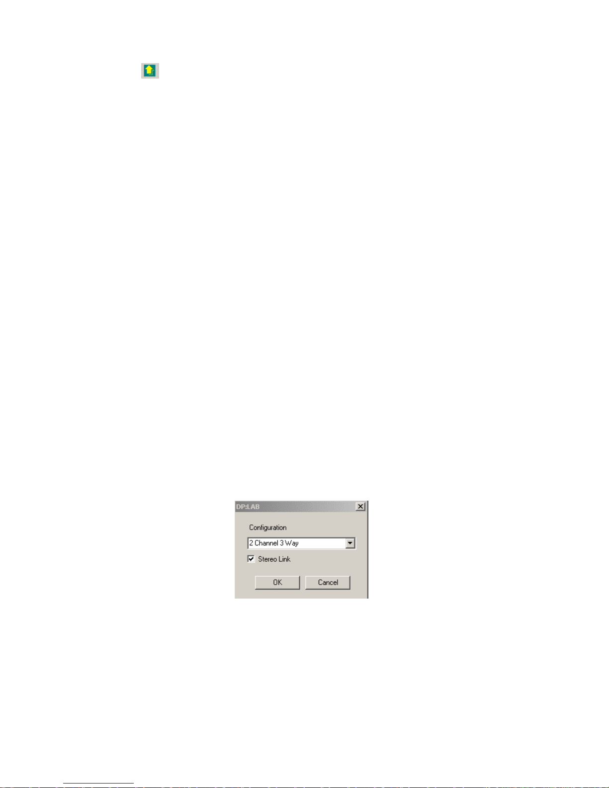
96
En ella se puede acceder de forma directa al modo de configuración entrada/salida y los botones
estándar de acceso directo a "Fichero nuevo", "Abrir", "Guardar" y "Ayuda (?). Además existe un botón
con una flecha que permite comprobar si se ha establecido satisfactoriamente la comunicación
serie entre el dp:lab y el DP300 y cargar automáticamente el programa activo en el DP300 al dp:lab.
Si la comunicación no se puede realizar (fallo de cable, de asignación de puerto COM, de canal Midi)
aparecerá un mensaje de error.
En la ventana principal dispone de acceso a los menús File, Config, View, Help y Exit.
Al desplegar el menú File, disponemos de las opciones siguientes:
-New, para crear un fichero nuevo.
-Open, para abrir un fichero ya existente.
-Save, para guardar el fichero que estamos utilizando.
-Save As, para guardar el fichero actual con un nombre nuevo.
-Exit, para salir del programa dp:lab.
El menú Config dispone de las opciones siguientes:
-Configuration, para configurar el modo de funcionamiento (mono....).
-RS232, para asignar el puerto de comunicación serie.
-Memory, para gestionar los programas almacenados en la memoria del ordenador y del DP300
de forma remota.
En el menú View se puede activar la visualización de la barra de herramientas (Toolbar) y de la barra de
estado (Status bar).
El menú Help nos informa sobre la versión del dp:lab.
Este manual se centrará específicamente en el menú Config, que será el que permita configurar y
controlar de forma remota el DP300.
MENÚ CONFIG
Configuración
Esta opción permitirá configurar el modo de funcionamiento de audio del DP300. Al elegir la opción
Configuration, aparecerá la ventana siguiente,
que nos permitirá elegir el modo de funcionamiento.
Page 97
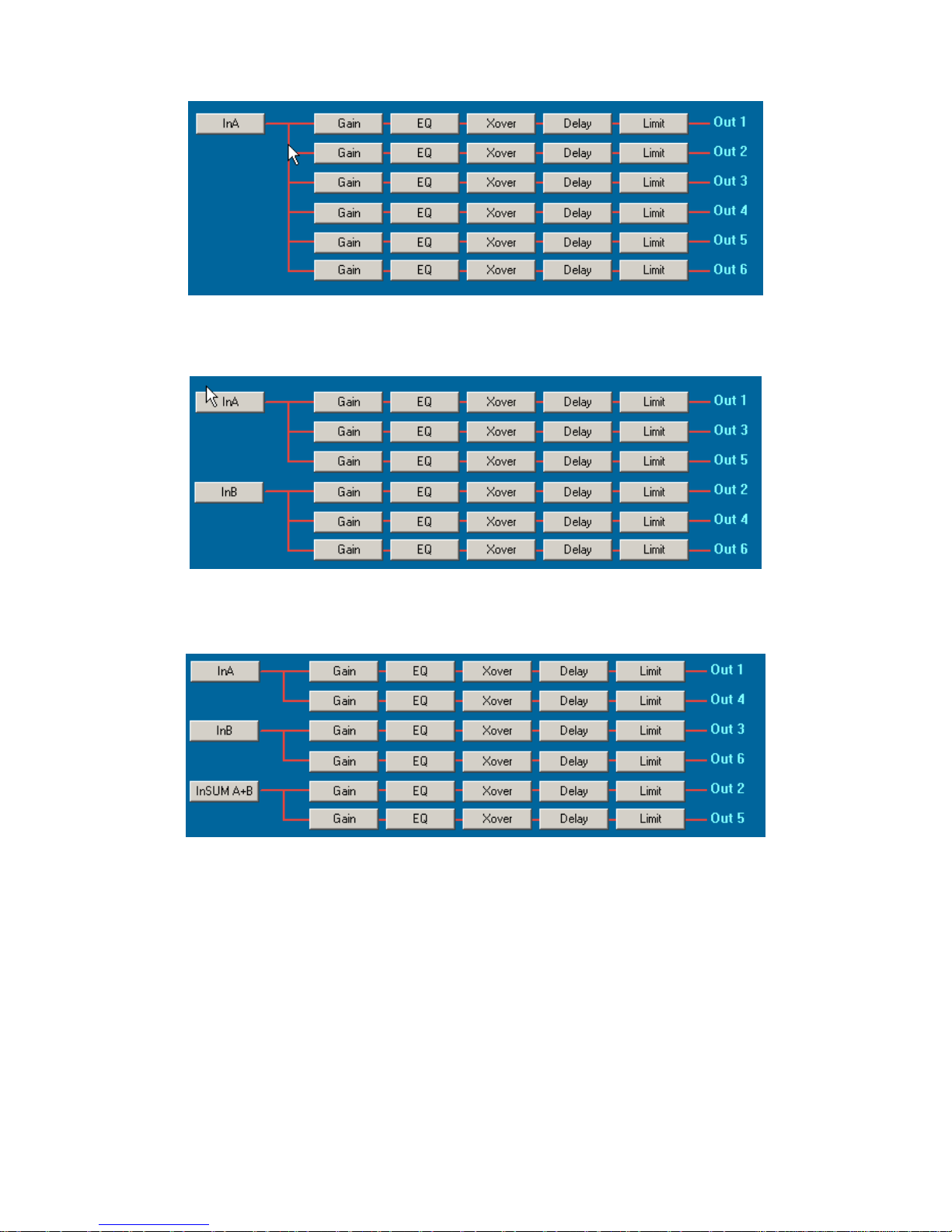
97
Modo Mono
Modo 2 canales 3 vías (2 channel 3 way)
Modo 3 canales 2 vías (3 channel 2 way)
En los modos estéreo, podremos elegir si deseamos disponer de enlace estéreo (stereo link) o no. En
modo Mono, no se activa esta opción.
Page 98
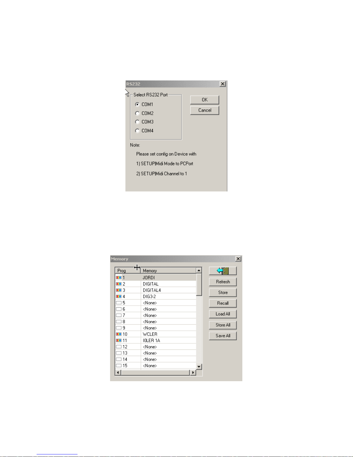
98
RS 232
Esta opción nos permitirá elegir el puerto de comunicación serie (COM1-4) elegido para realizar la
comunicación con el DP300. Esta comunicación se realizará mediante la instalación de un cable serie
D-SUB9 macho-hembra (suministrado con el DP300) entre los conectores de puerto serie del
ordenador y el DP300. Además nos informa de la configuración que deberá tener el DP300 para que la
comunicación se realice con éxito.
Deberemos configurar el DP300 en Modo Midi PCPort y en el canal Midi número 1.
Memory
Mediante esta opción se podrán gestionar de forma remota, desde el programa del PC, los programas
almacenados en la memoria del DP300.
Page 99
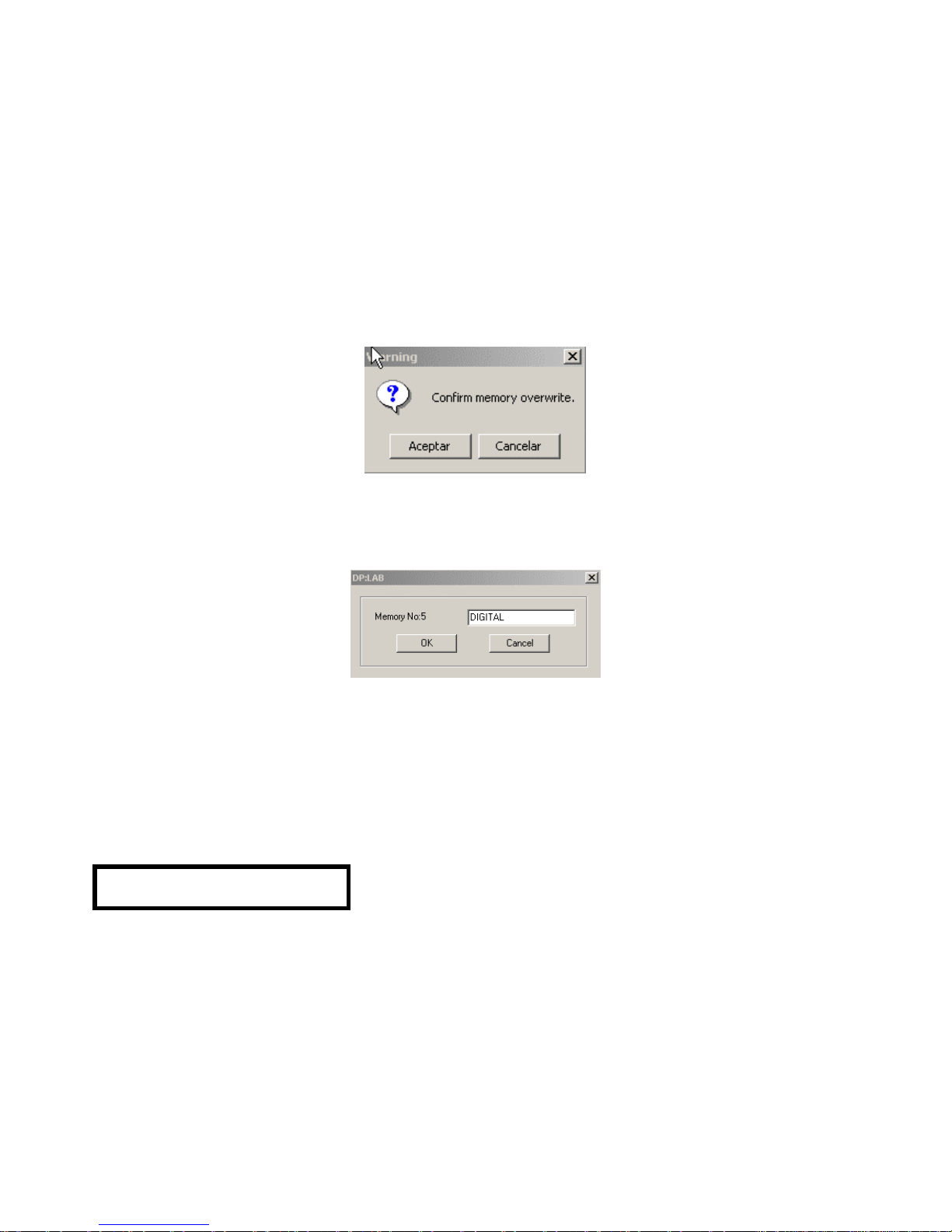
99
Disponemos de las opciones siguientes:
Refresh (Refresco)
Permite actualizar y visualizar en la ventana del PC todos los programas que están almacenados
actualmente en el DP300. En esta ventana aparecerán los programas del DP300 en el orden, posición y
nombre con el que estén almacenados.
Store (Almacenar)
Permite almacenar en la memoria del DP300 marcada como activa en la ventana “Memory” la
configuración que se tenga actualmente en funcionamiento en el dp:lab.
Deberemos tener en cuenta que al ejecutar esta acción, el programa pedirá confirmación para
sobrescribir la posición de programa del DP300.
Una vez confirmada la sobreescritura, nos preguntará por el nombre que queremos asignar al programa
realizado. Este programa se almacenará sobre la posición que tengamos activada en la pantalla
“Memory”.
En caso de aceptar, se almacenará en la posición seleccionada del DP300 los ajustes y parámetros
actualmente activos en el dp:lab.
Recall
Esta opción permite efectuar de forma remota la misma función de RECALL ya explicada en el DP300.
Al pulsar la opción RECALL del dp:lab (por ejemplo para cargar el programa DIGITAL de la posición 2),
en el DP300 se mostrará la pantalla,
RECALLING 00
2 DIGITAL
y se cargará el programa DIGITAL en la posición 2 del DP300.
Load All
Esta función permite cargar los ficheros de memoria almacenados en el disco del PC.
Estos ficheros tienen formato “nombre.ay”, y almacenan la estructura y los programas tal y como están
organizados en el DP300.
Page 100

100
Store All
Almacena en la memoria del DP300 todos los programas a la vez. Cada programa se almacenará en su
posición y con la configuración y ajustes que tengan en este momento.
En el DP300 aparecerá un mensaje informativo alertando de la entrada de una comunicación externa
proveniente del dp:lab.
WARNING!
Incoming Dump
Save All
Esta función permite guardar los ficheros de memoria al disco del PC.
Estos ficheros tienen formato “nombre.ay”, y almacenan la estructura y los programas tal y como están
organizados en el DP300.
 Loading...